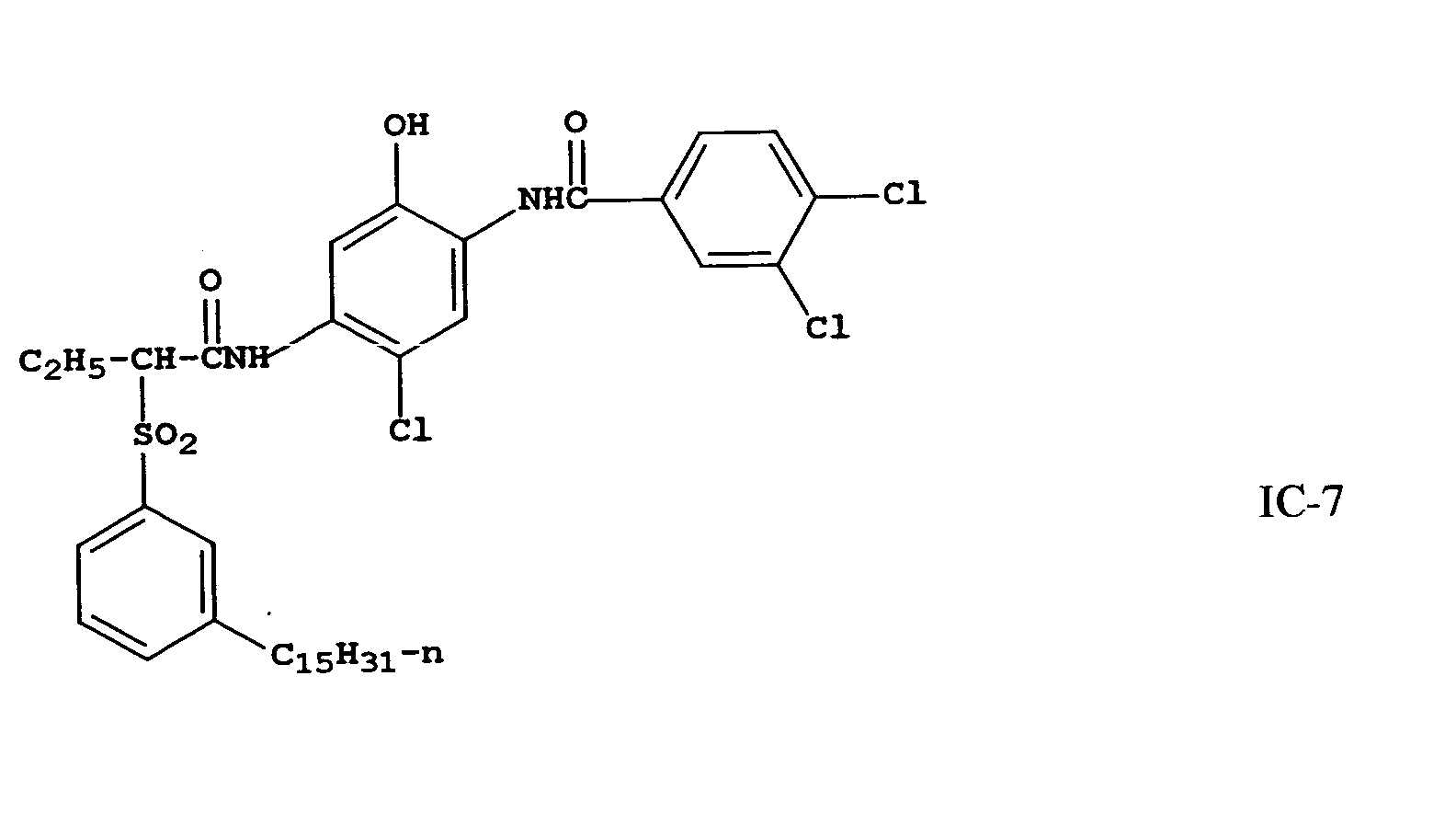
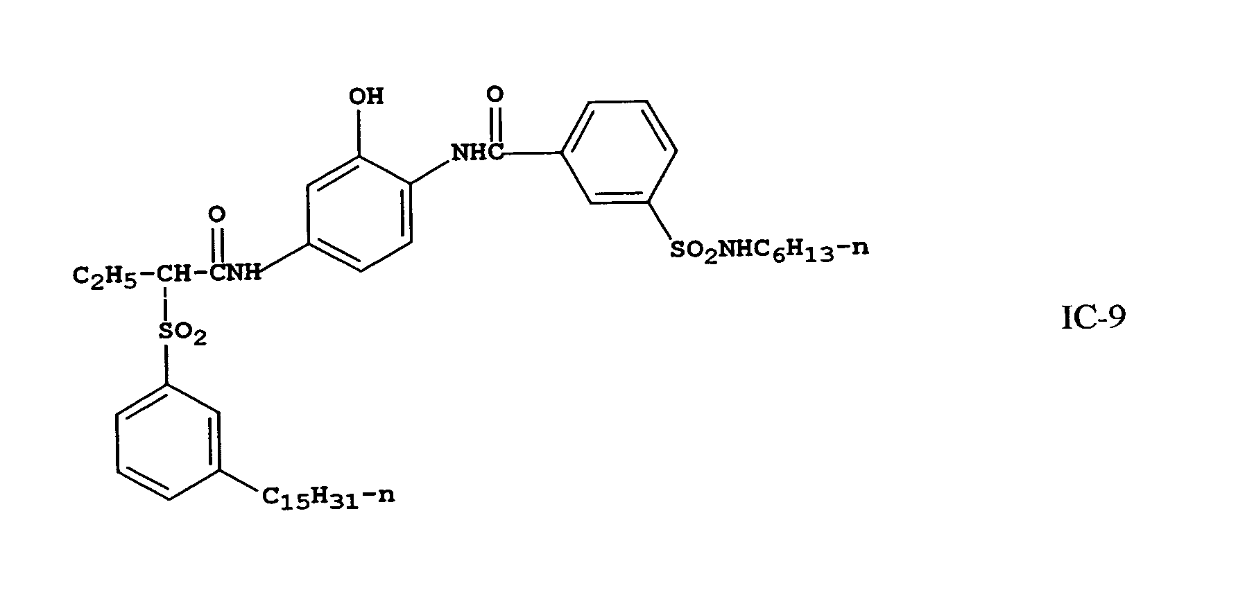
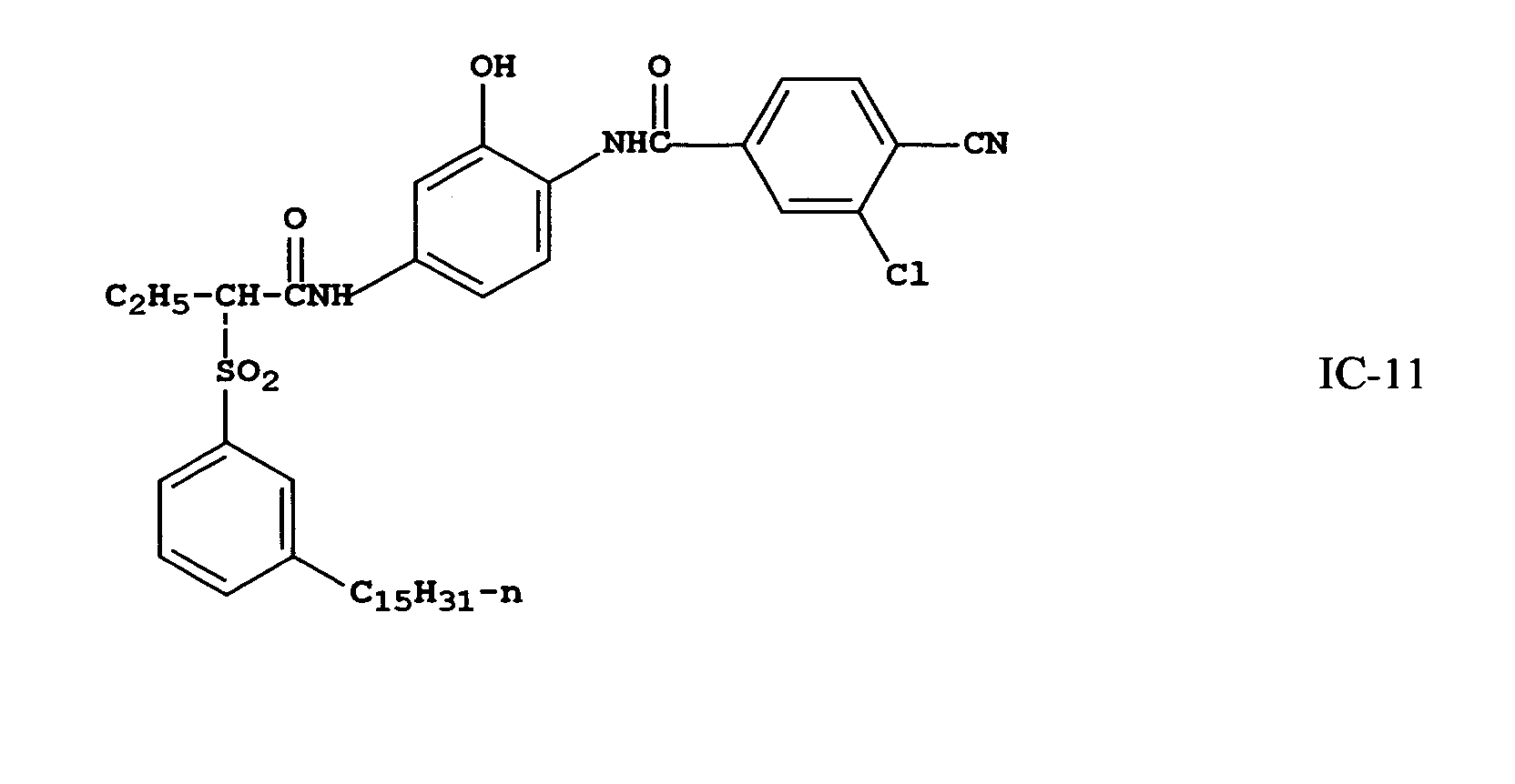
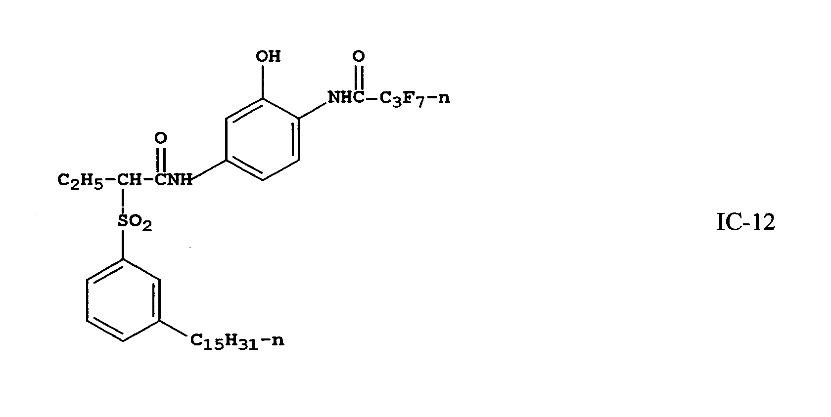
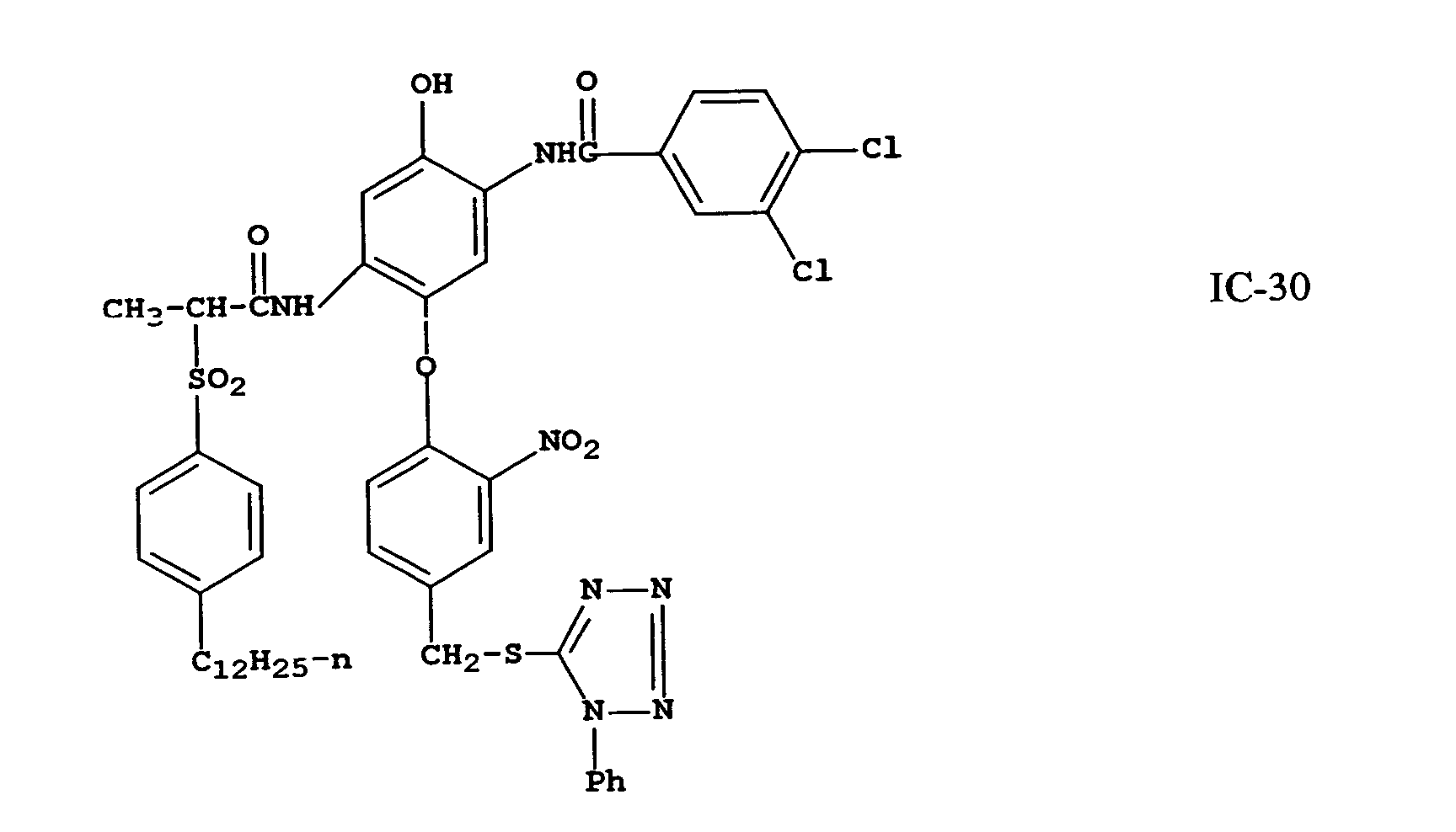
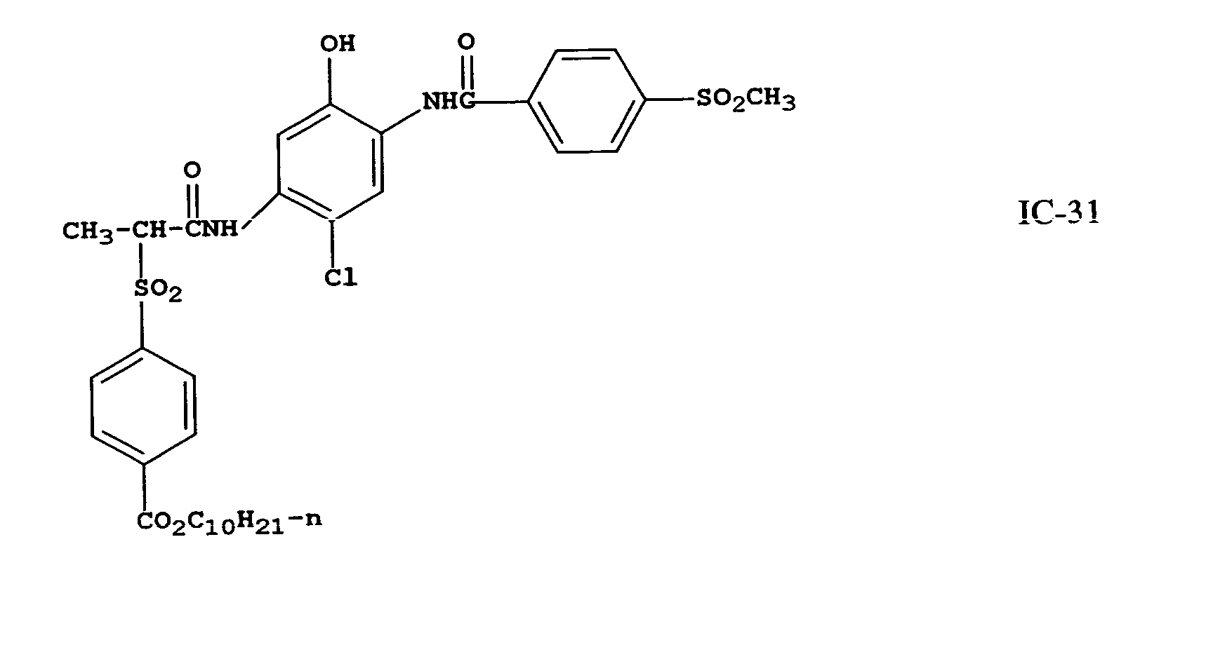
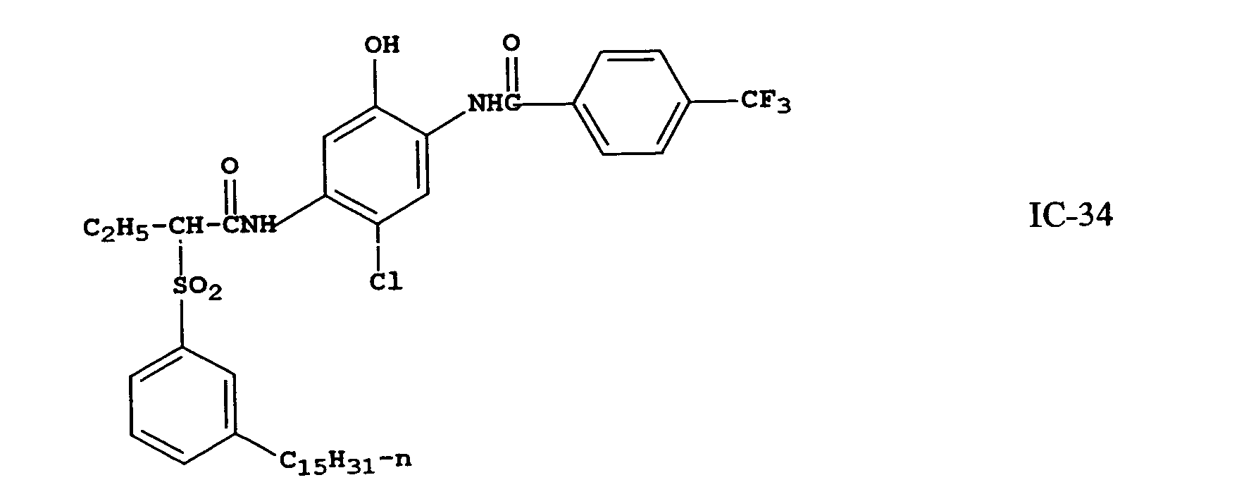
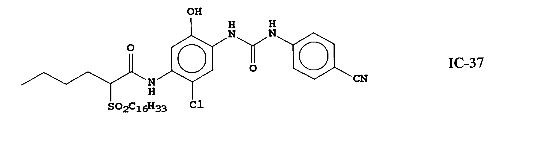
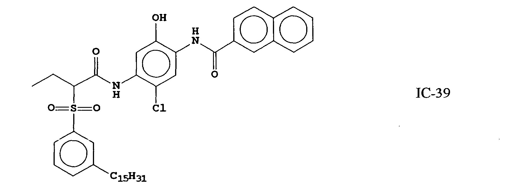
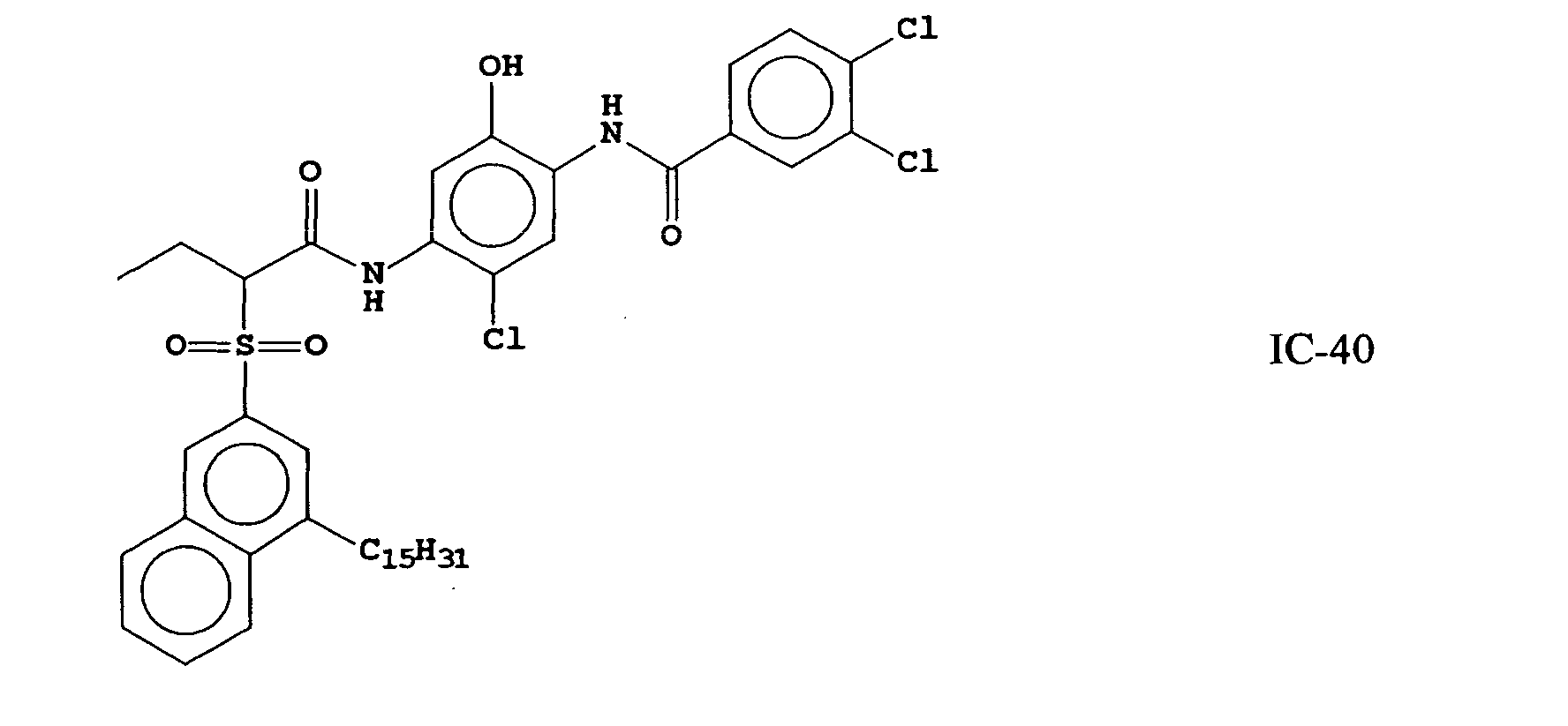
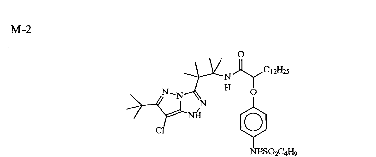
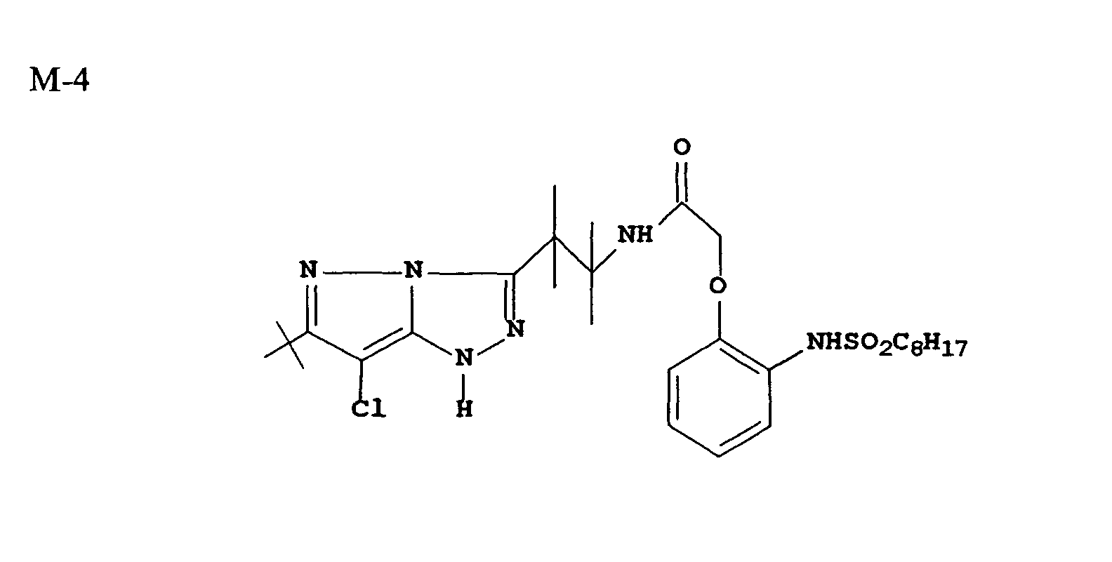
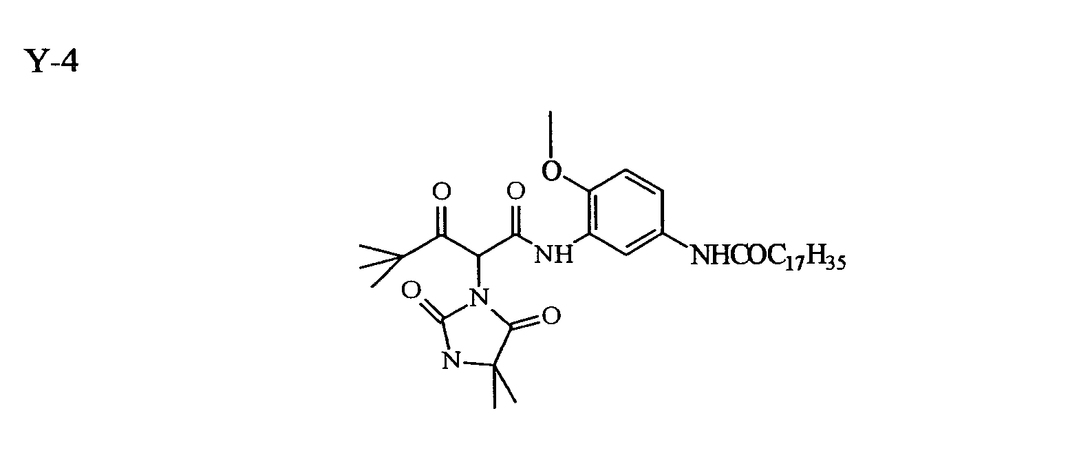
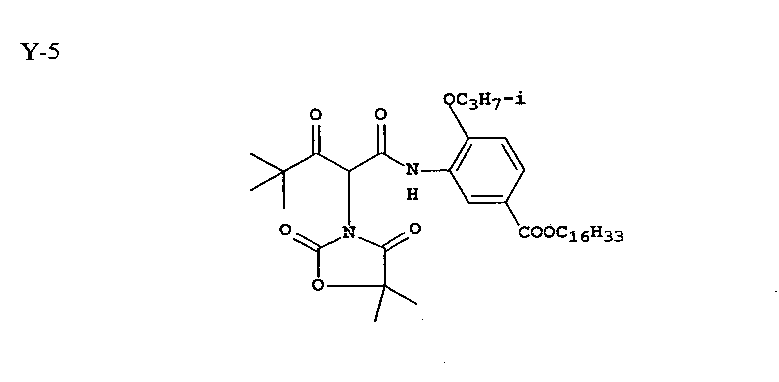
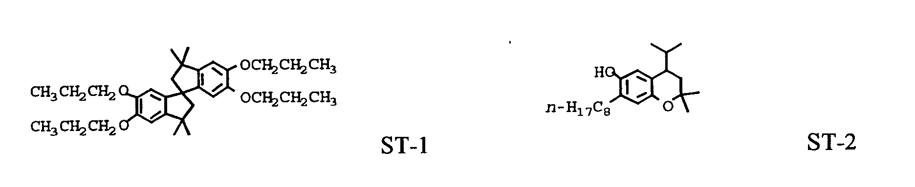
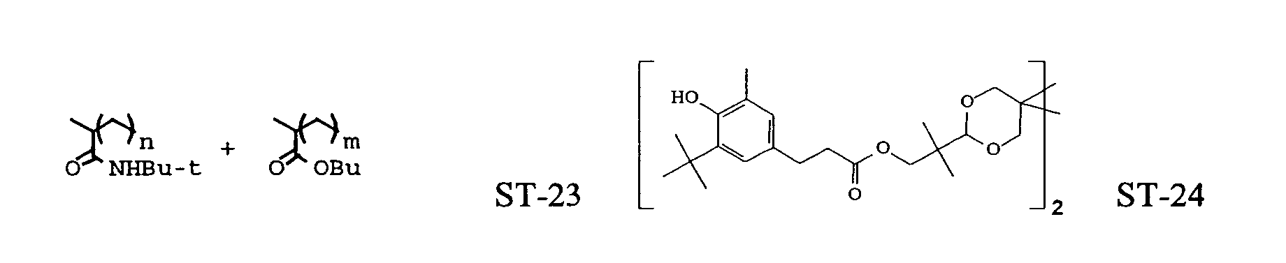
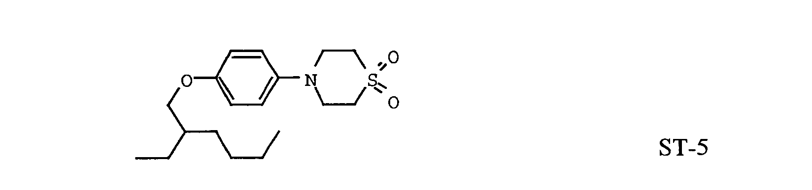
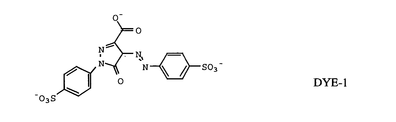
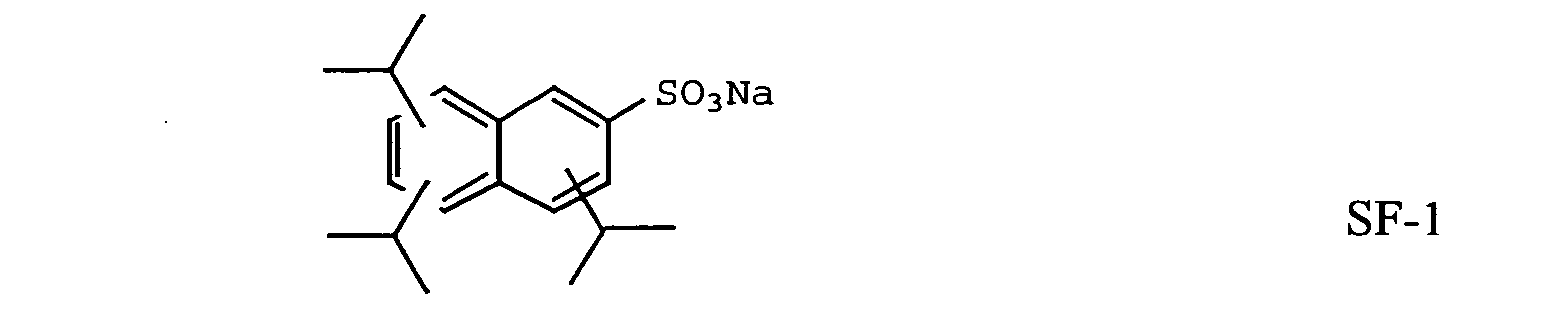
The present invention relates to a novel translucent nonvoided
nanocomposite support for use in photographic reflection and transmission
imaging applications.
It is known in the art that photographic display materials are
utilized for advertising, as well as decorative displays of photographic images.
Since these display materials are used in advertising, the image quality of the
display material is desirable in expressing the quality message of the product or
service being advertised. Further, a photographic display image needs to be high
impact, as it attempts to draw consumer attention to the display material and the
desired message being conveyed. Typical applications for display material
include product and service advertising in public places such as airports, buses
and sports stadiums, movie posters, and fine art photography. The desired
attributes of a quality, high impact photographic display material are a slight blue
density minimum, durability, sharpness, and flatness. Cost is also important, as
display materials tend to be expensive compared with alternative display material
technology such as lithographic images on paper. For display materials,
traditional color paper is undesirable, as it suffers from a lack of durability for the
handling, photo processing, and display of large format images.
Prior art photographic display materials historically have been
classified as either reflection or transmission. Reflection display material
typically is highly pigmented image supports with a light sensitive silver halide
coating applied. Reflection display materials are typically used in commercial
applications where an image is used to convey an idea or message. An
application example of a reflection display material is product advertisement in a
public area. Prior art reflection display materials have been optimized to provide
a pleasing image using reflective light. Transmission display materials are used in
commercial imaging applications and are typically backlit with a light source.
Transmission display materials are typically a clear support with a light sensitive
silver halide and an incorporated diffuser (to hide the "show through" of the
lamps used to provide viewing illumination) or a substantially transparent support
coated with a light sensitive silver halide emulsion which requires a diffusing
screen to be placed behind the material as a means to obscure the "show through"
of the lamps used to provide illumination to the media. Prior art transmission
display materials have been optimized to provide a pleasing image when the
image is backlit with a variety of light sources. Because prior art reflection and
transmission products have been optimized to be either a reflection display image
or a transmission display image, two separate product designs must exist in
manufacturing, and two inventories of display materials must be maintained at the
photofinishing printing site. Further, the quality of the backlighting for
transmission display material is diminished when, for example, a backlight bums
out or the output of the backlight decreases with the age, the transmission image
will appear dark and reduce the commercial value of the image. It would be
desirable if an image support could function both as a reflection and transmission
display material.
Prior art transmission display materials use a high coverage of light
sensitive silver halide emulsion to increase the density of the image compared to
photographic reflection print materials. While increasing the coverage does
increase the density of the image in transmission space, the time to image
development is also increased as the coverage increases. Typically, a high-density
transmission display material has a developer time of at least 110 seconds
compared to a developer time of 45 seconds or less for photographic print
materials. Prior art high-density transmission display materials, when processed,
reduce the productivity of the development lab. Further, coating a high coverage
of emulsion requires additional drying of the emulsion in manufacturing, which
reduces the productivity of emulsion coating machines. It would be desirable if a
transmission display material was high in density and had a developer time less
than 50 seconds.
Prior art reflection photographic materials with a polyester base
use a TiO2 pigmented polyester base onto which light sensitive silver halide
emulsions are coated. It has been proposed in WO 94/04961 to use opaque
polyester containing 10% to 25% TiO2 for a photographic support. The TiO2 in
the polyester gives the reflection display materials an undesirable opalescent
appearance. The TiO2 pigmented polyester also is expensive because the TiO2
must be dispersed into the entire thickness, typically from 100 to 180 µm. The
TiO2 used in this fashion gives the polyester support a slight yellow tint, which is
undesirable for a photographic display material. For use as a photographic
display material, the polyester support containing TiO2 must be tinted blue to
offset the yellow tint of the polyester, causing a loss in desirable whiteness and
adding cost to the display material.
Prior art photographic display material uses polyester as a base for
the support. Typically the polyester support is from 150 to 250 µm thick to
provide the required stiffness. Prior art photographic display materials are
typically coated with light sensitive silver halide imaging layers on one side of the
support. Exposure devices have been built to expose only one side of prior art
display materials, thus there is little concern for print platen design. For example,
exposure devices that use a vacuum roll for holding the media during exposing
typically employ slots for vacuum. These slots act as "black traps" (areas where
exposing energy will be lost and have little secondary reflection) which in a
duplitized emulsion system will result in uneven density for the backside image.
In U.S. 6,030,756 duplitized silver halide imaging layers are
discussed for use as a display material. In U.S. 6,030,756, both the top and
bottom images are exposed by exposing the topside silver halide imaging layers.
While the display material in U.S. 6,030,756 forms an excellent image capable of
an exceptional reflection and transmission image, the display material in U.S.
6,030,756 suffers from uneven backside image density when placed against a non-uniform
reflecting platen and subsequently exposed with light energy.
It has been found that the prior art structure disclosed in U. S
Patents 6,030,756 and 6,017,685 is plagued with uneven density variations as a
result of uncontrolled backscatter in certain printers in the absence of an
antihalation layer. As is obvious, this undesirable exposure may be effectively
controlled by the addition of an antihalation layer. However, the presence of an
antihalation layer was found to give greatly diminished imaging efficiency,
particularly in the backside imaging layer. In this case, the curve shape of an
exposure versus density plot reveals a significant break at the mid-scale that leads
to significantly lower shoulder and maximum density, as compared to an element
without the antihalation layer. Although in principle it may be possible to recover
this density with the addition of silver and coupler to the backside imaging layers,
this would be very undesirable on a material cost basis and also due to the desire
to keep the required photo processing time to a minimum.
U.S. 6,355,404 discloses a duplitized photographic display material
containing a voided polyester base material that diffuses the front image from the
back image in reflective viewing thus allowing the image to be high in quality
compared to prior art display material. While the voided polyester base disclosed
in U.S. 6,355,404 does diffuse the front image from the back image, a base
material with a higher light transmission would allow the image to be brighter in
both reflection viewing and transmission viewing.
Ever since the seminal work conducted at Toyota Central Research
Laboratories, polymer-clay nanocomposites have generated a lot of interest across
industry. The utility of inorganic nanoparticles as additives to enhance polymer
performance has been well established. Over the last decade or so, there has been
an increased interest in academic and industrial sectors towards the use of
inorganic nanoparticles as property enhancing additives. The unique physical
properties of these nanocomposites have been explored by such varied industrial
sectors as the automotive industry, the packaging industry, and plastics
manufactures. These properties include improved mechanical properties, such as
elastic modulus and tensile strength, thermal properties such as coefficient of
linear thermal expansion and heat distortion temperature, barrier properties, such
as oxygen and water vapor transmission rate, flammability resistance, ablation
performance, or solvent uptake. Some of the related prior art is illustrated in U.S.
Patent Nos. 4,739,007; 4,810,734; 4,894,411; 5,102,948; 5,164,440; 5,164,460;
5,248,720; 5,854,326; and 6,034,163.
In general, the physical property enhancements for these
nanocomposites are achieved with less than 20 vol. % addition, and usually less
than 10 vol.% addition of the inorganic phase, which is typically clay or
organically modified clay. Although these enhancements appear to be a general
phenomenon related to the nanoscale dispersion of the inorganic phase, the degree
of property enhancement is not universal for all polymers. It has been postulated
that the property enhancement is very much dependent on the morphology and
degree of dispersion of the inorganic phase in the polymeric matrix.
The clays in the polymer-clay nanocomposites are ideally thought
to have three structures: (1) clay tactoids wherein the clay particles are in face-to-face
aggregation with no organics inserted within the clay lattice; (2) intercalated
clay wherein the clay lattice has been expanded to a thermodynamically defined
equilibrium spacing due to the insertion of individual polymer chains, yet
maintaining a long range order in the lattice; and (3) exfoliated clay wherein
singular clay platelets are randomly suspended in the polymer, resulting from
extensive penetration of the polymer into the clay lattice and its subsequent
delamination. The greatest property enhancements of the polymer-clay
nanocomposites are expected with the latter two structures mentioned herein
above.
Clays are hydrophilic hence they are not compatible with most
organic molecules, specifically the hydrophobic thermoplastic polymers. There
has been considerable effort put towards developing materials and methods for
dispersing and compatibilizing nanoclays in polymers like polyesters. This is
because polyesters are plastics which are used in large volume in fibers, films,
food and beverage containers and engineering applications. Some of the
polyesters of most commercial interest are poly(ethylene terepthalate) (PET),
poly(butylene terepthalate) (PBT), poly(ethylene napthalate) (PEN) and
amorphous glycol modified PET (PETG). Preparation techniques for polyester-clay
nanocomposites may be divided into two broad categories. One category is
called in-situ incorporation or in-situ polymerization where the smectite clays are
treated and added during polymerization. The clays may be added along with the
monomers or during the polymerization process. The other category is to melt
mix polyesters with treated clays by a compounding process.
The monomers for polyesters are polar. During the polymerization
process, the polarity decreases as the molecular weight increases, phase separation
of clay and polymer occurs. Hence compatibility between the clays and polymer
is important. To enhance the compatibility of the clays, two general routes exist
for in-situ clay incorporation. The first is based on a novel technology developed
by AMCOL international corporation as disclosed in U.S. Patent Nos. 5,578,672;
and 5,721,306 where clays treated with a polar polymer like
poly(vinylpyrrolidone) (PVP) or poly(vinylalcohol) (PVOH) are exfoliated into
ethylene glycol, a monomer for PET. This exfoliation of clay is maintained
during polymerization process by altering the polymerization conditions.
Eastman Chemical (WO 98/29499) used a similar clay modification technique and
introduced directly into the charge of a PET melt polymerization with DMT to
prepare PET nanocomposites having an improved oxygen barrier. The other
route is in-situ incorporation of an organoclay or synthetic clay or sintered clay
like fluoromica (JP 8-73710, JP 8-120071). Organoclays are typically prepared
using the ion exchange method where onium ions (JP 3-62846) or ammonium
salts (JP 7-166036) are used to expand the clay.
In the melt compounding process, the resin is melt mixed with
organoclays (WO 93/04118), synthetic clays or clays modified by a technique
developed by AMCOL international corporation (vide, for example, U.S. Patent
Nos. 5,552,469; 5,578,672; 5,698,624; 5,804,613; and 5,830,528). U.S. Patent
No. 5,552,469 discusses a technique for dispersing clays in a water soluble
polymer like PVP, PVOH which is then dried, and then melt mixed in a
thermoplastic resin. U.S. Patent No. 5,578,672 discusses a process of modifying
clays by mixing it with water and polymer with functional groups. This is then
dried and mixed with polymer resins. U.S. Patent No. 5,698,624 discusses use of
monomers with benzene ring, hydroxyl group, carboxyl group or low molecular
weight polymers to intercalate clays using nonaqueous solvents. This is then later
mixed with polymers like polyesters. U.S. Patent Nos. 5,804,613 and 5,830,528
discuss a similar method of intercalating clays but with different functional
monomers in presence of water, prior to mixing the dried clays with the
thermoplastics .
In order to further facilitate delamination and prevent
reaggregation of the clay particles, these intercalated clays are should be
compatible with the matrix polymer in which they are to be incorporated. This
may be achieved through the careful selection and incorporation of
compatibilizing or coupling agents, which consist of a portion which bonds to the
surface of the clay and another portion which bonds or interacts favorably with
the matrix polymer. Compatibility between the matrix polymer and the clay
particles ensures a favorable interaction which promotes the dispersion of the
intercalated clay in the matrix polymer. Effective compatibilization leads to a
homogenous dispersion of the clay particles in the typically hydrophobic matrix
polymer and/or an improved percentage of exfoliated or delaminated clay.
Typical agents known in the art include general class of materials such as
organosilane, organozirconate and organotitanate coupling agents. However, the
choice of the compatibilizing agent is very much dependent on the matrix
polymer as well as the specific component used to intercalate the clay, since the
compatibilizer has to act as a link between the two.
A survey of the art makes it clear that there is a lack of general
guideline for the selection of the intercalating and compatibilizing agents for a
specific matrix polymer and clay combination. Even if one may identify these
two desirable components through trial and error, they are usually incorporated
as two separate entities, usually in the presence of water followed by drying, in a
batch process and finally combined at a separate site with the matrix polymer
during melt-processing of the nanocomposite. Such a complex process
obviously adds to the cost of development and manufacturing of the final product
comprising such a nanacomposite. There is a critical need in the art for a
comprehensive strategy for the development of better materials and processes to
overcome some of the aforementioned drawbacks.
Imaging elements such as photographic elements usually comprise
a flexible thermoplastic base on which is coated the imaging material such as the
photosensitive material. The thermoplastic base is usually made of polymers
derived from the polyester family such as polyethylene terephthalate(PET),
polyethylene naphthalate(PEN) and cellulose triacetate(TAC). Films for color
and black and white photography, and motion picture print film are examples of
imaging media comprising such flexible plastic bases in roll form. TAC has
attributes of high transparency and curl resistance after processing but poor
mechanical strength. PET on the other hand has excellent mechanical strength
and manufacturability but undesirable post process curl. The two former
attributes make PET more amenable to film thinning, enabling the ability to have
more frames for the same length of film. Thinning of the film however causes
loss in mechanical strength. The stiffness will drop as the cube root of the
thickness of the film. Also a photosensitive material coated on the base in a
hydrophilic gelatin vehicle will shrink and curl towards the emulsion when dry.
There is hence a need for a base that is thinner yet stiff enough to resist this stress
due to contraction forces. Further, in motion picture print film image distortion
arises from thermal buckle of the plastic film caused by the heat generated by the
projector bulb. Hence a transparent film base that has dimensional stability at
high temperatures due to its higher heat capacity is also highly desirable.
There is a continuing need for an improved product that will
present a bright reflective image when viewed directly and also provide a sharp
bright image of sufficient dye density when back illuminated.
The present invention relates to an imaging member comprising at
least one duplitized imaging layer and a nonvoided support, wherein the
nonvoided support comprises at least one layer comprising a polymeric resin
matrix and an inorganic particle having an aspect ratio of at least 10 to 1, a lateral
dimension of from 0.01 µm to 5 µm, and a vertical dimension from 0.5 nm to 10
nm, wherein the nonvoided support comprises a top surface and a bottom surface.
The invention provides a material that will, when imaged and
developed, result in a bright sharp reflective image when viewed in ambient front
surface lighting conditions, as well as allowing for a pleasing image of sufficient
dye density when illuminated with a transmission light source. In a preferred
form the invention provides a product that may be provided with a silver halide
image on each side but still retain a single exposure step and short processing
time.
The invention has numerous advantages over prior display
materials and methods of imaging display materials, although not all advantages
may be reflected in a single embodiment. The present invention comprises a
superior, lower cost, and stronger display material which provides a backside
image of sufficient dye density when the only exposing light is on the front side
of the display element. The nonvoided support comprises an inorganic particle
compatible with a matrix polymer, preferably polyester, in which the particle,
preferably a splayed clay, may be dispersed. In one embodiment, the invention
provides an article comprising a matrix polymer and an intercalated clay wherein
the intercalated clay comprises a matrix compatible component. The display
materials of the invention provide very efficient diffusing of light while allowing
the transmission of a high percentage of the light. In one embodiment, the
nonvoided layers of the extruded polymer sheet of this invention have levels of
nanocomposite material of a splayed inorganic particle and resin matrix, optical
brightener, and colorants adjusted to provide optimum transmission and reflection
properties. In another embodiment, a nonvoided polymer sheet has a
nanocomposite layer of a splayed inorganic particle and resin matrix to efficiently
diffuse the illuminating light source common with transmission display materials
without the use of expensive TiO2 or other white pigments. In another
embodiment, the invention materials provide a splayed clay which may be
effectively incorporated to form a polymer-clay nanocomposite. The matrix
polymer of interest are polyesters. Such polyester-inorganic particle
nanocomposites may be further incorporated in an article of engineering
application with improved physical properties such as improved modulus, tensile
strength, toughness, impact resistance, electrical conductivity, heat distortion
temperature, coefficient of linear thermal expansion, fire retardance, oxygen and
water vapor barrier properties, all of which have significant commercial value in
for display materials.
The nonvoided support of this invention, which in a preferred
embodiment comprises at least one sheet, is also low in cost, as the functional
layer may be coextruded at the same time, avoiding the need for further
processing such as lamination, priming, or extrusion coating. The materials are
low in cost as the polyester base layer, preferably extruded, is made in one step.
Prior art products are typically a two step process or incorporate a bottom
pigmented layer coating which adds to the drying load and slows the coating
process down. The formation of transmission display materials should have
display material that diffuses light so well that individual elements of the
illuminating bulbs utilized are not visible to the observer of the displayed image.
On the other hand, it is desirable that light be transmitted efficiently to brightly
illuminate the display image. The invention allows a greater amount of
illuminating light to actually be utilized as display illumination while at the same
time very effectively diffusing the light sources such that they are not apparent to
the observer. The display material of the invention will appear whiter to the
observer than prior art materials which have a tendency to appear somewhat
yellow as they should have a high amount of light scattering pigments to prevent
the viewing of individual light sources. These high concentrations of pigments
appear yellow to the observer and result in an image that is darker than desirable.
The display material contains in one of its preferred forms silver
halide imaging layers on both sides of a polymer sheet and may be imaged by a
collimated beam exposure device in a single exposure. As there are two relatively
thin layers of silver halide image materials, the developing of the element may be
carried out rapidly as the penetration of the developing solution is rapid through
the thin layers of imaging material, allowing greater productivity in a commercial
printing lab. The material of the invention is robust to exposure devices, as the
materials added to the bottommost layers allows for different exposure devices to
be utilized for the formation of quality images. The invention material allows for
the simultaneous exposure of both the top and bottom imaging layers while
preventing the effect of printer backscatter which would significantly degrade the
quality of the image. The structure of the media allows for a pleasing reflection
image when the image is captured in a light box containing an air gap from the
illumination lamps used for transmission viewing, while also providing uniform
diffusion of the transmission illumination source to provide a pleasing
transmission image.
The preferred invention materials ensure that the speed of the front
side and back side formed dye density after processing results in a differential
speed of the two such that when measured by Status A transmission densitometry,
there is presented a continuous and uninterrupted curve shape substantially free
from non-uniformities caused by an incorrect speed offset of the front side and
back side emulsions. A thinner base material is lower in cost and allows for roll
handling efficiency as the rolls would weigh less and be smaller in diameter. It
would be desirable to use a base material that had the desired stiffness but was
thinner to reduce cost and improve roll-handling efficiency.
Another embodiment of the invention has an additional advantage
of splaying the inorganic particle with a block copolymer wherein one block is
chosen to be a hydrophilic polymer which is capable of intercalating / exfoliating
the inorganic particle. In the case of hydrophillic inorganic particle surfaces, this
block has a natural affinity to the inorganic particle surface and may readily enter
the inorganic particle lattice and splay, that is, intercalate, exfoliate or both, the
inorganic particle. The aforesaid block copolymer further comprises a matrix
compatible block that is oleophilic. Such an example may be polyester. Such a
design of the block copolymer ensures that a component of the block copolymer
wiii splay the inorganic particle and another component, the matrix compatible
block, will compatibilize the splayed inorganic particle with a hydrophobic matrix
polymer. Thus, two criteria of effectively dispersing inorganic particle in a
polymer to form a desirable polymer-inorganic particle nanocomposite, namely
inorganic particle intercalation and/or exfoliation and compatibilization, may be
fulfilled by the choice of the block copolymer of this invention. The block
copolymer, in essence, replaces two separate materials: inorganic particle splayant
and compatibilizer.
Another advantage of one embodiment of the invention arises from
the fact that the splayant, such as a block copolymer, may be incorporated in the
inorganic particle in an essentially dry state (i.e., without involving any aqueous
medium). This feature eliminates the need for a costly and time consuming
drying step in the preparation of the splayed inorganic particle.
Another advantage of an embodiment of the invention derives from
the fact that the inorganic particle, the splayant and the matrix polymer,
preferably a polyester, may all be combined in a single step in a suitable
compounder, thus, adding greatly to the efficiency of the manufacturing process.
Another advantage of an embodiment of the invention is that it
teaches of a general strategy wherein the chemistry of the splayant may be
tailored according to the choice of the inorganic particle and the specific matrix
polymer. In an additional embodiment, the molecular weights and the ratios of
the splayant, in the case of a block copolymer, the blocks, may be controlled
easily to meet the processing conditions, such as temperature, shear, viscosity and
product needs, such as various physical properties. These and other advantages
will be apparent from the detailed description below.
Whenever used in the specification the terms set forth have the
following meaning:
In order to provide an improved duplitized display material, the
present invention comprises a imaging member comprising at least one duplitized
imaging layer and a nonvoided support comprising at least one nonvoided layer,
preferably extruded, comprising an inorganic particle having an aspect ratio of at
least 10 to 1, a lateral dimension of from 0.01 µm to 5 µm, and a vertical
dimension from 0.5 nm to 10 nm, and polymeric resin matrix. By providing a
polymer material with an inorganic particle having an aspect ratio of at least 10 to
1, a lateral dimension of from 0.01 µm to 5 µm, and a vertical dimension from 0.5
nm to 10 nm, the nonvoided support provides excellent diffusion of the front
image and the back image in reflective viewing while allowing the two images to
form sufficient dye density for an excellent image in transmission viewing of the
image. The inorganic particles in the support provide for several index of
refraction changes diffusing transmitted light while having a higher % light
transmission than prior art voided polymer sheets utilizing organic void initiating
particles in the voided layer allowing the image in both reflection and
transmission to be brighter and sharper.
In order to provide an imaging material that may be viewed in both
reflection and transmission a duplitized imaging layer comprises a top imaging
layer on the top surface of the support and a bottom imaging layer on the bottom
surface of the support. By applying imaging layers to both surfaces of the
support, the image may be viewed in both reflection and transmission.
In a preferred embodiment of the invention, the nonvoided support
comprises at least one layer containing inorganic particles and polymeric resin
matrix. The inorganic materials preferably are coated in a binder layer consisting
of nonvoided polymeric resin matrix. The nonvoided polymeric resin matrix
binder may be either solvent based or aqueous based. The coating method may be
curtain coating, gravure coating, roll coating or air knife coating. The coated
layer preferably is less than 5 micrometers. The nonvoided polymeric resin
matrix material preferably contains a high surface energy image adhesion layer
for direct application of imaging layers such as silver halide or ink jet dye
receiving layers.
The inorganic particle material suitable for this invention may
comprise any inorganic material, preferably comprising layered materials in the
shape of plates with significantly high aspect ratio. However, other shapes with
high aspect ratio will also be advantageous, as per the invention. The layered
materials most suitable comprise clay, but may also comprise non-clays. The
clay materials suitable for this invention include phyllosilicates, e.g.,
montmorillonite, particularly sodium montmorillonite, magnesium
montmorillonite, and/or calcium montmorillonite, nontronite, beidellite,
volkonskoite, hectorite, saponite, sauconite, sobockite, stevensite, svinfordite,
vermiculite, magadiite, kenyaite, talc, mica, kaolinite, and mixtures thereof.
Other useful layered materials include illite, mixed layered illite/smectite
minerals, such as ledikite and admixtures of illites with the clay minerals named
above. Other useful layered materials, particularly useful with anionic matrix
polymers, may be the layered double hydroxides or hydrotalcites, such as
Mg6Al3.4(OH)18.8(CO3)1.7H2O, which have positively charged layers and
exchangeable anions in the interlayer spaces. Other layered materials having
little or no charge on the layers may be useful provided they may be intercalated
with swelling agents, which expand their interlayer spacing. Such materials
include chlorides such as FeCl3, FeOCI, chalcogenides, such as TiS2, MoS2, and
MoS3, cyanides such as Ni(CN)2 and oxides such as H2Si2O5, V6O13, HTiNbO5,
Cr0.5V0.5S2, V2O5, Ag doped V2O5, W0.2V28O7, Cr3O8, MoO3(OH)2, VOPO4-2H2O,
CaPO4CH3-H2O, MnHAsO4-H2O, Ag6Mo10O33. Preferred clays are
swellable so that other agents, usually organic ions or molecules, may intercalate
and/or exfoliate the layered material resulting in a desirable dispersion of the
inorganic phase. These swellable clays include phyllosilicates of the 2:1 type, as
defined in clay literature (vide, for example, "An introduction to clay colloid
chemistry," by H. van Olphen, John Wiley & Sons Publishers). Typical
phyllosilicates with ion exchange capacity of 50 to 300 milliequivalents per 100
grams are preferred. Preferred clays for the present invention include smectite
clay such as montmorillonite, nontronite, beidellite, volkonskoite, hectorite,
saponite, sauconite, sobockite, stevensite, svinfordite, halloysite, magadiite,
kenyaite and vermiculite as well as layered double hydroxides or hydrotalcites.
Most preferred clays include montmorillonite, hectorite, mica and hydrotalcites,
because of their effectiveness in the present invention and the commercial
availability of these materials.
The aforementioned inorganic particle may be natural or synthetic,
for example synthetic smectite clay. This distinction may influence the particle
size and/or the level of associated impurities. Typically, synthetic inorganic
particles, such as clays, are smaller in lateral dimension, and therefore possess
smaller aspect ratio. However, synthetic inorganic particles are purer and are of
narrower size distribution, compared to natural inorganic particles and may not
require any further purification or separation. For this invention, the inorganic
particle particles should have a lateral dimension of from 0.01 µm to 5 µm, and
preferably from 0.05 µm to 2 µm, and more preferably from 0.1 µm to 1 µm.
The thickness or the vertical dimension of the inorganic particle particles may
vary from 0.5 nm to 10 nm, and preferably from 1 nm to 5nm. The aspect ratio,
which is the ratio of the largest and smallest dimension of the inorganic particle
particles should be > 10:1 and preferably>100:1 and more preferably > 1000:1 for
this invention. The aforementioned limits regarding the size and shape of the
particles are to ensure adequate improvements in some properties of the
nanocomposites without deleteriously affecting others. For example, a large
lateral dimension may result in an increase in the aspect ratio, a desirable
criterion for improvement in mechanical and barrier properties. However, very
large particles may cause optical defects, such as haze, and may be abrasive to
processing, conveyance and finishing equipment as well as the imaging layers.
The inorganic particle used in the invention may be an organically
modified inorganic particle, i.e. an organoparticle. In the preferred embodiment
the organoparticle comprises an be an organoclay, an organically modified clay
particle. Organoclays are produced by interacting the unfunctionalized clay with
suitable splayants, i.e. intercalants, exfoliants or both. These intercalants are
typically organic compounds, which may be neutral or ionic. Useful neutral
organic molecules include polar molecules such as amides, esters, lactams,
nitriles, ureas, carbonates, phosphates, phosphonates, sulfates, sulfonates, nitro
compounds. The neutral organic intercalants may be monomeric, oligomeric or
polymeric. Neutral organic molecules may cause intercalation in the layers of
the clay through hydrogen bonding, without completely replacing the original
charge balancing ions. Useful ionic compounds may be cationic surfactants
including onium species such as ammonium (primary, secondary, tertiary, and
quaternary), phosphonium, or sulfonium derivatives of aliphatic, aromatic or
arylaliphatic amines, phosphines and sulfides. Typically onium ions may cause
intercalation in the layers through ion exchange with the metal cations of the
preferred smectite clay. A number of commercial organoclays are available from
clay vendors, which may be used in the practice of this invention.
Preferably the inorganic particles comprise from 2 to 15 parts by
weight of the layer comprising inorganic particles and resin. Less than 1 part by
weight does not provide sufficient diffusion in the support creating an
unacceptably dark image in reflective viewing. At parts greater than 18, the layer
is too diffuse creating an unacceptably washed out image in transmission viewing.
Further, the addition of greater than 20 parts has been shown to provide a native
yellow color to the support interfering with the minimum density areas of the
image. More preferably, inorganic particles comprise from 5 to 10 parts by
weight of said at least one layer comprising inorganic particles inorganic particle
and resin. The range from 5 to 10 parts as been shown to provide an acceptable
image in both transmission and reflection viewing without significantly shifting
the color of the image.
In another embodiment, the inorganic particle, preferably a clay
splayed with an amphiphilic block copolymer. The amphiphilic block copolymer
useful in the invention comprises a hydrophilic block capable of splaying the
clay. The block copolymer further comprises a matrix compatible block that is
an oleophilic polymer, and particularly suitable for polyester resins. In copending
applications U.S. Serial No. 10/011,040 (docket 82056), U.S. Serial No.
10/008,810 (docket 82857), U.S. Serial No. 10/006,545 (docket 82858) and U.S.
Serial No. 10/008,428 (docket 82859), details of organic materials, which may
serve the dual purpose of intercalation and compatibilization of the clay in a
polymeric matrix have been disclosed.
The block copolymers useful as splayants in the invention may be
amphiphilic and have a hydrophilic and an oleophilic component. Further, the
block copolymers useful as splayants in the invention may be of the two block or
"A-B" type where A represents the hydrophilic component and B represents the
oleophilic component, or of the three block or "A-B-A" type. For example, the
block copolymer may comprise three blocks and the matrix may comprise a
copolymer or a blend of polymers compatible with at least one matrix compatible
block of the copolymer. Also, where the matrix may be a blend of polymers,
individual polymers in the blend may be compatible with separate blocks of the
copolymers. One presently preferred class of polymeric components that may be
useful for the hydrophilic component is poly(alkylene oxides) such as
poly(ethylene oxide), because of their well-known ability to intercalate inorganic
particle lattices, such as clay lattices, through hydrogen bonding and ionic
interactions, as well as their thermal processability, and lubricity. The term
poly(alkylene oxides) as used herein includes polymers derived from alkylene
oxides such as poly(ethylene oxides) including mixtures of ethylene and
propylene oxides. The most preferred is poly(ethylene oxide), mainly because of
its effectiveness with the present invention, commercial availability in a range of
molecular weights and chemistries affording a wide latitude in the synthesis of
the block copolymers.
Poly(ethylene oxides) useful as splayants in the invention are well
known in the art and are described in, for example U.S. Patent No. 3,312,753 at
column 4. Useful (alkylene oxide) block contains a series of interconnected
ethyleneoxy units and may be represented by the formula:
[CH2-CH2-O]n
wherein the oxy group of one unit is connected to an ethylene group of an
adjacent ethylene oxide group of an adjacent ethyleneoxy unit of the series.
Other useful hydrophilic components include poly 6, (2-ethyloxazolines),
poly(ethyleneimine), poly(vinylpyrrolidone), poly(vinyl
alcohol), poly (vinyl acetate), polyacrylamides, polyacrylonitrile,
polysaccharides and dextrans.
The oleophilic component or matrix compatible block useful as
splayants in the present invention may also be selected from many common
components. The oleophilic component may be characterized in that it is at least
partially miscible in the matrix polymer used in the invention, and/or interacts
with the matrix polymer, for example, through transesterfication. In the case of a
polyester matrix, the matrix compatible block comprises polyester. Exemplary
oleophilic components may be derived from monomers in such as: caprolactone;
propiolactone; β-butyrolactone; δ-valerolactone; ε-caprolactam; lactic acid;
glycolic acid; hydroxybutyric acid; acrylic, amide, derivatives of lysine; and
derivatives of glutamic acid. Polymeric forms would include polycaprolactone;
polypropiolactone; ply β-butyrolactone; poly δ-valerolactone; poly ε-caprolactam;
poly lactic acid; poly glycolic acid; poly hydroxybutyric acid;
polyacrylic, polyamide, poly derivatives of lysine; and poly derivatives of
glutamic acid
The molecular weights of the hydrophilic component and the
oleophilic component of the splayant are not critical. A useful range for the
molecular weight of the hydrophilic component may be from 300 to 50,000 and
preferably 1,000 and 25,000. The molecular weight of the oleophilic component
may be from 1,000 to 100,000 and preferably from 2,000 to 50,000. Preferably,
the matrix compatible block will comprise 50 to 500 monomer repeat units. The
preferred molecular weight ranges are chosen to ensure ease of synthesis and
processing under a variety of conditions. Most preferably, these repeat units will
comprise caprolactone in a polyester polymer matrix, to ensure compatibility.
For the practice of the present invention, it may be most desirable
to ensure compatibility between the matrix polymer and at least one of the blocks
of the copolymer used for splaying the inorganic particle. If the matrix polymer
comprises a blend of polymers, the polymers in the blend should be compatible
with at least one of the blocks of the copolymer used for splaying the inorganic
particle. If the matrix polymer comprises copolymer(s), the copolymer(s) should
be compatible with at least one of the blocks of the copolymer used for splaying
the inorganic particle.
The matrix polymer used in the invention may be any polymer but
preferred to be thermoplastic polymers, copolymers or interpolymers and/or
mixtures thereof, and vulcanizable and thermoplastic rubbers. The matrix
polymer of choice for this invention belongs to the polyester family. The
preferred polyesters are linear polyesters, because of their superior physical
properties and processability.
The at least one nonvoided layer comprising inorganic particles
and resin preferably comprises a polyester resin. Polyester is preferred as it
creates a support material that is tough and thin. In addition, it has been shown
that the inorganic materials used in the invention disperse and may be melt
extrusion processed. Further, addenda such as blue tint, antistatic materials and
polymer stabilizers may also be added to the polyester to improve image quality
and function. In another preferred embodiment the resin used in the invention is
selected from the group consisting of polyolefin, polyamide, polystyrene, and
polyurethane. Polyolefm resins are low in cost and have been shown to provide
excellent adhesion between the imaging layers and the nonvoided support material
of the invention.
The type of polyester is not critical and the particular polyesters
chosen for use in any particular situation will depend essentially on the physical
properties and features, i.e., tensile strength, modulus, desired in the final form.
Thus, a multiplicity of linear thermoplastic polyesters, including crystalline and
amorphous polyesters, having wide variations in physical properties may be
suitable for use in the process of this invention.
The particular polyester chosen for use as the matrix polymer may
be a homo-polyester or a co-polyester, or mixtures thereof as desired. Polyesters
are normally prepared by the condensation of an organic dicarboxylic acid and
an organic diols, and, therefore, illustrative examples of useful polyesters will be
described herein below in terms of these diol and dicarboxylic acid precursors.
Polyesters which may be suitable for use in this invention are those
which are derived from the condensation of aromatic, cycloaliphatic, and
aliphatic diols with aliphatic, aromatic and cycloaliphatic dicarboxylic acids and
may be cycloaliphatic, aliphatic or aromatic polyesters. Exemplary of useful
cycloaliphatic, aliphatic and aromatic polyesters which may be utilized in the
practice of the invention may be poly(ethylene terephthalate),
poly(cyclohexlenedimethylene), terephthalate) poly(ethylene dodecate),
poly(butylene terephthalate), poly(ethylene naphthalate), poly(ethylene(2,7-naphthalate)),
poly(methaphenylene may beophthalate), poly(glycolic acid),
poly(ethylene succinate), poly(ethylene adipate), poly(ethylene sebacate),
poly(decamethylene azelate), poly(ethylene sebacate), poly(decamethylene
adipate), poly(decamethylene sebacate), poly(dimethylpropiolactone), poly(para-hydroxybenzoate)
(Ekonol), poly(ethylene oxybenzoate) (A-tell), poly(ethylene
may beophthalate), poly(tetramethylene terephthalate, poly(hexamethylene
terephthalate), poly(decamethylene terephthalate), poly(1,4-cyclohexane
dimethylene terephthalate) (trans), poly(ethylene 1,5-naphthalate), poly(ethylene
2,6-naphthalate), poly(1,4-cyclohexylene dimethylene terephthalate), (Kodel)
(cis), and poly(1,4-cyclohexylene dimethylene terephthalate (Kodel) (trans).
Polyester compounds prepared from the condensation of a diol and
an aromatic dicarboxylic acid are preferred for use in this invention as matrix
polymers because of their melt processability, strength and flexibility as substrates
particularly for imaging elements. Illustrative of such useful aromatic carboxylic
acids are terephthalic acid, may beophthalic acid and a o-phthalic acid, 1,3-napthalenedicarboxylic
acid, 1,4 napthalenedicarboxylic acid, 2,6-napthalenedicarboxylic
acid, 2,7-napthalenedicarboxylic acid, 4,4'-diphenyldicarboxylic
acid, 4,4'-diphenysulfphone-dicarboxylic acid, 1,1,3-trimethyl-5-carboxy-3-(p-carboxyphenyl)-idane,
diphenyl ether 4,4'-dicarboxylic
acid, bis-p(carboxy-phenyl) methane. Of the aforementioned aromatic
dicarboxylic acids, those based on a benzene ring (such as terephthalic acid, may
beophthalic acid, orthophthalic acid) are preferred for use in the practice of this
invention. Amongst these preferred acid precursors, terephthalic acid may be
particularly preferred acid precursor because it leads to polyesters that may be less
prone to degradation during melt processing and more dimensionally stable.
Preferred polyesters for use in the practice of this invention include
poly(ethylene terephthalate), poly(butylene terephthalate), poly(1,4-cyclohexylene
dimethylene terephthalate) and poly(ethylene naphthalate), and copolymers
and/or mixtures thereof. Among these polyesters of choice, PET may be most
preferred because of its effectiveness in the present invention, excellent
mechanical strength and manufacturability.
Preferably the imaging element of the invention comprises a
transparency of from 30 to 70% light transmission. Light transmission less than
25% does not allow enough of the backside image to be viewed in transmission.
Light transmission greater than 75% does not provide enough separation of the
front image and the back image rendering a unacceptably dark image in reflective
viewing. Most preferably, the imaging element of the invention comprises a
transparency of from 45 to 55% light transmission. Transparency of from 45 to
55% light transmission as been shown to provide an acceptable image in both
transmission and reflection viewing.
The total thickness of the nonvoided support of the invention may
range from 76 to 256 micrometers, preferably from 80 to 150 micrometers.
Below 80 micrometers, the nonvoided polyester base containing the clay diffuser
layer may not be thick enough to minimize any inherent handling and kinking
problems when handling large sheets of this material. At thickness higher than
150 micrometers, little improvement in either surface smoothness or mechanical
properties are seen, and so there is little justification for the further increase in
cost for extra materials. In the case of the preferred photographic imaging
member, the nonvoided polyester base containing the clay diffuser layer should
have a thickness from 6 to 50 micrometers. Below 6 micrometers, the diffusing
properties of the layer may be minimized and above 50 the layer becomes more
opaque and hinders the quality for illuminated applications with image receiving
layers coated on each side.
The inorganic particle and the block copolymer used in the
invention may be interacted for intercalation and/or exfoliation by any suitable
means known in the art of making nanocomposites. For example, clay may be
dispersed in suitable monomers or oligomers, which may be subsequently
polymerized. Alternatively, the inorganic particle may be melt blended with the
block copolymer, oligomer or mixtures thereof at temperatures preferably
comparable to their melting point or above, and sheared. In another
embodiment, the inorganic particle and the block copolymer may be combined in
a solvent phase to achieve intercalation and/or exfoliation, followed by solvent
removal through drying. Of the aforesaid methods, the one involving melt
blending is preferred, for ease of processing.
In a preferred embodiment of the invention the inorganic particle,
together with any optional addenda, is melt blended with a block copolymer in a
suitable twin screw compounder, to ensure proper mixing. An example of a twin
screw compounder used for the experiments detailed below is a Leistritz Micro
27. Twin screw extruders may be built on a building block principle. Thus,
mixing of additives, residence time of resin, as well as point of addition of
additives may be easily changed by changing screw design, barrel design and
processing parameters. The Leistritz machine is such a versatile machine.
Similar machines may be also provided by other twin screw compounder
manufacturers like Werner and Pfleiderrer, Berstorff which may be operated
either in the co-rotating or the counter-rotating mode. The Leistritz Micro 27
compounder may be operated in the co-rotating or the counter rotating mode.
The screws of the Leistritz compounder may be 27 mm in
diameter, and they have a functionary length of 40 diameters. The maximum
number of barrel zones for this compounder is 10. The maximum screw rotation
speed for this compounder is 500 rpm. This twin screw compounder may be
provided with main feeders through which resins are fed, while additives might be
fed using one of the main feeders or using the two side stuffers. If the side
stuffers are used to feed the additives then screw design needs to be appropriately
configured. The preferred mode of addition of inorganic particle to the block
copolymer may be through the use of the side stuffer, to ensure splaying of the
inorganic particle through proper viscous mixing and to ensure dispersion of the
filler through the polymer matrix as well as to control the thermal history of the
additives. In this mode, the block copolymer may be fed using the main resin
feeder, and may be followed by the addition of inorganic particle through the
downstream side stuffer. Alternatively, the inorganic particle and block
copolymer may be fed using the main feeders at the same location.
In yet another embodiment of the invention, the inorganic particle,
the splayant and the matrix polymer together with any optional addenda may be
melt blended in a suitable twin screw compounder. One of the preferred modes of
addition of inorganic particle and the splayant, such as a block copolymer, to the
matrix polymer may be by the use of side stuffers to ensure splaying, i.e.
intercalation and/or exfoliation, of the inorganic particle through proper viscous
mixing; the block copolymer first followed by the addition of inorganic particle
through the downstream side stuffer or vice versa. The mode of addition will be
determined by characteristics of the block copolymer. Alternatively, the
inorganic particle and block copolymer may be premixed and fed through a single
side stuffer. This method may be particularly suitable if there is only one side
stuffer port available, and also there may be limitations on the screw design. Also
preferred are methods where the inorganic particle and block copolymer may be
fed using the main feeders at the same location as the matrix resin.
The clay, together with any optional addenda, may also be melt
blended with the splayant, such as a block copolymer, using any suitable mixing
device such as a single screw compounder, blender, mixer, spatula, press,
extruder, or molder.
The optional addenda mentioned herein above may include
nucleating agents, fillers, plasticizers, impact modifiers, chain extenders,
colorants, lubricants, antistatic agents, pigments such as titanium oxide, zinc
oxide, talc, calcium carbonate, dispersants such as fatty amides, (e.g., stearamide),
metallic salts of fatty acids, e.g., zinc stearate, magnesium stearate, dyes such as
ultramarine blue, cobalt violet, antioxidants, fluorescent whiteners, ultraviolet
absorbers, fire retardants, roughening agents, cross linking agents, voiding agents.
These optional addenda and their corresponding amounts may be chosen
according to need.
Any method known in the art including those mentioned herein
above may be utilized to form an article comprising a matrix polymer and the
splayed inorganic particle used in the invention and other optional addenda. Such
methods of formation include but are not limited to extrusion, co-extrusion with
or without orientation by uniaxial or biaxial, simultaneous or consecutive
stretching, blow molding, injection molding, lamination, solvent casting, coating,
drawing, or spinning.
The material of the invention comprising the preferred polyester
and the splayed inorganic particle may be incorporated in any of these materials
and/or their combination for use in the base of the appropriate imaging member.
In one embodiment, the nonvoided base or support may comprise a single layer.
In another embodiment, the nonvoided support may comprise a multilayered
imaging member and the aforementioned material of the invention may be any
one or more layers, and may be placed anywhere in the imaging support, e.g., on
the topside, or the bottom side, or both sides, and/or in between the two sides of
the support. Incorporation may include extrusion, co-extrusion with or without
stretching, blow molding, casting, co-casting, lamination, calendering, embossing,
coating, spraying, molding. The image receiving layer, as per the invention, may
be placed on either side or both sides of the imaging support.
In a preferred embodiment of the invention, the nonvoided layer
comprising inorganic particles and polymeric resin matrix comprises an extrusion
coated layer. Extrusion coating is preferred as it is low in cost and has been
shown to provide excellent adhesion to imaging layers such as silver halide or ink
jet receiving layers. An extruded nonvoided coated layer containing inorganic
particles and polymeric resin matrix has also been shown to provide some
orientation of the inorganic particles in the polymeric resin matrix providing an
improvement in light diffusion compared to the random orientation of coated
inorganic particles in a binder.
In another embodiment, the nonvoided imaging support of the
invention comprising polyester as a matrix polymer and the splayed inorganic
particle used in the invention may be formed by extrusion and/or co-extrusion.
Alternatively, a composition comprising a matrix polymer and the splayed
inorganic particle may be extrusion coated onto another support, as in typical
resin coating operation for photographic paper. Yet in another embodiment, a
composition comprising polyester as a matrix polymer and the splayed inorganic
particle used in the invention may be extruded or co-extruded into a preformed
sheet and subsequently laminated to another support, as in the formation of typical
laminated reflective print media.
The imaging supports of the invention may comprise any number
of auxiliary layers. Such auxiliary layers may include antistatic layers, back mark
retention layers, tie layers or adhesion promoting layers, abrasion resistant layers,
conveyance layers, barrier layers, splice providing layers, UV absorption layers,
antihalation layers, optical effect providing layers, waterproofing layers. In a
preferred embodiment, the support comprises at least one skin layer between the
imaging layer and the support. In another embodiment, the imaging member
comprises an adhesion layer between said imaging layer and said support. These
auxiliary layers may also include voided layers
Duplitized display materials possessing both reflection properties
as well as sufficient dye formed on the back side as a means to present pleasing
densities when backlit would be highly desired for display applications. The
media would present eye-catching and aesthetically pleasing reflection images, as
well as being able to provide pleasing images of sufficient dye densities during
nighttime or in low ambient light levels when illuminated from the backside. In
addition, the dual property of the formed image (both reflection and
transmissive) would allow for pleasing images in outdoor applications or those
cases subject to non-controllable high ambient reflection surface lighting (man-made
or natural) by the property of the formed front side image. By this
invention, the face side image formed and backed by the semi-reflective property
of the substrate and illuminated by front surface lighting would not appear
"blocked in" as conventional transmission only display media would. However,
the same attributes that provide a multi purpose media for viewing have been
found to present some difficulties in forming said images. The inability to
predict the future with regard to printer design and expected wear of existing
printers may cause serious deficiencies in correct latent image formation.
Specifically, a backside light sensitive layer, when exposed against a backing
platen of non-uniform reflectivity (due to either wear or design), may adversely
affect both the quality of the formed backside latent image, as well as the
subsequently processed image resulting in localized non-uniform dye density. In
another embodiment of the invention, an antihalation layer below and adjacent to
the bottommost light sensitive layer in the backside structure would clearly
resolve the problem of non-uniform reflectivity of any backing apparatus in the
printer, but presents its own set of issues. This inclusion of an antihalation layer
will solve the problem of backlight scatter by non-uniform reflectivity of media
backing in the printer but will also remove the benefit of any secondary exposure
of the backside light sensitive layers.
For this invention, both a "primary first exposure" and an
automatic "secondary exposure" of the backside emulsion occurs when exposed
from only the front side. This is caused by the designed backscatter of the media
and compensates for the initial loss of the imaging radiation caused by imaging
through the front side of the media and passing through both front side absorber
dyes, as well as the turbid support prior to reaching the backside light sensitive
layers. In this fashion, a mirror image of the front side image of sufficient
sharpness and sufficient dye density is formed on the backside. This allows for
both proper image registration (low to no flare of the backside image), as well as
sufficient dye density to survive backlighting. In the presence of an antihalation
layer on the backside necessitated by uncontrolled backscatter in the printer, the
practical result will be a very low density formation of the backside image, and
any attempt to increase the front side exposure to improve the backside density
will result in overexposure of the face side light sensitive layers, thus degrading
the front side image. This obstacle was solved by one embodiment of the
invention whereby a tone enhancing layer was added to the backside adjacent to
the bottommost light sensitive layer to provide a tunable "secondary exposure"
capability, while also allowing for the application of an antihalation layer to
defeat any non-uniform reflectivity resulting from any backing platen or stray
backlight in the printer. It has been found that these problems may be solved by
the addition of a tone enhancing layer between the bottommost light sensitive
layer and an antihalation layer. This tone enhancing layer may be comprised of
gelatin and a component capable of reflecting light with minimal scatter. Suitable
materials include, but are not limited to, titanium dioxide, barium sulfate, clay,
calcium carbonate, or suitable polymeric materials. Suitable polymeric materials
include hollow polystyrene beads such as Ropaque™ beads (HP-1055, Rohm &
Haus). Most preferred is TiO2, which may be either of the anatase or rutile type.
TiO2 is preferred, as it is low cost, effective, and not reactive with imaging
materials.
The tone enhancing layer may be provided with any suitable
amount of TiO2 or other light reflecting material. A generally suitable amount
may be 0.25 to 10 g/m2. A more suitable amount may be from 0.75 to 5 g/m2. A
preferred amount for best tone enhancing and reasonable cost may be from 1.0 to
2.5 g/m2.
The use of this tone enhancing layer also allows for even further
improvement of the backside image sharpness, as well as an overall and pleasing
increase in transmission maximum density while not adversely affecting the
quality the face side image.
In an alternate embodiment, it has been found that a tone
enhancing layer beneath the bottommost light sensitive layer may be used without
an antihalation layer to enable substantial silver savings, thus resulting in a lower
cost product In this manner, the tone enhancing layer reduces the amount of light
lost through the pack and, therefore, the impact of any non-uniform back
reflection from printer platens is reduced.
The weight ratio of the inorganic particle: splayant may vary from
1:99 to 99:1. However it is preferred to be from 90:10 to 50:50 and more
preferred to be from 80:20 to 60:40, in order to optimize the desirable physical
properties of nanocomposite comprised of the inorganic particle and the splayant.
The weight % of inorganic particle in the article comprising the
inorganic particle, the splayant and the matrix polymer together with any optional
addenda may be as high as 70%. However it is preferred to be less than 50%, and
more preferred to be less than 20%, to ensure processability.
As used herein the phrase "imaging element" is a material that may
be used as a imaging support for the transfer of images to the support by
techniques such as ink jet printing or thermal dye transfer as well as a support for
silver halide images. As used herein, the phrase "photographic element" is a
material that utilizes photosensitive silver halide in the formation of images. The
thermal dye image-receiving layer of receiving elements used with the invention
may comprise, for example, a polycarbonate, a polyurethane, a polyester,
polyvinyl chloride, poly(styrene-co-acrylonitrile), poly(caprolactone) or mixtures
thereof. The dye image-receiving layer may be present in any amount which is
effective for the intended purpose. In general, good results have been obtained at
a concentration of from 1 to 10 g/m2. An overcoat layer may be further coated
over the dye-receiving layer, such as described in U.S. Pat. No. 4,775,657 of
Harrison et al.
Dye-donor elements that may be used with dye-receiving elements
used in the invention conventionally comprise a support having thereon a dye
containing layer. Any dye may be used in the dye-donor employed in the
invention provided it is transferable to the dye-receiving layer by the action of
heat. Especially good results have been obtained with sublimable dyes. Dye
donors applicable for use in the present invention are described, e.g., in U.S. Pat.
Nos. 4,916,112; 4,927,803 and 5,023,228.
As noted above, dye-donor elements may be used to form a dye
transfer image. Such a process comprises image-wise-heating a dye-donor
element and transferring a dye image to a dye-receiving element as described
above to form the dye transfer image.
In a preferred embodiment of the thermal dye transfer method of
printing, a dye donor element may be employed which compromises a poly-(ethylene
terephthalate) support coated with sequential repeating areas of cyan,
magenta, and yellow dye, and the dye transfer steps may be sequentially
performed for each color to obtain a three-color dye transfer image. Of course,
when the process is only performed for a single color, then a monochrome dye
transfer image is obtained.
Thermal printing heads which may be used to transfer dye from
dye-donor elements to receiving elements used with the invention are available
commercially. There may be employed, for example, a Fujitsu Thermal Head
(FTP-040 MCS001), a TDK Thermal Head F415 HH7-1089 or a Rohm Thermal
Head KE 2008-F3. Alternatively, other known sources of energy for thermal dye
transfer may be used, such as lasers as described in, for example, GB No.
2,083,726A.
A thermal dye transfer assemblage comprises (a) a dye-donor
element, and (b) a dye-receiving element as described above, the dye-receiving
element being in a superposed relationship with the dye-donor element so that the
dye layer of the donor element is in contact with the dye image-receiving layer of
the receiving element.
When a three-color image is to be obtained, the above assemblage
is formed on three occasions during the time when heat is applied by the thermal
printing head. After the first dye is transferred, the elements may be peeled apart.
A second dye-donor element (or another area of the donor element with a
different dye area) is then brought in register with the dye-receiving element and
the process repeated. The third color is obtained in the same manner.
The electrographic and electrophotographic processes and their
individual steps have been well described in detail in many books and
publications. The processes incorporate the basic steps of creating an electrostatic
image, developing that image with charged, colored particles (toner), optionally
transferring the resulting developed image to a secondary substrate, and fixing the
image to the substrate. There may be numerous variations in these processes and
basic steps; the use of liquid toners in place of dry toners is simply one of those
variations.
The first basic step, creation of an electrostatic image, may be
accomplished by a variety of methods. The electrophotographic process of
copiers uses imagewise photodischarge, through analog or digital exposure, of a
uniformly charged photoconductor. The photoconductor may be a single-use
system, or it may be rechargeable and reimageable, like those based on selenium
or organic photoreceptors.
In an alternate electrographic process, electrostatic images may be
created iono-graphically. The latent image is created on dielectric
(charge-holding) medium, either paper or film. Voltage is applied to selected
metal styli or writing nibs from an array of styli spaced across the width of the
medium, causing a dielectric breakdown of the air between the selected styli and
the medium. Ions may be created, which form the latent image on the medium.
Electrostatic images, however generated, may be developed with
oppositely charged toner particles. For development with liquid toners, the liquid
developer is brought into direct contact with the electrostatic image. Usually a
flowing liquid is employed, to ensure that sufficient toner particles are available
for development. The field created by the electrostatic image causes the charged
particles, suspended in a nonconductive liquid, to move by electrophoresis. The
charge of the latent electrostatic image is thus neutralized by the oppositely
charged particles. The theory and physics of electrophoretic development with
liquid toners are well described in many books and publications.
If a reimageable photoreceptor or an electrographic master is used,
the toned image is transferred to paper (or other substrate). The paper is charged
electrostatically, with the polarity chosen to cause the toner particles to transfer to
the paper. Finally, the toned image is fixed to the paper. For self-fixing toners,
residual liquid is removed from the paper by air-drying or heating. Upon
evaporation of the solvent these toners form a film bonded to the paper. For heat-fusible
toners, thermoplastic polymers are used as part of the particle. Heating
both removes residual liquid and fixes the toner to paper.
The dye receiving layer or DRL (dye receiving layer) for ink jet
imaging may be applied by any known methods. Such as solvent coating, or melt
extrusion coating techniques. The DRL is coated over the TL (tie layer) at a
thickness ranging from 0.1-10 µm, preferably 0.5 - 5 µm. There are many
known formulations which may be useful as dye receiving layers. The primary
requirement is that the DRL is compatible with the inks which it will be imaged
so as to yield the desirable color gamut and density. As the ink drops pass
through the DRL, the dyes may be retained or mordanted in the DRL, while the
ink solvents pass freely through the DRL and are rapidly absorbed by the TL.
Additionally, the DRL formulation is preferably coated from water, exhibits
adequate adhesion to the TL, and allows for easy control of the surface gloss.
For example, Misuda et al. in US Patents 4,879,166; 5,264,275;
5,104,730; 4,879,166, and Japanese patents 1,095,091; 2,276,671; 2,276,670;
4,267,180; 5,024,335; and 5,016,517 discloses aqueous based DRL formulations
comprising mixtures of psuedo-bohemite and certain water soluble resins. Light,
in US patents 4,903,040; 4,930,041; 5,084,338; 5,126,194; 5,126,195; and
5,147,717 discloses aqueous-based DRL formulations comprising mixtures of
vinyl pyrrolidone polymers and certain water-dispersible and/or water-soluble
polyesters, along with other polymers and addenda. Butters et al. in US Patents
4,857,386 and 5,102,717 disclose ink-absorbent resin layers comprising mixtures
of vinyl pyrrolidone polymers and acrylic or methacrylic polymers. Sato et al. in
US Patent 5,194,317 and Higuma et al. in US Patent 5,059,983 disclose aqueous-coatable
DRL formulations based on poly (vinyl alcohol). Iqbal, in US Patent
5,208,092, discloses water-based DRL formulations comprising vinyl copolymers
which are subsequently cross-linked. In addition to these examples, there may be
other known or contemplated DRL formulations which are consistent with the
aforementioned primary and secondary requirements of the DRL, all of which fall
under the spirit and scope of the current invention.
The preferred DRL is a 0.1 - 10 micrometers DRL which is coated
as an aqueous dispersion of 5 parts alumoxane and 5 parts poly (vinyl
pyrrolidone). The DRL may also contain varying levels and sizes of matting
agents for the purpose of controlling gloss, friction, and/or finger print resistance,
surfactants to enhance surface uniformity and to adjust the surface tension of the
dried coating, mordanting agents, anti-oxidants, UV absorbing compounds, light
stabilizers.
Although the ink-receiving elements as described above may be
successfully used to achieve the advantageives of the present invention, it may be
desirable to overcoat the DRL for the purpose of enhancing the durability of the
imaged element. Such overcoats may be applied to the DRL either before or after
the element is imaged. For example, the DRL may be overcoated with an ink-permeable
layer through which inks freely pass. Layers of this type are described
in US Patents 4,686,118; 5,027,131; and 5,102,717. Alternatively, an overcoat
may be added after the element is imaged. Any of the known laminating films
and equipment may be used for this purpose. The inks used in the
aforementioned imaging process are well known, and the ink formulations are
often closely tied to the specific processes, i.e., continuous, piezoelectric, or
thermal. Therefore, depending on the specific ink process, the inks may contain
widely differing amounts and combinations of solvents, colorants, preservatives,
surfactants, humectants. Inks preferred for use in combination with the image
recording elements are water-based, such as those currently sold for use in the
Hewlett-Packard Desk Writer 560C printer. However, it is intended that
alternative embodiments of the image-recording elements as described above,
which may be formulated for use with inks which are specific to a given ink-recording
process or to a given commercial vendor, fall within the scope of the
present invention.
As used herein, the phrase "photographic element" is a material
that utilizes photosensitive silver halide in the formation of images. The
photographic elements may be black and white, single color elements or
multicolor elements. Multicolor elements contain image dye-forming units
sensitive to each of the three primary regions of the spectrum. Each unit may
comprise a single emulsion layer or multiple emulsion layers sensitive to a given
region of the spectrum. The layers of the element, including the layers of the
image-forming units, may be arranged in various orders as known in the art. In
an alternative format, the emulsions sensitive to each of the three primary regions
of the spectrum may be disposed as a single segmented layer.
For the display material of this invention, at least one image layer
containing silver halide and a dye forming coupler located on the top side or
surface and bottom side or surface of the imaging element is suitable. Applying
the imaging layer to either the top and bottom is suitable for a photographic
display material, but it is not sufficient to create a photographic display material
that is optimum for both a reflection display and a transmission display. For the
display material of this invention, at least one image layer comprises at least one
dye forming coupler located on both the top and bottom of the imaging support of
this invention is preferred. Applying an imaging layer to both the top and bottom
of the support allows for the display material to have the desired density for both
reflective viewing and for transmission viewing of the image. This duplitized
"day/night" photographic display material has significant commercial value in that
the day/night display material may be used for both reflective viewing and
transmission viewing. Prior art display materials were optimized for either
transmission viewing or reflective viewing but not both simultaneously.
It has been found that the duplitized emulsion coverage should be
in a range that is greater than 75% and less than 175% of typical emulsion
coverages for reflective consumer paper that contain typical amounts of silver and
coupler. At coverages of less than 75% on the front side it was found that a
pleasing reflection print could not be obtained. Further, at coverages of less than
75% on the backside, pleasing transmission images could not be obtained.
Coverages greater than 175% are undesirable because of the increased material
expense and also because of the need for extended development times in the
processing solutions. In a more preferred embodiment, emulsion laydowns
should be from 100 to 150 % of that found for a typical reflective consumer color
paper.
The display material of this invention wherein the amount of dye
forming coupler is substantially the same on the top and bottom sides is most
preferred because it allows for optimization of image density, while allowing for
developer time less than 50 seconds. Further, coating substantially the same
amount of light sensitive silver halide emulsion on both sides has the additional
benefit of balancing the imaging element for image curl caused by the contraction
and expansion of the hygroscopic gel typically found in photographic emulsions.
The photographic emulsions useful with this invention may be
generally prepared by precipitating silver halide crystals in a colloidal matrix by
methods conventional in the art. The colloid is typically a hydrophilic sheet
forming agent such as gelatin, alginic acid, or derivatives thereof.
The crystals formed in the precipitation step may be washed and
then chemically and spectrally sensitized by adding spectral sensitizing dyes and
chemical sensitizers, and by providing a heating step during which the emulsion
temperature is raised, typically from 40°C to 70°C, and maintained for a period of
time. The precipitation and spectral and chemical sensitization methods utilized
in preparing the emulsions employed in the invention may be those methods
known in the art.
Chemical sensitization of the emulsion typically employs
sensitizers such as: sulfur-containing compounds, e.g., allyl isothiocyanate,
sodium thiosulfate and allyl thiourea; reducing agents, e.g., polyamines and
stannous salts; noble metal compounds, e.g., gold, platinum; and polymeric
agents, e.g., polyalkylene oxides. As described, heat treatment is employed to
complete chemical sensitization. Spectral sensitization is effected with a
combination of dyes, which are designed for the wavelength range of interest
within the visible or infrared spectrum. It is known to add such dyes both before
and after heat treatment.
The silver halide emulsions utilized used with this invention may
be comprised of any halide distribution. Thus, they may be comprised of silver
chloride, silver bromide, silver bromochloride, silver chlorobromide, silver
iodochloride, silver iodobromide, silver bromoiodochloride, silver
chloroiodobromide, silver iodobromochloride, and silver iodochlorobromide
emulsions. It is preferred, however, that the emulsions be predominantly silver
chloride emulsions. By predominantly silver chloride, it is meant that the grains
of the emulsion are greater than 50 mole percent silver chloride. Preferably, they
are greater than 90 mole percent silver chloride; and optimally greater than 95
mole percent silver chloride.
The silver halide emulsions may contain grains of any size and
morphology. Thus, the grains may take the form of cubes, octahedrons, cubo-octahedrons,
or any of the other naturally occurring morphologies of cubic lattice
type silver halide grains. Further, the grains may be irregular such as spherical
grains or tabular grains. Grains having a tabular or cubic morphology are
preferred.
The photographic elements used with the invention may utilize
emulsions as described in The Theory of the Photographic Process, Fourth
Edition, T.H. James, Macmillan Publishing Company, Inc., 1977, pages 151-152.
Reduction sensitization has been known to improve the photographic sensitivity
of silver halide emulsions. While reduction sensitized silver halide emulsions
generally exhibit good photographic speed, they often suffer from undesirable fog
and poor storage stability.
Reduction sensitization may be performed intentionally by adding
reduction sensitizers, chemicals that reduce silver ions to form metallic silver
atoms, or by providing a reducing environment such as high pH (excess hydroxide
ion) and/or low pAg (excess silver ion). During precipitation of a silver halide
emulsion, unintentional reduction sensitization may occur when, for example,
silver nitrate or alkali solutions are added rapidly or with poor mixing to form
emulsion grains. Also, precipitation of silver halide emulsions in the presence of
ripeners (grain growth modifiers) such as thioethers, selenoethers, thioureas, or
ammonia tends to facilitate reduction sensitization.
Examples of reduction sensitizers and environments which may be
used during precipitation or spectral/chemical sensitization to reduction sensitize
an emulsion include ascorbic acid derivatives; tin compounds; polyamine
compounds; and thiourea dioxide-based compounds described in U.S. Patents
2,487,850; 2,512,925; and British Patent 789,823. Specific examples of reduction
sensitizers or conditions, such as dimethylamineborane, stannous chloride,
hydrazine, high pH (pH 8-11) and low pAg (pAg 1-7) ripening are discussed by
S. Collier in Photographic Science and Engineering, 23, p. 113 (1979). Examples
of processes for preparing intentionally reduction sensitized silver halide
emulsions are described in EP 0 348 934 A1 (Yamashita), EP 0 369 491
(Yamashita), EP 0 371 388 (Ohashi), EP 0 396 424 A1 (Takada), EP 0 404 142
A1 (Yamada), and EP 0 435 355 A1 (Makino).
The photographic elements of this invention may use emulsions
doped with Group VIII metals such as iridium, rhodium, osmium, and iron as
described in Research Disclosure, September 1994, Item 36544, Section I,
published by Kenneth Mason Publications, Ltd., Dudley Annex, 12a North Street,
Emsworth, Hampshire PO 10 7DQ, ENGLAND. Additionally, a general summary
of the use of iridium in the sensitization of silver halide emulsions is contained in
Carroll, "Iridium Sensitization: A Literature Review," Photographic Science and
Engineering, Vol. 24, No. 6, 1980. A method of manufacturing a silver halide
emulsion by chemically sensitizing the emulsion in the presence of an iridium salt
and a photographic spectral sensitizing dye is described in U.S. Patent 4,693,965.
In some cases, when such dopants may be incorporated, emulsions show an
increased fresh fog and a lower contrast sensitometric curve when processed in
the color reversal E-6 process as described in The British Journal of Photography
Annual, 1982, pages 201-203.
A typical multicolor photographic element of the invention
comprises the nonvoided support bearing a cyan dye image-forming unit
comprising at least one red-sensitive silver halide emulsion layer having
associated therewith at least one cyan dye-forming coupler; a magenta image-forming
unit comprising at least one green-sensitive silver halide emulsion layer
having associated therewith at least one magenta dye-forming coupler, and a
yellow dye image-forming unit comprising at least one blue-sensitive silver halide
emulsion layer having associated therewith at least one yellow dye-forming
coupler. The element may contain additional layers, such as filter layers,
interlayers, overcoat layers, subbing layers. The support of the invention may
also be utilized for black and white photographic print elements.
When the nonvoided base material of the invention with the
integral diffusion layer is coated with silver halide photographic element, it is
capable of excellent performance when exposed by either an electronic printing
method or a conventional optical printing method. An electronic printing method
comprises subjecting a radiation sensitive silver halide emulsion layer of a
recording element to actinic radiation of at least 10-4 ergs/cm2 for up to 100 µ
seconds duration in a pixel-by-pixel mode wherein the silver halide emulsion
layer is comprised of silver halide grains as described above. A conventional
optical printing method comprises subjecting a radiation sensitive silver halide
emulsion layer of a recording element to actinic radiation of at least 10-4 ergs/cm2
for 10-3 to 300 seconds in an imagewise mode wherein the silver halide emulsion
layer is comprised of silver halide grains as described above. A radiation-sensitive
emulsion comprised of silver halide grains (a) containing greater than 50
mole percent chloride, based on silver, (b) having greater than 50 percent of their
surface area provided by {100} crystal faces, and (c) having a central portion
accounting for from 95 to 99 percent of total silver and containing two dopants
selected to satisfy each of the following class requirements: (i) a
hexacoordination metal complex which satisfies the formula
(I)
[ML6]n
wherein n is zero, -1, -2, -3, or -4; M is a filled frontier orbital polyvalent metal
ion, other than iridium; and L6 represents bridging ligands which may be
independently selected, provided that least four of the ligands are anionic ligands,
and at least one of the ligands is a cyano ligand or a ligand more electronegative
than a cyano ligand; and (ii) an iridium coordination complex containing a
thiazole or substituted thiazole ligand may be used with the present invention.
The combination of dopants (i) and (ii) provides greater reduction
in reciprocity law failure than may be achieved with either dopant alone. The
combination of dopants (i) and (ii) achieves reductions in reciprocity law failure
beyond the simple additive sum achieved when employing either dopant class by
itself. The combination of dopants (i) and (ii) provides greater reduction in
reciprocity law failure, particularly for high intensity and short duration
exposures. The combination of dopants (i) and (ii) further achieves high intensity
reciprocity with iridium at relatively low levels, and both high and low intensity
reciprocity improvements even while using conventional gelatino-peptizer (e.g.,
other than low methionine gelatino-peptizer).
In a preferred practical application, the advantages of the invention
may be transformed into increased throughput of digital substantially artifact-free
color print images while exposing each pixel sequentially in synchronism with the
digital data from an image processor.
Improved reciprocity performance may be obtained for silver
halide grains (a) containing greater than 50 mole percent chloride, based on silver,
and (b) having greater than 50 percent of their surface area provided by {100}
crystal faces by employing a hexacoordination complex dopant of class (i) in
combination with an iridium complex dopant comprising a thiazole or substituted
thiazole ligand. The reciprocity improvement is obtained for silver halide grains
employing conventional gelatino-peptizer, unlike the contrast improvement
described for the combination of dopants set forth in U.S. Patents 5,783,373 and
5,783,378, which requires the use of low methionine gelatino-peptizers as
discussed therein, and which states it is preferable to limit the concentration of
any gelatino-peptizer with a methionine level of greater than 30 micromoles per
gram to a concentration of less than 1 percent of the total peptizer employed. It is
specifically contemplated to use significant levels (i.e., greater than 1 weight
percent of total peptizer) of conventional gelatin (e.g., gelatin having at least 30
micromoles of methionine per gram) as a gelatino-peptizer for the silver halide
grains of the emulsions used with the invention. A gelatino-peptizer is employed
which comprises at least 50 weight percent of gelatin containing at least 30
micromoles of methionine per gram, as it is frequently desirable to limit the level
of oxidized low methionine gelatin which may be used for cost and certain
performance reasons.
It may be contemplated to employ a class (i) hexacoordination
complex dopant satisfying the formula:
(I)
[ML6]n
wherein
Illustrations of specifically contemplated class (i) hexacoordination
complexes for inclusion in the high chloride grains are provided by Olm et al U.S.
Patent 5,503,970 and Daubendiek et al U.S. Patents 5,494,789 and 5,503,971, and
Keevert et al U.S. Patent 4,945,035, as well as Murakami et al Japanese Patent
Application Hei-2[1990]-249588, and Research Disclosure Item 36736. Useful
neutral and anionic organic ligands for class (ii) dopant hexacoordination
complexes are disclosed by Olm et al U.S. Patent 5,360,712 and Kuromoto et al
U.S. Patent 5,462,849.
Class (i) dopant is preferably introduced into the high chloride
grains after at least 50 (most preferably 75 and optimally 80) percent of the silver
has been precipitated, but before precipitation of the central portion of the grains
has been completed. Preferably class (i) dopant is introduced before 98 (most
preferably 95 and optimally 90) percent of the silver has been precipitated. Stated
in terms of the fully precipitated grain structure, class (i) dopant is preferably
present in an interior shell region that surrounds at least 50 (most preferably 75
and optimally 80) percent of the silver and, with the more centrally located silver,
accounts the entire central portion (99 percent of the silver), most preferably
accounts for 95 percent, and optimally accounts for 90 percent of the silver halide
forming the high chloride grains. The class (i) dopant may be distributed
throughout the interior shell region delimited above or may be added as one or
more bands within the interior shell region.
Class (i) dopant may be employed in any conventional useful
concentration. A preferred concentration range is from 10-8 to 10-3 mole per silver
mole, most preferably from 10-6 to 5 X 10⁻⁴ mole per silver mole.
The following are specific illustrations of class (i) dopants:
(i-1) [Fe(CN)6]-4
(i-2) [Ru(CN)6]-4
(i-3) [Os(CN)6]-4
(i-4) [Rh(CN)6]-3
(i-5) [Co(CN)6]-3
(i-6) [Fe(pyrazine)(CN)5]-4
(i-7) [RuCl(CN)5]-4
(i-8) [OsBr(CN)5]-4
(i-9) [RhF(CN)5]-3
(i-10) [In(NCS)6]-3
(i-11) [FeCO(CN)5]-3
(i-12) [RuF2(CN)4]-4
(i-13) [OsCl2(CN)4]-4
(i-14) [RhI2(CN)4]-3
(i-15) [Ga(NCS)6]-3
(i-16) [Ru(CN)5(OCN)]-4
(i-17) [Ru(CN)5(N3)]-4
(i-18) [Os(CN)5(SCN)]-4
(i-19) [Rh(CN)5(SeCN)]-3
(i-20) [Os(CN)Cl5]-4
(i-21) [Fe(CN)3Cl3]-3
(i-22) [Ru(CO)2(CN)4]-1
When the class (i) dopants have a net negative charge, it is
appreciated that they are associated with a counter ion when added to the reaction
vessel during precipitation. The counter ion is of little importance, since it is
ionically dissociated from the dopant in solution and is not incorporated within
the grain. Common counter ions known to be fully compatible with silver
chloride precipitation, such as ammonium and alkali metal ions, are contemplated.
It is noted that the same comments apply to class (ii) dopants, otherwise described
below.
The class (ii) dopant may be an iridium coordination complex
containing at least one thiazole or substituted thiazole ligand. Careful scientific
investigations have revealed Group VIII hexahalo coordination complexes to
create deep electron traps, as illustrated R. S. Eachus, R. E. Graves and M. T.
Olm J. Chem. Phys., Vol. 69, pp. 4580-7 (1978) and Physica Status Solidi A, Vol.
57, 429-37 (1980) and R. S. Eachus and M. T. Olm Annu. Rep. Prog. Chem. Sect.
C. Phys. Chem., Vol. 83, 3, pp. 3-48 (1986). The class (ii) dopants are believed
to create such deep electron traps. The thiazole ligands may be substituted with
any photographically acceptable substituent which does not prevent incorporation
of the dopant into the silver halide grain. Exemplary substituents include lower
alkyl (e.g., alkyl groups containing 1-4 carbon atoms), and specifically methyl. A
specific example of a substituted thiazole ligand which may be used is 5-methylthiazole.
The class (ii) dopant preferably is an iridium coordination
complex having ligands each of which may be more electropositive than a cyano
ligand. In a specifically preferred form the remaining non-thiazole or non-substituted-thiazole
ligands of the coordination complexes forming class (ii)
dopants are halide ligands.
It is specifically contemplated to select class (ii) dopants from
among the coordination complexes containing organic ligands disclosed by Olm
et al U.S. Patent 5,360,712; Olm et al U.S. Patent 5,457,021; and Kuromoto et al
U.S. Patent 5,462,849.
In a preferred form it is contemplated to employ as a class (ii)
dopant a hexacoordination complex satisfying the formula:
(II)
[IrL1 6]n'
wherein
Class (ii) dopant is preferably introduced into the high chloride
grains after at least 50 (most preferably 85 and optimally 90) percent of the silver
has been precipitated, but before precipitation of the central portion of the grains
has been completed. Preferably class (ii) dopant is introduced before 99 (most
preferably 97 and optimally 95) percent of the silver has been precipitated. Stated
in terms of the fully precipitated grain structure, class (ii) dopant is preferably
present in an interior shell region that surrounds at least 50 (most preferably 85
and optimally 90) percent of the silver and, with the more centrally located silver,
accounts the entire central portion (99 percent of the silver), most preferably
accounts for 97 percent, and optimally accounts for 95 percent of the silver halide
forming the high chloride grains. The class (ii) dopant may be distributed
throughout the interior shell region delimited above or may be added as one or
more bands within the interior shell region.
Class (ii) dopant may be employed in any conventional useful
concentration. A preferred concentration range is from 10-9 to 10-4 mole per silver
mole. Iridium is most preferably employed in a concentration range of from 10-8
to 10-5 mole per silver mole.
Specific illustrations of class (ii) dopants are the following
(ii-1) [IrCl5(thiazole)]-2
(ii-2) [IrCl4(thiazole)2]-1
(ii-3) [IrBr5(thiazole)]-2
(ii-4) [IrBr4(thiazole)2]-1
(ii-5) [IrCl5(5-methylthiazole)]-2
(ii-6) [IrCl4(5-methylthiazole)2]-1
(ii-7) [IrBr5(5-methylthiazole)]-2
(ii-8) [IrBr4(5-methylthiazole)2]-1
A layer using a magenta dye forming coupler, a class (ii) dopant in
combination with an OsCl5(NO) dopant has been found to produce a preferred
result.
Emulsions may be realized by modifying the precipitation of
conventional high chloride silver halide grains having predominantly (>50%)
{100} crystal faces by employing a combination of class (i) and (ii) dopants as
described above.
The silver halide grains precipitated contain greater than 50 mole
percent chloride, based on silver. Preferably the grains contain at least 70 mole
percent chloride and, optimally at least 90 mole percent chloride, based on silver.
Iodide may be present in the grains up to its solubility limit, which is in silver
iodochloride grains, under typical conditions of precipitation, 11 mole percent,
based on silver. It is preferred for most photographic applications to limit iodide
to less than 5 mole percent iodide, most preferably less than 2 mole percent
iodide, based on silver.
Silver bromide and silver chloride are miscible in all proportions.
Hence, any portion, up to 50 mole percent, of the total halide not accounted for
chloride and iodide, may be bromide. For color reflection print (i.e., color paper)
uses bromide is typically limited to less than 10 mole percent based on silver, and
iodide is limited to less than 1 mole percent based on silver.
In a widely used form high chloride grains are precipitated to form
cubic grains--that is, grains having {100} major faces and edges of equal length.
In practice ripening effects usually round the edges and comers of the grains to
some extent. However, except under extreme ripening conditions substantially
more than 50 percent of total grain surface area is accounted for by {100} crystal
faces.
High chloride tetradecahedral grains are a common variant of cubic
grains. These grains contain 6 {100} crystal faces and 8 {111} crystal faces.
Tetradecahedral grains are within the contemplation of this invention to the extent
that greater than 50 percent of total surface area is accounted for by {100} crystal
faces.
Although it may be common practice to avoid or minimize the
incorporation of iodide into high chloride grains employed in color paper, it has
been recently observed that silver iodochloride grains with {100} crystal faces
and, in some instances, one or more {111} faces offer exceptional levels of
photographic speed. In the these emulsions iodide may be incorporated in overall
concentrations of from 0.05 to 3.0 mole percent, based on silver, with the grains
having a surface shell of greater than 50 A that is substantially free of iodide and a
interior shell having a maximum iodide concentration that surrounds a core
accounting for at least 50 percent of total silver. Such grain structures are
illustrated by Chen et al EPO 0 718 679.
In another improved form the high chloride grains may take the
form of tabular grains having {100} major faces. Preferred high chloride {100}
tabular grain emulsions are those in which the tabular grains account for at least
70 (most preferably at least 90) percent of total grain projected area. Preferred
high chloride {100} tabular grain emulsions have average aspect ratios of at least
5 (most preferably at least >8). Tabular grains typically have thicknesses of less
than 0.3 µm, preferably less than 0.2 µm, and optimally less than 0.07 µm. High
chloride {100} tabular grain emulsions and their preparation are disclosed by
Maskasky U.S. Patents 5,264,337 and 5,292,632; House et al U.S. Patent
5,320,938; Brust et al U.S. Patent 5,314,798; and Chang et al U.S. Patent
5,413,904.
Once high chloride grains having predominantly {100} crystal
faces have been precipitated with a combination of class (i) and class (ii) dopants
described above, chemical and spectral sensitization, followed by the addition of
conventional addenda to adapt the emulsion for the imaging application of choice
may take any convenient conventional form. These conventional features are
illustrated by
Research Disclosure, Item 38957, cited above, particularly:
Some additional silver halide, typically less than 1 percent, based
on total silver, may be introduced to facilitate chemical sensitization. It is also
recognized that silver halide may be epitaxially deposited at selected sites on a
host grain to increase its sensitivity. For example, high chloride {100} tabular
grains with comer epitaxy are illustrated by Maskasky U.S. Patent 5,275,930. For
the purpose of providing a clear demarcation, the term "silver halide grain" is
herein employed to include the silver necessary to form the grain up to the point
that the final {100} crystal faces of the grain are formed. Silver halide later
deposited that does not overlie the {100} crystal faces previously formed
accounting for at least 50 percent of the grain surface area is excluded in
determining total silver forming the silver halide grains. Thus, the silver forming
selected site epitaxy is not part of the silver halide grains while silver halide that
deposits and provides the final {100} crystal faces of the grains is included in the
total silver forming the grains, even when it differs significantly in composition
from the previously precipitated silver halide.
Image dye-forming couplers may be included in the element such
as couplers that form cyan dyes upon reaction with oxidized color developing
agents which are described in such representative patents and publications as:
U.S. Patent Nos. 2,367,531; 2,423,730; 2,474,293; 2,772,162; 2,895,826;
3,002,836; 3,034,892; 3,041,236; 4,883,746 and "Farbkuppler - Eine Literature
Ubersicht," published in Agfa Mitteilungen, Band III, pp. 156-175 (1961).
Preferably such couplers are phenols and naphthols that form cyan dyes on
reaction with oxidized color developing agent. Also preferable are the cyan
couplers described in, for instance, European Patent Application Nos. 491,197;
544,322; 556,700; 556,777; 565,096; 570,006; and 574,948.
Typical cyan couplers are represented by the following formulas:
wherein R
1, R
5 and R
8 each represents a hydrogen or a substituent; R
2 represents
a substituent; R
3, R
4 and R
7 each represents an electron attractive group having a
Hammett's substituent constant σ
para of 0.2 or more and the sum of the σ
para
values of R
3 and R
4 is 0.65 or more; R
6 represents an electron attractive group
having a Hammett's substituent constant σ
para of 0.35 or more; X represents a
hydrogen or a coupling-off group; Z
1 represents nonmetallic atoms for forming a
nitrogen-containing, six-membered, heterocyclic ring which has at least one
dissociative group; Z
2 represents -C(R
7)= and -N=; and Z
3 and Z
4 each
represents -C(R
8)= and -N=.
Even more preferable are cyan couplers of the following formulas:
wherein R
9 represents a substituent (preferably a carbamoyl, ureido, or
carbonamido group); R
10 represents a substituent (preferably individually selected
from halogens, alkyl, and carbonamido groups); R
11 represents ballast substituent;
R
12 represents a hydrogen or a substituent (preferably a carbonamido or
sulphonamido group); X represents a hydrogen or a coupling-off group; and m is
from 1-3 .
A dissociative group has an acidic proton, e.g., -NH-, -
CH(R)-, that preferably has a pKa value of from 3 to 12 in water. Hammett's
rule is an empirical rule proposed by L.P. Hammett in 1935 for the purpose of
quantitatively discussing the influence of substituents on reactions or equilibria of
a benzene derivative having the substituent thereon. This rule has become widely
accepted. The values for Hammett's substituent constants may be found or
measured as is described in the literature. For example, see C. Hansch and A.J.
Leo, J. Med. Chem., 16, 1207 (1973); J. Med. Chem., 20, 304 (1977); and J.A.
Dean, Lange's Handbook of Chemistry, 12th Ed. (1979) (McGraw-Hill).
Another type of preferred cyan coupler may be an "NB coupler"
which is a dye-forming coupler which is capable of coupling with the developer
4-amino-3-methyl-N-ethyl-N-(2-methanesulfonamidoethyl) aniline sesquisulfate
hydrate to form a dye for which the left bandwidth (LBW) of its absorption
spectra upon "spin coating" of a 3% w/v solution of the dye in di-n-butyl sebacate
solvent is at least 5 nm. less than the LBW for a 3% w/v solution of the same dye
in acetonitrile. The LBW of the spectral curve for a dye is the distance between
the left side of the spectral curve and the wavelength of maximum absorption
measured at a density of half the maximum.
The "spin coating" sample may be prepared by first preparing a
solution of the dye in di-n-butyl sebacate solvent (3% w/v). If the dye is
insoluble, dissolution may be achieved by the addition of some methylene
chloride. The solution is filtered and 0.1-0.2 ml is applied to a clear polyethylene
terephthalate support (approximately 4 cm x 4 cm) and spun at 4,000 RPM using
the Spin Coating equipment, Model No. EC101, available from Headway
Research Inc., Garland TX. The transmission spectra of the so prepared dye
samples are then recorded.
Preferred "NB couplers" form a dye which, in n-butyl sebacate, has
a LBW of the absorption spectra upon "spin coating" which is at least 15 nm,
preferably at least 25 nm, less than that of the same dye in a 3% solution (w/v) in
acetonitrile.
A cyan dye-forming "NB coupler" which may be useful in the
invention has the formula (IA)
wherein
The coupler of formula (IA) is a 2,5-diamido phenolic cyan
coupler wherein the substituents R' and R" are preferably independently selected
from unsubstituted or substituted alkyl, aryl, amino, alkoxy and heterocyclyl
groups.
The "NB coupler" has the formula (I):
wherein
Typically, R" is an alkyl, amino or aryl group, suitably a phenyl
group. R"' is desirably an alkyl or aryl group or a 5- to 10-membered heterocyclic
ring which contains one or more heteroatoms selected from nitrogen, oxygen and
sulfur, which ring group may be unsubstituted or substituted.
In the preferred embodiment the coupler of formula (I) may be a
2,5-diamido phenol in which the 5-amido moiety may be an amide of a carboxylic
acid which may be substituted in the alpha position by a particular sulfone (-SO2 -)
group such as, for example, described in U.S. Patent No. 5,686,235. The sulfone
moiety may be an unsubstituted or substituted alkylsulfone or a heterocyclyl
sulfone or it may be an arylsulfone, which is preferably substituted, in particular
in the meta and/or para position.
Couplers having these structures of formulae (I) or (IA) comprise
cyan dye-forming "NB couplers" which form image dyes having very sharp-cutting
dye hues on the short wavelength side of the absorption curves with
absorption maxima (λmax) which are shifted hypsochromically and are generally in
the range of 620-645 nm, which is ideally suited for producing excellent color
reproduction and high color saturation in color photographic papers.
Referring to formula (I), R1 and R2 are independently hydrogen or
an unsubstituted or substituted alkyl group, preferably having from 1 to 24 carbon
atoms and, in particular, 1 to 10 carbon atoms, suitably a methyl, ethyl, n-propyl,
isopropyl, butyl or decyl group or an alkyl group substituted with one or more
fluoro, chloro or bromo atoms, such as a trifluoromethyl group. Suitably, at least
one of R1 and R2 is a hydrogen atom, and if only one of R, and R2 is a hydrogen
atom, then the other is preferably an alkyl group having 1 to 4 carbon atoms,
more preferably 1 to 3 carbon atoms, and desirably two carbon atoms.
As used herein and throughout the specification unless where
specifically stated otherwise, the term "alkyl" refers to an unsaturated or saturated
straight or branched chain alkyl group, including alkenyl, and includes aralkyl and
cyclic alkyl groups, including cycloalkenyl, having 3-8 carbon atoms and the term
'aryl' includes specifically fused aryl.
In formula (I), R" is suitably an unsubstituted or substituted amino,
alkyl or aryl group or a 5- to 10-membered heterocyclic ring which contains one
or more heteroatoms selected from nitrogen, oxygen and sulfur, which ring may
be unsubstituted or substituted, but is more suitably an unsubstituted or substituted
phenyl group.
Examples of suitable substituent groups for this aryl or
heterocyclic ring include cyano, chloro, fluoro, bromo, iodo, alkyl- or arylcarbonyl,
alkyl- or aryl-oxycarbonyl, carbonamido, alkyl- or aryl-carbonamido,
alkyl- or aryl-sulfonyl, alkyl- or aryl-sulfonyloxy, alkyl- or aryl-oxysulfonyl,
alkyl- or aryl-sulfoxide, alkyl- or aryl-sulfamoyl, alkyl- or aryl-sulfonamido, aryl,
alkyl, alkoxy, aryloxy, nitro, alkyl- or aryl-ureido and alkyl- or aryl-carbamoyl
groups, any of which may be further substituted. Preferred groups are halogen,
cyano, alkoxycarbonyl, alkylsulfamoyl, alkyl-sulfonamido, alkylsulfonyl,
carbamoyl, alkylcarbamoyl or alkylcarbonamido. Suitably, R" is a
4-chlorophenyl, 3,4-di-chlorophenyl, 3,4-difluorophenyl, 4-cyanophenyl, 3-chloro-4-cyanophenyl,
pentafluorophenyl, or a 3- or 4-sulfonamidophenyl group.
In formula (I) when R"' is alkyl, it may be unsubstituted or
substituted with a substituent such as halogen or alkoxy. When R"' is aryl or a
heterocycle, it may be substituted. Desirably, it is not substituted in the position
alpha to the sulfonyl group.
In formula (I), when R"' is a phenyl group, it may be substituted in
the meta and/or para positions with 1 to 3 substituents independently selected
from the group consisting of halogen, and unsubstituted or substituted alkyl,
alkoxy, aryloxy, acyloxy, acylamino, alkyl- or aryl-sulfonyloxy, alkyl- or aryl-sulfamoyl,
alkyl- or aryl-sulfamoylamino, alkyl- or aryl-sulfonamido, alkyl- or
aryl-ureido, alkyl- or aryl-oxycarbonyl, alkyl- or aryl-oxy-carbonylamino and
alkyl- or aryl-carbamoyl groups.
In particular, each substituent may be an alkyl group such as
methyl, t-butyl, heptyl, dodecyl, pentadecyl, octadecyl or 1,1,2,2-tetramethylpropyl;
an alkoxy group such as methoxy, t-butoxy, octyloxy,
dodecyloxy, tetradecyloxy, hexadecyloxy or octadecyloxy; an aryloxy group such
as phenoxy, 4-t-butylphenoxy or 4-dodecyl-phenoxy; an alkyl- or aryl-acyloxy
group such as acetoxy or dodecanoyloxy; an alkyl- or aryl-acylamino group such
as acetamido, hexadecanamido or benzamido; an alkyl- or aryl-sulfonyloxy group
such as methyl-sulfonyloxy, dodecylsulfonyloxy or 4-methylphenyl-sulfonyloxy;
an alkyl- or aryl-sulfamoyl-group such as N-butylsulfamoyl or N-4-t-butylphenylsulfamoyl;
an alkyl- or aryl-sulfamoylamino group such as N-butyl-sulfamoylamino
or N-4-t-butylphenylsulfamoyl-amino; an alkyl- or aryl-sulfonamido
group such as methane-sulfonamido, hexadecanesulfonamido or 4-chlorophenyl-sulfonamido;
an alkyl- or aryl-ureido group such as methylureido or
phenylureido; an alkoxy- or aryloxy-carbonyl such as methoxycarbonyl or
phenoxycarbonyl; an alkoxy- or aryloxy-carbonylamino group such as methoxy-carbonylamino
or phenoxycarbonylamino; an alkyl- or aryl-carbamoyl group such
as N-butylcarbamoyl or N-methyl-N-dodecylcarbamoyl; or a perfluoroalkyl group
such as trifluoromethyl or heptafluoropropyl.
Suitably, the above substituent groups have 1 to 30 carbon atoms,
more preferably 8 to 20 aliphatic carbon atoms. A desirable substituent is an
alkyl group of 12 to 18 aliphatic carbon atoms such as dodecyl, pentadecyl or
octadecyl or an alkoxy group with 8 to 18 aliphatic carbon atoms such as
dodecyloxy and hexadecyloxy or a halogen such as a meta or para chloro group,
carboxy or sulfonamido. Any such groups may contain interrupting heteroatoms
such as oxygen to form e.g. polyalkylene oxides.
In formula (I) or (IA), Z is a hydrogen atom or a group which may
be split off by the reaction of the coupler with an oxidized color developing agent,
known in the photographic art as a 'coupling-off group' and may preferably be
hydrogen, chloro, fluoro, substituted aryloxy or mercaptotetrazole, more
preferably hydrogen or chloro.
The presence or absence of such groups determines the chemical
equivalency of the coupler, i.e., whether it is a 2-equivalent or 4-equivalent
coupler, and its particular identity may modify the reactivity of the coupler. Such
groups may advantageously affect the layer in which the coupler is coated, or
other layers in the photographic recording material by performing, after release
from the coupler, functions such as dye formation, dye hue adjustment,
development acceleration or inhibition, bleach acceleration or inhibition, electron
transfer facilitation, color correction.
Representative classes of such coupling-off groups include, for
example, halogen, alkoxy, aryloxy, heterocyclyloxy, sulfonyloxy, acyloxy, acyl,
heterocyclylsulfonamido, heterocyclylthio, benzothiazolyl, phosophonyloxy,
alkylthio, arylthio, and arylazo. These coupling-off groups are described in the
art, for example, in U.S. Patent Nos. 2,455,169; 3,227,551; 3,432,521; 3,467,563;
3,617,291; 3,880,661; 4,052,212; and 4,134,766; and in U.K. Patent Nos. and
published applications 1,466,728; 1,531,927; 1,533,039; 2,066,755A, and
2,017,704A. Halogen, alkoxy, and aryloxy groups are most suitable.
Examples of specific coupling-off groups are -Cl, -F, -Br, -SCN,
-OCH
3, -OC
6H
5, -OCH
2C(=O)NHCH
2CH
2OH,
-OCH
2C(O)NHCH
2CH
2OCH
3, -OCH
2C(O)NHCH
2CH
2OC(=O)OCH
3,
-P(=O)(OC
2H
5)
2, -SCH
2CH
2C00H,
Typically, the coupling-off group may be a chlorine atom,
hydrogen atom, or p-methoxyphenoxy group.
It may be essential that the substituent groups be selected so as to
adequately ballast the coupler and the resulting dye in the organic solvent in
which the coupler is dispersed. The ballasting may be accomplished by providing
hydrophobic substituent groups in one or more of the substituent groups.
Generally a ballast group is an organic radical of such size and configuration as to
confer on the coupler molecule sufficient bulk and aqueous insolubility as to
fender the coupler substantially nondiffusible from the layer in which it is coated
in a photographic element. Thus, the combination of substituent are suitably
chosen to meet these criteria. To be effective, the ballast will usually contain at
least 8 carbon atoms and typically contains 10 to 30 carbon atoms. Suitable
ballasting may also be accomplished by providing a plurality of groups which, in
combination, meet these criteria. In the preferred embodiments of the invention,
R1 in formula (I) is a small alkyl group or hydrogen. Therefore, in these
embodiments the ballast would be primarily located as part of the other groups.
Furthermore, even if the coupling-off group Z contains a ballast, it is often
desirable to ballast the other substituents as well, since Z is eliminated from the
molecule upon coupling; thus, the ballast may be most advantageously provided
as part of groups other than Z.
The following examples further illustrate preferred cyan couplers
to be used with the invention. It is not to be construed that the present invention
is limited to these examples.
Preferred couplers are IC-3, IC-7, IC-35, and IC-36 because of
their suitably narrow left bandwidths.
Couplers that form magenta dyes upon reaction with oxidized color
developing agent are described in such representative patents and publications
as:U.S. Patent Nos. 2,311,082; 2,343,703; 2,369,489; 2,600,788; 2,908,573;
3,062,653; 3,152,896; 3,519,429; 3,758,309; and "Farbkuppler-eine Literature
Ubersicht," published in Agfa Mitteilungen, Band III, pp. 126-156 (1961).
Preferably such couplers are pyrazolones, pyrazolotriazoles, or
pyrazolobenzimidazoles that form magenta dyes upon reaction with oxidized
color developing agents. Especially preferred couplers are 1H-pyrazolo [5,1-c]-1,2,4-triazole
and 1H-pyrazolo [1,5-b]-1,2,4-triazole. Examples of 1H-pyrazolo
[5,1-c]-1,2,4-triazole couplers are described in U.K. Patent Nos. 1,247,493;
1,252,418; 1,398,979; U.S. Patent Nos. 4,443,536; 4,514,490; 4,540,654;
4,590,153; 4,665,015; 4,822,730; 4,945,034; 5,017,465; and 5,023,170.
Examples of 1H-pyrazolo [1,5-b]-1,2,4-triazoles may be found in European
Patent applications 176,804; 177,765; U.S Patent Nos. 4,659,652; 5,066,575; and
5,250,400.
Typical pyrazoloazole and pyrazolone couplers are represented by
the following formulas:
wherein R
a and R
b independently represent H or a substituent; R
c is a substituent
(preferably an aryl group); R
d is a substituent (preferably an anilino,
carbonamido, ureido, carbamoyl, alkoxy, aryloxycarbonyl, alkoxycarbonyl, or N-heterocyclic
group); X is hydrogen or a coupling-off group; and Z
a, Z
b, and Z
c
are independently a substituted methine group, =N-, =C-, or -NH-,
provided that one of either the Z
a-Z
b bond or the Z
b-Z
c bond is a double bond
and the other is a single bond, and when the Z
b-Z
c bond is a carbon-carbon
double bond, it may form part of an aromatic ring, and at least one of Z
a, Z
b, and
Z
c represents a methine group connected to the group R
b.
Specific examples of such couplers are:
Couplers that form yellow dyes upon reaction with oxidized color
developing agent are described in such representative patents and publications as:
U. S. Patent Nos. 2,298,443; 2,407,210; 2,875,057; 3,048,194; 3,265,506;
3,447,928; 3,960,570; 4,022,620; 4,443,536; 4,910,126; and 5,340,703 and
"Farbkuppler-eine Literature Ubersicht," published in Agfa Mitteilungen, Band
III, pp. 112-126 (1961). Such couplers are typically open chain ketomethylene
compounds. Also preferred are yellow couplers such as described in, for
example, European Patent Application Nos. 482,552; 510,535, 524,540;
543,367; and U.S. Patent No. 5,238,803. For improved color reproduction,
couplers which give yellow dyes that cut off sharply on the long wavelength side
are particularly preferred (for example, see U.S. Patent No. 5,360,713).
Typical preferred yellow couplers are represented by the following
formulas:
wherein R
1, R
2, Q
1 and Q
2 each represents a substituent; X is hydrogen or a
coupling-off group; Y represents an aryl group or a heterocyclic group; Q
3
represents an organic residue to form a nitrogen-containing heterocyclic group
together with the >N-; and Q
4 represents nonmetallic atoms to form a 3- to 5-membered
hydrocarbon ring or a 3- to 5-membered heterocyclic ring which
contains at least one hetero atom selected from N, O, S, and P in the ring.
Particularly preferred is when Q
1 and Q
2 each represents an alkyl group, an aryl
group, or a heterocyclic group, and R2 represents an aryl or tertiary alkyl group.
Preferred yellow couplers may be of the following general
structures:
Unless otherwise specifically stated, substituent groups which may
be substituted on molecules herein include any groups, whether substituted or
unsubstituted, which do not destroy properties for photographic utility. When the
term "group" is applied to the identification of a substituent containing a
substitutable hydrogen, it is intended to encompass not only the substituent's
unsubstituted form, but also its form further substituted with any group or groups
as herein mentioned. Suitably, the group may be halogen or may be bonded to the
remainder of the molecule by an atom of carbon, silicon, oxygen, nitrogen,
phosphorous, or sulfur. The substituent may be, for example, halogen, such as
chlorine, bromine or fluorine; nitro; hydroxyl; cyano; carboxyl; or groups which
may be further substituted, such as alkyl, including straight or branched chain
alkyl, such as methyl, trifluoromethyl, ethyl, t-butyl, 3-(2,4-di-t-pentylphenoxy)
propyl, and tetradecyl; alkenyl, such as ethylene, 2-butene; alkoxy, such as
methoxy, ethoxy, propoxy, butoxy, 2-methoxyethoxy, sec-butoxy, hexyloxy, 2-ethylhexyloxy,
tetradecyloxy, 2-(2,4-di-t-pentylphenoxy)ethoxy, and 2-dodecyloxyethoxy;
aryl such as phenyl, 4-t-butylphenyl, 2,4,6-trimethylphenyl,
naphthyl; aryloxy, such as phenoxy, 2-methylphenoxy, alpha- or betanaphthyloxy,
and 4-tolyloxy; carbonamido, such as acetamido, benzamido,
butyramido, tetradecanamido, alpha-(2,4-di-t-pentyl-phenoxy)acetamido, alpha-(2,4-di-t-pentylphenoxy)butyramido,
alpha-(3-pentadecylphenoxy)-hexanamido,
alpha-(4-hydroxy-3-t-butylphenoxy)-tetradecanamido, 2-oxo-pyrrolidin-1-yl, 2-oxo-5-tetradecylpyrrolin-1-yl,
N-methyltetradecanamido, N-succinimido,
N-phthalimido, 2,5-dioxo-1-oxazolidinyl, 3-dodecyl-2,5-dioxo-1-imidazolyl, and
N-acetyl-N-dodecylamino, ethoxycarbonylamino, phenoxycarbonylamino,
benzyloxycarbonylamino, hexadecyloxycarbonylamino, 2,4-di-t-butylphenoxycarbonylamino,
phenylcarbonylamino, 2,5-(di-t-pentylphenyl)carbonylamino,
p-dodecyl-phenylcarbonylamino, p-toluylcarbonylamino,
N-methylureido, N,N-dimethylureido, N-methyl-N-dodecylureido,
N-hexadecylureido, N,N-dioctadecylureido, N,N-dioctyl-N'-ethylureido,
N-phenylureido, N,N-diphenylureido, N-phenyl-N-p-toluylureido, N-(m-hexadecylphenyl)ureido,
N,N-(2,5-di-t-pentylphenyl)-N'-ethylureido, and
t-butylcarbonamido; sulfonamido, such as methylsulfonamido,
benzenesulfonamido, p-toluylsulfonamido, p-dodecylbenzenesulfonamido, N-methyltetradecylsulfonamido,
N,N-dipropyl-sulfamoylamino, and
hexadecylsulfonamido; sulfamoyl, such as N-methylsulfamoyl, N-ethylsulfamoyl,
N,N-dipropylsulfamoyl, N-hexadecylsulfamoyl, N,N-dimethylsulfamoyl; N-[3-(dodecyloxy)propyl]sulfamoyl,
N-(4-(2,4-di-t-pentylphenoxy)butyl]sulfamoyl, N-methyl-N-tetradecylsulfamoyl,
and N-dodecylsulfamoyl; carbamoyl, such as N-methylcarbamoyl,
N,N-dibutylcarbamoyl, N-octadecylcarbamoyl, N-[4-(2,4-di-t-pentylphenoxy)butyl]carbamoyl,
N-methyl-N-tetradecylcarbamoyl, and N,N-dioctylcarbamoyl;
acyl, such as acetyl, (2,4-di-t-amylphenoxy)acetyl,
phenoxycarbonyl, p-dodecyloxyphenoxycarbonyl, methoxycarbonyl,
butoxycarbonyl, tetradecyloxycarbonyl, ethoxycarbonyl, benzyloxycarbonyl, 3-pentadecyloxycarbonyl,
and dodecyloxycarbonyl; sulfonyl, such as
methoxysulfonyl, octyloxysulfonyl, tetradecyloxysulfonyl,
2-ethylhexyloxysulfonyl, phenoxysulfonyl, 2,4-di-t-pentylphenoxysulfonyl,
methylsulfonyl, octylsulfonyl, 2-ethylhexylsulfonyl, dodecylsulfonyl,
hexadecylsulfonyl, phenylsulfonyl, 4-nonylphenylsulfonyl, and p-toluylsulfonyl;
sulfonyloxy, such as dodecylsulfonyloxy, and hexadecylsulfonyloxy; sulfinyl,
such as methylsulfinyl, octylsulfinyl, 2-ethylhexylsulfinyl, dodecylsulfinyl,
hexadecylsulfinyl, phenylsulfinyl, 4-nonylphenylsulfinyl, and p-toluylsulfinyl;
thio, such as ethylthio, octylthio, benzylthio, tetradecylthio,
2-(2,4-di-t-pentylphenoxy)ethylthio, phenylthio, 2-butoxy-5-t-octylphenylthio,
and p-tolylthio; acyloxy, such as acetyloxy, benzoyloxy, octadecanoyloxy, p-dodecylamidobenzoyloxy,
N-phenylcarbamoyloxy, N-ethylcarbamoyloxy, and
cyclohexylcarbonyloxy; amino, such as phenylanilino, 2-chloroanilino,
diethyiamino, dodecylamino; imino, such as 1 (N-phenylimido)ethyl, N-succinimido
or 3-benzylhydantoinyl; phosphate, such as dimethylphosphate and
ethylbutylphosphate; phosphite, such as diethyl and dihexylphosphite; a
heterocyclic group, a heterocyclic oxy group or a heterocyclic thio group, each of
which may be substituted and which contain a 3- to 7-membered heterocyclic ring
composed of carbon atoms and at least one hetero atom selected from the group
consisting of oxygen, nitrogen and sulfur, such as 2-furyl, 2-thienyl, 2-benzimidazolyloxy
or 2-benzothiazolyl; quaternary ammonium, such as
triethylammonium; and silyloxy, such as trimethylsilyloxy.
If desired, the substituents may themselves be further substituted
one or more times with the described substituent groups. The particular
substituents used may be selected by those skilled in the art to attain the desired
photographic properties for a specific application and may include, for example,
hydrophobic groups, solubilizing groups, blocking groups, releasing or releasable
groups. Generally, the above groups and substituents thereof may include those
having up to 48 carbon atoms, typically 1 to 36 carbon atoms and usually less
than 24 carbon atoms, but greater numbers are possible depending on the
particular substituents selected.
Representative substituents on ballast groups include alkyl, aryl,
alkoxy, aryloxy, alkylthio, hydroxy, halogen, alkoxycarbonyl, aryloxcarbonyl,
carboxy, acyl, acyloxy, amino, anilino, carbonamido, carbamoyl, alkylsulfonyl,
arylsulfonyl, sulfonamido, and sulfamoyl groups wherein the substituents
typically contain 1 to 42 carbon atoms. Such substituents may also be further
substituted.
Stabilizers and scavengers that may be used with the present
invention, but are not limited to, the following:
n:m 1:1 mw = 75-100,000
Examples of solvents which may be used in the invention include the following:
| Tritolyl phosphate | S-1 |
| Dibutyl phthalate | S-2 |
| Diundecyl phthalate | S-3 |
| N,N-Diethyldodecanamide | S-4 |
| N,N-Dibutyldodecanamide | S-5 |
| Tris(2-ethylhexyl)phosphate | S-6 |
| Acetyl tributyl citrate | S-7 |
| 2,4-Di-tert-pentylphenol | S-8 |
| 2-(2-Butoxyethoxy)ethyl acetate | S-9 |
| 1,4-Cyclohexyldimethylene bis(2-ethylhexanoate) | S-10 |
The dispersions used in photographic elements useful with the
present invention may also include ultraviolet (UV) stabilizers and so-called
liquid UV stabilizers such as described in U.S. Patent Nos. 4,992,358; 4,975,360;
and 4,587,346. Examples of UV stabilizers are shown below.
The aqueous phase may include surfactants. Surfactant may be
cationic, anionic, zwitterionic or non-ionic. Useful surfactants include, but are
not limited to, the following:
Further, it is contemplated to stabilize photographic dispersions
prone to particle growth through the use of hydrophobic, photographically inert
compounds such as disclosed by Zengerle et al U.S. Patent 5,468,604.
In a preferred embodiment the invention employs recording
elements which are constructed to contain at least three silver halide emulsion and
preferably six layer units. A suitable full color, multilayer format for a recording
element used in the invention is represented by Structure I.
The image-forming units are separated from each other by hydrophilic colloid
interlayers containing an oxidized developing agent scavenger to prevent color
contamination. Silver halide emulsions satisfying the grain and gelatino-peptizer
requirements described above may be present in any one or combination of the
emulsion layer units. Additional useful multicolor, multilayer formats for an
element used with the invention include structures as described in U.S. Patent
5,783,373. Each of such structures in accordance with the invention preferably
would contain six silver halide emulsions comprised of high chloride grains
having at least 50 percent of their surface area bounded by {100} crystal faces and
containing dopants from classes (i) and (ii), as described above. Preferably each
of the emulsion layer units contains emulsion satisfying these criteria.
Conventional features that may be incorporated into multilayer
(and particularly multicolor) recording elements contemplated for use in the
invention are illustrated by
Research Disclosure, Item 38957, cited above:
The recording elements comprising the radiation sensitive high
chloride emulsion layers useful with this invention may be conventionally
optically printed, or in accordance with a particular embodiment of the invention
may be image-wise exposed in a pixel-by-pixel mode using suitable high energy
radiation sources typically employed in electronic printing methods. Suitable
actinic forms of energy encompass the ultraviolet, visible, and infrared regions of
the electromagnetic spectrum, as well as electron-beam radiation and may be
conveniently supplied by beams from one or more light emitting diodes or lasers,
including gaseous or solid state lasers. Exposures may be monochromatic,
orthochromatic, or panchromatic. For example, when the recording element is a
multilayer multicolor element, exposure may be provided by laser or light
emitting diode beams of appropriate spectral radiation, for example, infrared, red,
green or blue wavelengths, to which such element is sensitive. Multicolor
elements may be employed which produce cyan, magenta and yellow dyes as a
function of exposure in separate portions of the electromagnetic spectrum,
including at least two portions of the infrared region, as disclosed in the
previously mentioned U. S. Patent No. 4,619,892. Suitable exposures include
those up to 2000 nm, preferably up to 1500 nm. Suitable light emitting diodes
and commercially available laser sources are known and commercially available.
Imagewise exposures at ambient, elevated, or reduced temperatures and/or
pressures may be employed within the useful response range of the recording
element determined by conventional sensitometric techniques, as illustrated by
T.H. James, The Theory of the Photographic Process, 4th Ed., Macmillan, 1977,
Chapters 4, 6, 17, 18, and 23.
It has been observed that anionic [MXxYyLz] hexacoordination
complexes, where M is a group 8 or 9 metal (preferably iron, ruthenium or
iridium), X is halide or pseudohalide (preferably Cl, Br, or CN) x is 3 to 5, Y is
H2O, y is 0 or 1, L is a C-C, H-C or C-N-H organic ligand, and Z is 1 or 2, are
surprisingly effective in reducing high intensity reciprocity failure (HIRF), low
intensity reciprocity failure (LIRF) and thermal sensitivity variance and in an
improving latent image keeping (LIK). As herein employed, HIRF is a measure
of the variance of photographic properties for equal exposures, but with exposure
times ranging from 10-1 to 10-6 second. LIRF is a measure of the variance of
photographic properties for equal exposures, but with exposure times ranging
from 10-1 to 100 seconds. Although these advantages may be generally
compatible with face centered cubic lattice grain structures, the most striking
improvements have been observed in high (>50 mole %, preferably >90 mole %)
chloride emulsions. Preferred C-C, H-C, or C-N-H organic ligands are aromatic
heterocycles of the type described in U.S. Patent No. 5,462,849. The most
effective C-C, H-C, or C-N-H organic ligands are azoles and azines, either
unsubstituted or containing alkyl; alkoxy, or halide substituents, where the alkyl
moieties contain from 1 to 8 carbon atoms. Particularly preferred azoles and
azines include thiazoles, thiazolines, and pyrazines.
The quantity or level of high energy actinic radiation provided to
the recording medium by the exposure source is generally at least 10-4 ergs/cm2,
typically in the range of 10-4 ergs/cm2 to 10-3 ergs/cm2 and often from 10-3
ergs/cm2 to 102 ergs/cm2. Exposure of the recording element in a pixel-by-pixel
mode as known in the prior art persists for only a very short duration or time.
Typical maximum exposure times are up to 100 µ seconds, often up to 10 µ
seconds, and frequently up to only 0.5 µ seconds. Single or multiple exposures of
each pixel are contemplated. The pixel density may be subject to wide variation,
as is obvious to those skilled in the art. The higher the pixel density, the sharper
the images may be, but at the expense of equipment complexity. In general, pixel
densities used in conventional electronic printing methods of the type described
herein do not exceed 107 pixels/cm2 and are typically in the range of 104 to 106
pixels/cm2. An assessment of the technology of high-quality, continuous-tone,
color electronic printing using silver halide photographic paper which discusses
various features and components of the system, including exposure source,
exposure time, exposure level and pixel density and other recording element
characteristics is provided in Firth et al., A Continuous-Tone Laser Color Printer,
Journal of Imaging Technology, Vol. 14, No. 3, June 1988. As previously
indicated herein, a description of some of the details of conventional electronic
printing methods comprising scanning a recording element with high energy
beams such as light emitting diodes or laser beams, is set forth in Hioki U.S.
Patent 5,126,235 and European Patent Applications 479 167 A 1 and 502 508 A1.
Once imagewise exposed, the recording elements may be
processed in any convenient conventional manner to obtain a viewable image.
Such processing is illustrated by
Research Disclosure, Item 38957, cited above:
In addition, a useful developer for the inventive material may be a
homogeneous, single-part developing agent. The homogeneous, single-part color
developing concentrate may be prepared using a particular sequence of steps:
In the first step, an aqueous solution of a suitable color developing
agent is prepared. This color developing agent may be generally in the form of a
sulfate salt. Other components of the solution may include an antioxidant for the
color developing agent, a suitable number of alkali metal ions (in an at least
stoichiometric proportion to the sulfate ions) provided by an alkali metal base,
and a photographically inactive water-miscible or water-soluble hydroxy-containing
organic solvent. This solvent may be present in the final concentrate at
a concentration such that the weight ratio of water to the organic solvent is from
15:85 to 50:50.
In this environment, especially at high alkalinity, alkali metal ions
and sulfate ions form a sulfate salt that is precipitated in the presence of the
hydroxy-containing organic solvent. The precipitated sulfate salt may then be
readily removed using any suitable liquid/solid phase separation technique
(including filtration, centrifugation, or decantation). If the antioxidant may be a
liquid organic compound, two phases may be formed and the precipitate may be
removed by discarding the aqueous phase.
The color developing concentrates useful with this invention
include one or more color developing agents that are well known in the art that, in
oxidized form, will react with dye forming color couplers in the processed
materials. Such color developing agents include, but are not limited to,
aminophenols, p-phenylenediamines (especially N,N-dialkyl-p-phenylenediamines)
and others which are well known in the art, such as EP 0 434
097 A1 (published June 26, 1991) and EP 0 530 921 A1 (published March 10,
1993). It may be useful for the color developing agents to have one or more
water-solubilizing groups as are known in the art. Further details of such
materials are provided in Research Disclosure, 38957, pages 592-639 (September
1996). Research Disclosure is a publication of Kenneth Mason Publications Ltd.,
Dudley House, 12 North Street, Emsworth, Hampshire PO 10 7DQ England (also
available from Emsworth Design Inc., 121 West 19th Street, New York, N.Y.
10011). This reference will be referred to hereinafter as "Research Disclosure".
Preferred color developing agents include, but are not limited to,
N,N-diethyl p-phenylenediamine sulfate (KODAK Color Developing Agent CD-2),
4-amino-3-methyl-N-(2-methane sulfonamidoethyl)aniline sulfate, 4-(N-ethyl-N-σ-hydroxyethylamino)-2-methylaniline
sulfate (KODAK Color Developing
Agent CD-4), p-hydroxyethylethylaminoaniline sulfate, 4-(N-ethyl-N-2-methanesulfonylaminoethyl)-2-methylphenylenediamine
sesquisulfate (KODAK
Color Developing Agent CD-3), 4-(N-ethyl-N-2-methanesulfonylaminoethyl)-2-methylphenylenediamine
sesquisulfate, and others readily apparent to one skilled
in the art.
In order to protect the color developing agents from oxidation, one
or more antioxidants are generally included in the color developing compositions.
Either inorganic or organic antioxidants may be used. Many classes of useful
antioxidants are known, including but not limited to, sulfites (such as sodium
sulfite, potassium sulfite, sodium bisulfite and potassium metabisulfite),
hydroxylamine (and derivatives thereof), hydrazines, hydrazides, amino acids,
ascorbic acid (and derivatives thereof), hydroxamic acids, aminoketones, mono-and
polysaccharides, mono- and polyamines, quaternary ammonium salts, nitroxy
radicals, alcohols, and oximes. Also useful as antioxidants are 1,4-cyclohexadiones.
Mixtures of compounds from the same or different classes of
antioxidants may also be used if desired.
Especially useful antioxidants are hydroxylamine derivatives as
described, for example, in U.S. Patent Nos. 4,892,804; 4,876,174; 5,354,646; and
5,660,974, all noted above, and U.S. 5,646,327 (Bums et al). Many of these
antioxidants are mono- and dialkylhydroxylamines having one or more
substituents on one or both alkyl groups. Particularly useful alkyl substituents
include sulfo, carboxy, amino, sulfonamido, carbonamido, hydroxy, and other
solubilizing substituents.
More preferably, the noted hydroxylamine derivatives may be
mono- or dialkylhydroxylamines having one or more hydroxy substituents on the
one or more alkyl groups. Representative compounds of this type are described,
for example, in U.S. Patent 5,709,982 (Marrese et al), as having the structure AI:
wherein R is hydrogen, a substituted or unsubstituted alkyl group of 1 to 10
carbon atoms, a substituted or unsubstituted hydroxyalkyl group of 1 to 10 carbon
atoms, a substituted or unsubstituted cycloalkyl group of 5 to 10 carbon atoms, or
a substituted or unsubstituted aryl group having 6 to 10 carbon atoms in the
aromatic nucleus.
X1 is -CR2(OH)CHR1- and X2 is -CHR1CR2(OH)- wherein R1 and
R2 are independently hydrogen, hydroxy, a substituted or unsubstituted alkyl
group or 1 or 2 carbon atoms, a substituted or unsubstituted hydroxyalkyl group
of 1 or 2 carbon atoms, or R1 and R2 together represent the carbon atoms to
complete a substituted or unsubstituted 5- to 8-membered saturated or unsaturated
carbocyclic ring structure.
Y is a substituted or unsubstituted alkylene group having at least 4
carbon atoms, and has an even number of carbon atoms, or Y is a substituted or
unsubstituted divalent aliphatic group having an even total number of carbon and
oxygen atoms in the chain, provided that the aliphatic group has a least 4 atoms in
the chain.
Also in Structure AI, m, n, and p are independently 0 or 1.
Preferably, each of m and n is 1, and p is 0. Specific di-substituted
hydroxylamine antioxidants include, but are not limited to, N,N-bis(2,3-dihydroxypropyl)-hydroxylamine,
N,N-bis(2-methyl-2,3-dihydroxypropyl)hydroxylamine,
and N,N-bis(1-hydroxymethyl-2-hydroxy-3-phenylpropyl)hydroxylamine.
The first compound is preferred.
In the following Table, reference will be made to (1)
Research
Disclosure, December 1978, Item 17643, (2)
Research Disclosure, December
1989, Item 308119, and (3)
Research Disclosure, September 1994, Item 36544,
all published by Kenneth Mason Publications, Ltd., Dudley Annex, 12a North
Street, Emsworth, Hampshire PO 10 7DQ, ENGLAND. The Table and the
references cited in the Table are to be read as describing particular components
suitable for use with the invention. The Table and its cited references also
describe suitable ways of preparing, exposing, processing and manipulating the
elements, and the images contained therein.
| Reference | Section | Subject Matter |
| 1 | I, II | Grain composition, morphology |
| 2 | I, II, IX, X, XI, | and preparation. Emulsion |
| | XII, XIV, XV | preparation including hardeners, |
| | I, II, III, IX | coating aids, addenda, etc. |
| 3 | A & B |
| 1 | III, IV | Chemical sensitization and |
| 2 | III, IV | spectral sensitization/ |
| 3 | IV, V | Desensitization |
| 1 | V | UV dyes, optical brighteners, |
| 2 | V | luminescent dyes |
| 3 | VI |
| 1 | VI |
| 2 | VI | Antifoggants and stabilizers |
| 3 | VII |
| 1 | VIII | Absorbing and scattering |
| 2 | VIII, XIII, XVI | materials; Antistatic layers; |
| 3 | VIII, IX C & D | matting agents |
| 1 | VII | Image-couplers and image- |
| 2 | VII | modifying couplers; Dye |
| 3 | X | stabilizers and hue modifiers |
| 1 | XVII | Supports |
| 2 | XVII |
| 3 | XV |
| 3 | XI | Specific layer arrangements |
| 3 | XII, XIII | Negative working emulsions; |
| | | Direct positive emulsions |
| 2 | XVIII | Exposure |
| 3 | XVI |
| 1 | XIX, XX | Chemical processing; |
| 2 | XIX, XX, XXII | Developing agents |
| 3 | XVIII, XIX, XX |
| 3 | XIV | Scanning and digital processing procedures |
The photographic elements may be exposed with various forms of
energy which encompass the ultraviolet, visible, and infrared regions of the
electromagnetic spectrum, as well as with electron beam, beta radiation, gamma
radiation, x-ray, alpha particle, neutron radiation, and other forms of corpuscular
and wave-like radiant energy in either noncoherent (random phase) forms or
coherent (in phase) forms, as produced by lasers. When the photographic
elements are intended to be exposed by x-rays, they may include features found in
conventional radiographic element.
This allows for traditional image processing equipment to be used.
The imaging elements of this invention may be exposed via traditional optical
methods using a negative, but they are preferably exposed by means of a
collimated beam, to form a latent image, and then processed to form a visible
image, preferably by other than heat treatment. A collimated beam is preferred as
it allows for digital printing and simultaneous exposure of the imaging layer on
the top and bottom side without significant internal light scatter. A preferred
example of a collimated beam is a laser also known as light amplification by
stimulated emission of radiation. The laser may be preferred because this
technology is used widely in a number of digital printing equipment types.
Further, the laser provides sufficient energy to simultaneously expose the light
sensitive silver halide coating on the top and bottom side of the display material
of this invention without undesirable light scatter. Subsequent processing of the
latent image into a visible image is preferably carried out in the known RA-4™
(Eastman Kodak Company) process or other processing systems suitable for
developing high chloride emulsions.
The following examples illustrate the practice of this invention.
They are not intended to be exhaustive of all possible variations of the invention.
Parts and percentages are by weight unless otherwise indicated.
The following examples are provided to illustrate the invention.
Example 1
In this example the invention is compared to a typical prior art
transmission display material, Kodak Duratrans™ that has a polyester
terephthalate base with cyan, magenta, and yellow dye forming emulsion layers
on one side. The invention is a duplitized silver halide emulsion coating polyester
support containing Na Cloisite clay, which is a natural montmorillonite having a
distribution of particle sizes with a distribution of aspect ratios of from 1000:1 to
20:1, with a distribution of lateral dimension of 0.1-1.0 micron (µm) or 100-1000
nm and a distribution of vertical dimension of from 0.001 to 0.005 micron or 1-5nm.
The prior art material and the invention were measured for % transmission,
lightness, color, and illuminant show through. This example will show a
reduction in the yellowness of the base and a reduction in developer time
compared to the prior art materials.
The following photographic transmission display material of the
invention was prepared by coextrusion of a biaxially oriented polyester sheet
containing a skin layer with 2% weight addition Na Cloisite clay supplied by
Southern Clay Products. The intercalant used consisted of PEO-b-PCL, a block
copolymer poly (ethylene oxide-b-caprolactone), with PEO : PCL molecular
weight ratio of 5000 : 20000.
The base core of this structure was a clear polyester that was
subbed on the bottommost side with an adhesion promoting gelatin based material
to enhance the adhesion of gelatin from the light sensitive emulsion to the
imaging member. The same adhesion promoting material was subbed on the
outer surface of said polyester skin layer containing the clay. An optical
brightener was added in layer L2 at 0.05% by weight of base polymer. The
optical brightener used was Hostalux KS manufactured by Ciba-Geigy.
Rutile TiO
2 was added to the L2 at 0.5% by weight of base polymer. The TiO
2
type was DuPont R104 (a 0.22 micrometer particle size TiO
2). Shepperd blue dye
125A was also added in layer L2 at 0.005% by weight of base polymer. Table 1
below lists the characteristics oriented polyester sheet used in this example.
| L1 | Gel Sub Layer | 0.7 micrometers |
| L2 | Polyester containing 2% Na Cloisite clay, TiO2, optical brightener and blue dye | 8 micrometers |
| L3 | Polyester | 150 micrometers |
| L4 | Gel Sub Layer | 0.7 micrometers |
The display materials were processed without exposure to obtain a
minimum density. The display support was measured for status A density using
an X-Rite Model 310 photographic densitometer. Spectral transmission may be
calculated from the Status A density readings and is the ratio of the transmitted
power to the incident power and may be expressed as a percentage as follows;
T
RGB=10
-D * 100 where D is the average of the red, green, and blue Status A
transmission density response. The display material were also measured for L*,
a*, and b* using a Spectrogard spectrophotometer, CIE system, using illuminant
D6500. In the transmission mode, a qualitative assessment was made as to the
amount of illuminating backlighting show through. A substantial amount of lamp
show through would be considered undesirable, as the back illuminating light
sources could interfere with the image quality. The data for invention are listed in
Table 4 below.
| Measurement | Invention Value | Prior Art Value |
| % Transmission | 58 % | 51% |
| CIE D6500 L* | 83.00 | 74.03 |
| CIE D6500 a* | -0.17 | -0.06 |
| CIE D6500 b* | -3.25 | 7.00 |
| Illuminating Backlight Show through | None | None |
The reflection/transmission display support coated on the top and
bottom sides with the light sensitive silver halide coating format of this invention
example exhibits all the properties needed for an photographic display material
that may function as both a reflective and transmission display material. Further,
the invention photographic reflection/transmission display material of this
example has many advantages over prior art photographic display materials. The
layer containing the Na Cloisite clay had levels of TiO2 and colorants adjusted to
provide an improved minimum density position compared to prior art reflection
display materials or prior art transmission display materials, as the invention was
able to overcome the native yellowness of the processed emulsion layers (b* for
the invention was -3.15 compared to a b* of 7.0 for the comparison prior art
transmission material). In the transmission mode, the illuminating backlights did
not show through indicating an acceptable transmission product.
The % transmission for the invention (58%) provides an acceptable
reflection image and allows enough light through the support to be an acceptable
transmission image. A display material that functions as both transmission
materials and reflective materials has significant commercial value, as the quality
of the display image is robust to lighting factors. Further, the layer containing
the Na Cloisite clay provided high ambient light diffusion allowing the front
silver halide formed image to be visually separated from the back silver halide
formed image allowing the image to be viewed without rear illumination while
simultaneously allowing transmitted light through the duplitized image without
allowing the illuminating light source to show through the image. Further, the
58% light transmission for the invention material allows for better exposure of
the backside image compared to prior art organic particle voided supports. The
better exposure of the backside image creates a display system with better image
density in transmission and a preferred lower density image on the top image
compared to organic particle voided supports.
Contemplated coatings 2-1 to 2-6 were prepared as
described in Table 5.
| Variation | 2-1 | 2-2 | 2-3 | 2-4 | 2-5 | 2-6 |
| Comment | Check | Check | Invention | Invention | Invention | Invention |
| Front SOC | SOC-1 | SOC-1 | SOC-1 | SOC-1 | SOC-1 | SOC-1 |
| UV Layer | UV-1 | UV-1 | UV-1 | UV-1 | UV-1 | UV-1 |
| Red Layer | RL-1 | RL-1 | RL-2 | RL-2 | RL-2 | RL-2 |
| UV Interlayer | UV IL-1 | UV IL-1 | UV IL- 1 | UV IL- 1 | UV IL- 1 | UV IL-1 |
| Green Layer | GL-1 | GL-1 | GL-2 | GL-2 | GL-2 | GL-2 |
| Interlayer | IL-1 | IL-1 | IL-1 | IL-1 | IL-1 | IL-1 |
| Yellow Layer | SY-1 | SY-1 | SY-1 | SY-1 | SY-1 | None |
| Blue Layer | BL-1 | BL-1 | BL-2 | BL-2 | BL-2 | BL-3 |
| Support containing clay diffuser layer | S-1 | S-1 | S-1 | S-1 | S-1 | S-1 |
| Blue Layer | BL-1 | BL-1 | BL-2 | BL-2 | BL-2 | BL-3 |
| Yellow Layer | SY-1 | SY-1 | SY-1 | SY-1 | SY-1 | None |
| Interlayer | IL-1 | IL-1 | IL-1 | IL-1 | IL-1 | IL-1 |
| Green Layer | GL-1 | GL-1 | GL-2 | GL-2 | GL-2 | GL-2 |
| UV Interlayer | UV IL-1 | UV IL-1 | UV IL-1 | UV IL-1 | UV IL-1 | UV IL-1 |
| Red Layer | RL-1 | RL-1 | RL-2 | RL-2 | RL-2 | RL-2 |
| Tone Enhancing Layer | UV-1 | UV-1 | UV-1 | TEL-1 | TEL-2 | TEL-2 |
| Back SOC | SOC-2 | SOC-3 | SOC-4 | SOC-5 | SOC-5 | SOC-5I |
The following layer formulations are prepared by methods well
known to the art. All material lay downs are expressed in terms of g/m
2.
| BL-1: Blue Sensitive Layer |
| Gelatin | 1.184 |
| Blue Sensitive Silver | 0.280 |
| Y-1 | 0.452 |
| ST-1 | 0.078 |
| ST-2 | 0.026 |
| Diundecyl phthalate | 0.198 |
| BL-2: Blue Sensitive Layer |
| Gelatin | 1.306 |
| Blue Sensitive Silver | 0.350 |
| Y-1 | 0.452 |
| ST-1 | 0.078 |
| ST-2 | 0.026 |
| Diundecyl phthalate | 0.198 |
| BL-3: Blue Sensitive Layer |
| Gelatin | 1.629 |
| Blue Sensitive Silver | 0.322 |
| Y-2 | 0.484 |
| ST-3 | 0.255 |
| Tributyl citrate | 0.141 |
| Poly(N-tert-butylacrylamide) | 0.484 |
| SY-1: Enhancer Layer |
| Gelatin | 0.323 |
| Y-1 | 0.194 |
| ST-1 | 0.033 |
| ST-2 | 0.011 |
| Diundecyl phthalate | 0.085 |
| IL-1: Interlayer |
| Gelatin | 0.753 |
| 2,5-Di-tert-octyl hydroquinone | 0.066 |
| Dibutyl phthalate | 0.188 |
| Disodium 4,5 Dihydroxy-m-benzenedisulfonate | 0.065 |
| Irganox 1076™ | 0.010 |
| GL-1: Green Sensitive Layer |
| Gelatin | 1.340 |
| Green Sensitive Silver | 0.104 |
| M-1 | 0.225 |
| Dibutyl phthalate | 0.080 |
| ST-4 | 0.061 |
| ST-5 | 0.171 |
| ST-6 | 0.571 |
| GL-2: Green Sensitive Layer |
| Gelatin | 1.340 |
| Green Sensitive Silver | 0.130 |
| M-1 | 0.225 |
| Dibutyl phthalate | 0.080 |
| ST-4 | 0.061 |
| ST-5 | 0.171 |
| ST-6 | 0.571 |
| UV IL-1: UV Interlayer |
| Gelatin | 0.712 |
| UV-1 | 0.030 |
| UV-2 | 0.172 |
| 2,5-Di-tert-octyl hydroquinone | 0.055 |
| Dibutyl phthalate | 0.034 |
| 1,4-Cyclohexylenedimethylene bis(2-ethylhexanoate) | 0.034 |
| RL-1 Red Sensitive Layer |
| Gelatin | 1.338 |
| Red Sensitive Silver | 0.211 |
| C-1 | 0.381 |
| Dibutyl phthalate | 0.373 |
| UV-2 | 0.246 |
| 2-(2-butoxyethoxy)ethyl acetate | 0.031 |
| 2,5-Di-tert-octyl hydroquinone | 0.003 |
| Potassium tolylthiosulfonate | 0.003 |
| Potassium tolylsulfinate | 0.0003 |
| RL-2 Red Sensitive Layer |
| Gelatin | 1.338 |
| Red Sensitive Silver | 0.264 |
| C-1 | 0.381 |
| Dibutyl phthalate | 0.373 |
| UV-2 | 0.246 |
| 2-(2-butoxyethoxy)ethyl acetate | 0.031 |
| 2,5-Di-tert-octyl hydroquinone | 0.003 |
| Potassium tolylthiosulfonate | 0.003 |
| Potassium tolylsulfinate | 0.0003 |
| UV-1: UV Overcoat |
| Gelatin | 0. 537 |
| UV-1 | 0.023 |
| UV-2 | 0.130 |
| 2,5-Di-tert-octyl hydroquinone | 0.042 |
| Dibutyl phthalate | 0.025 |
| 1,4-Cyclohexylenedimethylene bis(2-ethylhexanoate) | 0.025 |
| TEL-1: Tone Enhancing Layer |
| Gelatin | 0.537 |
| UV-1 | 0.023 |
| UV-2 | 0.130 |
| 2,5-Di-tert-octyl hydroquinone | 0.042 |
| Titanium Dioxide | 0.269 |
| Dibutyl phthalate | 0.025 |
| 1,4-Cyclohexylenedimethylene bis(2-ethylhexanoate) | 0.025 |
| TEL-2: Tone Enhancing Layer |
| Gelatin | 0.537 |
| UV-1 | 0.023 |
| UV-2 | 0.130 |
| 2,5-Di-tert-octyl hydroquinone | 0.042 |
| Titanium Dioxide | 0.538 |
| Dibutyl phthalate | 0.025 |
| 1,4-Cyclohexylenedimethylene bis(2-ethylhexanoate) | 0.025 |
| TEL-3: Tone Enhancing Layer |
| Gelatin | 0.537 |
| 2,5-Di-tert-octyl hydroquinone | 0.042 |
| Titanium Dioxide | 0.538 |
| Dibutyl phthalate | 0.120 |
| Irganox 1076™ | 0.006 |
| SOC-1: SOC |
| Gelatin | 1.076 |
| 2,5-Di-tert-octyl hydroquinone | 0.013 |
| Dibutyl phthalate | 0.039 |
| SF-1 | 0.009 |
| SF-2 | 0.004 |
| Polystyrene Matte Beads (2.5 □m average diameter) | 0.013 |
| Dye-1 | 0.011 |
| Dye-2 | 0.004 |
| Dye-3 | 0.009 |
| SOC-2: SOC |
| Gelatin | 1.076 |
| 2,5-Di-tert-octyl hydroquinone | 0.013 |
| Dibutyl phthalate | 0.039 |
| SF-1 | 0.009 |
| SF-2 | 0.004 |
| Polystyrene Matte Beads (2.5 □m average diameter) | 0.125 |
| SOC-3: SOC |
| Gelatin | 1.076 |
| 2,5-Di-tert-octyl hydroquinone | 0.013 |
| Dibutyl phthalate | 0.039 |
| SF-1 | 0.009 |
| SF-2 | 0. 004 |
| Polystyrene Matte Beads (2.5 □m average diameter) | 0.125 |
| Dye-4 | 0.054 |
| Dye-5 | 0.108 |
| SOC-4: SOC |
| Gelatin | 1.076 |
| 2,5-Di-tert-octyl hydroquinone | 0.013 |
| Dibutyl phthalate | 0.039 |
| SF-1 | 0.009 |
| SF-2 | 0.004 |
| Polystyrene Matte Beads (2.5 □m average diameter) | 0.125 |
| Titanium Dioxide | 1.076 |
| SOC-5: SOC |
| Gelatin | 1.076 |
| 2,5-Di-tert-octyl hydroquinone | 0.013 |
| Dibutyl phthalate | 0.039 |
| SF-1 | 0.009 |
| SF-2 | 0.004 |
| Polystyrene Matte Beads (2.5 □m average diameter) | 0.125 |
| Dye-4 | 0.054 |
| Dye-5 | 0.108 |
Prior art coating structure 2-1 has been shown to be inadequate
because of uneven density (density change of 0.7 corresponding to the areas of
the print platen in photographic printers) obtained when exposed in devices that
have uncontrolled backscatter, such as due to a shiny platen behind the
photographic media. When an antihalation layer was added to the structure
(example 2-2) to reduce the uneven density corresponding areas of the print
platen, the upper scale density was profoundly reduced. The addition of the tone
enhancing layer (example 2-3) alone resulted in higher upper scale density (see
2-3) which provides much improved transmission image quality. The use of the
tone enhancing layer in combination with the antihalation layer provides a means
to recover upper scale density and provides robustness during image printing
regardless of potential backscatter found in the printer design or through wear.
The polyester base containing the clay layer in combination with
the silver halide tone enhancing layer and antihalation layer allows for better
illumination of the front image without the backlight source showing through the
duplitized support compared to prior art voided polyolefin supports. Further, the
polyester base containing the clay layer also allows more exposure light energy
to expose the backside image compared to a voided polyolefin sheet, thus
allowing for more density to be developed on the backside image (the 7%
transmission difference between the invention and the control resulted in a 0.3
increase in backside density). More backside density creates a higher quality
image in transmission. The clay diffuser layer has also been shown not to scatter
laser exposure energy allowing the top and bottom image to be simultaneously
exposed and be in registration front to back, a distinct advantage of the clay
diffuser compared to inorganic light diffusers such as TiO2.
Finally, because of the duplitized light sensitive silver halide
coating, the invention had a developer time of 45 seconds compared to a
developer time of 110 seconds for prior art transmission display materials, as
prior art materials used heavy coverage on just the topside. A 45 second
developer time has significant commercial value in that the display material of
this invention may increase the productivity of expensive processing equipment.