EP1408285A1 - Air conditioner - Google Patents
Air conditioner Download PDFInfo
- Publication number
- EP1408285A1 EP1408285A1 EP02714447A EP02714447A EP1408285A1 EP 1408285 A1 EP1408285 A1 EP 1408285A1 EP 02714447 A EP02714447 A EP 02714447A EP 02714447 A EP02714447 A EP 02714447A EP 1408285 A1 EP1408285 A1 EP 1408285A1
- Authority
- EP
- European Patent Office
- Prior art keywords
- casing
- heat exchanger
- air
- centrifugal fan
- air conditioner
- Prior art date
- Legal status (The legal status is an assumption and is not a legal conclusion. Google has not performed a legal analysis and makes no representation as to the accuracy of the status listed.)
- Withdrawn
Links
- 238000007599 discharging Methods 0.000 claims abstract description 8
- XLYOFNOQVPJJNP-UHFFFAOYSA-N water Substances O XLYOFNOQVPJJNP-UHFFFAOYSA-N 0.000 claims description 5
- 239000003507 refrigerant Substances 0.000 description 12
- 230000003750 conditioning effect Effects 0.000 description 1
- 238000010276 construction Methods 0.000 description 1
- 238000005034 decoration Methods 0.000 description 1
- 238000009434 installation Methods 0.000 description 1
- 239000007787 solid Substances 0.000 description 1
Images



Classifications
-
- F—MECHANICAL ENGINEERING; LIGHTING; HEATING; WEAPONS; BLASTING
- F24—HEATING; RANGES; VENTILATING
- F24F—AIR-CONDITIONING; AIR-HUMIDIFICATION; VENTILATION; USE OF AIR CURRENTS FOR SCREENING
- F24F1/00—Room units for air-conditioning, e.g. separate or self-contained units or units receiving primary air from a central station
- F24F1/0007—Indoor units, e.g. fan coil units
- F24F1/0018—Indoor units, e.g. fan coil units characterised by fans
- F24F1/0022—Centrifugal or radial fans
-
- F—MECHANICAL ENGINEERING; LIGHTING; HEATING; WEAPONS; BLASTING
- F24—HEATING; RANGES; VENTILATING
- F24F—AIR-CONDITIONING; AIR-HUMIDIFICATION; VENTILATION; USE OF AIR CURRENTS FOR SCREENING
- F24F1/00—Room units for air-conditioning, e.g. separate or self-contained units or units receiving primary air from a central station
- F24F1/0007—Indoor units, e.g. fan coil units
- F24F1/0043—Indoor units, e.g. fan coil units characterised by mounting arrangements
- F24F1/0047—Indoor units, e.g. fan coil units characterised by mounting arrangements mounted in the ceiling or at the ceiling
-
- F—MECHANICAL ENGINEERING; LIGHTING; HEATING; WEAPONS; BLASTING
- F24—HEATING; RANGES; VENTILATING
- F24F—AIR-CONDITIONING; AIR-HUMIDIFICATION; VENTILATION; USE OF AIR CURRENTS FOR SCREENING
- F24F1/00—Room units for air-conditioning, e.g. separate or self-contained units or units receiving primary air from a central station
- F24F1/0007—Indoor units, e.g. fan coil units
- F24F1/0059—Indoor units, e.g. fan coil units characterised by heat exchangers
- F24F1/0067—Indoor units, e.g. fan coil units characterised by heat exchangers by the shape of the heat exchangers or of parts thereof, e.g. of their fins
-
- F—MECHANICAL ENGINEERING; LIGHTING; HEATING; WEAPONS; BLASTING
- F24—HEATING; RANGES; VENTILATING
- F24F—AIR-CONDITIONING; AIR-HUMIDIFICATION; VENTILATION; USE OF AIR CURRENTS FOR SCREENING
- F24F13/00—Details common to, or for air-conditioning, air-humidification, ventilation or use of air currents for screening
- F24F13/02—Ducting arrangements
- F24F13/06—Outlets for directing or distributing air into rooms or spaces, e.g. ceiling air diffuser
- F24F2013/0616—Outlets that have intake openings
-
- Y—GENERAL TAGGING OF NEW TECHNOLOGICAL DEVELOPMENTS; GENERAL TAGGING OF CROSS-SECTIONAL TECHNOLOGIES SPANNING OVER SEVERAL SECTIONS OF THE IPC; TECHNICAL SUBJECTS COVERED BY FORMER USPC CROSS-REFERENCE ART COLLECTIONS [XRACs] AND DIGESTS
- Y10—TECHNICAL SUBJECTS COVERED BY FORMER USPC
- Y10S—TECHNICAL SUBJECTS COVERED BY FORMER USPC CROSS-REFERENCE ART COLLECTIONS [XRACs] AND DIGESTS
- Y10S62/00—Refrigeration
- Y10S62/16—Roof and ceiling located coolers
Definitions
- the present invention relates to an air conditioner, and more particularly to an air conditioner either built into or hanging from a ceiling.
- An air conditioner is mainly constructed of an outdoor unit that has a compressor and a heat exchanger, and an indoor unit that has a centrifugal fan and a heat exchanger.
- the indoor unit can be any one of a variety of types, such as one mounted on a wall, built into a ceiling, hanging from the ceiling or the like.
- Indoor units that are built into or hanging from a ceiling are primarily composed of a casing that has an air suction port and a air discharge port on the bottom surface thereof, a centrifugal fan disposed inside the casing, and a heat exchanger disposed such that it surrounds the centrifugal fan.
- indoor air is taken into the interior of the casing from the air suction port, and is then blown by the centrifugal fan to the outer circumferential portion thereof. Then, the air blown to the outer circumferential portion of the centrifugal fan exchanges heat with the heat exchanger disposed around the centrifugal fan, and is then supplied to the interior of the room from the air discharge port.
- heat exchangers disposed in the casing of an indoor unit are cross fin type, and are bent into an approximate rectangular or circular shape such that they surround the centrifugal fan in a plane view.
- the size of the casing of the indoor unit can be made larger in order to increase the effective length of the heat exchanger.
- An object of the present invention is to increase the effective length of a cross fin type of heat exchanger employed in an air conditioner that is built into or hung from a ceiling, without increasing the size of the casing of the indoor unit.
- the air conditioner disclosed in claim 1 is an air conditioner that is built in or hung from a ceiling and which includes a casing having an air suction port for taking in air into the interior thereof and air discharge ports for discharging air to the exterior thereof, a centrifugal fan disposed in the interior of the casing and between the air suction port and the air discharge ports, and a cross fin type of heat exchanger disposed between the centrifugal fan and the air discharge ports and inside the casing such that it surrounds the centrifugal fan.
- the heat exchanger has a plurality of convex portions that are formed such that they extend away from an outer circumferential portion of the centrifugal fan, and a plurality of concave portions that are formed such that they are near the outer circumferential portion of the centrifugal fan.
- the effective length of the heat exchanger is increased when compared to a heat exchanger installed in an air conditioner having a casing that is of a conventional size.
- the effective length of the heat exchanger can be increased without making the size of the casing larger.
- the air conditioner disclosed in claim 2 is the air conditioner of claim 1, in which the concave portions are disposed in positions opposite at least the air discharge ports.
- the heat exchanger is not too close to the air discharge ports, and the air discharge ports are not narrowed, because the concave portions of the heat exchanger are provided in positions opposite at least the air discharge ports. In other words, the surface area of the openings of air discharge ports are maintained, the ability to blow air out therefrom is not worsened, and the effective length of the heat exchanger can be increased.
- the air conditioner disclosed in claim 3 is the air conditioner of claims 1 or 2, in which the casing is approximately rectangular in shape, the plurality of air discharge ports are disposed in positions opposite each side of the casing, and the plurality of convex portions are disposed in positions that are opposite at least the comers of the casing.
- the space in the casing can be effectively used because the convex portions of the heat exchanger are provided in positions opposite the comers which have a comparatively large space.
- the air conditioner disclosed in claim 4 is the air conditioner of claims 2 or 3, in which the heat exchanger further includes sloped portions that extend from one corner of the casing to an adjacent comer and are inclined with respect to the sides of the casing.
- the heat exchanger has sloped portions that extend such that they are inclined with respect to the sides of the casing.
- a conventional heat exchanger that is disposed in an air conditioner having a conventional size casing extends parallel with respect to the sides of the casing.
- the effective length of the heat exchanger of the present invention is greater than a conventional heat exchanger.
- the effective length of the heat exchanger can be increased without increasing the size of the casing.
- the air conditioner disclosed in claim 5 is the air conditioner of claims 3 or 4, in which a drain pump for discharging drain water generated by the heat exchanger to the exterior of the casing is disposed in a position between the heat exchanger inside the casing and one comer of the casing.
- the space in the casing can be effectively used because the drain pump is provided in a corner of the casing having a comparatively large space.
- the air conditioner disclosed in claim 6 is the air conditioner of claim 5, in which the heat exchanger further includes a bent portion that extends along the drain pump in a position opposite the corner in which the drain pump is disposed.
- the effective length of the heat exchanger can be increased when compared to the shape of a conventional heat exchanger bent along the outer circumferential portion of a centrifugal fan in the comers of the casing of the air conditioner, because the shape of the heat exchanger is bent in the corner of the casing in which the drain pump is disposed and along the drain pump.
- the air conditioner disclosed in claim 7 is the air conditioner in any of claims 1 to 6, in which the heat exchanger is a cross fin type of heat exchange unit that is bent.
- the heat exchanger is constructed from one cross fin type of heat exchange unit.
- the heat exchanger is not constructed from a plurality of heat exchange units, but rather is one cross fin type of heat exchange unit in which a plurality of concave portions and a plurality of convex portions have been formed therein.
- it is not necessary to branch the refrigerant lines of the heat exchanger, and the structure thereof can be simplified.
- the air conditioner disclosed in claim 8 is the air conditioner of any of claims 1 to 7, in which an electric component box that stores electric components is disposed in a position between a convex portion of the heat exchanger and the outer circumferential portion of the centrifugal fan.
- the space between the convex portion of the heat exchanger and the outer circumferential portion of the centrifugal fan is bigger than other portions.
- the electrical components needed to operate the air conditioner can be assembled in the electrical component box, stored therein, and disposed in this space.
- FIG. 1 An outer perspective view (ceiling omitted) of an indoor unit 1 of an air conditioner according to a first embodiment of the present invention is shown in Fig. 1.
- the indoor unit 1 is a type that is built into a ceiling, and has a casing 11 that is built into the ceiling.
- the indoor unit 1 is installed indoors, and takes in indoor air from an air intake 20 into the interior of the casing 11. After conditioning the air by heat exchange, the air is discharged from the casing 11 through an air discharge port 21 and supplied to the indoor space.
- the casing 11 is a member for supporting the components of the indoor unit 1 therein.
- the casing 11 has a substantially rectangular solid shaped exterior, and a substantially rectangular shaped decoration panel 11a on the bottom thereof.
- An air suction port 20 is formed in the middle of the bottom portion of the casing 11, and four rectangular air discharge ports 21 are formed around the outer circumference of the air suction port 20 such that they are opposite each side thereof.
- Fig. 2 is a lateral cross sectional view of the indoor unit 1
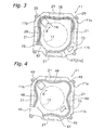
- Fig. 3 is a bottom view showing the interior of the indoor unit 1.
- a bell mouth 18 is disposed in the interior of the casing 11 which faces the air suction port 20, and a centrifugal fan 17 for taking air in from the air suction port 20 and discharging air on the sides thereof is disposed above the bell mouth 18.
- a cross fin type heat exchanger 27 for exchanging heat with the air discharged from the centrifugal fan 17 is disposed between the centrifugal fan 17 and the air discharge port 21 such that it surrounds the centrifugal fan 17.
- the heat exchanger 27 is a member in which one cross fin type heat exchange unit 27a has been bent, and includes two concave portions 28 that are formed so that they are near the outer circumference of the centrifugal fan 17, and two convex portions 29 that are formed so that they extend away from the outer circumference of the centrifugal fan 17, all of which extend along the direction of rotation of the centrifugal fan 17 (hereinafter referred to as the rotational direction R).
- the heat exchanger 27 is connected to a outdoor unit refrigerant line (not shown in the figures) by a refrigerant line connector 26.
- each convex portion 29 is disposed between two of the air discharge ports 21, i.e., disposed such that they project out to near the wall surfaces of the rectangular comer portions 11b of the casing 11.
- An electric component box 16 which stores the electric components needed for operating the indoor unit 1 (air conditioner) is disposed in a space formed by one of the convex portions 29 of the heat exchanger 27 (in the present embodiment, the direction of rotation R side of the refrigerant line connector 26 in Fig. 3) and the outer circumference of the centrifugal fan 17.
- a convex portion 29 is not formed in one of the rectangular comer portions 11b of the casing 11 (in the present embodiment, the opposite side of the direction of rotation R of the refrigerant line connector 26 in Fig. 3), but rather has a drain pump 15 for discharging condensed water that is produced during heat exchange.
- the special characteristics of the air conditioner of the present embodiment are as follows:
- the concave portions 28 and the convex portions 29 are formed opposite two sides of the rectangular casing 11 but may be formed on the other two sides of the casing 11.
- Fig. 4 shows a heat exchanger 47 in which the concave portions 48 and the convex portions 49 have been formed opposite each side of the rectangular casing 11.
- the drain pump 15 is disposed in a space formed by one of the convex portions 49 of the heat exchanger 47 (in the present embodiment, on the opposite side of the direction of rotation R of the refrigerant line connector 46 in Fig. 4) and the outer circumferential portion of the centrifugal fan 17.
- the effective length of the heat exchanger can be extended even further.
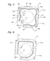
- the drain pump 15 is disposed in the space formed by the convex portion 49 adjacent to the refrigerant line connector 46 and the outer circumferential portion of the centrifugal fan 17.
- the drain pump 15 is disposed in a space between the refrigerant line connector 46 and the outer circumferential portion of the centrifugal fan 17.
- line construction during the installation of the indoor unit will be simplified because the water drain line for discharging water from the drain pump 15 can be disposed in the same location as the refrigerant line.
- the concave portions 28 and the convex portions 29 are formed opposite two sides of the rectangular casing 11 but two straight sloped portions 90a, 90b that are inclined away from the sides of the casing 11 may be formed on the other two sides thereof.
- Fig. 7 shows a heat exchanger 87.
- the heat exchanger 87 is one cross fin type of heat exchanging unit 87a that has been bent into shape, and includes a first concave portion 88a that is formed such that it is opposite the side of the casing 11 adjacent to a refrigerant line connector 86 and near the outer circumferential portion of the centrifugal fan 17, a first convex portion 89a that is formed such that it is opposite the comer 11b of the casing 11 adjacent to the first concave portion 88a and extends away from the outer circumferential portion of the centrifugal fan 17, a second concave portion 88b that is formed such that it is opposite the side of the casing 11 adjacent to the first convex portion 89a and near the outer circumferential portion of the centrifugal fan 17, a second convex portion 88b that is formed such that it is opposite the comer 11b of the casing 11 adjacent to the second concave portion 88b and extends away from the outer circumferential portion of the centrifugal fan 17,
- a bent portion 91 is formed opposite the comer 11b of the casing 11 that is between the first sloped portion 90a and the second sloped portion 90b.
- a drain pump 15 is disposed between the bent portion 91 and the corner 11b in which the bend portion 91 was provided.
- the bend portion 91 has a straight shape that is bent such that it extends along the side of drain pump 15.
- the sloped portions 90a, 90b extend such that they are inclined with respect to the sides of the casing 11, they increase the effective length of the heat exchanger 67 when compared to situations in which they extend parallel to the sides of the casing 11 like that of the conventional heat exchanger 67.
- the bent portion 91 extends along the side of the drain pump 15, it increases the effective length of the heat exchanger when compared to situations in which it is bent along the outer circumference of the centrifugal fan like the conventional heat exchanger 67.
- the effective length of the heat exchanger 87 can be increased when compared with the conventional heat exchanger 67 because it has concave portions 89a, 89b, and convex portions 88a, 88b.
- the effective length of the heat exchanger 87 can be increased when compared to the heat exchanger 27 of the first embodiment because it has two sloped portions 90a, 90b and a bent portion 91.
- the present invention is applied to an air conditioner that is built into a ceiling.
- the present invention can also be applied to an air conditioner that is hung from the ceiling.
- the effective length of a heat exchanger can be increased without enlarging the size of the casing.
Landscapes
- Engineering & Computer Science (AREA)
- Chemical & Material Sciences (AREA)
- Combustion & Propulsion (AREA)
- Mechanical Engineering (AREA)
- General Engineering & Computer Science (AREA)
- Physics & Mathematics (AREA)
- Thermal Sciences (AREA)
- Air Filters, Heat-Exchange Apparatuses, And Housings Of Air-Conditioning Units (AREA)
- Air-Conditioning Room Units, And Self-Contained Units In General (AREA)
Abstract
The present invention is an air conditioner that is built into or hung from a
ceiling and which employs a cross fin type of heat exchanger, in which the effective
length of the heat exchanger is increased without increasing the size of the casing of the
indoor uni t.
An indoor unit 1 has a casing 11 that supports the components of the indoor
unit 1 and in which an air suction port 20 and air discharge ports 21 are formed, a
centrifugal fan 17 disposed inside the casing 11 for taking in air from the air suction
port 20 and discharging air out to the sides thereof, and a cross fin type of heat
exchanger 27 for exchanging heat with the air discharged from the centrifugal fan 17
and disposed so that it surrounds the centrifugal fan 17. The heat exchanger 27 has a
plurality of concave portions 28 that are formed such that they are near the outer
circumferential portion of the centrifugal fan 17, and a plurality of convex portions 29
that are formed such that the extend away from the outer circumferential portion of the
centrifugal fan 17.
Description
The present invention relates to an air conditioner, and more particularly to an
air conditioner either built into or hanging from a ceiling.
An air conditioner is mainly constructed of an outdoor unit that has a
compressor and a heat exchanger, and an indoor unit that has a centrifugal fan and a
heat exchanger. The indoor unit can be any one of a variety of types, such as one
mounted on a wall, built into a ceiling, hanging from the ceiling or the like.
Indoor units that are built into or hanging from a ceiling are primarily
composed of a casing that has an air suction port and a air discharge port on the bottom
surface thereof, a centrifugal fan disposed inside the casing, and a heat exchanger
disposed such that it surrounds the centrifugal fan. In this type of indoor unit, indoor
air is taken into the interior of the casing from the air suction port, and is then blown by
the centrifugal fan to the outer circumferential portion thereof. Then, the air blown to
the outer circumferential portion of the centrifugal fan exchanges heat with the heat
exchanger disposed around the centrifugal fan, and is then supplied to the interior of the
room from the air discharge port.
Conventionally, many heat exchangers disposed in the casing of an indoor unit
are cross fin type, and are bent into an approximate rectangular or circular shape such
that they surround the centrifugal fan in a plane view.
With this type of heat exchanger, it is desirable to increase the effective length
of the heat exchanger and to improve the heat exchanging performance of the air
conditioner.
The size of the casing of the indoor unit can be made larger in order to increase
the effective length of the heat exchanger. However, from a practical point of view, it
is not desirable for the size of a conventional casing to be enlarged, and this is the main
cause of an increase in costs.
An object of the present invention is to increase the effective length of a cross
fin type of heat exchanger employed in an air conditioner that is built into or hung from
a ceiling, without increasing the size of the casing of the indoor unit.
The air conditioner disclosed in claim 1 is an air conditioner that is built in or
hung from a ceiling and which includes a casing having an air suction port for taking in
air into the interior thereof and air discharge ports for discharging air to the exterior
thereof, a centrifugal fan disposed in the interior of the casing and between the air
suction port and the air discharge ports, and a cross fin type of heat exchanger disposed
between the centrifugal fan and the air discharge ports and inside the casing such that it
surrounds the centrifugal fan. The heat exchanger has a plurality of convex portions
that are formed such that they extend away from an outer circumferential portion of the
centrifugal fan, and a plurality of concave portions that are formed such that they are
near the outer circumferential portion of the centrifugal fan.
In this air conditioner, indoor air is taken into the interior of the casing from the
air suction port by means of the centrifugal fan, and is then blown out to the outer
circumference of the centrifugal fan. Then the air blown out from the centrifugal fan
exchanges heat with a cross fin type of heat exchanger disposed such that it surrounds
the centrifugal fan, and afterward the air is discharged from the air discharge port and
supplied to the interior of the room. The cross fin type of heat exchanger installed here
has a plurality of convex portions formed such that they extend away from the outer
circumferential portion of the centrifugal fan and a plurality of convex portions formed
such that they are near the circumferential portion of the centrifugal fan. Because of
this, the effective length of the heat exchanger is increased when compared to a heat
exchanger installed in an air conditioner having a casing that is of a conventional size.
Thus, the effective length of the heat exchanger can be increased without making the
size of the casing larger.
The air conditioner disclosed in claim 2 is the air conditioner of claim 1, in
which the concave portions are disposed in positions opposite at least the air discharge
ports.
In this air conditioner, the heat exchanger is not too close to the air discharge
ports, and the air discharge ports are not narrowed, because the concave portions of the
heat exchanger are provided in positions opposite at least the air discharge ports. In
other words, the surface area of the openings of air discharge ports are maintained, the
ability to blow air out therefrom is not worsened, and the effective length of the heat
exchanger can be increased.
The air conditioner disclosed in claim 3 is the air conditioner of claims 1 or 2,
in which the casing is approximately rectangular in shape, the plurality of air discharge
ports are disposed in positions opposite each side of the casing, and the plurality of
convex portions are disposed in positions that are opposite at least the comers of the
casing.
In this air conditioner, the space in the casing can be effectively used because
the convex portions of the heat exchanger are provided in positions opposite the comers
which have a comparatively large space.
The air conditioner disclosed in claim 4 is the air conditioner of claims 2 or 3,
in which the heat exchanger further includes sloped portions that extend from one
corner of the casing to an adjacent comer and are inclined with respect to the sides of
the casing.
In this air conditioner, the heat exchanger has sloped portions that extend such
that they are inclined with respect to the sides of the casing. On the other hand, a
conventional heat exchanger that is disposed in an air conditioner having a conventional
size casing extends parallel with respect to the sides of the casing. In other words, the
effective length of the heat exchanger of the present invention is greater than a
conventional heat exchanger. Thus, the effective length of the heat exchanger can be
increased without increasing the size of the casing.
The air conditioner disclosed in claim 5 is the air conditioner of claims 3 or 4,
in which a drain pump for discharging drain water generated by the heat exchanger to
the exterior of the casing is disposed in a position between the heat exchanger inside the
casing and one comer of the casing.
In this air conditioner, the space in the casing can be effectively used because
the drain pump is provided in a corner of the casing having a comparatively large space.
The air conditioner disclosed in claim 6 is the air conditioner of claim 5, in
which the heat exchanger further includes a bent portion that extends along the drain
pump in a position opposite the corner in which the drain pump is disposed.
In this air conditioner, the effective length of the heat exchanger can be
increased when compared to the shape of a conventional heat exchanger bent along the
outer circumferential portion of a centrifugal fan in the comers of the casing of the air
conditioner, because the shape of the heat exchanger is bent in the corner of the casing
in which the drain pump is disposed and along the drain pump.
The air conditioner disclosed in claim 7 is the air conditioner in any of claims 1
to 6, in which the heat exchanger is a cross fin type of heat exchange unit that is bent.
In this air conditioner, the heat exchanger is constructed from one cross fin type
of heat exchange unit. In other words, the heat exchanger is not constructed from a
plurality of heat exchange units, but rather is one cross fin type of heat exchange unit in
which a plurality of concave portions and a plurality of convex portions have been
formed therein. Thus, it is not necessary to branch the refrigerant lines of the heat
exchanger, and the structure thereof can be simplified.
The air conditioner disclosed in claim 8 is the air conditioner of any of claims 1
to 7, in which an electric component box that stores electric components is disposed in a
position between a convex portion of the heat exchanger and the outer circumferential
portion of the centrifugal fan.
In this air conditioner, the space between the convex portion of the heat
exchanger and the outer circumferential portion of the centrifugal fan is bigger than
other portions. Thus, the electrical components needed to operate the air conditioner
can be assembled in the electrical component box, stored therein, and disposed in this
space.
An outer perspective view (ceiling omitted) of an indoor unit 1 of an air
conditioner according to a first embodiment of the present invention is shown in Fig. 1.
The indoor unit 1 is a type that is built into a ceiling, and has a casing 11 that is built
into the ceiling. The indoor unit 1 is installed indoors, and takes in indoor air from an
air intake 20 into the interior of the casing 11. After conditioning the air by heat
exchange, the air is discharged from the casing 11 through an air discharge port 21 and
supplied to the indoor space.
Next, a description of the casing 11 will be provided.
The casing 11 is a member for supporting the components of the indoor unit 1
therein. The casing 11 has a substantially rectangular solid shaped exterior, and a
substantially rectangular shaped decoration panel 11a on the bottom thereof. An air
suction port 20 is formed in the middle of the bottom portion of the casing 11, and four
rectangular air discharge ports 21 are formed around the outer circumference of the air
suction port 20 such that they are opposite each side thereof.
Fig. 2 is a lateral cross sectional view of the indoor unit 1, and Fig. 3 is a
bottom view showing the interior of the indoor unit 1. A bell mouth 18 is disposed in
the interior of the casing 11 which faces the air suction port 20, and a centrifugal fan 17
for taking air in from the air suction port 20 and discharging air on the sides thereof is
disposed above the bell mouth 18. A cross fin type heat exchanger 27 for exchanging
heat with the air discharged from the centrifugal fan 17 is disposed between the
centrifugal fan 17 and the air discharge port 21 such that it surrounds the centrifugal fan
17.
Next, a description of the heat exchanger 27 will be provided.
As shown in Fig. 3, the heat exchanger 27 is a member in which one cross fin
type heat exchange unit 27a has been bent, and includes two concave portions 28 that
are formed so that they are near the outer circumference of the centrifugal fan 17, and
two convex portions 29 that are formed so that they extend away from the outer
circumference of the centrifugal fan 17, all of which extend along the direction of
rotation of the centrifugal fan 17 (hereinafter referred to as the rotational direction R).
The heat exchanger 27 is connected to a outdoor unit refrigerant line (not shown in the
figures) by a refrigerant line connector 26.
Here, the two concave portions 28 are disposed in positions that face two of the
air discharge ports 21, and are disposed such that they do not obstruct the air discharge
ports 21 in the plane view of the casing 11. In addition, each convex portion 29 is
disposed between two of the air discharge ports 21, i.e., disposed such that they project
out to near the wall surfaces of the rectangular comer portions 11b of the casing 11.
An electric component box 16 which stores the electric components needed for
operating the indoor unit 1 (air conditioner) is disposed in a space formed by one of the
convex portions 29 of the heat exchanger 27 (in the present embodiment, the direction
of rotation R side of the refrigerant line connector 26 in Fig. 3) and the outer
circumference of the centrifugal fan 17.
In addition, a convex portion 29 is not formed in one of the rectangular comer
portions 11b of the casing 11 (in the present embodiment, the opposite side of the
direction of rotation R of the refrigerant line connector 26 in Fig. 3), but rather has a
drain pump 15 for discharging condensed water that is produced during heat exchange.
As shown by the arrow W in Fig. 2, when the centrifugal fan 17 is rotated,
indoor air is drawn into the interior of the indoor unit 1 from the air suction port 20.
The air drawn therein, as shown by the arrow X in Fig. 2, is discharged to the outer
circumferential portion of the centrifugal fan 17. The air discharged to the outer
circumferential portion of the centrifugal fan 17, as shown by the arrow Y in Fig. 2,
exchanges heat with the heat exchanger 27 disposed on the outer circumferential side of
the centrifugal fan 17, and is discharged to the interior of the room from the air
discharge ports 21 provided in the bottom portion of the casing 11.
As described above, the special characteristics of the air conditioner of the
present embodiment are as follows:
In the aforementioned embodiment, the concave portions 28 and the convex
portions 29 are formed opposite two sides of the rectangular casing 11 but may be
formed on the other two sides of the casing 11. Fig. 4 shows a heat exchanger 47 in
which the concave portions 48 and the convex portions 49 have been formed opposite
each side of the rectangular casing 11. In the present embodiment, the drain pump 15
is disposed in a space formed by one of the convex portions 49 of the heat exchanger 47
(in the present embodiment, on the opposite side of the direction of rotation R of the
refrigerant line connector 46 in Fig. 4) and the outer circumferential portion of the
centrifugal fan 17.
In the present embodiment, the effective length of the heat exchanger can be
extended even further.
In the second embodiment, the drain pump 15 is disposed in the space formed
by the convex portion 49 adjacent to the refrigerant line connector 46 and the outer
circumferential portion of the centrifugal fan 17. However, as shown in Fig. 5, in the
present embodiment the drain pump 15 is disposed in a space between the refrigerant
line connector 46 and the outer circumferential portion of the centrifugal fan 17.
In the present embodiment, line construction during the installation of the
indoor unit will be simplified because the water drain line for discharging water from
the drain pump 15 can be disposed in the same location as the refrigerant line.
In the first embodiment, the concave portions 28 and the convex portions 29
are formed opposite two sides of the rectangular casing 11 but two straight sloped
portions 90a, 90b that are inclined away from the sides of the casing 11 may be formed
on the other two sides thereof. Fig. 7 shows a heat exchanger 87. Like the heat
exchanger 27 of the first embodiment, the heat exchanger 87 is one cross fin type of
heat exchanging unit 87a that has been bent into shape, and includes a first concave
portion 88a that is formed such that it is opposite the side of the casing 11 adjacent to a
refrigerant line connector 86 and near the outer circumferential portion of the
centrifugal fan 17, a first convex portion 89a that is formed such that it is opposite the
comer 11b of the casing 11 adjacent to the first concave portion 88a and extends away
from the outer circumferential portion of the centrifugal fan 17, a second concave
portion 88b that is formed such that it is opposite the side of the casing 11 adjacent to
the first convex portion 89a and near the outer circumferential portion of the centrifugal
fan 17, a second convex portion 88b that is formed such that it is opposite the comer
11b of the casing 11 adjacent to the second concave portion 88b and extends away from
the outer circumferential portion of the centrifugal fan 17, a straight first sloped portion
90a that extends such that it is inclined with respect to the side of the casing 11 adjacent
to the second convex portion 88b, and a straight second sloped portion 90b that extends
such that it is inclined with respect to the side of the casing 11 adjacent to the first
sloped portion 90a. A bent portion 91 is formed opposite the comer 11b of the casing
11 that is between the first sloped portion 90a and the second sloped portion 90b. A
drain pump 15 is disposed between the bent portion 91 and the corner 11b in which the
bend portion 91 was provided. The bend portion 91 has a straight shape that is bent
such that it extends along the side of drain pump 15.
Because the sloped portions 90a, 90b extend such that they are inclined with
respect to the sides of the casing 11, they increase the effective length of the heat
exchanger 67 when compared to situations in which they extend parallel to the sides of
the casing 11 like that of the conventional heat exchanger 67. In addition, because the
bent portion 91 extends along the side of the drain pump 15, it increases the effective
length of the heat exchanger when compared to situations in which it is bent along the
outer circumference of the centrifugal fan like the conventional heat exchanger 67.
In the present embodiment, like with the heat exchanger 27 of the first
embodiment, the effective length of the heat exchanger 87 can be increased when
compared with the conventional heat exchanger 67 because it has concave portions 89a,
89b, and convex portions 88a, 88b. In addition, the effective length of the heat
exchanger 87 can be increased when compared to the heat exchanger 27 of the first
embodiment because it has two sloped portions 90a, 90b and a bent portion 91.
In the aforementioned embodiments, the present invention is applied to an air
conditioner that is built into a ceiling. However, the present invention can also be
applied to an air conditioner that is hung from the ceiling.
According to the present invention, the effective length of a heat exchanger can
be increased without enlarging the size of the casing.
Claims (8)
- An air conditioner built into or hung from a ceiling, comprising:wherein the heat exchanger (27, 47, 87) has a plurality of convex portions (29, 49, 89a, 89b) that are formed such that they extend away from an outer circumferential portion of the centrifugal fan (17), and a plurality of concave portions (28, 48, 88a, 88b) that are formed such that they are near the outer circumferential portion of the centrifugal fan (17).a casing (11) having an air suction port (20) for taking in air into the interior thereof and air discharge ports (21) for discharging air to the exterior thereof;a centrifugal fan (17) disposed in the interior of the casing (11) and between the air suction port (20) and the air discharge ports (21); anda cross fin type of heat exchanger (27, 47, 87) disposed between the centrifugal fan (17) and the air discharge ports (21) and inside the casing (11) so that it surrounds the centrifugal fan (17);
- The air conditioner according to claim 1, wherein the concave portions (28, 48, 88a, 88b) are disposed in positions opposite at least the air discharge ports (21).
- The air conditioner according to claims 1 or 2, wherein
the casing (11) is approximately rectangular in shape;
the plurality of air discharge ports (21) are disposed in positions opposite each side of the casing (11); and
the plurality of convex portions (29, 49, 89a, 89b) are disposed in positions that are opposite at least comers 11b of the casing (11). - The air conditioner according to claim 3, wherein the heat exchanger (87) further includes sloped portions (90a, 90b) that extend from one comer (11b) of the casing (11) to an adjacent comer (11b) and are inclined with respect to the sides of the casing (11).
- The air conditioner according to claims 3 or 4, wherein a drain pump (15) for discharging drain water generated by the heat exchanger (27, 87) to the exterior of the casing (11) is disposed in a position between the heat exchanger (27, 87) inside the casing (11) and one comer (11b) of the casing (11).
- The air conditioner according to claim 5, wherein the heat exchanger (87) further includes a bent portion (91) that extends along the drain pump (15) in a position opposite the comer (11b) in which the drain pump (15) is disposed.
- The air conditioner according to any of claims 1 to 6, wherein the heat exchanger (27, 47, 87) is a cross fin type of heat exchange unit (27a, 47a, 87a) that is bent.
- The air conditioner according to any of claims 1 to 7, wherein an electric component box (16) that stores electric components is disposed in a position between a convex portions (29, 49, 89a, 89b) of the heat exchanger (27, 47, 87) and the outer circumferential portion of the centrifugal fan (17).
Applications Claiming Priority (3)
| Application Number | Priority Date | Filing Date | Title |
|---|---|---|---|
| JP2001217821A JP3651417B2 (en) | 2001-07-18 | 2001-07-18 | Air conditioner |
| JP2001217821 | 2001-07-18 | ||
| PCT/JP2002/003359 WO2003008870A1 (en) | 2001-07-18 | 2002-04-03 | Air conditioner |
Publications (2)
| Publication Number | Publication Date |
|---|---|
| EP1408285A1 true EP1408285A1 (en) | 2004-04-14 |
| EP1408285A4 EP1408285A4 (en) | 2007-03-28 |
Family
ID=19052085
Family Applications (1)
| Application Number | Title | Priority Date | Filing Date |
|---|---|---|---|
| EP02714447A Withdrawn EP1408285A4 (en) | 2001-07-18 | 2002-04-03 | AIR CONDITIONER |
Country Status (6)
| Country | Link |
|---|---|
| US (1) | US6877331B2 (en) |
| EP (1) | EP1408285A4 (en) |
| JP (1) | JP3651417B2 (en) |
| CN (2) | CN1198097C (en) |
| AU (1) | AU2002246337B2 (en) |
| WO (1) | WO2003008870A1 (en) |
Cited By (1)
| Publication number | Priority date | Publication date | Assignee | Title |
|---|---|---|---|---|
| EP1548372A4 (en) * | 2002-08-30 | 2008-05-14 | Toshiba Carrier Corp | APPARATUS FOR AIR CONDITIONING IN CEILING |
Families Citing this family (17)
| Publication number | Priority date | Publication date | Assignee | Title |
|---|---|---|---|---|
| JP2000046360A (en) * | 1998-07-29 | 2000-02-18 | Hitachi Ltd | Ceiling-mounted indoor unit |
| KR100565593B1 (en) * | 2003-06-04 | 2006-03-30 | 엘지전자 주식회사 | Supply / exhaust direct ventilation / air conditioning system |
| KR100519310B1 (en) * | 2003-06-11 | 2005-10-07 | 엘지전자 주식회사 | air-conditioner system with ventilation |
| KR20060015123A (en) * | 2004-08-13 | 2006-02-16 | 위니아만도 주식회사 | Ceiling air conditioner |
| KR101229343B1 (en) * | 2005-12-29 | 2013-02-05 | 삼성전자주식회사 | Ceiling Type Air Conditioner |
| JP2007205619A (en) * | 2006-02-01 | 2007-08-16 | Mitsubishi Electric Corp | Indoor unit of air conditioner and arrangement structure thereof |
| JP4341713B2 (en) * | 2007-09-12 | 2009-10-07 | ダイキン工業株式会社 | Air conditioner indoor unit |
| FR2947040B1 (en) * | 2009-06-23 | 2014-01-03 | Cinier Radiateurs | REVERSIBLE RADIATOR |
| JP5267690B2 (en) * | 2012-02-03 | 2013-08-21 | ダイキン工業株式会社 | Indoor unit |
| CN104807079B (en) * | 2014-08-29 | 2018-04-27 | 青岛海尔空调器有限总公司 | A kind of wall-hanging air conditioner |
| JP6458984B2 (en) * | 2014-10-10 | 2019-01-30 | 株式会社富士通ゼネラル | Embedded ceiling air conditioner |
| KR101900484B1 (en) * | 2015-01-23 | 2018-09-20 | 삼성전자주식회사 | Air conditioner |
| JP6363033B2 (en) * | 2015-02-27 | 2018-07-25 | 日立ジョンソンコントロールズ空調株式会社 | Air conditioner indoor unit and air conditioner equipped with the same |
| EP3614065A4 (en) * | 2017-05-24 | 2020-04-15 | Daikin Industries, Ltd. | INTERIOR UNIT FOR AIR CONDITIONING |
| CN109425032B (en) * | 2017-06-23 | 2022-02-15 | 大金工业株式会社 | Indoor unit of air conditioner |
| CN111936797B (en) * | 2018-03-30 | 2022-08-02 | 富士通将军股份有限公司 | Ceiling embedded air conditioner |
| CN109751666B (en) * | 2019-01-14 | 2022-03-29 | 青岛海尔空调电子有限公司 | Be applied to heat exchanger and card formula air conditioner of card formula air conditioner |
Family Cites Families (10)
| Publication number | Priority date | Publication date | Assignee | Title |
|---|---|---|---|---|
| JPS62162830A (en) * | 1986-01-13 | 1987-07-18 | Matsushita Electric Ind Co Ltd | air conditioner |
| JPH055536A (en) * | 1990-11-07 | 1993-01-14 | Daikin Ind Ltd | Air conditioner |
| JPH0949640A (en) * | 1995-08-09 | 1997-02-18 | Sanyo Electric Co Ltd | Air conditioner |
| JP3606968B2 (en) | 1995-11-08 | 2005-01-05 | 三菱電機株式会社 | Air conditioner |
| JP3593418B2 (en) * | 1996-07-03 | 2004-11-24 | 東芝キヤリア株式会社 | Ceiling cassette type air conditioner |
| JPH11148711A (en) * | 1997-11-14 | 1999-06-02 | Mitsubishi Heavy Ind Ltd | Ceiling-mounted air conditioner |
| JP2000046360A (en) * | 1998-07-29 | 2000-02-18 | Hitachi Ltd | Ceiling-mounted indoor unit |
| JP2000121089A (en) * | 1998-10-20 | 2000-04-28 | Hitachi Ltd | Air conditioner |
| JP2000220859A (en) * | 1999-02-01 | 2000-08-08 | Hitachi Ltd | Air conditioner |
| JP2001124359A (en) * | 1999-10-26 | 2001-05-11 | Hitachi Ltd | Air conditioner |
-
2001
- 2001-07-18 JP JP2001217821A patent/JP3651417B2/en not_active Expired - Fee Related
-
2002
- 2002-03-08 CN CNB021069328A patent/CN1198097C/en not_active Expired - Fee Related
- 2002-03-08 CN CN02207602U patent/CN2532406Y/en not_active Expired - Lifetime
- 2002-04-03 US US10/363,651 patent/US6877331B2/en not_active Expired - Fee Related
- 2002-04-03 EP EP02714447A patent/EP1408285A4/en not_active Withdrawn
- 2002-04-03 AU AU2002246337A patent/AU2002246337B2/en not_active Ceased
- 2002-04-03 WO PCT/JP2002/003359 patent/WO2003008870A1/en not_active Ceased
Cited By (1)
| Publication number | Priority date | Publication date | Assignee | Title |
|---|---|---|---|---|
| EP1548372A4 (en) * | 2002-08-30 | 2008-05-14 | Toshiba Carrier Corp | APPARATUS FOR AIR CONDITIONING IN CEILING |
Also Published As
| Publication number | Publication date |
|---|---|
| AU2002246337B2 (en) | 2004-03-18 |
| US20040093886A1 (en) | 2004-05-20 |
| US6877331B2 (en) | 2005-04-12 |
| CN1198097C (en) | 2005-04-20 |
| CN1397773A (en) | 2003-02-19 |
| CN2532406Y (en) | 2003-01-22 |
| JP3651417B2 (en) | 2005-05-25 |
| WO2003008870A1 (en) | 2003-01-30 |
| JP2003028452A (en) | 2003-01-29 |
| EP1408285A4 (en) | 2007-03-28 |
Similar Documents
| Publication | Publication Date | Title |
|---|---|---|
| US6877331B2 (en) | Air conditioner | |
| JP2003254565A (en) | Outdoor unit for air conditioner | |
| KR20040092471A (en) | Front suction/discharge type outdoor unit for air-conditioner and outdoor unit installation system using it | |
| JP2005024223A (en) | Indoor unit of air conditioner and seal plate of indoor heat exchanger | |
| JP2006071162A (en) | Air conditioner | |
| JP2011158108A (en) | Outdoor unit for air conditioner | |
| US6314748B1 (en) | Window-type of integrated air-conditioner | |
| JP4986696B2 (en) | Refrigeration air conditioner | |
| JP2871562B2 (en) | Wall-mounted air conditioner | |
| JPH08285321A (en) | Integrated air conditioner | |
| JPH09210405A (en) | Ceiling-mounted air conditioner | |
| JP2003106564A (en) | Outdoor unit of air conditioner | |
| JPH0949640A (en) | Air conditioner | |
| JP3193134B2 (en) | Air conditioner | |
| EP0789196A2 (en) | Air conditioner having eccentrically-disposed fan | |
| WO2021205499A1 (en) | Outdoor unit | |
| JP2003035437A (en) | Air conditioner outdoor unit | |
| JP2008045780A (en) | Indoor unit of air conditioner | |
| JP2018025357A (en) | Indoor unit and air conditioner | |
| KR20010037825A (en) | window type air-conditioner for reducing noise | |
| JP2006084051A (en) | Refrigeration equipment outdoor unit | |
| JP7258053B2 (en) | Bottom panel and outdoor unit of air conditioner | |
| JPH09145100A (en) | Air conditioner outdoor unit | |
| JP3792137B2 (en) | Air conditioner outdoor unit | |
| CN211084243U (en) | Air duct structure of kitchen air conditioner |
Legal Events
| Date | Code | Title | Description |
|---|---|---|---|
| PUAI | Public reference made under article 153(3) epc to a published international application that has entered the european phase |
Free format text: ORIGINAL CODE: 0009012 |
|
| 17P | Request for examination filed |
Effective date: 20030403 |
|
| AK | Designated contracting states |
Kind code of ref document: A1 Designated state(s): AT BE CH CY DE DK ES FI FR GB GR IE IT LI LU MC NL PT SE TR |
|
| A4 | Supplementary search report drawn up and despatched |
Effective date: 20070226 |
|
| 17Q | First examination report despatched |
Effective date: 20080422 |
|
| STAA | Information on the status of an ep patent application or granted ep patent |
Free format text: STATUS: THE APPLICATION IS DEEMED TO BE WITHDRAWN |
|
| 18D | Application deemed to be withdrawn |
Effective date: 20110315 |