EP1408196A2 - Method of forming cooling apertures in airfoil-shaped blades - Google Patents
Method of forming cooling apertures in airfoil-shaped blades Download PDFInfo
- Publication number
- EP1408196A2 EP1408196A2 EP03256253A EP03256253A EP1408196A2 EP 1408196 A2 EP1408196 A2 EP 1408196A2 EP 03256253 A EP03256253 A EP 03256253A EP 03256253 A EP03256253 A EP 03256253A EP 1408196 A2 EP1408196 A2 EP 1408196A2
- Authority
- EP
- European Patent Office
- Prior art keywords
- airfoil
- water jet
- apertures
- nozzle head
- directing
- Prior art date
- Legal status (The legal status is an assumption and is not a legal conclusion. Google has not performed a legal analysis and makes no representation as to the accuracy of the status listed.)
- Withdrawn
Links
Images

Classifications
-
- F—MECHANICAL ENGINEERING; LIGHTING; HEATING; WEAPONS; BLASTING
- F01—MACHINES OR ENGINES IN GENERAL; ENGINE PLANTS IN GENERAL; STEAM ENGINES
- F01D—NON-POSITIVE DISPLACEMENT MACHINES OR ENGINES, e.g. STEAM TURBINES
- F01D5/00—Blades; Blade-carrying members; Heating, heat-insulating, cooling or antivibration means on the blades or the members
- F01D5/12—Blades
- F01D5/14—Form or construction
- F01D5/18—Hollow blades, i.e. blades with cooling or heating channels or cavities; Heating, heat-insulating or cooling means on blades
-
- B—PERFORMING OPERATIONS; TRANSPORTING
- B26—HAND CUTTING TOOLS; CUTTING; SEVERING
- B26F—PERFORATING; PUNCHING; CUTTING-OUT; STAMPING-OUT; SEVERING BY MEANS OTHER THAN CUTTING
- B26F3/00—Severing by means other than cutting; Apparatus therefor
- B26F3/004—Severing by means other than cutting; Apparatus therefor by means of a fluid jet
- B26F3/008—Energy dissipating devices therefor, e.g. catchers; Supporting beds therefor
-
- B—PERFORMING OPERATIONS; TRANSPORTING
- B24—GRINDING; POLISHING
- B24C—ABRASIVE OR RELATED BLASTING WITH PARTICULATE MATERIAL
- B24C1/00—Methods for use of abrasive blasting for producing particular effects; Use of auxiliary equipment in connection with such methods
- B24C1/04—Methods for use of abrasive blasting for producing particular effects; Use of auxiliary equipment in connection with such methods for treating only selected parts of a surface, e.g. for carving stone or glass
- B24C1/045—Methods for use of abrasive blasting for producing particular effects; Use of auxiliary equipment in connection with such methods for treating only selected parts of a surface, e.g. for carving stone or glass for cutting
-
- B—PERFORMING OPERATIONS; TRANSPORTING
- B24—GRINDING; POLISHING
- B24C—ABRASIVE OR RELATED BLASTING WITH PARTICULATE MATERIAL
- B24C3/00—Abrasive blasting machines or devices; Plants
- B24C3/32—Abrasive blasting machines or devices; Plants designed for abrasive blasting of particular work, e.g. the internal surfaces of cylinder blocks
- B24C3/325—Abrasive blasting machines or devices; Plants designed for abrasive blasting of particular work, e.g. the internal surfaces of cylinder blocks for internal surfaces, e.g. of tubes
-
- B—PERFORMING OPERATIONS; TRANSPORTING
- B23—MACHINE TOOLS; METAL-WORKING NOT OTHERWISE PROVIDED FOR
- B23P—METAL-WORKING NOT OTHERWISE PROVIDED FOR; COMBINED OPERATIONS; UNIVERSAL MACHINE TOOLS
- B23P2700/00—Indexing scheme relating to the articles being treated, e.g. manufactured, repaired, assembled, connected or other operations covered in the subgroups
- B23P2700/06—Cooling passages of turbine components, e.g. unblocking or preventing blocking of cooling passages of turbine components
-
- F—MECHANICAL ENGINEERING; LIGHTING; HEATING; WEAPONS; BLASTING
- F05—INDEXING SCHEMES RELATING TO ENGINES OR PUMPS IN VARIOUS SUBCLASSES OF CLASSES F01-F04
- F05B—INDEXING SCHEME RELATING TO WIND, SPRING, WEIGHT, INERTIA OR LIKE MOTORS, TO MACHINES OR ENGINES FOR LIQUIDS COVERED BY SUBCLASSES F03B, F03D AND F03G
- F05B2230/00—Manufacture
- F05B2230/10—Manufacture by removing material
-
- Y—GENERAL TAGGING OF NEW TECHNOLOGICAL DEVELOPMENTS; GENERAL TAGGING OF CROSS-SECTIONAL TECHNOLOGIES SPANNING OVER SEVERAL SECTIONS OF THE IPC; TECHNICAL SUBJECTS COVERED BY FORMER USPC CROSS-REFERENCE ART COLLECTIONS [XRACs] AND DIGESTS
- Y10—TECHNICAL SUBJECTS COVERED BY FORMER USPC
- Y10T—TECHNICAL SUBJECTS COVERED BY FORMER US CLASSIFICATION
- Y10T29/00—Metal working
- Y10T29/49—Method of mechanical manufacture
- Y10T29/49316—Impeller making
- Y10T29/49336—Blade making
- Y10T29/49339—Hollow blade
- Y10T29/49341—Hollow blade with cooling passage
-
- Y—GENERAL TAGGING OF NEW TECHNOLOGICAL DEVELOPMENTS; GENERAL TAGGING OF CROSS-SECTIONAL TECHNOLOGIES SPANNING OVER SEVERAL SECTIONS OF THE IPC; TECHNICAL SUBJECTS COVERED BY FORMER USPC CROSS-REFERENCE ART COLLECTIONS [XRACs] AND DIGESTS
- Y10—TECHNICAL SUBJECTS COVERED BY FORMER USPC
- Y10T—TECHNICAL SUBJECTS COVERED BY FORMER US CLASSIFICATION
- Y10T29/00—Metal working
- Y10T29/49—Method of mechanical manufacture
- Y10T29/49805—Shaping by direct application of fluent pressure
Definitions
- the present invention relates to methods for forming cooling apertures in airfoils for disposition in the hot gas path of a turbine and particularly relates to methods utilizing water jets for forming angled cooling apertures through the wall of the airfoil from within the airfoil.
- Film cooling of airfoils for use in the hot gas path of turbines requires the formation of cooling apertures through the walls of the airfoil.
- Higher gas turbine efficiencies and higher firing and operating temperatures have created a demand for film cooling schemes that can direct the cooling medium, e.g., air, to areas of the airfoils that are traditional hot spots or airfoil life-limiting regions.
- Traditional hot spots along the airfoil surfaces such as the leading edge and fillets, as well as along the trailing edge adjacent the fillets, can be cooled, provided the apertures are angled such that the hot spots are in the line-of-sight of the apertures.
- directed or angled cooling apertures are desirable for film cooling those regions.
- Prior processes for forming cooling apertures in an airfoil have included the use of EDM disposed within the airfoil forming the apertures from the inside of the airfoil out.
- Water jets have been used to form cooling apertures, with the water jets being directed from the outside of the airfoil toward the interior of the airfoil.
- Sharply angled apertures have not previously been formed by water jets due to the physical limitations and configurations of the water jet equipment. That is, portions of the nozzle, for example, the inner and outer band portions interfere with the water jet equipment when attempting to form sharply angled apertures through the airfoil from outside of the nozzle.
- the inner and outer band portions interfere with the positioning of the water jet equipment and preclude formation of the apertures from the outside to the inside of the nozzle using water jets. Accordingly, there is a need for a method of forming non-line-of-sight cooling apertures in airfoils for use in a turbine using water jet technology.
- a water jet nozzle head receivable through an opening through an end of the airfoil to position the nozzle within the airfoil such that the water jet emanating from the nozzle can form an angled aperture throughout the wall of the airfoil.
- the water jet nozzle head is disposed through the end opening into the interior cavity of the airfoil. The water jet is directed at an angle to form the angled aperture adjacent the opposite end of the airfoil.
- the water jet nozzle head is positioned along the interior of the airfoil wall such that the water jet emanating from the nozzle head forms a non-line-of-sight intersection with one of the band portions of the nozzle.
- non-line-of-sight is meant that, because of the physical limitations and configuration of water jet equipment and the configuration of the nozzle, a direct line-of-sight inclined aperture through the airfoil cannot be formed from outside the airfoil.
- a protective device e.g., a plate, is used as a backstop against which the water jet impinges.
- the device therefore precludes cutting of the band portion on axis with the aperture by the water jet.
- the nozzle head is disposed through an end opening of the airfoil opposite from the end of the airfoil through which the aperture is to be formed.
- the nozzle head directs the water jet emanating from the water jet nozzle head to form an angled aperture along a non-line-of-sight direction intersecting a portion of the other nozzle band.
- a protective device is utilized to protect the other band portion from being cut by the water jet.
- the inclined apertures through the airfoil wall may be formed utilizing water jet technology wherein the apertures do not have line-of-sight access externally of the airfoil.
- a method of forming apertures in an airfoil for use in a turbine wherein the airfoil has walls defining an airfoil shape and an interior cavity accessible through an opening at one end of the airfoil comprising the steps of disposing a water jet nozzle head through the one end opening to a location within the cavity of the airfoil and directing a water jet emanating from the nozzle head to cut one or more apertures through at least one wall of the airfoil.
- a method of forming apertures in a nozzle of a turbine having an airfoil wherein the airfoil has walls defining the airfoil shape, an interior cavity accessible through an opening at one end of the airfoil and inner and outer band portions extending laterally of the airfoil at opposite ends thereof comprising the steps of disposing a water jet nozzle head through the one end opening to a location within the cavity of the airfoil and directing a water jet emanating from the nozzle head to form one or more apertures through at least one wall of the airfoil along a line-of-sight intersecting one of the band portions.
- a nozzle for disposition within the hot gas path of a gas turbine.
- the nozzle 10 includes an airfoil 12 extending between inner and outer bands 14 and 16, respectively. It will be appreciated that nozzle 10 forms one of a plurality of nozzles in a circumferential array thereof for forming part of a stage of a turbine.
- air film cooling of nozzles has previously been provided by the formation of a plurality of apertures or openings in the walls of the airfoil for directing cooling air flowing within the nozzle through the holes or apertures to cool the traditional hot spots of a nozzle.
- a plurality of apertures 18, 20 and 22 are interspersed along the leading edge, the central portions of the sides of the airfoil and the trailing edge, respectively. It will be appreciated that, in use, certain of the apertures are angled to direct cooling air flow onto adjacent surfaces, for example, the inner or outer bands or the fillet regions of the nozzle. The angles of the apertures oftentimes preclude non-line-of-sight formation of the apertures by external equipment.
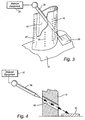
- a water jet equipment 27 having a water jet nozzle head 26 for reception within the interior of the nozzle 10 and specifically within the airfoil 12 of nozzle 10.
- the water jet equipment 27 may be of the type manufactured and sold by Huffman Corp., Clover, South Carolina. Basically, a conventional water jet provides a thin stream of water at high pressure, for example, in a range of 15,000 psi to 110,000 psi.
- the water is mixed with an abrasive material, for example, garnet or aluminum oxide to facilitate cutting the metal walls of the airfoil.
- the nozzle 10 includes one or more openings 25 and 29 through the opposite ends, respectively, of the airfoil 12 through which cooling air is supplied and exhausted in use.
- the water jet nozzle head 26 may be disposed through one of these openings and received within an interior cavity 31 ( Figure 3) of the airfoil.
- the nozzle head 26 is thus positioned for directing the water jet against the interior surface of the wall of the airfoil.
- the pressure of the water jet in conjunction with the abrasive material cuts the hole through the metal wall of the nozzle.
- a number of the apertures 18, 20 and 22 are preferably formed to direct cooling air jets onto other surfaces of the nozzle, for example, the inner and outer bands 14 and 16 and fillets 28.
- the water jet must form the aperture to the appropriate angle to enable the cooling air to effectively cool the adjacent traditional hot spots of the nozzle. Because of the requirement for airflow onto or along these traditional hot spots, the apertures are angled. The angles of the apertures, however, are such as to not allow line-of-sight access to the airfoil 12 from the outside of the airfoil using traditional machining methods.
- the apertures may be formed by cutting in non-line-of-sight directions, i.e., directions of the water jet which would intersect the surface intended to be cooled by cooling air flowing through the apertures.
- the nozzle head may be directed from the interior of the nozzle along a non-line-of-sight direction to form the angled apertures.
- a backstop or protective device 30 is deployed for protecting the portion of the nozzle which would otherwise be impacted by the water jet.
- the backstop 30 may comprise a protective plate temporarily secured to a portion of the nozzle, i.e., an outer or inner band, to receive, deflect and/or absorb the impact of the water jet once the water jet cuts through the wall of the nozzle forming the aperture at the required angle.
- the backstop 30 may be formed of a hard material such as carbide for durability and reuse.
- the backstop 30 may be formed of a metallic/plastic material for one-time usage or a material which will degrade over time and therefore have a predetermined number of uses.
- the backstop 30 may be shaped to pass about the nozzle and bands for temporary securement to the nozzle during the cutting of the apertures or may be clamped to the nozzle or to an ancillary fixture adjacent the nozzle.
- Various devices, e.g., backstops 30, may be used to slow the water jet.
- a sleeve not shown, may be disposed on a protective plate to dissipate a portion of the energy of the water jet before the water jet impacts the protective plate.
- the water jet essentially blasts through the metal material of the wall.
- the water jet after forming an initial opening, can be used to cut, i.e., circumscribe about a margin of the hole or aperture to enlarge the hole or aperture to the desired diameter or shape.
- various configurations of apertures can be provided as desired.
- the apertures may be circular, oval, round or cone-shaped or any other configuration within the capability of the water jet equipment.
Landscapes
- Engineering & Computer Science (AREA)
- Mechanical Engineering (AREA)
- Life Sciences & Earth Sciences (AREA)
- Forests & Forestry (AREA)
- General Engineering & Computer Science (AREA)
- Turbine Rotor Nozzle Sealing (AREA)
Abstract
Description
Claims (10)
- A method of forming apertures (18, 20, 22) in an airfoil (12) for use in a turbine wherein the airfoil has walls defining an airfoil shape and an interior cavity accessible through an opening (25) at one end of the airfoil, comprising the steps of:disposing a water jet nozzle head (26) through the one end opening to a location within the cavity of the airfoil; anddirecting a water jet emanating from said nozzle head to cut one or more apertures (18, 20, 22) through at least one wall of the airfoil.
- A method according to Claim 1 including directing the water jet against an interior wall portion of the airfoil to form the one or more apertures through the wall at an inclined angle relative to a surface of the airfoil.
- A method according to Claim 1 or 2 wherein the airfoil cavity is accessible through an opening (29) at an opposite end of the airfoil, and including disposing the water jet nozzle head through the opposite end opening to a location within the cavity of the airfoil and directing the water jet to cut one or more additional apertures through a wall of the airfoil.
- A method according to Claim 3 including directing the water jet against interior wall portions of the airfoil to form apertures through the wall at an inclined angle relative to a surface of the airfoil.
- A method according to Claim 3 including directing the water jet emanating from the nozzle head disposed through the opening (25) at one end of the airfoil against an interior wall portion of the airfoil to form an aperture through the wall angled toward an opposite end of the airfoil and directing the water jet emanating from the nozzle head disposed through said opposite end opening (29) against a further interior wall portion of the airfoil to form an aperture through the wall angled toward said one end of the airfoil.
- A method according to Claim 1 including directing the water jet to cut one or more apertures (18) along at least one side of the airfoil adjacent a leading edge thereof.
- A method according to Claim 1 including directing the water jet to cut one or more apertures (22) along at least one side of the airfoil adjacent a trailing edge thereof.
- A method according to Claim 1 including disposing a protective device (30) outside of the airfoil to provide a backstop for the water jet emerging through the formed aperture or apertures.
- A method of forming apertures in a nozzle of a turbine having an airfoil wherein the airfoil has walls defining the airfoil shape, an interior cavity (31) accessible through an opening at one end of the airfoil and inner and outer band portions (14, 16) extending laterally of the airfoil at opposite ends thereof, comprising the steps of:disposing a water jet nozzle head (26) through the one end opening to a location within the cavity of the airfoil; anddirecting a water jet emanating from the nozzle head to form one or more apertures (18, 20, 22) through at least one wall of the airfoil along a line-of-sight intersecting one of the band portions.
- A method according to Claim 9 including directing the water jet emanating from the nozzle head (26) disposed through said one end (25) opening against an interior wall portion of the airfoil to form an aperture through the wall portion angled toward an opposite end (29) of the airfoil and band portion and directing the water jet emanating from the nozzle head disposed through said opposite end opening against a further interior wall portion of the airfoil to form an aperture through the wall angled toward one end of the airfoil and the opposite band portion.
Applications Claiming Priority (2)
| Application Number | Priority Date | Filing Date | Title |
|---|---|---|---|
| US10/265,745 US20040064930A1 (en) | 2002-10-08 | 2002-10-08 | Method of forming cooling apertures in airfoil-shaped blades |
| US265745 | 2002-10-08 |
Publications (2)
| Publication Number | Publication Date |
|---|---|
| EP1408196A2 true EP1408196A2 (en) | 2004-04-14 |
| EP1408196A3 EP1408196A3 (en) | 2004-07-14 |
Family
ID=32030330
Family Applications (1)
| Application Number | Title | Priority Date | Filing Date |
|---|---|---|---|
| EP03256253A Withdrawn EP1408196A3 (en) | 2002-10-08 | 2003-10-03 | Method of forming cooling apertures in airfoil-shaped blades |
Country Status (3)
| Country | Link |
|---|---|
| US (1) | US20040064930A1 (en) |
| EP (1) | EP1408196A3 (en) |
| KR (1) | KR20040032070A (en) |
Cited By (2)
| Publication number | Priority date | Publication date | Assignee | Title |
|---|---|---|---|---|
| EP2135718A3 (en) * | 2008-06-18 | 2013-11-27 | Alstom Technology Ltd | Method for producing film cooling channels in a casing wall of a gas turbine and casing of a gas turbine |
| EP2769814A1 (en) | 2013-02-21 | 2014-08-27 | Waterjet Robotics AG | Method for drilling at least one hole in a workpiece |
Families Citing this family (12)
| Publication number | Priority date | Publication date | Assignee | Title |
|---|---|---|---|---|
| US6800829B1 (en) * | 2003-05-29 | 2004-10-05 | General Electric Company | Method and apparatus for repairing air-cooled airfoils |
| US7322796B2 (en) * | 2005-08-31 | 2008-01-29 | United Technologies Corporation | Turbine vane construction |
| KR101009369B1 (en) * | 2008-11-03 | 2011-01-19 | 정상구 | Washing machine for flush toilet |
| US9447689B2 (en) * | 2011-06-17 | 2016-09-20 | General Electric Company | Method of repairing a turbine nozzle segment in a turbine engine |
| US20140068939A1 (en) * | 2012-09-12 | 2014-03-13 | General Electric Company | Method for manufacturing an airfoil |
| US20140208771A1 (en) * | 2012-12-28 | 2014-07-31 | United Technologies Corporation | Gas turbine engine component cooling arrangement |
| US9278462B2 (en) * | 2013-11-20 | 2016-03-08 | General Electric Company | Backstrike protection during machining of cooling features |
| US20150165569A1 (en) * | 2013-12-18 | 2015-06-18 | Petya M. Georgieva | Repair of turbine engine components using waterjet ablation process |
| US20180128177A1 (en) * | 2016-11-07 | 2018-05-10 | General Electric Company | Method for forming a hole in an engine component |
| US10828718B2 (en) * | 2018-06-14 | 2020-11-10 | Raytheon Technologies Corporation | Installation of waterjet vent holes into vertical walls of cavity-back airfoils |
| US10919116B2 (en) | 2018-06-14 | 2021-02-16 | Raytheon Technologies Corporation | Installation of laser vent holes into vertical walls of cavity-back airfoils |
| CN109257757B (en) * | 2018-08-23 | 2021-11-09 | 全球能源互联网研究院有限公司 | Interference analysis system for electric power wireless private network |
Family Cites Families (3)
| Publication number | Priority date | Publication date | Assignee | Title |
|---|---|---|---|---|
| GB9723762D0 (en) * | 1997-11-12 | 1998-01-07 | Rolls Royce Plc | A method of coating a component |
| DE19917611A1 (en) * | 1999-04-19 | 2000-10-26 | Abb Alstom Power Ch Ag | Process for the production of cooling air bores and slots on parts of thermal turbomachinery which are exposed to hot gas |
| US6368060B1 (en) * | 2000-05-23 | 2002-04-09 | General Electric Company | Shaped cooling hole for an airfoil |
-
2002
- 2002-10-08 US US10/265,745 patent/US20040064930A1/en not_active Abandoned
-
2003
- 2003-10-03 EP EP03256253A patent/EP1408196A3/en not_active Withdrawn
- 2003-10-07 KR KR1020030069628A patent/KR20040032070A/en not_active Withdrawn
Cited By (4)
| Publication number | Priority date | Publication date | Assignee | Title |
|---|---|---|---|---|
| EP2135718A3 (en) * | 2008-06-18 | 2013-11-27 | Alstom Technology Ltd | Method for producing film cooling channels in a casing wall of a gas turbine and casing of a gas turbine |
| EP2769814A1 (en) | 2013-02-21 | 2014-08-27 | Waterjet Robotics AG | Method for drilling at least one hole in a workpiece |
| US9381663B2 (en) | 2013-02-21 | 2016-07-05 | Microwaterjet Ag | Method for drilling at least one hole into a workpiece |
| US9884403B2 (en) | 2013-02-21 | 2018-02-06 | Microwaterjet Ag | Machining arrangement for drilling at least one hole into a workpiece |
Also Published As
| Publication number | Publication date |
|---|---|
| EP1408196A3 (en) | 2004-07-14 |
| KR20040032070A (en) | 2004-04-14 |
| US20040064930A1 (en) | 2004-04-08 |
Similar Documents
| Publication | Publication Date | Title |
|---|---|---|
| EP1408196A2 (en) | Method of forming cooling apertures in airfoil-shaped blades | |
| US6307175B1 (en) | Method of producing a noncircular cooling bore | |
| US6527514B2 (en) | Turbine blade with rub tolerant cooling construction | |
| US6033181A (en) | Turbine blade of a gas turbine | |
| US6420677B1 (en) | Laser machining cooling holes in gas turbine components | |
| EP1118419B1 (en) | Method of forming cooling holes | |
| US6287075B1 (en) | Spanwise fan diffusion hole airfoil | |
| US5281084A (en) | Curved film cooling holes for gas turbine engine vanes | |
| US8969760B2 (en) | System and method for manufacturing an airfoil | |
| US20120070302A1 (en) | Turbine airfoil vane with an impingement insert having a plurality of impingement nozzles | |
| JP2009047177A (en) | Gas turbine moving blade having platform and method for forming same | |
| US5511946A (en) | Cooled airfoil tip corner | |
| JP2009162224A (en) | Method for forming cooling holes and turbine airfoils having hybrid cooling holes | |
| CN102672349A (en) | Laser welding device | |
| US7582004B2 (en) | Coolant nozzle | |
| RU2425742C2 (en) | Procedure for cutting-out with laser beam | |
| KR20050063679A (en) | Hole-drilling guide and method | |
| EP1676642B1 (en) | Apparatus for protecting cooling slots of an airfoil during coating and corresponding method | |
| RU2008132630A (en) | TURBINE HEADING SECTOR SECTOR, METHOD FOR MANUFACTURING A TURBINE HEADING SECTOR SECTOR SECTOR, GAS TURBINE ENGINE | |
| KR20070054560A (en) | Microcircuit Cooling for Blades | |
| KR20030019099A (en) | Method and backer inserts for blocking backwall water jet strikes | |
| CA2257162A1 (en) | Gas turbine cooled moving blade | |
| US8235772B2 (en) | Method and device for pin removal in a confined space | |
| RU2004104121A (en) | RING TURBINE LOW PRESSURE TURBINE GUIDING PLATFORM AND TURNING MACHINE (OPTIONS) | |
| EP1728970B1 (en) | Turbine blade cooling system |
Legal Events
| Date | Code | Title | Description |
|---|---|---|---|
| PUAI | Public reference made under article 153(3) epc to a published international application that has entered the european phase |
Free format text: ORIGINAL CODE: 0009012 |
|
| AK | Designated contracting states |
Kind code of ref document: A2 Designated state(s): AT BE BG CH CY CZ DE DK EE ES FI FR GB GR HU IE IT LI LU MC NL PT RO SE SI SK TR |
|
| AX | Request for extension of the european patent |
Extension state: AL LT LV MK |
|
| PUAL | Search report despatched |
Free format text: ORIGINAL CODE: 0009013 |
|
| AK | Designated contracting states |
Kind code of ref document: A3 Designated state(s): AT BE BG CH CY CZ DE DK EE ES FI FR GB GR HU IE IT LI LU MC NL PT RO SE SI SK TR |
|
| AX | Request for extension of the european patent |
Extension state: AL LT LV MK |
|
| RIC1 | Information provided on ipc code assigned before grant |
Ipc: 7F 01D 5/18 B Ipc: 7B 26F 3/00 B Ipc: 7B 26F 1/26 B Ipc: 7B 24C 3/32 B Ipc: 7B 24C 1/04 A |
|
| AKX | Designation fees paid | ||
| REG | Reference to a national code |
Ref country code: DE Ref legal event code: 8566 |
|
| STAA | Information on the status of an ep patent application or granted ep patent |
Free format text: STATUS: THE APPLICATION IS DEEMED TO BE WITHDRAWN |
|
| 18D | Application deemed to be withdrawn |
Effective date: 20050115 |