EP1408164A2 - Automatic dispenser device for liquids or gels in toilet bowls - Google Patents
Automatic dispenser device for liquids or gels in toilet bowls Download PDFInfo
- Publication number
- EP1408164A2 EP1408164A2 EP02080447A EP02080447A EP1408164A2 EP 1408164 A2 EP1408164 A2 EP 1408164A2 EP 02080447 A EP02080447 A EP 02080447A EP 02080447 A EP02080447 A EP 02080447A EP 1408164 A2 EP1408164 A2 EP 1408164A2
- Authority
- EP
- European Patent Office
- Prior art keywords
- dispenser device
- valve
- mouth
- water flow
- cartridge
- Prior art date
- Legal status (The legal status is an assumption and is not a legal conclusion. Google has not performed a legal analysis and makes no representation as to the accuracy of the status listed.)
- Withdrawn
Links
Images


Classifications
-
- E—FIXED CONSTRUCTIONS
- E03—WATER SUPPLY; SEWERAGE
- E03D—WATER-CLOSETS OR URINALS WITH FLUSHING DEVICES; FLUSHING VALVES THEREFOR
- E03D9/00—Sanitary or other accessories for lavatories ; Devices for cleaning or disinfecting the toilet room or the toilet bowl; Devices for eliminating smells
- E03D9/02—Devices adding a disinfecting, deodorising, or cleaning agent to the water while flushing
- E03D9/03—Devices adding a disinfecting, deodorising, or cleaning agent to the water while flushing consisting of a separate container with an outlet through which the agent is introduced into the flushing water, e.g. by suction ; Devices for agents in direct contact with flushing water
- E03D9/032—Devices connected to or dispensing into the bowl
Definitions
- the invention refers to an automatic dispenser device for liquids or gels in toilet bowls.
- toilet bowls are cleaned and deodorized by using products in solid, gel or liquid form. Such products are placed in appropriate containers arranged in the flushing cistern in a way to be hung from the rim of the bowl. Also these containers are arranged in order to be exposed to the flow of the flushing water.
- liquid or gel containers are arranged with the output mouth facing downward and the dispensation of the product occurs by simple drop.
- Such containers are not provided with a closure device for the output mouth which assures the control of the outflow of the product in a way independent of the duration of the water flow.
- a dispenser device comprising at least one cartridge containing at least one liquid or gel and a support body for said cartridge which is provided with a bottom mouth for the outflow of liquid or gel, at least one first valve urged to close a first section of said mouth from the outside and control means responsive to each water flow to open said first valve, characterized by comprising at least one second valve for closing a second section of said mouth during each water flow, said at least one second valve being spaced from said at least one first valve so as define between said first and second sections of the mouth a quantity of said liquid or gel which is delivered by the dispenser device upon each water flow, there being provided valve connecting means for causing said at least one second valve to open said second section of the mouth when said at least one first valve is closed and to close said second section of the mouth when at least one first valve is open.
- the present invention is possible to provide a dispenser device for liquids or gels of the automatic type because its operation occurs by means of a water flow used for cleaning the toilet bowl. Also the quantity of the liquid or gel to deliver is determined by the volume intercepted in the mouth between the two valves.
- the device can be made so as to allow the single or simultaneous delivery of several products; in such case the dispenser device comprises several cartridges and double valves units in measure equal to the cartridges being used.
- a dispenser device comprises a cartridge 4 (Figure 1) containing a product, liquid or gel, to deliver inside a toilet bowl.
- the cartridge can comprise a hole 12 in the upper part ( Figure 2) for putting into communication an air bubble 13 ( Figure 7) formed inside the cartridge 4 with the outside in order to assure the atmospheric pressure inside the cartridge 4.
- the cartridge 4 is provided in the bottom with a plug 5.
- the hole 12 is closed by suitable means, for example by an adhesive label or by a removable plug.
- the dispenser device comprises a support body 1 ( Figures 3 and 4) on which the cartridge 4 should be inserted.
- the body 1 is provided with an additional hook 2 adapted for the fastening to a rim of the toilet bowl and with an element 101 for spacing it from the wall of the toilet bowl.
- the dispenser device comprises a unit 3 ( Figure 5) according to a first embodiment of the invention which should be inserted in the body 1.
- the unit 3 is coupled with the body 1 by rotatably coupling of ends 21 of the unit 3 in suitable housings 22 in the body 1.
- the unit 3 comprises leaf springs 14 operating by means of projections 15 on the striker plates 16 of the body 1, an upper valve 25 adapted to be inserted in the mouth 9 of the body 1 and a lower valve 17 adapted for closing the output section 18 of the mouth 9; the valves 17 and 25 are spaced form each other and are united whit each other by means of a tang 26.
- the dispenser device unit 3 comprises also a hole 27 placed on a spoon shape plate 20 next the valve 17.
- the operation of inserting of the cartridge 4 in the body 1 provides the cutting of a closing diaphragm 555 of the plug 5 by means of teeth 6 belonging to a mouth 9 of the body 1 which is provided with an input section 29 and the output section 18; in this way, while the diaphragm 555 floats in the product 8, the product 8 contained in the cartridge 4 can go out from the cartridge 4 through the mouth 9 to deliver it into the toilet bowl.
- the dispenser device so obtained can be fastened to the rim 100 of the toilet bowl 200 by means of the hook 2, as shown in Figure 7.
- the arrival on the dispenser device of the water flow determines the working phase of the dispenser device.
- the water flow 19 generates a thrust on the spoon-shape plate 20 of the unit 3; the thrust causes a rotation of the dispenser device unit 3 around the ends 21 placed in the housing 22 of the body 1.
- the stop of the rotation is defined by the contact of the ends 23 (opposite to the ends 21) with the projections 24 of the element 101 belonging to the body 1.
- the leaf springs 14 are additionally loaded.
- the upper valve 25 by placing itself inside the mouth 9 and because of the viscosity of the product 8, interrupts the output of the product 8 from the cartridge 4. Therefore only a certain quantity or a dose of the product 8 can outflow from the cartridge 4.
- the dispenser device unit 3 also provides a dose of the product 8 contained in the cartridge 4 at each water flow; this dose does not depend on the time period wherein the water flow 19 is present inside the toilet bowl 200 but it depends on the distance between the input 18 and output 29 section of said mouth 9 and also on the size of the mouth 9, that is on the quantity of the product 8 intercepted in the mouth 9 between the valves 17 and 25.
- the hole 27 of the spoon-shape plate 20 allows that the water accumulated during the working phase outflows through.
- a dispenser device according a second embodiment of the present invention is shown in Figures 12 and 13.
- the dispenser device of the second embodiment differs from the dispenser device of the first embodiment for the introduction of at least one contrast spring 32 in the place of the leaf springs 14.
- This at least one contrast spring 32 is arranged in a suitable cavity 34 formed in the element 101 of the body 1 and it is engaged with pins 35 of the element 101 and with pins 330 of the end part 33 of the spoon-shape plate 20 of the unit 3.
- the spring 32 operates for closing the valve 17 on the output section of the mouth 9 after each water flow.
- the spring 32 therefore is further loaded when the water flow acts on the unit 3 and the valve 17 is opened for the outflow of the product 8 ( Figure 13) while the spring 32 acts on the valve 17 for closing it in absence of the water flow ( Figure 12).
- a dispenser device according a third embodiment of the present invention is shown in Figures 14 and 15.
- the dispenser device of the third embodiment differs from the dispenser device of the first embodiment for the introduction of a traction spring 36 in the place of the leaf springs 14 and of a support 37 integral with the body 1 and arranged inside the cartridge 4.
- the support 37 is provided with openings 38 for the passage of the product 8 through them.
- the spring 36 is hinged with the upper part of the support 37 and with the valve 25 of the dispenser device unit 3.
- the spring 36 operates for closing the valve 17 on the output section of the mouth 9 after each water flow.
- the spring 36 therefore extends when the water flow acts on the unit 3 and the valve 17 is opened for the outflow of the product 8 ( Figure 15) while it acts on the valve 17 for closing it by retraction in absence of the water flow ( Figure 14).
- a dispenser device according a fourth embodiment of the present invention is shown in Figures 16 and 17.
- the dispenser device of the fourth embodiment differs from the dispenser device of the first embodiment for a new type of dispenser device unit 39; the last is not hinged rotatably with the body 1, as the unit 3 of the preceding embodiments, but is hinged with at least two springs 40 arranged in lower projections 42 of the body 1 and engaged with pins 420 thereof and with pins 410 of the unit 39. These projections 42 are formed respectively in the element 104 and in the end 41 of the lower part of the body 1 which is opposite to the element 104.
- the dispenser device unit 39 is provided with a the spoon-shape plate 43.
- the springs 40 operate for closing the valve 170 on the output section of the mouth 9 after each water flow.
- the springs 40 therefore are loaded when the water flow 19 acts on the unit 39 and a lower valve 170 (which is similar to the valve 17 and has the same function) is opened for the outflow of a certain quantity of the product 8 (Figure 17) while an upper valve 250 (which is similar to the valve 25 and has the same function) closes the mouth 9.
- the springs 40 which are loaded by the water flow 19, act on the lower valve 170 for closing it in absence of the water flow ( Figure 16).
- a dispenser device according a fifth embodiment of the present invention is shown in Figures 18 and 19.
- the dispenser device of the fifth embodiment differs from the dispenser device of the first embodiment for the introduction of an upper valve 46 in the place of the valve 25.
- This valve 46 is connected with the valve 17 in a non-rigid way, in fact the valves 46 and 17 are connected with each other by means of a flexible cord 47.
- the upper valve 46 is made up of a half cap shape element having a specific weight lower than the product 8 to deliver; in this way the upper valve 46 floats in the product 8 inside the cartridge 4 ( Figure 18). Therefore when the lower valve 17 is opened for the outflow of the product 8 ( Figure 19) the upper valve 46 covers an optimal vertical movement for the transfer operation of the product 8 from the cartridge 4 to the mouth 9.
- a dispenser device according a sixth embodiment of the present invention is shown in Figures 20 and 21.
- the dispenser device of the sixth embodiment differs from the dispenser device of the first embodiment for the introduction of an upper valve 55 in the place of the valve 25 and for the introduction of a mouth 56 different with respect to the mouth 9.
- the input section 156 of the mouth 56 is shaped in a such way that the valve 55 can carry out a mechanical closure of the mouth 56 in the working phase.
- the valve 55 is coupled with the valve 17 by means of a projection 54 of the dispenser device unit 3 in the central part of the lower valve 17.
- a dispenser device according a seventh embodiment of the present invention is shown in Figures 22 and 23.
- the dispenser device of the seventh embodiment differs from the dispenser device of the first embodiment for the introduction of an different type of a mouth 62 and of a dispenser device unit 60 always movable between the rest and working phases by means of the water flow 19.
- the unit dispenser device 60 is provided with a vertical projection 61 (which is transversal to the spoon shape plate 59 of the unit 60) acting on a ball 65.
- the mouth 62 is provided whit upper horizontal projections 63 on the input section 162 and lower horizontal projections 64 on the output section 262.
- the projections 63 and 64 are transversal to the flow of the product 8 through the mouth 62 and are adapted for coupling whit the ball 65 on which the projection 61 acts; the ball 65 acts as a shutter for the input and output section of the mouth 62 . Therefore the coupling of the upper horizontal projections 63 with the ball 65 allows the ball 65 itself to act as a valve for the closure of the cartridge 4 at rest phase ( Figure 22) while the coupling of the lower horizontal projections 64 with the ball 65 allows the ball 65 itself to act as a valve for the closure of the cartridge 4 in the working phase ( Figure 23).
- the quantity of the product 8 which outflows from the cartridge 4 is defined by the distance between the input and output sections of the mouth 62 and by the change of position of the ball 65 between the rest phase and the working phase.
- a part of the product 8 is delivered by the cartridge 4 in the passage between the rest phase and the working phase for emptying the mouth 9 and said part of the product 8 can outflows from the mouth 62 at the successive rest phase when the projection 61 of the control means 60 acts (by means of elastic means as leaf spring which are not shown in Figures 22 and 23 but which are similar to the leaf spring 14 in Figure 5) on the ball 65 to open the section 262 and to close the section 162.
- the ball 65 which has a weight higher than the product 8, goes down for gravity during the working phase in presence of the water flow 19.
- the spoon shape plate 59 of the unit 60 is not provided with a hole because the quantity of the product 8 which is delivered at rest remains on the spoon shape plate 59 for carrying out a perfuming action between a water flow and one following.
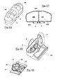
- a dispenser device according an eight embodiment of the present invention is shown in Figures 24-27.
- the dispenser device of the eight embodiment differs from the dispenser device of the first embodiment for the possibility of delivering more products. Therefore the dispenser device of this eight embodiment comprises two cartridges 48 containing different products to deliver (Figure 24), or alternately a single cartridge 480 provided with two chambers 481 containing two different products to deliver (Figure 27).
- Said dispenser device comprises a body similar to the body 1 and provided with two mouth 9 one for each cartridge 48 or for each chamber 481 and a dispenser unit similar to the dispenser unit 3 provided with two lower valves 17 and two upper valves 25 for the mouths 9 and with a single spoon shape plate 20.
- the chambers 481 are provided with plugs 5 with closing member 482 which are pushed inside the chambers 481 by engaging with the mouths 9.
- the meaning of the dispenser device of this eight embodiment is similar to the meaning of the dispenser device of the first embodiment unless, in this case, two quantity of different products contained inside the two cartridges 48 are delivered.
- the feature of delivery more products by using two cartridges and a dispenser unit with two upper valves and two lower valves which belonging to this eight embodiment, which is substantially represented as a variant of the first embodiment, can be applied to all the preceding embodiments.
- FIGS 28 and 29 a new type of body 110 for the dispenser device according to invention is shown.
- the body 110 is different from the bodies of the aforementioned embodiments because it comprises a conveyor 111 for the water flow 19.
- This conveyor 111 is advantageous above all in the case of the water flow inside the toilet bowl 200 occurs in tangential to its internal walls.
Landscapes
- Health & Medical Sciences (AREA)
- Public Health (AREA)
- Epidemiology (AREA)
- Life Sciences & Earth Sciences (AREA)
- Engineering & Computer Science (AREA)
- Hydrology & Water Resources (AREA)
- Water Supply & Treatment (AREA)
- Devices For Dispensing Beverages (AREA)
- Sanitary Device For Flush Toilet (AREA)
Abstract
Description
- The invention refers to an automatic dispenser device for liquids or gels in toilet bowls.
- It is known that toilet bowls are cleaned and deodorized by using products in solid, gel or liquid form. Such products are placed in appropriate containers arranged in the flushing cistern in a way to be hung from the rim of the bowl. Also these containers are arranged in order to be exposed to the flow of the flushing water.
- At each water flow such products release into the water their active principles, such detergents, disinfectant and perfuming agents, and diffuse fragrances into the surrounding environment.
- Actually the liquid or gel containers are arranged with the output mouth facing downward and the dispensation of the product occurs by simple drop. Such containers are not provided with a closure device for the output mouth which assures the control of the outflow of the product in a way independent of the duration of the water flow.
- In fact, in this way inconstant and non-controllable outflows of the products occur from the output mouth during each water flow.
- In view of the art described, it is an object of the present invention to provide an automatic dispenser device for liquids or gels in toilet bowls which overcomes the aforementioned disadvantage.
- According to the present invention, such object is obtained by means of a dispenser device comprising at least one cartridge containing at least one liquid or gel and a support body for said cartridge which is provided with a bottom mouth for the outflow of liquid or gel, at least one first valve urged to close a first section of said mouth from the outside and control means responsive to each water flow to open said first valve, characterized by comprising at least one second valve for closing a second section of said mouth during each water flow, said at least one second valve being spaced from said at least one first valve so as define between said first and second sections of the mouth a quantity of said liquid or gel which is delivered by the dispenser device upon each water flow, there being provided valve connecting means for causing said at least one second valve to open said second section of the mouth when said at least one first valve is closed and to close said second section of the mouth when at least one first valve is open.
- Thanks of the present invention is possible to provide a dispenser device for liquids or gels of the automatic type because its operation occurs by means of a water flow used for cleaning the toilet bowl. Also the quantity of the liquid or gel to deliver is determined by the volume intercepted in the mouth between the two valves.
- The device can be made so as to allow the single or simultaneous delivery of several products; in such case the dispenser device comprises several cartridges and double valves units in measure equal to the cartridges being used.
- Moreover for making uniform the delivery outflow while maintaining for the entire time of use of the device the atmospheric pressure inside the air bubble of the cartridge in the cases of use of the type with additional hole.
- The features and the advantages of the present invention will be made evident by the following detailed description of its particular embodiments, illustrated as not limiting examples in the annexed drawings, wherein:
- Figures 1 and 2 show two types of cartridges of the automatic dispenser device according to invention;
- Figures 3 and 4 are perspective views of a body belonging to the dispenser device according to invention;
- Figure 5 shows a dispenser device unit belonging to the dispenser device according to a first embodiment of the invention;
- Figure 6 is a vertical section central view of the dispenser device according to the first embodiment of the invention before the fastening to a toilet bowl;
- Figure 7 is a vertical section central view of the dispenser device according to the first embodiment of the invention which is fastened to the toilet bowl;
- Figure 8 is a vertical section central view of the dispenser device according to the first embodiment of the invention at rest;
- Figure 9 is a view similar to that in Figure 8 but with the dispenser device in working phase;
- Figure 10 is a vertical section lateral view of the dispenser device according to the first embodiment of the invention at rest;
- Figure 11 is a view similar to that in Figure 8 but with the dispenser device in working phase;
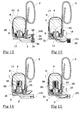
- Figure 12 is a vertical section central view of the dispenser device according to a second embodiment of the invention at rest;
- Figure 13 is a view similar to that in Figure 8 but with the dispenser device in working phase;
- Figure 14 is a vertical section central view of the dispenser device according to a third embodiment of the invention at rest;
- Figure 15 is a view similar to that in Figure 8 but with the dispenser device in working phase;
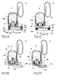
- Figure 16 is a vertical section central view of the dispenser device according to a fourth embodiment of the invention at rest;
- Figure 17 is a view similar to that in Figure 8 but with the dispenser device in working phase;
- Figure 18 is a vertical section central view of the dispenser device according to a fifth embodiment of the invention at rest;
- Figure 19 is a view similar to that in Figure 8 but with the dispenser device in working phase;
- Figure 20 is a vertical section central view of the dispenser device according to a sixth embodiment of the invention at rest;
- Figure 21 is a view similar to that in Figure 8 but with the dispenser device in working phase;
- Figure 22 is a vertical section central view of the dispenser device according to a seventh embodiment of the invention at rest;
- Figure 23 is a view similar to that in Figure 8 but with the dispenser device in working phase;
- Figures 24-26 show perspective views of elements belonging to a dispenser device according to an eight embodiment of the invention;
- Figure 27 shows an alternative embodiment of the cartridge in Figure 24;
- Figure 28 is another type of a body belonging to dispenser device according to invention;
- Figure 29 is a vertical section central view of a dispenser device comprising the body in Figure 28.
-
- A dispenser device according to the invention comprises a cartridge 4 (Figure 1) containing a product, liquid or gel, to deliver inside a toilet bowl. The cartridge can comprise a
hole 12 in the upper part (Figure 2) for putting into communication an air bubble 13 (Figure 7) formed inside thecartridge 4 with the outside in order to assure the atmospheric pressure inside thecartridge 4. Thecartridge 4 is provided in the bottom with aplug 5. When the dispenser device is sold, thehole 12 is closed by suitable means, for example by an adhesive label or by a removable plug. - The dispenser device comprises a support body 1 (Figures 3 and 4) on which the
cartridge 4 should be inserted. Thebody 1 is provided with anadditional hook 2 adapted for the fastening to a rim of the toilet bowl and with anelement 101 for spacing it from the wall of the toilet bowl. - The dispenser device comprises a unit 3 (Figure 5) according to a first embodiment of the invention which should be inserted in the
body 1. Theunit 3 is coupled with thebody 1 by rotatably coupling ofends 21 of theunit 3 insuitable housings 22 in thebody 1. Theunit 3 comprisesleaf springs 14 operating by means ofprojections 15 on thestriker plates 16 of thebody 1, anupper valve 25 adapted to be inserted in themouth 9 of thebody 1 and alower valve 17 adapted for closing theoutput section 18 of themouth 9; thevalves tang 26. Thedispenser device unit 3 comprises also ahole 27 placed on aspoon shape plate 20 next thevalve 17. - The operation of inserting of the
cartridge 4 in thebody 1 provides the cutting of aclosing diaphragm 555 of theplug 5 by means ofteeth 6 belonging to amouth 9 of thebody 1 which is provided with aninput section 29 and theoutput section 18; in this way, while thediaphragm 555 floats in theproduct 8, theproduct 8 contained in thecartridge 4 can go out from thecartridge 4 through themouth 9 to deliver it into the toilet bowl. The dispenser device so obtained can be fastened to therim 100 of thetoilet bowl 200 by means of thehook 2, as shown in Figure 7. - At rest (Figures 8 and 10) the
dispenser device unit 3, for effect of theleaf springs 14, keeps themouth 9 closed by means of thelower valve 17 that intercepts theoutput section 18 of themouth 9. - The arrival on the dispenser device of the water flow (indicated in Figures 9 and 11 with an arrow 19), which is employed for cleaning the toilet bowl, determines the working phase of the dispenser device. In fact the
water flow 19 generates a thrust on the spoon-shape plate 20 of theunit 3; the thrust causes a rotation of thedispenser device unit 3 around theends 21 placed in thehousing 22 of thebody 1. The stop of the rotation is defined by the contact of the ends 23 (opposite to the ends 21) with theprojections 24 of theelement 101 belonging to thebody 1. In this position theleaf springs 14 are additionally loaded. Thelower valve 17, by detaching itself from theoutflow section 18 of themouth 9, opens thesame mouth 9 thus allowing the output of a part of theproduct 8 into the spoon-shape plate 20; the part of theproduct 8 is diluted by the water flow. - The
upper valve 25, which is integral with thelower valve 17 and located upstream of it, by resulting immersed in the product inside thecartridge 4, facilities the dragging of the part of the product towards themouth 9. - At the end of the stroke the
upper valve 25, by placing itself inside themouth 9 and because of the viscosity of theproduct 8, interrupts the output of theproduct 8 from thecartridge 4. Therefore only a certain quantity or a dose of theproduct 8 can outflow from thecartridge 4. - The
dispenser device unit 3 also provides a dose of theproduct 8 contained in thecartridge 4 at each water flow; this dose does not depend on the time period wherein thewater flow 19 is present inside thetoilet bowl 200 but it depends on the distance between theinput 18 andoutput 29 section of saidmouth 9 and also on the size of themouth 9, that is on the quantity of theproduct 8 intercepted in themouth 9 between thevalves - When the
water flow 19 stops theleaf springs 14 loaded by the water flow provide to the returning action of thedispenser device unit 3 that, by returning in the rest position, restores the closing of thelower valve 17 on theoutput section 18 of themouth 9 and the opening of theupper valve 25 which closed themouth 9. This allows the air entrapped inside themouth 9 after the outflow of theproduct 8 to go up into theair bubble 13 and theproduct 8 to flow into themouth 9 in order to predispose the dispenser device for newly dispensing. - The
hole 27 of the spoon-shape plate 20 allows that the water accumulated during the working phase outflows through. - A dispenser device according a second embodiment of the present invention is shown in Figures 12 and 13. The dispenser device of the second embodiment differs from the dispenser device of the first embodiment for the introduction of at least one
contrast spring 32 in the place of the leaf springs 14. This at least onecontrast spring 32 is arranged in asuitable cavity 34 formed in theelement 101 of thebody 1 and it is engaged withpins 35 of theelement 101 and withpins 330 of theend part 33 of the spoon-shape plate 20 of theunit 3. As theleaf springs 14, thespring 32 operates for closing thevalve 17 on the output section of themouth 9 after each water flow. Thespring 32 therefore is further loaded when the water flow acts on theunit 3 and thevalve 17 is opened for the outflow of the product 8 (Figure 13) while thespring 32 acts on thevalve 17 for closing it in absence of the water flow (Figure 12). - A dispenser device according a third embodiment of the present invention is shown in Figures 14 and 15. The dispenser device of the third embodiment differs from the dispenser device of the first embodiment for the introduction of a
traction spring 36 in the place of theleaf springs 14 and of asupport 37 integral with thebody 1 and arranged inside thecartridge 4. Thesupport 37 is provided withopenings 38 for the passage of theproduct 8 through them. Thespring 36 is hinged with the upper part of thesupport 37 and with thevalve 25 of thedispenser device unit 3. As theleaf springs 14, thespring 36 operates for closing thevalve 17 on the output section of themouth 9 after each water flow. Thespring 36 therefore extends when the water flow acts on theunit 3 and thevalve 17 is opened for the outflow of the product 8 (Figure 15) while it acts on thevalve 17 for closing it by retraction in absence of the water flow (Figure 14). - A dispenser device according a fourth embodiment of the present invention is shown in Figures 16 and 17. The dispenser device of the fourth embodiment differs from the dispenser device of the first embodiment for a new type of
dispenser device unit 39; the last is not hinged rotatably with thebody 1, as theunit 3 of the preceding embodiments, but is hinged with at least twosprings 40 arranged inlower projections 42 of thebody 1 and engaged withpins 420 thereof and withpins 410 of theunit 39. Theseprojections 42 are formed respectively in theelement 104 and in theend 41 of the lower part of thebody 1 which is opposite to theelement 104. Thedispenser device unit 39 is provided with a the spoon-shape plate 43. Thesprings 40 operate for closing thevalve 170 on the output section of themouth 9 after each water flow. Thesprings 40 therefore are loaded when thewater flow 19 acts on theunit 39 and a lower valve 170 (which is similar to thevalve 17 and has the same function) is opened for the outflow of a certain quantity of the product 8 (Figure 17) while an upper valve 250 (which is similar to thevalve 25 and has the same function) closes themouth 9. Thesprings 40, which are loaded by thewater flow 19, act on thelower valve 170 for closing it in absence of the water flow (Figure 16). - A dispenser device according a fifth embodiment of the present invention is shown in Figures 18 and 19. The dispenser device of the fifth embodiment differs from the dispenser device of the first embodiment for the introduction of an
upper valve 46 in the place of thevalve 25. Thisvalve 46 is connected with thevalve 17 in a non-rigid way, in fact thevalves flexible cord 47. Theupper valve 46 is made up of a half cap shape element having a specific weight lower than theproduct 8 to deliver; in this way theupper valve 46 floats in theproduct 8 inside the cartridge 4 (Figure 18). Therefore when thelower valve 17 is opened for the outflow of the product 8 (Figure 19) theupper valve 46 covers an optimal vertical movement for the transfer operation of theproduct 8 from thecartridge 4 to themouth 9. - A dispenser device according a sixth embodiment of the present invention is shown in Figures 20 and 21. The dispenser device of the sixth embodiment differs from the dispenser device of the first embodiment for the introduction of an
upper valve 55 in the place of thevalve 25 and for the introduction of amouth 56 different with respect to themouth 9. In fact theinput section 156 of themouth 56 is shaped in a such way that thevalve 55 can carry out a mechanical closure of themouth 56 in the working phase. Thevalve 55 is coupled with thevalve 17 by means of aprojection 54 of thedispenser device unit 3 in the central part of thelower valve 17. When thelower valve 17 is opened for the outflow of theproduct 8 from theoutput section 256 of the mouth 56 (Figure 21), theupper valve 55 closes hermetically themouth 56 while at rest theleaf springs 14 allow thevalve 17 to close thelower section 256 of themouth 56 for preventing the outflow of the product 8 (Figure 20). - A dispenser device according a seventh embodiment of the present invention is shown in Figures 22 and 23. The dispenser device of the seventh embodiment differs from the dispenser device of the first embodiment for the introduction of an different type of a
mouth 62 and of adispenser device unit 60 always movable between the rest and working phases by means of thewater flow 19. Theunit dispenser device 60 is provided with a vertical projection 61 (which is transversal to thespoon shape plate 59 of the unit 60) acting on a ball 65. Themouth 62 is provided whit upperhorizontal projections 63 on theinput section 162 and lowerhorizontal projections 64 on theoutput section 262. Theprojections product 8 through themouth 62 and are adapted for coupling whit the ball 65 on which theprojection 61 acts; the ball 65 acts as a shutter for the input and output section of themouth 62 . Therefore the coupling of the upperhorizontal projections 63 with the ball 65 allows the ball 65 itself to act as a valve for the closure of thecartridge 4 at rest phase (Figure 22) while the coupling of the lowerhorizontal projections 64 with the ball 65 allows the ball 65 itself to act as a valve for the closure of thecartridge 4 in the working phase (Figure 23). The quantity of theproduct 8 which outflows from thecartridge 4 is defined by the distance between the input and output sections of themouth 62 and by the change of position of the ball 65 between the rest phase and the working phase. However, in this case, a part of theproduct 8 is delivered by thecartridge 4 in the passage between the rest phase and the working phase for emptying themouth 9 and said part of theproduct 8 can outflows from themouth 62 at the successive rest phase when theprojection 61 of the control means 60 acts (by means of elastic means as leaf spring which are not shown in Figures 22 and 23 but which are similar to theleaf spring 14 in Figure 5) on the ball 65 to open thesection 262 and to close thesection 162. The ball 65, which has a weight higher than theproduct 8, goes down for gravity during the working phase in presence of thewater flow 19. Thespoon shape plate 59 of theunit 60 is not provided with a hole because the quantity of theproduct 8 which is delivered at rest remains on thespoon shape plate 59 for carrying out a perfuming action between a water flow and one following. - A dispenser device according an eight embodiment of the present invention is shown in Figures 24-27. The dispenser device of the eight embodiment differs from the dispenser device of the first embodiment for the possibility of delivering more products. Therefore the dispenser device of this eight embodiment comprises two
cartridges 48 containing different products to deliver (Figure 24), or alternately asingle cartridge 480 provided with twochambers 481 containing two different products to deliver (Figure 27). Said dispenser device comprises a body similar to thebody 1 and provided with twomouth 9 one for eachcartridge 48 or for eachchamber 481 and a dispenser unit similar to thedispenser unit 3 provided with twolower valves 17 and twoupper valves 25 for themouths 9 and with a singlespoon shape plate 20. Also thechambers 481 are provided withplugs 5 with closingmember 482 which are pushed inside thechambers 481 by engaging with themouths 9. The meaning of the dispenser device of this eight embodiment is similar to the meaning of the dispenser device of the first embodiment unless, in this case, two quantity of different products contained inside the twocartridges 48 are delivered. The feature of delivery more products by using two cartridges and a dispenser unit with two upper valves and two lower valves which belonging to this eight embodiment, which is substantially represented as a variant of the first embodiment, can be applied to all the preceding embodiments. - In Figures 28 and 29 a new type of
body 110 for the dispenser device according to invention is shown. Thebody 110 is different from the bodies of the aforementioned embodiments because it comprises aconveyor 111 for thewater flow 19. Thisconveyor 111 is advantageous above all in the case of the water flow inside thetoilet bowl 200 occurs in tangential to its internal walls.
Claims (24)
- Dispenser device comprising at least one cartridge (4, 48, 480) containing at least one liquid or gel (8) and a support body (1, 110) for said cartridge (4, 48, 480) which is provided with a bottom mouth (9, 56, 62) for the outflow of liquid or gel (8), at least one first valve (17, 170, 65) urged to close a first section (18, 256, 162) of said mouth (9, 56, 62) from the outside and control means (3, 39, 60) responsive to each water flow (19) to open said first valve (17, 170, 65), characterized by comprising at least one second valve (25, 250, 55, 65) for closing a second section (29, 156, 262) of said mouth (9, 56, 62) during each water flow (19), said at least one second valve (25, 250, 55, 65) being spaced from said at least one first valve (17, 170, 65) so as define between said first (18, 256, 162) and second (29, 156, 262) sections of the mouth (9, 56, 62) a quantity of said liquid or gel (8) which is delivered by the dispenser device upon each water flow (19), there being provided valve connecting means (26, 47, 54) for causing said at least one second valve (25, 250, 55, 65) to open said second section (29, 156, 262) of the mouth (9, 56, 62) when said at least one first valve (17, 170, 65) is closed and to close said second section (29, 156, 262) of the mouth (9, 56, 62) when at least one first valve (17, 170, 65) is open.
- Dispenser device according to claim 1, characterized in that said second section (29, 156) is the input section of the mouth (9, 56) and the first section (18, 256) is the output section of the mouth (9, 56), said at least one second valve (25, 250, 55) being placed inside said at least one cartridge (4, 48, 480) and said at least one first valve (17, 170) being integral with said control means (3, 39).
- Dispenser device according to claim 2, characterized in that said control means (3) are rotatably connected with the dispenser device.
- Dispenser device according to claim 3, characterized in that said control means (3) comprises a spoon shape plate (20) adapted to collect the quantity of liquid or gel (8) delivered by the at least one cartridge (4, 48, 480).
- Dispenser device according to claim 3, characterized in that said control means (3) comprises elastic means (14, 32, 36) which are loaded by the water flow (19) and which act on the said at least one first valve (17) for placing it to close said mouth (9, 56) when the water flow (19) stops.
- Dispenser device according to claim 5, characterized in that said elastic means (14) are leaf springs in contrast with a fixed part (16) of the dispenser device.
- Dispenser device according to claim 5, characterized in that said elastic means (32) is a contrast spring in contrast with a fixed part (101) of the dispenser device.
- Dispenser device according to claim 5, characterized by comprising a support (37) integral with the dispenser and arranged inside the at least one cartridge (4, 48, 480) in a position over the mouth (9), said at least one second valve (25) being integral with at least one first valve (17) and said elastic means (36) being a traction spring (36) hinged to the support (37) and the at least one second valve (25).
- Dispenser device according to anyone of the claims from 2 to 8, characterized in that said second valve (25, 46) closes said mouth (9) placing itself inside said mouth (9), said liquid or gel (8) being of the viscous type.
- Dispenser device according to claim 9, characterized in that said second valve (25) is integral with the at least one first valve (17).
- Dispenser device according to claim 9, characterized in that said second valve (46) has a specific weight lower than the liquid or gel of the cartridge (4) for floating inside it, the second valve (46) being connected with at the least one first valve (17) by means of a flexible cord (47).
- Dispenser device according to anyone of the claims from 1 to 8, characterized in that said second valve (55) is integral with said at least one first valve (17) and closes said mouth (56) by placing itself in contact with the second section (156) of the mouth (56).
- Dispenser device according to claim 2, characterized in that said control means (39) is engaged with the dispenser device by means of elastic means (40) arranged in lower projections (42) of the dispenser device, said at least one second valve (250) being integral with said at least one first valve (170), said elastic means (40) being loaded by the water flow (19) and acting on the said at least one first valve (170) for placing it to close said mouth (9) when the water flow (19) stops.
- Dispenser device according to claim 13, characterized in that said second valve (250) closes said mouth (9) placing itself inside said mouth, said liquid or gel being of the viscous type.
- Dispenser device according to claim 14, characterized in that said control means (39) comprises a spoon shape plate (43) adapted to collect the quantity of liquid or gel (8) delivered by the at least one cartridge (4, 48, 480).
- Dispenser device according to claim 4 or 15, characterized in that said spoon shape plate (20, 43) is provided with a hole (27, 270) for the outflow of the water accumulated during the water flow (19).
- Dispenser device according to claim 4 or 15, characterized in that said support body (110) comprises a conveyor (111) of the water flow (19) into said spoon shape plate (20, 43).
- Dispenser device according to claim 1, characterized in that said first section (162) is the input section of the mouth (62) and the second section (262) is the output section of the mouth (62), said first (162) and second (262) sections of the mouth (62) being provided with projections (63, 64) for coupling with a shutter (65) acting as first valve in absence of the water flow (19) and as second valve in presence of the water flow (19).
- Dispenser device according to claim 18, characterized in that said control means (60) comprises elastic means loaded by the water flow (19) and acting on the shutter (65) for placing it to close said first section (162) of the mouth (62) when the water flow (19) stops in order to allow the delivery of said quantity of liquid or gel (8) contained in the mouth (62).
- Dispenser device according to claim 19, characterized in that said control means (60) comprises a projection (61) adapted for acting on the shutter (65) for closing said first section (162) of the mouth (62) in absence of the water flow (19), this control means (60) allowing the shutter to go down for closing the second section (262) in presence of the water flow (19).
- Dispenser device according to claim 20, characterized in that said control means (60) are rotatably connected with the dispenser device and comprise a spoon shape plate (59) for collect the quantity of liquid or gel delivered by the cartridge (4, 48, 480).
- Dispenser device according to claim 1, characterized in that said at least one cartridge (480) is a single cartridge provided with two chambers (481) containing two liquids or gels which are delivered, and by comprising two mouths (9) each one for each chamber (481) of said cartridge (480).
- Dispenser device according to claim 1, characterized by comprising two cartridges (48) containing two liquids or gels which are delivered, and by comprising two mouths (9) each one for each cartridges (481).
- Dispenser device according to claim 1, characterized in that said cartridge comprises a hole (12) formed in the upper part thereof, said hole (12) putting into communication an air bubble (13) formed inside the cartridge with the outside.
Applications Claiming Priority (2)
| Application Number | Priority Date | Filing Date | Title |
|---|---|---|---|
| ITMI20022155 ITMI20022155A1 (en) | 2002-10-11 | 2002-10-11 | AUTOMATIC DISPENSER WITH PREDOSED QUANTITY OF LIQUIDS OR GEL, FOR THE DISSEMINATION OF DISINFECTANT CLEANSING PRODUCTS OR PERFUME ESSENCES, IN THE SANITARY SERVICES. |
| ITMI20022155 | 2002-10-11 |
Publications (2)
| Publication Number | Publication Date |
|---|---|
| EP1408164A2 true EP1408164A2 (en) | 2004-04-14 |
| EP1408164A3 EP1408164A3 (en) | 2005-01-26 |
Family
ID=32012175
Family Applications (1)
| Application Number | Title | Priority Date | Filing Date |
|---|---|---|---|
| EP02080447A Withdrawn EP1408164A3 (en) | 2002-10-11 | 2002-12-19 | Automatic dispenser device for liquids or gels in toilet bowls |
Country Status (2)
| Country | Link |
|---|---|
| EP (1) | EP1408164A3 (en) |
| IT (1) | ITMI20022155A1 (en) |
Cited By (3)
| Publication number | Priority date | Publication date | Assignee | Title |
|---|---|---|---|---|
| WO2015082748A1 (en) * | 2013-12-05 | 2015-06-11 | Zobele España, S.A. | Device for supplying a product inside a toilet bowl |
| WO2018224818A1 (en) * | 2017-06-06 | 2018-12-13 | Reckitt Benckiser (Brands) Limited | In-the-bowl dispensing device |
| CN111764480A (en) * | 2020-07-09 | 2020-10-13 | 李期仞 | External quantitative liquid discharging device |
Citations (5)
| Publication number | Priority date | Publication date | Assignee | Title |
|---|---|---|---|---|
| US3946448A (en) * | 1973-11-02 | 1976-03-30 | Mekopharma Dr. Becker & Cie. K.G. | Apparatus for disinfection and chemical purification of toilet bowls |
| WO2001004428A1 (en) * | 1999-07-14 | 2001-01-18 | Deoflor S.P.A. | Device for delivering an active substance in liquid phase inside a toilet bowl |
| DE10025972A1 (en) * | 2000-05-25 | 2001-12-06 | Henkel Kgaa | Cleaning fluid dispenser for lavatory bowls has integral chamber with flushing water intake and outlet, and dispenser opening closed by closure element with seal |
| WO2002040787A1 (en) * | 2000-11-17 | 2002-05-23 | Henkel Kommanditgesellschaft Auf Aktien | Distributing device for distributing fluids containing active ingredients |
| DE10205299A1 (en) * | 2001-03-01 | 2002-09-12 | Alpla Werke | Dispenser, to deliver a dosed volume of liquid into a toilet cistern, has a labyrinth passage through two catch basins to deliver a dose each time the toilet is flushed |
-
2002
- 2002-10-11 IT ITMI20022155 patent/ITMI20022155A1/en unknown
- 2002-12-19 EP EP02080447A patent/EP1408164A3/en not_active Withdrawn
Patent Citations (5)
| Publication number | Priority date | Publication date | Assignee | Title |
|---|---|---|---|---|
| US3946448A (en) * | 1973-11-02 | 1976-03-30 | Mekopharma Dr. Becker & Cie. K.G. | Apparatus for disinfection and chemical purification of toilet bowls |
| WO2001004428A1 (en) * | 1999-07-14 | 2001-01-18 | Deoflor S.P.A. | Device for delivering an active substance in liquid phase inside a toilet bowl |
| DE10025972A1 (en) * | 2000-05-25 | 2001-12-06 | Henkel Kgaa | Cleaning fluid dispenser for lavatory bowls has integral chamber with flushing water intake and outlet, and dispenser opening closed by closure element with seal |
| WO2002040787A1 (en) * | 2000-11-17 | 2002-05-23 | Henkel Kommanditgesellschaft Auf Aktien | Distributing device for distributing fluids containing active ingredients |
| DE10205299A1 (en) * | 2001-03-01 | 2002-09-12 | Alpla Werke | Dispenser, to deliver a dosed volume of liquid into a toilet cistern, has a labyrinth passage through two catch basins to deliver a dose each time the toilet is flushed |
Cited By (8)
| Publication number | Priority date | Publication date | Assignee | Title |
|---|---|---|---|---|
| WO2015082748A1 (en) * | 2013-12-05 | 2015-06-11 | Zobele España, S.A. | Device for supplying a product inside a toilet bowl |
| ES2540304A1 (en) * | 2013-12-05 | 2015-07-09 | Zobele España, S.A. | Device for the supply of a product inside the toilet bowl (Machine-translation by Google Translate, not legally binding) |
| EP3078781A4 (en) * | 2013-12-05 | 2017-08-02 | Zobele España, S.A. | Device for supplying a product inside a toilet bowl |
| US10214888B2 (en) | 2013-12-05 | 2019-02-26 | Zobelle Espana, S.A. | Device for supplying a product inside a toilet bowl |
| WO2018224818A1 (en) * | 2017-06-06 | 2018-12-13 | Reckitt Benckiser (Brands) Limited | In-the-bowl dispensing device |
| US11124954B2 (en) | 2017-06-06 | 2021-09-21 | Reckitt Benckiser (Brands) Limited | In-the-bowl dispensing device |
| EP3635186B1 (en) * | 2017-06-06 | 2023-11-01 | Reckitt Benckiser (Brands) Limited | In-the-bowl dispensing device |
| CN111764480A (en) * | 2020-07-09 | 2020-10-13 | 李期仞 | External quantitative liquid discharging device |
Also Published As
| Publication number | Publication date |
|---|---|
| ITMI20022155A1 (en) | 2004-04-12 |
| EP1408164A3 (en) | 2005-01-26 |
Similar Documents
| Publication | Publication Date | Title |
|---|---|---|
| EP0182671B1 (en) | Discharge assembly | |
| US4018363A (en) | Soap dispenser | |
| EP0207715B1 (en) | Vented discharge assembly for liquid soap dispenser | |
| AU646461B2 (en) | Dishwasher detergent dispenser | |
| EP1911385A2 (en) | Fluid soap dispenser and fluid soap bottle associated to the dispenser | |
| EP2390009A1 (en) | Metering arrangement for dispensing metered quantities of liquid from a deformable container | |
| JPH08511436A (en) | Improved liquid dispenser | |
| US3778849A (en) | Automatic dispensing apparatus | |
| GB1579617A (en) | Device for dispensing powdered material | |
| US4491988A (en) | In-tank toilet bowl cleaner dispenser | |
| CA1291599C (en) | Automatic toilet bowl cleaner dispenser | |
| EP1408164A2 (en) | Automatic dispenser device for liquids or gels in toilet bowls | |
| US4507811A (en) | Toilet bowl dispenser | |
| EP3234269A1 (en) | Post-flush dispenser for a hygiene composition | |
| AU2011101604A4 (en) | A dispenser unit | |
| US20060053538A1 (en) | Toilet rim block holder | |
| EP1386040B1 (en) | Down-stroke dispenser | |
| US20040078879A1 (en) | In-tank dispenser with flexible supported valve head | |
| US4962549A (en) | In-tank dispensing device for dosing a toilet bowl | |
| GB2139661A (en) | Float-actuated pump adding disinfectant to a W.C. cistern | |
| US4451941A (en) | Toilet bowl sanitizer dispenser | |
| WO2003104086A2 (en) | Dispensing device for cleaning agents | |
| CA1263341A (en) | Automatic dispensers for metering liquid soluble or suspendible materials | |
| EP1426505A3 (en) | Universal dispenser of sanitizing liquid for containers of water or the like, particularly flushing cisterns for toilets | |
| WO2005120320A2 (en) | Dispensing system and method of use |
Legal Events
| Date | Code | Title | Description |
|---|---|---|---|
| PUAI | Public reference made under article 153(3) epc to a published international application that has entered the european phase |
Free format text: ORIGINAL CODE: 0009012 |
|
| AK | Designated contracting states |
Kind code of ref document: A2 Designated state(s): AT BE BG CH CY CZ DE DK EE ES FI FR GB GR IE IT LI LU MC NL PT SE SI SK TR |
|
| AX | Request for extension of the european patent |
Extension state: AL LT LV MK RO |
|
| PUAL | Search report despatched |
Free format text: ORIGINAL CODE: 0009013 |
|
| AK | Designated contracting states |
Kind code of ref document: A3 Designated state(s): AT BE BG CH CY CZ DE DK EE ES FI FR GB GR IE IT LI LU MC NL PT SE SI SK TR |
|
| AX | Request for extension of the european patent |
Extension state: AL LT LV MK RO |
|
| AKX | Designation fees paid | ||
| REG | Reference to a national code |
Ref country code: DE Ref legal event code: 8566 |
|
| STAA | Information on the status of an ep patent application or granted ep patent |
Free format text: STATUS: THE APPLICATION IS DEEMED TO BE WITHDRAWN |
|
| 18D | Application deemed to be withdrawn |
Effective date: 20050727 |