EP1408144A2 - Weft tension device of a loom - Google Patents
Weft tension device of a loom Download PDFInfo
- Publication number
- EP1408144A2 EP1408144A2 EP03019991A EP03019991A EP1408144A2 EP 1408144 A2 EP1408144 A2 EP 1408144A2 EP 03019991 A EP03019991 A EP 03019991A EP 03019991 A EP03019991 A EP 03019991A EP 1408144 A2 EP1408144 A2 EP 1408144A2
- Authority
- EP
- European Patent Office
- Prior art keywords
- weft
- inducing pipeline
- reed
- tension device
- pipeline
- Prior art date
- Legal status (The legal status is an assumption and is not a legal conclusion. Google has not performed a legal analysis and makes no representation as to the accuracy of the status listed.)
- Withdrawn
Links
Images





Classifications
-
- D—TEXTILES; PAPER
- D03—WEAVING
- D03D—WOVEN FABRICS; METHODS OF WEAVING; LOOMS
- D03D47/00—Looms in which bulk supply of weft does not pass through shed, e.g. shuttleless looms, gripper shuttle looms, dummy shuttle looms
- D03D47/28—Looms in which bulk supply of weft does not pass through shed, e.g. shuttleless looms, gripper shuttle looms, dummy shuttle looms wherein the weft itself is projected into the shed
- D03D47/30—Looms in which bulk supply of weft does not pass through shed, e.g. shuttleless looms, gripper shuttle looms, dummy shuttle looms wherein the weft itself is projected into the shed by gas jet
- D03D47/3066—Control or handling of the weft at or after arrival
- D03D47/308—Stretching or holding the weft
Definitions
- a weft tension device to have, in addition to a function to capture a non-weft-supply side weft end so as to apply a tension to the weft, a function to discharge the non-weft-supply side weft end.
- the weft end on the non-supply side of the inserted weft is displaced within the weft capturing pipe by the air jetted from the stretch nozzle.
- the captured weft end is thereafter drawn out of the weft capturing pipe by the air jetted from the excluding nozzle from the side of the weft capturing pipe toward the side of the non-capturing pipe.
- An object of the present inventions lies in readily removing a captured weft end without using a weft exclusion nozzle.
- the weft tension device comprises: a stretch nozzle disposed on a non-weft-supply side so as to jet a fluid toward a weft running path: a penetrated weft inducing pipeline having a weft introducing end opposite to a fluid port of the stretch nozzle so as to introduce the weft end by the fluid jetting operation of the stretch nozzle; and blocking means for blocking the non-weft-introducing end side of the weft inducing pipeline during at least a part of a period from the introduction of the weft end to the introduction of the weft end of the following pick into the weft inducing pipeline.
- the stretch nozzle performs a fluid jet motion performed when the blocking of the weft inducing pipeline by at least the blocking means.
- the fluid jet motion from the stretch nozzle for holding the weft is started at least before or after the weft reaches the non-weft-supply side (non-weft-insert side).
- the non-weft-inducing end side of the weft inducing pipeline is open, so that the ejected fluid passes through the weft inducing pipeline from the weft introducing end side to the non-weft-introducing end side. Thereby, the weft end is drawn into the weft inducing pipeline and captured.
- the non-weft-inducing end side of the weft inducing pipeline is blocked, and when the fluid is jetted from the stretch nozzle, the weft inducing pipeline is filled with the fluid, which overflows out of the pipeline, and by this overflowed fluid, the weft end captured inside the weft inducing pipeline is discharged from the weft inducing end.
- the weft end which has been captured can be easily discharged from the weft inducing pipeline at every weft insert pick. Also, since there is no need to provide the weft tension device without a discharge function with a valve for a jet nozzle for discharging the fluid except adding blocking means, the structure is simple and the device is inexpensive.
- the fluid jet motion performed when the weft inducing pipeline is blocked may be done to meet a timing for discharging the weft from the weft inducing pipeline. It is also possible to utilize the residual pressure of the jetting during the period of tension applying instead of jetting for discharge.
- the weft inducing pipeline is connected to the reed so as to move together with the reed
- the blocking means can include a shield body which can move together with the reed and, as well as a drive mechanism for moving the shield body and disposed in the loom.
- the blocking means may block the non-weft-inducing end side during at least a part of the period other than the period for applying the tension to the weft.
- the fluid jet port of the stretch nozzle and the weft introducing end of the weft inducing pipeline may confront each other with the weft running path interposed.
- the fluid jet port of the stretch nozzle and the weft introducing end of the weft inducing pipeline may oppose each other with a weft guide groove of a dent portion of the reed interposed or may oppose with the weft running path of the non-supply side rather than the reed interposed.
- the blocking means can be provided with an elastic body to be elastically deformed when the non-weft-introducing end side is blocked.
- the elastic body is elastically deformed to block the non-weft-introducing end side, so that adhesion between the non-weft-introducing end side of the weft inducing pipeline and the blocking means becomes high, and there is no risk that the air within the weft inducing pipeline might leak, and the discharging force of the weft end becomes stronger.
- a weft tension device 10 is applied to an air jet loom for inserting a weft 12 which is run within a weft guide groove 16 of a reed 14 by a main nozzle and a plurality of sub nozzles.
- the reed 14 has a plurality of dents 18 extending in the upward and downward at intervals in the cloth width direction, and the guide groove 16 is directed toward the cloth fell.
- the weft tension device 10 is disposed on a non-weft-supply side so as to capture a weft end 12a on the non-weft-supply side (non-weft-insert side) in order to apply tension to the inserted weft 12 and thereafter to discharge the weft end 12a.
- the weft tension device 10 comprises: a stretch nozzle 20 disposed on the non-weft-supply side so as to jet the compressed air toward the running path of the weft 12; the weft inducing pipeline 22 penetrated so as to introduce the weft end 12a by fluid jetting motion of the stretch nozzle 20; a shield body 24 for opening and closing the non-weft-introducing end side of the weft inducing pipeline 22; and an opening and closing valve 28 for supplying the compressed air of the compressed air source 26 to the stretch nozzle 20.
- the stretch nozzle 20 is disposed in a suitable member such as a lead sley so that the compressed air from a fluid jet port 30 can pass across a portion of the weft guide groove 16 and pass through between the dents 18 on the non-weft-supply side from the cloth side to the non-cloth side.
- the stretch nozzle 20 is moved together with the reed 14.
- the weft inducing pipeline 22 shaped like a pipe bent substantially like an L-letter, makes one end oppose to the fluid jet port 30 as a weft introducing end at the weft inlet port.
- the weft inducing pipeline 22 is also disposed in a suitable member such as a lead sley and connected to the reed 14 so as to move together with the reed 14.
- the shield body 24 is shaped like a shield plate supported on a frame 32 of the loom so as to block the other side (non-weft-introducing end) of the weft inducing pipeline 22 when the reed 14 is moved to the most backward position.
- the compressed air source 26 has a compressor, a tank for storing the compressed air, and a pressure regulation valve for supplying the compressed air from the tank to an opening and closing valve 28 by regulating the compressed air to a predetermined pressure.
- the opening and closing valve 28 is opened or closed at a predetermined timing by a control unit 34.
- the control unit 34 releases the opening and closing valve 28 in a period to apply tension to the weft 12 and in a period to discharge the weft ends 12a within the weft inducing pipeline 22 on the basis of a rotation angle signal from an encoder 38 which generates a signal representing a rotation angle of a main shaft 36.
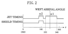
- the opening timing of the opening and closing valve 28 can be a period from 220° to 340° and a period before and after 180° in accordance with the rotation angle ⁇ of the main shaft 36, as shown in Fig. 2 as the air jet timing.
- the non-weft-introducing end side of the weft inducing pipeline 22 is, as shown in Fig. 2 as the shield timing, blocked substantially at the same time as the jet timing for discharging the weft end.
- the weft 12 at this time is applied tension and beaten when the main shaft 36 is at 0° (360°). Then, insertion of the next weft 12 is started.
- the trimmed selvedge length of the weft 12 inserted this time is longer than the reed sley stroke, it sometimes happens that the weft end 12a is not discharged from the weft inducing pipeline 22.
- the weft end 12a of the weft 12 inserted this time is discharged from the weft inducing pipeline 22 at the time of the next weft insertion and before the weft end 12a of the weft 12 that time is introduced into the weft inducing pipeline 22.
- the weft end 12a which has been captured can be readily discharged from the weft inducing pipeline 22 at each weft insert pick. Also, only blocking means including the shield body 24 is added to a weft tension device which has no discharging function so as to synchronize with the loom by utilizing the swinging motion of the reed 14, and since there is no need to have a fluid jet nozzle for discharge or a valve therefore, the structure is simple, and the device is inexpensive.
- the stretch nozzle 20 is disposed adjacent to the non-supply side of the reed 14 with the fluid nozzle directed upward so as to jet the air from the lower part toward the upper part, and is attached to a reed sley 44 by means of an L-shaped bracket 42.
- the bracket 42 also directs the weft guide groove 16 toward the cloth fell at a position in the weaving width direction of the weft guide groove 16 of the reed 14.
- a yarn sensor 46 is attached to the reed sley 44, to detect that the weft 12 is at a predetermined position of the non-supply side.
- the weft inducing pipeline 22 is attached to the upper part of the bracket 42 such that, in order to receive the air and the weft end 12a jetted upward from the weft inducing end (finally, the weft inlet port) side, the weft introducing end side opposes to the fluid jet port of the stretch nozzle 20.
- the shield body 24 is attached to a bracket 50 which supports a temple cover 48, so as to block the non-weft-introducing end side of the weft inducing pipeline 22 when the reed 14 moved to the most advanced position.
- the temple cover 48 is a publicly known one which is attached to the frame 32 of the loom by the bracket 50 so as to cover a temple 52 which maintains the weaving width.
- the jet timing from the stretch nozzle 20 is set at a period ⁇ 1 which includes a period for applying the tension to the weft 12 and an allowance, and at a period ⁇ 2 for discharging the weft end. It is also possible to set the period ⁇ 1 and the period ⁇ 2 not in sequence but individually.
- the jet timing can be, as shown in Fig. 4 as the jet timing, a period from 220° to 360° in accordance with the rotation angle ⁇ of the main shaft 36.
- the jet timing can be, as shown in Fig. 4 as the jet timing, a period from 220° to 360° in accordance with the rotation angle ⁇ of the main shaft 36.
- the weft introducing end side of the weft inducing pipeline 22 is, as shown in Fig. 4 as the shield timing, blocked substantially at the same time as the jet timing for discharging the weft end.
- the air is jetted from the stretch nozzle 20 while the reed 14 is advanced from the most backward position and the weft end 12a of the inserted weft 12 is reaching the vicinity of the non-supply side.
- the air from the stretch nozzle 20 passes the weft inducing pipeline 22.
- the weft end 12a of the weft 12 inserted this time is captured by the weft inducing pipeline 22. In this state, the tension is applied to the weft 12 at this time.
- the non-introducing end side of the weft inducing pipeline 22 is blocked by the shield body 24.
- the air is jetted from the stretch nozzle 20 until the weft 12 is beaten, the air is overflowed out of the weft inducing pipeline 22 like the weft tension device 10, the weft end 12a captured in the weft inducing pipeline 22 is discharged from the weft introducing end of the weft inducing pipeline 22 by the overflowing air.
- the weft end 12a of the weft 12 inserted this time is discharged from the weft inducing pipeline 22 before the next weft is inserted.
- the weft tension device 40 also enables to give an action and effect similar to that of the weft tension device 10.
- the weft tension device may have a blocking body for blocking the non-introducing end side of the weft inducing pipeline 22 when the reed 14 moved to the most backward position, and a blocking body for blocking the non-introducing end side of the weft inducing pipeline 22 when the reed 14 moved to the most advanced position.
- the jetting direction of the stretch nozzle 20 may be any directions, whether vertically or horizontally.
- the non-introducing end side of the weft inducing pipeline 22 is blocked with the beating motion of the reed 14, but it is possible to have the non-introducing end of the weft inducing pipeline 22 blocked by moving the shield body 24 forcibly by means of a specific drive mechanism with a drive source such as an actuator or with the main shaft as a drive source.
- a weft tension device 60 shown in Fig. 5 blocks the non-introducing end side of the weft inducing pipeline 22 by forcibly reciprocating the shield body 24 by a drive mechanism 62 within a plane orthogonal to the axis of the non-introducing end side of the weft inducing pipeline 22.
- the drive mechanism 62 has a drive source.
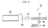
- a weft tension device 70 shown in Fig. 6 blocks the non-introducing end side of the weft inducing pipeline 22 by forcibly reciprocating the shield body 24 by a drive mechanism 72 in the axial direction of the non-introducing end side of the weft inducing pipeline 22.
- the drive mechanism 72 has a drive source.
- a weft tension device 80 shown in Fig. 7 blocks the non-introducing end side of the weft inducing pipeline 22 by forcibly swinging the shield body 24 to an opening position and a blocking position within a plane orthogonal to the non-introducing end side of the weft inducing pipeline 22.
- the drive mechanism 82 has a drive source.
- the drive mechanisms 62, 72 and 82 are reciprocated respectively at a predetermined timing in accordance with the rotational angles of the main shaft 36 by means of the control units 64, 74 and 84.
- the control units 64, 74 and 84 supply signals for moving the shield body 24 to the drive mechanisms 62, 72 and 82 respectively on the basis of the rotation angle signal from the encoder 38 for generating the signal representing the rotation angle of the main shaft 36.
- the timing for blocking the non-introducing end side of the weft inducing pipeline 22 may be a part of the period from when the non-supply side weft end 12a of the inserted weft 12 is introduced into the weft inducing pipeline 22 until the weft end 12a of the next pick is introduced into the weft inducing pipeline 22, as in case the reed 14 reached the vicinity of the most backward position or the most advanced position like the weft tension devices 10 and 40.
- the weft tension device 90 uses a shield body 96 which uses a cylindrical leaf spring 92 having a cross-section such as elliptical, circular or the like with a rubber sheet 94 mounted thereon.
- the shield body 96 is attached to the frame 32 of the loom so that, when the reed sley 44 is moved to the most backward position or the most advanced position, the non-introducing end side of the weft inducing pipeline 22 may be blocked with the rubber sheet 94.
- Fig. 8 shows the state when the reed sley 44 is moved to the most advanced position.
- the leaf spring 92 and the rubber sheet 94 are elastically deformable, so that, when the shield body 96 is pressed against the non-introducing end side of the weft inducing pipeline 22 by the movement of the reed sley 44, the shield body 96 is elastically deformed and blocks the non-introducing end side of the weft inducing pipeline 22 with the rubber sheet 94. Consequently, adhesion between the non-introducing end side of the weft inducing pipeline 22 and the shield body 96 is raised, and there is no fear for the air inside the weft inducing pipeline 22 to leak from the non-introducing end side, which raises the discharging force of the weft end 12a.
- the timing for blocking the non-introducing end side of the weft inducing pipeline 22 is set as a part of the period from when the non-supply side weft end 12a of the inserted weft 12 is introduced into the weft inducing pipeline 22 until the weft end 12a of the next pick is introduced into the weft inducing pipeline 22, but it may be the entire period except a period for applying the tension to the weft 12.
- the timing for blocking the non-introducing end side of the weft inducing pipeline 22 may be at least a part of the entire period except the period for applying the tension to the weft 12.
Landscapes
- Engineering & Computer Science (AREA)
- Textile Engineering (AREA)
- Looms (AREA)
Abstract
Description
Claims (9)
- A weft tension device of a loom comprising:wherein said stretch nozzle (20) performs fluid jet motion performed when the blocking of said weft inducing pipeline at least for a part of the period at least by said blocking means.a stretch nozzle (20) disposed on a non-weft-supply side to jet fluid toward a weft running path;a weft inducing pipeline (22) which is penetrated, said pipeline having a weft introducing end opposite to a fluid jet port of said stretch nozzle (20) to introduce weft end (12a) by fluid jetting operation of said stretch nozzle (20); andblocking means for blocking the non-weft-introducing end side of said weft inducing pipeline at least for a part of a period from when said weft end (12a) is introduced into said weft inducing pipeline (22) until the weft end (12a) of the next pick is introduced into said weft inducing pipeline (22);
- A weft tension device according to claim 1, wherein the fluid jet motion performed when blocking of said weft inducing pipeline (22) is performed in accordance with a timing to discharge the weft from said weft inducing pipeline (22).
- A weft tension device according to claim 1 or 2, wherein said weft inducing pipeline (22) is connected to a reed (14) so as to move together with said reed (14), and said blocking means includes a shield body (24,96) disposed in a loom so as to block said non-weft-induction end side when said reed (14) was moved at least to one of the most backward position and the most advanced position.
- A weft tension device according to claim 1 or 2, wherein said weft inducing pipeline (22) is connected to said reed (14) so as to move together with said reed (14), and said blocking means includes: a shield body connected to said reed (14) so as to move together with said read (14) so that said non-weft-introducing end side can be opened and closed; and a drive mechanism (62,72,82) for moving said shield body (24,96) and disposed in the loom.
- A weft tension device according to any one of claims 1 through 4, wherein said blocking means blocks said non-weft-introducing end side at least for a part of a period except the period for applying the tension to said weft (12).
- A weft tension device according to any one of claims 1 through 5, wherein said fluid jet port of said stretch nozzle (20) and said weft introducing end of said weft inducing pipeline (22) oppose to each other through a running path of said weft (12).
- A weft tension device according to claim 6, wherein said fluid jet port of said stretch nozzle (20) and said weft introducing end of said weft inducing pipeline (22) oppose to each other through said weft running path of the dent portion of said reed (14).
- A weft tension device according to claim 6, wherein the fluid jet port of said stretch nozzle and the weft introducing end of said weft inducing pipeline oppose to each other, through said weft running path on the non-weft-supply side rather than the reed.
- A weft tension device according to any one of claims 1 through 8, wherein said blocking means has an elastic body to be elastically deformed while said non-weft-introducing end side is blocked.
Applications Claiming Priority (2)
| Application Number | Priority Date | Filing Date | Title |
|---|---|---|---|
| JP2002297438 | 2002-10-10 | ||
| JP2002297438 | 2002-10-10 |
Publications (2)
| Publication Number | Publication Date |
|---|---|
| EP1408144A2 true EP1408144A2 (en) | 2004-04-14 |
| EP1408144A3 EP1408144A3 (en) | 2004-12-22 |
Family
ID=32025568
Family Applications (1)
| Application Number | Title | Priority Date | Filing Date |
|---|---|---|---|
| EP03019991A Withdrawn EP1408144A3 (en) | 2002-10-10 | 2003-09-03 | Weft tension device of a loom |
Country Status (1)
| Country | Link |
|---|---|
| EP (1) | EP1408144A3 (en) |
Cited By (1)
| Publication number | Priority date | Publication date | Assignee | Title |
|---|---|---|---|---|
| GB2545218A (en) * | 2015-12-09 | 2017-06-14 | Griffith Textile Mach Ltd | Improvements in or relating to weaving looms |
Family Cites Families (4)
| Publication number | Priority date | Publication date | Assignee | Title |
|---|---|---|---|---|
| BE1005230A3 (en) * | 1991-01-04 | 1993-06-01 | Picanol Nv | Device for seeking an impact on wire looms. |
| DE19810129B4 (en) * | 1998-03-09 | 2004-08-05 | Lindauer Dornier Gmbh | Weft stretching and detection device for jet weaving machines |
| JP2000154441A (en) * | 1998-11-17 | 2000-06-06 | Toyota Autom Loom Works Ltd | Weft yarn tensioning device of jet loom |
| JP2000170057A (en) * | 1998-12-09 | 2000-06-20 | Toyota Autom Loom Works Ltd | Device for giving tension to filling yarn in jet loom |
-
2003
- 2003-09-03 EP EP03019991A patent/EP1408144A3/en not_active Withdrawn
Cited By (1)
| Publication number | Priority date | Publication date | Assignee | Title |
|---|---|---|---|---|
| GB2545218A (en) * | 2015-12-09 | 2017-06-14 | Griffith Textile Mach Ltd | Improvements in or relating to weaving looms |
Also Published As
| Publication number | Publication date |
|---|---|
| EP1408144A3 (en) | 2004-12-22 |
Similar Documents
| Publication | Publication Date | Title |
|---|---|---|
| EP2449158B1 (en) | Device and method for catching and stretching weft threads in weaving machines | |
| EP0493847B1 (en) | Device for the stretching of a weft thread in weaving machines | |
| JP6119715B2 (en) | Weft tension applying device for air jet loom | |
| US4570683A (en) | Yarn holding device | |
| CN110093707B (en) | Water jet device for water jet loom | |
| CN103221598B (en) | Gripper head for the insertion of weft threads on a gripper weaving machine | |
| EP1428918A3 (en) | Auxiliary nozzle for a weaving loom | |
| JP2005264416A5 (en) | ||
| JP2004150001A (en) | Weft tensioning device for loom | |
| US7066213B2 (en) | Catching and holding apparatus for the catching-side weft thread end in a weaving machine | |
| US4967803A (en) | Defective weft removal with unseparated weft lengths | |
| JP2014231649A (en) | Weft tension applying device in air jet loom | |
| US4729411A (en) | Air jet weaving machine | |
| EP1413659A1 (en) | Weft holding device in fluid jet loom | |
| EP0013821B1 (en) | Projectile launching and receiving apparatus for a pneumatic loom | |
| JPS6228446A (en) | Mistake yarn removing apparatus in jet loom | |
| US20050236062A1 (en) | Method for holding taut a weft thread and a loom for carrying out said method | |
| JP2530132B2 (en) | Bad yarn removing device for shuttleless loom | |
| JPH0431269Y2 (en) | ||
| JPH10280253A (en) | Weft yarn end capturer for water jet type loom | |
| CN101230515A (en) | Catching apparatus and method for a rapier weaving machine | |
| JP3446527B2 (en) | Weft processing equipment in jet looms | |
| JP2000119938A (en) | Water jet room | |
| JPH0466Y2 (en) | ||
| JP3551597B2 (en) | Vibrating ear control device in loom |
Legal Events
| Date | Code | Title | Description |
|---|---|---|---|
| PUAI | Public reference made under article 153(3) epc to a published international application that has entered the european phase |
Free format text: ORIGINAL CODE: 0009012 |
|
| AK | Designated contracting states |
Kind code of ref document: A2 Designated state(s): AT BE BG CH CY CZ DE DK EE ES FI FR GB GR HU IE IT LI LU MC NL PT RO SE SI SK TR |
|
| AX | Request for extension of the european patent |
Extension state: AL LT LV MK |
|
| PUAL | Search report despatched |
Free format text: ORIGINAL CODE: 0009013 |
|
| AK | Designated contracting states |
Kind code of ref document: A3 Designated state(s): AT BE BG CH CY CZ DE DK EE ES FI FR GB GR HU IE IT LI LU MC NL PT RO SE SI SK TR |
|
| AX | Request for extension of the european patent |
Extension state: AL LT LV MK |
|
| AKX | Designation fees paid | ||
| REG | Reference to a national code |
Ref country code: DE Ref legal event code: 8566 |
|
| STAA | Information on the status of an ep patent application or granted ep patent |
Free format text: STATUS: THE APPLICATION IS DEEMED TO BE WITHDRAWN |
|
| 18D | Application deemed to be withdrawn |
Effective date: 20050623 |