EP1407889A1 - Lubricating system including a lubricating structure - Google Patents
Lubricating system including a lubricating structure Download PDFInfo
- Publication number
- EP1407889A1 EP1407889A1 EP20030009062 EP03009062A EP1407889A1 EP 1407889 A1 EP1407889 A1 EP 1407889A1 EP 20030009062 EP20030009062 EP 20030009062 EP 03009062 A EP03009062 A EP 03009062A EP 1407889 A1 EP1407889 A1 EP 1407889A1
- Authority
- EP
- European Patent Office
- Prior art keywords
- lubricating
- carriage
- pad
- rod
- printing
- Prior art date
- Legal status (The legal status is an assumption and is not a legal conclusion. Google has not performed a legal analysis and makes no representation as to the accuracy of the status listed.)
- Granted
Links
- 230000001050 lubricating effect Effects 0.000 title claims abstract description 45
- 239000012530 fluid Substances 0.000 claims abstract description 8
- 238000007639 printing Methods 0.000 claims description 20
- 230000007246 mechanism Effects 0.000 claims description 10
- 238000000034 method Methods 0.000 claims description 4
- 239000000976 ink Substances 0.000 description 12
- 239000000356 contaminant Substances 0.000 description 5
- 239000000463 material Substances 0.000 description 4
- 230000004044 response Effects 0.000 description 4
- 230000009471 action Effects 0.000 description 2
- 239000003086 colorant Substances 0.000 description 2
- 235000012489 doughnuts Nutrition 0.000 description 2
- 238000005516 engineering process Methods 0.000 description 2
- 239000000835 fiber Substances 0.000 description 2
- 238000007641 inkjet printing Methods 0.000 description 2
- 230000003993 interaction Effects 0.000 description 2
- 239000000314 lubricant Substances 0.000 description 2
- 239000010687 lubricating oil Substances 0.000 description 2
- 239000003921 oil Substances 0.000 description 2
- 230000003287 optical effect Effects 0.000 description 2
- 230000036316 preload Effects 0.000 description 2
- 230000035945 sensitivity Effects 0.000 description 2
- 239000004753 textile Substances 0.000 description 2
- 229920002799 BoPET Polymers 0.000 description 1
- 239000005041 Mylar™ Substances 0.000 description 1
- 230000002745 absorbent Effects 0.000 description 1
- 239000002250 absorbent Substances 0.000 description 1
- 230000006978 adaptation Effects 0.000 description 1
- 239000000443 aerosol Substances 0.000 description 1
- 238000004140 cleaning Methods 0.000 description 1
- 239000002131 composite material Substances 0.000 description 1
- 230000007547 defect Effects 0.000 description 1
- 239000000428 dust Substances 0.000 description 1
- 239000001041 dye based ink Substances 0.000 description 1
- 238000010304 firing Methods 0.000 description 1
- 230000002401 inhibitory effect Effects 0.000 description 1
- 238000007648 laser printing Methods 0.000 description 1
- 239000007788 liquid Substances 0.000 description 1
- 239000002184 metal Substances 0.000 description 1
- 230000005012 migration Effects 0.000 description 1
- 238000013508 migration Methods 0.000 description 1
- 239000012188 paraffin wax Substances 0.000 description 1
- 239000002245 particle Substances 0.000 description 1
- 239000013618 particulate matter Substances 0.000 description 1
- 230000002093 peripheral effect Effects 0.000 description 1
- 239000000049 pigment Substances 0.000 description 1
- 239000001042 pigment based ink Substances 0.000 description 1
- 239000004033 plastic Substances 0.000 description 1
- 230000008569 process Effects 0.000 description 1
- 238000004080 punching Methods 0.000 description 1
- 239000000126 substance Substances 0.000 description 1
- 229920001169 thermoplastic Polymers 0.000 description 1
- 239000004416 thermosoftening plastic Substances 0.000 description 1
- 230000000007 visual effect Effects 0.000 description 1
- 239000001993 wax Substances 0.000 description 1
Images

Classifications
-
- B—PERFORMING OPERATIONS; TRANSPORTING
- B41—PRINTING; LINING MACHINES; TYPEWRITERS; STAMPS
- B41J—TYPEWRITERS; SELECTIVE PRINTING MECHANISMS, i.e. MECHANISMS PRINTING OTHERWISE THAN FROM A FORME; CORRECTION OF TYPOGRAPHICAL ERRORS
- B41J29/00—Details of, or accessories for, typewriters or selective printing mechanisms not otherwise provided for
- B41J29/17—Cleaning arrangements
Definitions
- Inkjet printing mechanisms such as printers, may use print cartridges which shoot drops of liquid colorant, referred to generally herein as "ink," onto a print medium, such as a page of paper.
- a print cartridge may have a printhead formed with very small nozzles through which the ink drops are fired.
- the printhead, or a printhead carriage supporting the printhead may be propelled back and forth across the page along a printhead carriage rod, shooting drops of ink in a desired pattern as it moves.
- the particular ink ejection mechanism within the printhead may be implemented in a variety of different ways, such as by piezo-electric or thermal printhead technology.
- the carriage rod may become fouled with contaminants such as dust, ink aerosol particles, and print media particulate matter such as paper fibers.
- contaminants may interfere with smooth motion of the printhead carriage, thereby reducing print quality.
- the contaminants may cause friction between the printhead carriage and the carriage rod, thereby increasing strain on printer motors.
- the contaminants may also damage the printhead carriage or the carriage rod, thereby reducing the working life of the printer.
- a lubricating pad in the shape of a closed loop or a "doughnut", may be frictionally fit around a circumference of the carriage rod.
- An inner diameter of the closed pad may be made smaller than the outer diameter of the carriage rod to ensure intimate contact of the closed pad with the sliding surface of the rod so that lubricating fluid is imparted thereto.
- the lubricating pad may lubricate and clean around the entire circumference of the carriage rod as the closed pad is moved therealong.
- the tight fitting closed pad may impart a large drag to the printhead carriage thereby straining printer motors and inhibiting accurate movement of the printhead carriage.
- a lubricating system includes a flexible, nominally planar lubricating structure including first and second end regions and a central region positioned therebetween.
- the lubricating structure is impregnated with a lubricating fluid and is adapted for securement to a printhead carriage only at said first and second end regions.
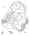
- FIG. 1 illustrates one embodiment of a printing mechanism, here shown as an inkjet printer 20, which may be used for printing of business reports, correspondence, desktop publishing, and the like, in an industrial, office, home or other environment.
- a printing mechanism here shown as an inkjet printer 20
- a variety of printing mechanisms is commercially available, which frequently use inkjet or laser printing technology or the like.
- Some of the printing mechanisms that may use embodiments of the lubricating device include plotters, portable printing units, copiers, video printers, and facsimile machines, to name a few. For convenience the concepts of the lubricating device are illustrated in the environment of an inkjet printer 20.
- the inkjet printer 20 may include a chassis 22, such as a metal frame, surrounded by a housing or casing enclosure 24, typically manufactured of a polymeric material such as plastic. Sheets of print media are fed through a printzone 25 by a print media handling system 26.
- the print media may be any type of suitable sheet material, such as paper, card-stock, transparencies, mylar, and the like, but for convenience, the illustrated embodiment is described using paper as the print medium.
- the print media handling system 26 typically has a feed tray 28 for storing sheets of paper before printing. A series of motor-driven paper drive rollers (not shown) may be used to move the print media from tray 28 into the printzone 25 for printing.
- the media handling system 26 may include a series of adjustment mechanisms for accommodating different sizes of print media, including letter, legal, A-4, envelopes, etc., such as a sliding length and width adjustment levers 32 and 33 for the input tray, and a sliding length adjustment lever 34 for the output tray.
- the printer 20 also has a printer controller, illustrated schematically as a microprocessor 35, that receives instructions from a host device, typically a computer, such as a personal computer (not shown), communicatively coupled to printer 20 via electrical, optical, or RF methods and the like. Indeed, many of the printer controller functions may be performed by the host computer, by the electronics on board the printer, or by interactions therebetween. As used herein, the term “printer controller 35" encompasses these functions, whether performed by the host computer, the printer, an intermediary device therebetween, or by a combined interaction of such elements. The printer controller 35 may also operate in response to user inputs provided through a key pad (not shown) located on the exterior of the casing 24. A monitor coupled to the host computer may be used to display visual information to an operator, such as the printer status or the user interface of a particular program being run on the host computer.
- a printer controller illustrated schematically as a microprocessor 35, that receives instructions from a host device, typically a computer, such as a personal computer (
- a carriage guide rod 36 also called a carriage support member, a polished shaft or a support bar, may be mounted to chassis 22 to define a scanning direction or axis 38.
- the carriage rod 36 slideably supports a reciprocating printhead carriage 40, which may be an inkjet printhead itself or which may support at least one inkjet printhead such as a replaceable inkjet printhead, which travels back and forth across the printzone 25.
- a lubricating device 42 may be positioned on printhead carriage 40, and will be discussed in greater detail below with respect to embodiments of the present invention. In other embodiments the lubricating device may be positioned on a servicing sled or otherwise separate from the printhead carriage 40 but generally will be positioned adjacent the carriage rod.
- the illustrated exemplary printhead carriage 40 carries two inkjet print cartridges 44 and 46 over the printzone 25 for printing, though any number or type of cartridges may be used.
- Each of the printheads may selectively eject droplets of ink onto a sheet of print media (not shown) in response to firing signals received from the controller 35, such as black ink from cartridge 44, and/or at least one colored ink from cartridge 46.
- any type of inks and/or colors may be used in cartridges 44 and 46, such as dye-based inks, pigment based inks, thermoplastic, wax or paraffin based inks, as well as hybrid or composite inks having both dye and pigment characteristics.
- the illustrated cartridges 44 and 46 may each include reservoirs for storing a supply of ink.
- Any carriage propulsion system may be used to drive the printhead carriage 40, including a position feedback system, which communicates carriage position signals to the controller 35.
- a carriage drive gear (not shown) and a DC motor assembly 52 may be coupled to drive an endless belt secured to the carriage 40, with the motor operating in response to control signals received from the printer controller 35.
- an optical encoder reader (not shown) may be mounted to carriage 40 to read an encoder strip extending along the path of carriage travel.
- FIG. 2 shows a detailed perspective view of lubricating structure 42, which functions as a lubricating pad, a cleaning device, and a friction reducing means.
- Pad 42 may comprise a flexible, nominally planar member or expanse including first and second end regions also called tabs, 54 and 56, respectively, and a central region 58, also called a span, positioned therebetween.
- the pad may be generally rectangular in shape and define a length 60, a width 62 and a thickness 64.
- Central region 58 may be more particularly defined as extending centrally along approximately 80% of length 60, whereas end regions 54 and 56 each generally extend along the 10%, respectively, of each end of length 60.
- length 60 may be approximately 22 millimeters (mm)
- width 62 may be approximately 10mm
- thickness 64 may be approximately 1.5mm.
- the thickness 64 may be at least 10% of the length 60 and the width may be at least 50% of the length.
- any length, width, and thickness dimensions may be utilized as is desired for a particular application.
- End regions 54 and 56 as shown each have a width slightly smaller than width 62 of central region 58 so as to be secured within corresponding slots of printhead carriage 40, as will be discussed below.
- end regions 54 and 56 may include other securement means such as angled surfaces, clips, snaps, apertures or the like, as may be useful for particular applications.
- pad 42 may be manufactured with any peripheral shape, such as a disk, an oblong, a triangle, etc., that defines a planar expanse. Pad 42 is not a closed or an endless loop, meaning that end regions 54 and 56 are positioned opposite one another across planar span 58.
- Pad 42 may be manufactured of an absorbent textile material, such as needlefelt. Needlefelt is a non-woven textile produced by mechanically, chemically or thermally interlocking layers of fibers, filaments or yarns, in a process called needle punching on a needle loom machine. Pad 42 may be impregnated with a lubricating fluid, such as a low-viscosity lubricating oil. The oil may be drawn out of the pad through capillary action and deposited onto the sliding surface of the carriage rod 36 as necessary. Pad 42 may be impregnated with a sufficient amount of lubricating fluid such that pad 42 will lubricate the carriage rod throughout the life of the printer. In other embodiments, pad 42 may be periodically cleaned, lubricated and/or replaced throughout the life of the printer.
- a lubricating fluid such as a low-viscosity lubricating oil. The oil may be drawn out of the pad through capillary action and deposited onto the sliding surface of the carriage rod 36 as necessary. Pad 42 may be
- FIG. 3 illustrates pad 42 secured within printhead carriage 40.
- Printhead carriage 40 includes first and second slots, also called securement devices 66 and 68, adapted for receiving therein first and second end regions 54 and 56, respectively, of pad 42.
- first and second end regions 54 and 56 of pad 42 are secured within slots 66 and 68 by friction due to the tight fit of the pads within the slots 54 and 56.
- securement devices 66 and 68 may comprise angled surfaces, clips, snaps, apertures or the like, as may be useful for particular applications, and manufactured so as to mate with the securement device positioned in end regions 54 and 56 of pad 42.
- an aperture or open region 70 Positioned between securement device 66 and 68 on carriage 40 is an aperture or open region 70 that allows access to, and deflection of, central region 58 of pad 42.
- pad 42 is "simply supported” by the printhead carriage 40, i.e., supported only at end regions 54 and 56 of the pad, much like a beam, such that central region 58 is generally unconstrained by the printhead carriage.
- central region 58 is exposed for contact with carriage rod 36 and is free to deflect in response to contact with the carriage rod.
- pad 42 is tautly secured within printhead carriage 40 and is not in contact with carriage rod 36 and, therefore, is in its nominally flat, planar orientation.
- Printhead carriage 40 is shown having an open region 71 such that the printhead carriage does not completely surround a carriage rod or support member upon which the printhead carriage may be mounted.
- FIGS. 4 and 5 illustrate printhead carriage 40 mounted on carriage rod 36 such that slots 66 and 68 are positioned generally on opposite sides of the carriage rod 36.
- printhead carriage 40 may be mounted on carriage rod 36 by mounting means (not shown) separate from pad 42, wherein the mounting means ensures proper movement of the printhead carriage along carriage rod 36.
- the printhead carriage 40 may include more than one pad 42, such as a first pad secured on one side of the printhead carriage 40 and a second pad secured on an opposite side of the printhead carriage 40.
- the carriage rod 36 is lubricated and/or cleaned on both sides of the printhead carriage 40 as the carriage moves along the carriage rod 36.
- Carriage rod 36 may comprise a generally circular cross sectional shape but any shaped cross section of carriage rod 36 may be utilized.
- carriage rod 36 may comprise a square, an oval or a rectangular cross-shaped shaft.
- Rod 36 may also comprise an inverted "U" shaped cross-sectional shape, wherein the rod is supported along its length by a bar received within the lower recess of the carriage rod. Support of carriage rod 36 entirely along its length may reduce vibrational and positional errors of the printhead carriage, and a printhead supported thereon, during printing as the printhead carriage is moved along the carriage rod.
- slots 66 and 68 of printhead carriage 40 may be positioned slightly lower, in a direction 72, than a plane 74 (shown in end view as a line in FIG. 5) defined by a topmost portion of a pad contacting surface 76 of carriage rod 36, such that a rod contacting surface 78 of pad 42 contacts pad contacting surface 76 of the carriage rod, as will be described subsequently in greater detail.
- slots 66 and 68 are aligned with a plane 75 (shown in end view as a line in FIG. 5) that defines a lowermost portion of pad contacting surface 76, as will be described in more detail below.
- This offset of slots 66 and 68 with the topmost portion of rod 36 is chosen so as to force the pad 42 to deflect slightly from its nominally flat orientation when the pad contacts the carriage rod 36, thereby providing a controlled pre-load, i.e., a predetermined contact force between the pad contacting surface 76 of the carriage rod 36 and the rod contacting surface 78 of nominally planar pad 42.
- the controlled pre-load ensures that the lubricated pad 42 is pressed against the pad contacting surface 76 of the carriage rod 36 with enough force and surface area so as to impart a desired amount of oil to the carriage rod 36 without significantly increasing drag between the printhead carriage 40 and the carriage rod 36.
- rod contacting surface 78 of central region 58 of pad 42 deflects upwardly approximately 1.5mm, a dimension similar to the thickness 64 of the pad, i.e., a deflection distance approximately 1 times the thickness of the pad 42.
- the amount of deflection 73 (shown in FIG. 5) of pad 42 may be measured from the peak of the curved portion of central region 58 during deflection, shown here as plane 74, to plane 75 defined by the pad in its nominally planar orientation.
- Pad 42 generally is manufactured of a material, and mounted on printhead carriage 40, such that central region 58 is adapted to deflect a distance 73 in a range of approximately 0.1 to 4.0 times the pad's thickness 64, and more particularly, in a range of approximately 0.5 times to 1.5 times the pad's thickness 64.
- the pad's thickness 64 is 1.5mm and the pad 42 is adapted to deflect a distance 73 in a range of approximately 0.75mm to 2.25mm from its nominally flat orientation.
- the pad 42 may be pre-loaded to deflect to a lesser or to a larger degree, and in a direction other than upwardly, such as, for example, downwardly if mounted below a support rod or to the side if mounted on the side of a support rod, as may be desired for a particular application.
- pad 42 In addition to applying lubricating oil to working surface 76 of the carriage rod 36, pad 42 physically wipes the pad contacting surface 76 of rod 36 so as to remove contaminants therefrom. Pad 42, therefore, lubricates and cleans carriage rod 36, thereby reducing frictional drag on the carriage rod and increasing the life of the printer.
- pad contacting surface 76 of the carriage rod Applicants generally mean the portion of the outer surface of the carriage rod used to support the printhead carriage 40.
- the pad contacting surface 76 of carriage rod 36 comprises approximately one fifth of the circumference of the generally cylindrically shaped carriage rod, extending upwardly and around the top surface of carriage rod 36, approximately from line 80 to line 82 (both lines shown in end view in FIG. 5).
- the pad contacting surface of the carriage rod 36 may comprise any portion less than 100% of the outer periphery of the carriage rod, as for example, within a range of 0 to 50% of the outer periphery or perimeter of the carriage rod 36.
- Pad 42 generally does not contact the entire outer periphery of carriage rod 36 but only contacts the carriage rod in a portion of the periphery, i.e., rod contacting surface 78 of the pad 42 only contacts rod 36 along pad contacting surface 76 of the rod 36.
- pad contacting surface 76 of rod 36 and rod contacting surface 78 of pad 42 are contiguous with one another such that the entire pad contacting surface of the rod is cleaned and lubricated while producing a reduced amount of friction on the rod when compared to the friction produced by prior art closed pads which entirely surround and frictionally engage a carriage rod.
- planar pad 42 only contacts a portion of the entire periphery of the rod, the rod may be supported along its length, such as along a lower or a side surface of the rod 36 by a cross bar 84, thereby reducing vibration of the rod 36 and the printhead carriage 40 as it moves along the rod.
- the nominally planar lubricating pad 42 provides many benefits.
- the pad 42 limits migration of lubricants from the pad during use because it utilizes capillary action to dispense the lubricant to the carriage rod 36 during use.
- Contact of the pad 42 with only the forward most portion, or the pad contacting surface 76, of the carriage rod reduces the printhead carriage drag's sensitivity to pad geometry, thereby increasing consistency of operation between similarly manufactured printers.
- slight variations in the inner diameter of closed pads of the prior art may result in inconsistent drag forces, whereas slight variations in the length of the planar pad 42 shown may be compensated for when the pad is secured within slots 66 and 68 of the printhead carriage 40.
- the pad 42 lubricates and cleans the pad contacting surface 76 of the carriage rod 36 in a single motion.
- the planar pad geometry allows the carriage rod 36 to be supported completely or periodically along its length, thereby allowing different mounting methods that may reduce carriage rod vibrations so as to improve positional accuracy and overall print quality.
Landscapes
- Ink Jet (AREA)
- Character Spaces And Line Spaces In Printers (AREA)
Abstract
Description
- Inkjet printing mechanisms, such as printers, may use print cartridges which shoot drops of liquid colorant, referred to generally herein as "ink," onto a print medium, such as a page of paper. Each print cartridge may have a printhead formed with very small nozzles through which the ink drops are fired. To print an image, the printhead, or a printhead carriage supporting the printhead, may be propelled back and forth across the page along a printhead carriage rod, shooting drops of ink in a desired pattern as it moves. The particular ink ejection mechanism within the printhead may be implemented in a variety of different ways, such as by piezo-electric or thermal printhead technology.
- To enhance print quality, smooth motion of the printhead carriage along the carriage rod may be desired. However, during printing the carriage rod may become fouled with contaminants such as dust, ink aerosol particles, and print media particulate matter such as paper fibers. Such contaminants may interfere with smooth motion of the printhead carriage, thereby reducing print quality. The contaminants may cause friction between the printhead carriage and the carriage rod, thereby increasing strain on printer motors. The contaminants may also damage the printhead carriage or the carriage rod, thereby reducing the working life of the printer.
- To clean and lubricate the carriage rod a lubricating pad, in the shape of a closed loop or a "doughnut", may be frictionally fit around a circumference of the carriage rod. An inner diameter of the closed pad may be made smaller than the outer diameter of the carriage rod to ensure intimate contact of the closed pad with the sliding surface of the rod so that lubricating fluid is imparted thereto. The lubricating pad may lubricate and clean around the entire circumference of the carriage rod as the closed pad is moved therealong. However, the tight fitting closed pad may impart a large drag to the printhead carriage thereby straining printer motors and inhibiting accurate movement of the printhead carriage. Moreover, slight variations in the diameters of different closed pads may result in different drag sensitivities of pads on different carriage rods, thereby reducing consistency in print quality between similarly produced printers. The doughnut shaped closed pad which completely encircles the carriage rod may require the carriage rod to be end-supported, which may facilitate vibration of the carriage rod during use. Such vibration may cause positional errors and print quality defects of the printhead.
- A lubricating system includes a flexible, nominally planar lubricating structure including first and second end regions and a central region positioned therebetween. The lubricating structure is impregnated with a lubricating fluid and is adapted for securement to a printhead carriage only at said first and second end regions.
-
- FIG. 1 is a perspective view of one embodiment of a printing mechanism including a lubricating system according to the present invention having a lubricating structure.
- FIG. 2 is a perspective view of one embodiment of the lubricating structure of FIG. 1 according to the present invention.
- FIG. 3 is a perspective view of the lubricating structure of FIG. 2 installed on a printhead carriage according to an embodiment of the present invention.
- FIG. 4 is a cross sectional perspective view of the lubricating structure of FIG. 2 and the printhead carriage of FIG. 3 mounted on a carriage rod according to an embodiment of the present invention.
- FIG. 5 is an end view of the lubricating structure, printhead carriage, and carriage rod of FIG. 4 according to an embodiment of the present invention.
-
- FIG. 1 illustrates one embodiment of a printing mechanism, here shown as an
inkjet printer 20, which may be used for printing of business reports, correspondence, desktop publishing, and the like, in an industrial, office, home or other environment. A variety of printing mechanisms is commercially available, which frequently use inkjet or laser printing technology or the like. Some of the printing mechanisms that may use embodiments of the lubricating device include plotters, portable printing units, copiers, video printers, and facsimile machines, to name a few. For convenience the concepts of the lubricating device are illustrated in the environment of aninkjet printer 20. - While it is apparent that the printer components may vary from model to model, the
inkjet printer 20 may include achassis 22, such as a metal frame, surrounded by a housing orcasing enclosure 24, typically manufactured of a polymeric material such as plastic. Sheets of print media are fed through aprintzone 25 by a printmedia handling system 26. The print media may be any type of suitable sheet material, such as paper, card-stock, transparencies, mylar, and the like, but for convenience, the illustrated embodiment is described using paper as the print medium. The printmedia handling system 26 typically has afeed tray 28 for storing sheets of paper before printing. A series of motor-driven paper drive rollers (not shown) may be used to move the print media fromtray 28 into theprintzone 25 for printing. After printing, the sheet lands onoutput tray portion 30. Themedia handling system 26 may include a series of adjustment mechanisms for accommodating different sizes of print media, including letter, legal, A-4, envelopes, etc., such as a sliding length and width adjustment levers 32 and 33 for the input tray, and a slidinglength adjustment lever 34 for the output tray. - The
printer 20 also has a printer controller, illustrated schematically as amicroprocessor 35, that receives instructions from a host device, typically a computer, such as a personal computer (not shown), communicatively coupled toprinter 20 via electrical, optical, or RF methods and the like. Indeed, many of the printer controller functions may be performed by the host computer, by the electronics on board the printer, or by interactions therebetween. As used herein, the term "printer controller 35" encompasses these functions, whether performed by the host computer, the printer, an intermediary device therebetween, or by a combined interaction of such elements. Theprinter controller 35 may also operate in response to user inputs provided through a key pad (not shown) located on the exterior of thecasing 24. A monitor coupled to the host computer may be used to display visual information to an operator, such as the printer status or the user interface of a particular program being run on the host computer. - Still referring to FIG. 1, a
carriage guide rod 36, also called a carriage support member, a polished shaft or a support bar, may be mounted tochassis 22 to define a scanning direction oraxis 38. Thecarriage rod 36 slideably supports areciprocating printhead carriage 40, which may be an inkjet printhead itself or which may support at least one inkjet printhead such as a replaceable inkjet printhead, which travels back and forth across theprintzone 25. Alubricating device 42 may be positioned onprinthead carriage 40, and will be discussed in greater detail below with respect to embodiments of the present invention. In other embodiments the lubricating device may be positioned on a servicing sled or otherwise separate from theprinthead carriage 40 but generally will be positioned adjacent the carriage rod. - The illustrated
exemplary printhead carriage 40 carries twoinkjet print cartridges printzone 25 for printing, though any number or type of cartridges may be used. Each of the printheads may selectively eject droplets of ink onto a sheet of print media (not shown) in response to firing signals received from thecontroller 35, such as black ink fromcartridge 44, and/or at least one colored ink fromcartridge 46. It is apparent that any type of inks and/or colors may be used incartridges cartridges - One suitable type of carriage support system is shown in U.S. Patent No. 5,366,305, assigned to Hewlett-Packard Company, the assignee of the subject application. Any carriage propulsion system may be used to drive the
printhead carriage 40, including a position feedback system, which communicates carriage position signals to thecontroller 35. For instance, a carriage drive gear (not shown) and aDC motor assembly 52 may be coupled to drive an endless belt secured to thecarriage 40, with the motor operating in response to control signals received from theprinter controller 35. To provide carriage positional feedback information toprinter controller 35, an optical encoder reader (not shown) may be mounted tocarriage 40 to read an encoder strip extending along the path of carriage travel. - FIG. 2 shows a detailed perspective view of
lubricating structure 42, which functions as a lubricating pad, a cleaning device, and a friction reducing means.Pad 42 may comprise a flexible, nominally planar member or expanse including first and second end regions also called tabs, 54 and 56, respectively, and acentral region 58, also called a span, positioned therebetween. The pad may be generally rectangular in shape and define alength 60, awidth 62 and athickness 64.Central region 58 may be more particularly defined as extending centrally along approximately 80% oflength 60, whereasend regions length 60. In the embodiment shownlength 60 may be approximately 22 millimeters (mm),width 62 may be approximately 10mm, andthickness 64 may be approximately 1.5mm. In many embodiments, thethickness 64 may be at least 10% of thelength 60 and the width may be at least 50% of the length. However, any length, width, and thickness dimensions may be utilized as is desired for a particular application.End regions width 62 ofcentral region 58 so as to be secured within corresponding slots ofprinthead carriage 40, as will be discussed below. In other embodiments,end regions pad 42 may be manufactured with any peripheral shape, such as a disk, an oblong, a triangle, etc., that defines a planar expanse.Pad 42 is not a closed or an endless loop, meaning thatend regions planar span 58. -
Pad 42 may be manufactured of an absorbent textile material, such as needlefelt. Needlefelt is a non-woven textile produced by mechanically, chemically or thermally interlocking layers of fibers, filaments or yarns, in a process called needle punching on a needle loom machine.Pad 42 may be impregnated with a lubricating fluid, such as a low-viscosity lubricating oil. The oil may be drawn out of the pad through capillary action and deposited onto the sliding surface of thecarriage rod 36 as necessary.Pad 42 may be impregnated with a sufficient amount of lubricating fluid such thatpad 42 will lubricate the carriage rod throughout the life of the printer. In other embodiments,pad 42 may be periodically cleaned, lubricated and/or replaced throughout the life of the printer. - FIG. 3 illustrates
pad 42 secured withinprinthead carriage 40.Printhead carriage 40 includes first and second slots, also calledsecurement devices second end regions pad 42. In the embodiment shown, first andsecond end regions pad 42 are secured withinslots slots securement devices end regions pad 42. Positioned betweensecurement device carriage 40 is an aperture oropen region 70 that allows access to, and deflection of,central region 58 ofpad 42. Accordingly,pad 42 is "simply supported" by theprinthead carriage 40, i.e., supported only atend regions central region 58 is generally unconstrained by the printhead carriage. In other words,central region 58 is exposed for contact withcarriage rod 36 and is free to deflect in response to contact with the carriage rod. In this figure,pad 42 is tautly secured withinprinthead carriage 40 and is not in contact withcarriage rod 36 and, therefore, is in its nominally flat, planar orientation.Printhead carriage 40 is shown having anopen region 71 such that the printhead carriage does not completely surround a carriage rod or support member upon which the printhead carriage may be mounted. - FIGS. 4 and 5 illustrate
printhead carriage 40 mounted oncarriage rod 36 such thatslots carriage rod 36. In one embodiment,printhead carriage 40 may be mounted oncarriage rod 36 by mounting means (not shown) separate frompad 42, wherein the mounting means ensures proper movement of the printhead carriage alongcarriage rod 36. In another embodiment, theprinthead carriage 40 may include more than onepad 42, such as a first pad secured on one side of theprinthead carriage 40 and a second pad secured on an opposite side of theprinthead carriage 40. In such an embodiment, thecarriage rod 36 is lubricated and/or cleaned on both sides of theprinthead carriage 40 as the carriage moves along thecarriage rod 36. -
Carriage rod 36 may comprise a generally circular cross sectional shape but any shaped cross section ofcarriage rod 36 may be utilized. For example,carriage rod 36 may comprise a square, an oval or a rectangular cross-shaped shaft.Rod 36 may also comprise an inverted "U" shaped cross-sectional shape, wherein the rod is supported along its length by a bar received within the lower recess of the carriage rod. Support ofcarriage rod 36 entirely along its length may reduce vibrational and positional errors of the printhead carriage, and a printhead supported thereon, during printing as the printhead carriage is moved along the carriage rod. - Still referring to FIGS. 4 and 5,
slots printhead carriage 40 may be positioned slightly lower, in adirection 72, than a plane 74 (shown in end view as a line in FIG. 5) defined by a topmost portion of apad contacting surface 76 ofcarriage rod 36, such that arod contacting surface 78 ofpad 42 contactspad contacting surface 76 of the carriage rod, as will be described subsequently in greater detail. In the embodiment shown,slots pad contacting surface 76, as will be described in more detail below. This offset ofslots rod 36 is chosen so as to force thepad 42 to deflect slightly from its nominally flat orientation when the pad contacts thecarriage rod 36, thereby providing a controlled pre-load, i.e., a predetermined contact force between thepad contacting surface 76 of thecarriage rod 36 and therod contacting surface 78 of nominallyplanar pad 42. The controlled pre-load ensures that the lubricatedpad 42 is pressed against thepad contacting surface 76 of thecarriage rod 36 with enough force and surface area so as to impart a desired amount of oil to thecarriage rod 36 without significantly increasing drag between theprinthead carriage 40 and thecarriage rod 36. In the embodiment shown,rod contacting surface 78 ofcentral region 58 ofpad 42 deflects upwardly approximately 1.5mm, a dimension similar to thethickness 64 of the pad, i.e., a deflection distance approximately 1 times the thickness of thepad 42. The amount of deflection 73 (shown in FIG. 5) ofpad 42 may be measured from the peak of the curved portion ofcentral region 58 during deflection, shown here asplane 74, to plane 75 defined by the pad in its nominally planar orientation.Pad 42 generally is manufactured of a material, and mounted onprinthead carriage 40, such thatcentral region 58 is adapted to deflect a distance 73 in a range of approximately 0.1 to 4.0 times the pad'sthickness 64, and more particularly, in a range of approximately 0.5 times to 1.5 times the pad'sthickness 64. In other words, in the embodiment shown, the pad'sthickness 64 is 1.5mm and thepad 42 is adapted to deflect a distance 73 in a range of approximately 0.75mm to 2.25mm from its nominally flat orientation. In other embodiments, thepad 42 may be pre-loaded to deflect to a lesser or to a larger degree, and in a direction other than upwardly, such as, for example, downwardly if mounted below a support rod or to the side if mounted on the side of a support rod, as may be desired for a particular application. - In addition to applying lubricating oil to working
surface 76 of thecarriage rod 36,pad 42 physically wipes thepad contacting surface 76 ofrod 36 so as to remove contaminants therefrom.Pad 42, therefore, lubricates and cleanscarriage rod 36, thereby reducing frictional drag on the carriage rod and increasing the life of the printer. By "pad contacting surface" 76 of the carriage rod, Applicants generally mean the portion of the outer surface of the carriage rod used to support theprinthead carriage 40. In the embodiment shown, thepad contacting surface 76 ofcarriage rod 36 comprises approximately one fifth of the circumference of the generally cylindrically shaped carriage rod, extending upwardly and around the top surface ofcarriage rod 36, approximately fromline 80 to line 82 (both lines shown in end view in FIG. 5). In other embodiments, the pad contacting surface of thecarriage rod 36 may comprise any portion less than 100% of the outer periphery of the carriage rod, as for example, within a range of 0 to 50% of the outer periphery or perimeter of thecarriage rod 36.Pad 42 generally does not contact the entire outer periphery ofcarriage rod 36 but only contacts the carriage rod in a portion of the periphery, i.e.,rod contacting surface 78 of thepad 42only contacts rod 36 alongpad contacting surface 76 of therod 36. In one embodiment,pad contacting surface 76 ofrod 36 androd contacting surface 78 ofpad 42 are contiguous with one another such that the entire pad contacting surface of the rod is cleaned and lubricated while producing a reduced amount of friction on the rod when compared to the friction produced by prior art closed pads which entirely surround and frictionally engage a carriage rod. Moreover, becauseplanar pad 42 only contacts a portion of the entire periphery of the rod, the rod may be supported along its length, such as along a lower or a side surface of therod 36 by across bar 84, thereby reducing vibration of therod 36 and theprinthead carriage 40 as it moves along the rod. - The nominally
planar lubricating pad 42 provides many benefits. Thepad 42 limits migration of lubricants from the pad during use because it utilizes capillary action to dispense the lubricant to thecarriage rod 36 during use. Contact of thepad 42 with only the forward most portion, or thepad contacting surface 76, of the carriage rod reduces the printhead carriage drag's sensitivity to pad geometry, thereby increasing consistency of operation between similarly manufactured printers. In other words, slight variations in the inner diameter of closed pads of the prior art may result in inconsistent drag forces, whereas slight variations in the length of theplanar pad 42 shown may be compensated for when the pad is secured withinslots printhead carriage 40. Thepad 42 lubricates and cleans thepad contacting surface 76 of thecarriage rod 36 in a single motion. Moreover, the planar pad geometry allows thecarriage rod 36 to be supported completely or periodically along its length, thereby allowing different mounting methods that may reduce carriage rod vibrations so as to improve positional accuracy and overall print quality. - Although a specific embodiment has been illustrated and described herein for purposes of description of the preferred embodiment, it will be appreciated by those of ordinary skill in the art that a wide variety of alternate and/or equivalent implementations calculated to achieve the same purposes may be substituted for the specific embodiment shown and described herein without departing from the scope of the present invention. Those with skill in the chemical, mechanical, electromechanical, electrical, and computer arts will readily appreciate that the present invention may be implemented in a very wide variety of embodiments. This application is intended to cover any adaptations or variations of the preferred embodiments discussed herein. Therefore, it is manifestly intended that this invention be limited only by the claims and the equivalents thereof.
Claims (10)
- A lubricating system (20), comprising:a flexible, nominally planar lubricating structure (42) including first (54) and second (56) end regions and a central region (58) positioned therebetween, the structure impregnated with a lubricating fluid and adapted for securement to a printhead carriage (40) only at said first and second end regions.
- A lubricating system (20) according to claim 1 wherein said structure (42) defines a generally rectangular expanse and wherein said first (54) and second (56) end regions are positioned opposite one another across said rectangular expanse.
- A lubricating system (20) according to claim 1 wherein said structure (42) is manufactured of needlefelt.
- A lubricating system (20) according to claim 1 wherein said structure (42) defines a width dimension (62), a length dimension (60) and a thickness dimension (64), wherein said thickness dimension (64) is at least 10% of said length dimension (60) and said width dimension (62) is at least 50% of said length dimension (60).
- A lubricating system (20) according to claim 1 wherein said structure (42) defines a length (60), and wherein said central region (58) extends along at most 80% of said length (60).
- A lubricating system (20) according to claim 1 further comprising a printhead carriage (40) mounted on a carriage rod (36), wherein said structure (42) is secured to said printhead carriage (40) only at said first (54) and second (56) end regions such that said central region (58) is flexed from its nominally planar orientation upon contact with said carriage rod (36).
- A printing mechanism (20), comprising:a printhead carriage (40) including first (66) and second (68) securement structures; anda lubricating pad (42) including a first end (54) secured to said first securement structure (66) and a second end (56) secured to said second securement structure (68) such that a central region (58) of said pad (42) does not contact said printhead carriage (40) and is adapted for deflection from a nominally planar orientation.
- A printing mechanism (20) according to claim 7 wherein said lubricating pad (42) defines a nominally planar expanse, and wherein said central region (58) is adapted to deflect a distance in a direction substantially orthogonal to the planar expanse in a range of approximately 0.5 times to 1.5 times the pad's thickness (64).
- A printing mechanism (20), comprising:printing means (46) for printing an image on a print medium;support means (36) for movably supporting said printing means (46) thereon; andfriction reducing means (42) simply supported by said printing means (46) such that only a portion of said friction reducing means contacts said support means (36) and is deflected by said support means (36) from a nominally flat orientation.
- A method of lubricating a support member (36), comprising:providing an elongate support member (36) adapted for movably mounting a printing structure (46) thereon;providing a nominally planar lubricating structure (42) simply supported at opposite ends (54, 56) thereof, said lubricating structure (42) impregnated with a lubricating fluid;placing said lubricating structure (42) in contact with said support member (36); andmoving said lubricating structure (42) along said elongate support member (36) to impart lubricating fluid thereto.
Applications Claiming Priority (2)
| Application Number | Priority Date | Filing Date | Title |
|---|---|---|---|
| US10/269,379 US6843549B2 (en) | 2002-10-10 | 2002-10-10 | Lubricating system including a lubricating structure |
| US269379 | 2002-10-10 |
Publications (2)
| Publication Number | Publication Date |
|---|---|
| EP1407889A1 true EP1407889A1 (en) | 2004-04-14 |
| EP1407889B1 EP1407889B1 (en) | 2006-08-09 |
Family
ID=32030384
Family Applications (1)
| Application Number | Title | Priority Date | Filing Date |
|---|---|---|---|
| EP03009062A Expired - Lifetime EP1407889B1 (en) | 2002-10-10 | 2003-04-17 | Lubricating system including a lubricating structure |
Country Status (4)
| Country | Link |
|---|---|
| US (1) | US6843549B2 (en) |
| EP (1) | EP1407889B1 (en) |
| JP (1) | JP2004130807A (en) |
| DE (1) | DE60307394D1 (en) |
Families Citing this family (6)
| Publication number | Priority date | Publication date | Assignee | Title |
|---|---|---|---|---|
| US7384125B2 (en) * | 2005-04-04 | 2008-06-10 | Hewlett-Packard Development Company, L.P. | Moving chassis |
| CN103189485A (en) * | 2010-10-25 | 2013-07-03 | Skf公司 | Apparatus for use in a system containing oil and/or lubricating fluid and method of forming the same |
| JP5857404B2 (en) * | 2010-12-20 | 2016-02-10 | セイコーエプソン株式会社 | Bearing structure and recording apparatus |
| TW201350353A (en) * | 2012-06-04 | 2013-12-16 | Hon Hai Prec Ind Co Ltd | Clean device and clean methord for printing ink |
| WO2021066795A1 (en) * | 2019-09-30 | 2021-04-08 | Hewlett-Packard Development Company, L.P. | Carriage beam arrangements including lubrication devices |
| US12157323B2 (en) | 2020-07-15 | 2024-12-03 | Hewlett-Packard Development Company, L.P. | Lubrication for carriage beam arrangements |
Citations (3)
| Publication number | Priority date | Publication date | Assignee | Title |
|---|---|---|---|---|
| US1536896A (en) * | 1924-07-30 | 1925-05-05 | Louis M Llorens | Typewriter-friction-rail lubricator |
| US3985404A (en) * | 1975-06-20 | 1976-10-12 | Xerox Corporation | Carriage support apparatus |
| JPH0531989A (en) * | 1991-07-31 | 1993-02-09 | Canon Inc | Carriage mover and recorder |
Family Cites Families (1)
| Publication number | Priority date | Publication date | Assignee | Title |
|---|---|---|---|---|
| JPS6222376Y2 (en) * | 1980-09-25 | 1987-06-06 |
-
2002
- 2002-10-10 US US10/269,379 patent/US6843549B2/en not_active Expired - Fee Related
-
2003
- 2003-04-17 DE DE60307394T patent/DE60307394D1/en not_active Expired - Lifetime
- 2003-04-17 EP EP03009062A patent/EP1407889B1/en not_active Expired - Lifetime
- 2003-10-07 JP JP2003348332A patent/JP2004130807A/en not_active Withdrawn
Patent Citations (3)
| Publication number | Priority date | Publication date | Assignee | Title |
|---|---|---|---|---|
| US1536896A (en) * | 1924-07-30 | 1925-05-05 | Louis M Llorens | Typewriter-friction-rail lubricator |
| US3985404A (en) * | 1975-06-20 | 1976-10-12 | Xerox Corporation | Carriage support apparatus |
| JPH0531989A (en) * | 1991-07-31 | 1993-02-09 | Canon Inc | Carriage mover and recorder |
Non-Patent Citations (1)
| Title |
|---|
| PATENT ABSTRACTS OF JAPAN vol. 017, no. 316 (M - 1430) 16 June 1993 (1993-06-16) * |
Also Published As
| Publication number | Publication date |
|---|---|
| JP2004130807A (en) | 2004-04-30 |
| EP1407889B1 (en) | 2006-08-09 |
| US20040080567A1 (en) | 2004-04-29 |
| US6843549B2 (en) | 2005-01-18 |
| DE60307394D1 (en) | 2006-09-21 |
Similar Documents
| Publication | Publication Date | Title |
|---|---|---|
| EP0913263B1 (en) | Hide-away wiper cleaner for inkjet printheads | |
| US6561619B1 (en) | Flipping wiper scraper system for inkjet printheads | |
| US6267466B1 (en) | Optical encoder system and method for use in printing devices | |
| JP3819223B2 (en) | Grooved tip wiper for inkjet printhead cleaning | |
| US6843549B2 (en) | Lubricating system including a lubricating structure | |
| JP4872336B2 (en) | Inkjet recording device | |
| JP4857764B2 (en) | Head cleaning device | |
| US6959978B2 (en) | Sensor cleaning apparatus for ink-jet printer | |
| GB2358613A (en) | Composite wiper blade for inkjet printhead cleaning wherein the blade is formed from at least two different elastomeric materials | |
| US6045212A (en) | Integral spring drive belt system for inkjet carriages | |
| JP4533109B2 (en) | Inkjet recording head, liquid storage container, and inkjet recording apparatus | |
| US6755504B2 (en) | Independent wiping of printhead | |
| US6659585B2 (en) | System and method for draining ink from ink receiving devices | |
| JP4725315B2 (en) | Scanning device | |
| JP4265991B2 (en) | Disk, encoder and image forming apparatus | |
| JP4556575B2 (en) | Carriage and recording apparatus | |
| JPH09131939A (en) | Micro-toothed carriage driving system for ink jet print head | |
| JP4911185B2 (en) | Cleaning member and recording apparatus to which cleaning member can be attached / detached | |
| US6896353B2 (en) | Inkjet printhead squeegee | |
| US6736481B2 (en) | System and method for cleaning ink ejection elements | |
| JP2007301798A (en) | Image recording device | |
| JP4888310B2 (en) | Platen for inkjet recording apparatus and inkjet recording apparatus | |
| JP4725332B2 (en) | Recording head positioning structure and recording apparatus | |
| JPH03290261A (en) | Wiping device for inkjet recording device | |
| JP2019147290A (en) | Ink jet printer |
Legal Events
| Date | Code | Title | Description |
|---|---|---|---|
| PUAI | Public reference made under article 153(3) epc to a published international application that has entered the european phase |
Free format text: ORIGINAL CODE: 0009012 |
|
| AK | Designated contracting states |
Kind code of ref document: A1 Designated state(s): AT BE BG CH CY CZ DE DK EE ES FI FR GB GR HU IE IT LI LU MC NL PT RO SE SI SK TR |
|
| AX | Request for extension of the european patent |
Extension state: AL LT LV MK |
|
| 17P | Request for examination filed |
Effective date: 20040513 |
|
| 17Q | First examination report despatched |
Effective date: 20040721 |
|
| AKX | Designation fees paid |
Designated state(s): DE FR GB |
|
| GRAP | Despatch of communication of intention to grant a patent |
Free format text: ORIGINAL CODE: EPIDOSNIGR1 |
|
| GRAS | Grant fee paid |
Free format text: ORIGINAL CODE: EPIDOSNIGR3 |
|
| GRAA | (expected) grant |
Free format text: ORIGINAL CODE: 0009210 |
|
| AK | Designated contracting states |
Kind code of ref document: B1 Designated state(s): DE FR GB |
|
| REG | Reference to a national code |
Ref country code: GB Ref legal event code: FG4D |
|
| REF | Corresponds to: |
Ref document number: 60307394 Country of ref document: DE Date of ref document: 20060921 Kind code of ref document: P |
|
| PG25 | Lapsed in a contracting state [announced via postgrant information from national office to epo] |
Ref country code: DE Free format text: LAPSE BECAUSE OF FAILURE TO SUBMIT A TRANSLATION OF THE DESCRIPTION OR TO PAY THE FEE WITHIN THE PRESCRIBED TIME-LIMIT Effective date: 20061110 |
|
| EN | Fr: translation not filed | ||
| PLBE | No opposition filed within time limit |
Free format text: ORIGINAL CODE: 0009261 |
|
| STAA | Information on the status of an ep patent application or granted ep patent |
Free format text: STATUS: NO OPPOSITION FILED WITHIN TIME LIMIT |
|
| 26N | No opposition filed |
Effective date: 20070510 |
|
| PG25 | Lapsed in a contracting state [announced via postgrant information from national office to epo] |
Ref country code: FR Free format text: LAPSE BECAUSE OF FAILURE TO SUBMIT A TRANSLATION OF THE DESCRIPTION OR TO PAY THE FEE WITHIN THE PRESCRIBED TIME-LIMIT Effective date: 20070511 |
|
| PG25 | Lapsed in a contracting state [announced via postgrant information from national office to epo] |
Ref country code: FR Free format text: LAPSE BECAUSE OF FAILURE TO SUBMIT A TRANSLATION OF THE DESCRIPTION OR TO PAY THE FEE WITHIN THE PRESCRIBED TIME-LIMIT Effective date: 20060809 |
|
| PGFP | Annual fee paid to national office [announced via postgrant information from national office to epo] |
Ref country code: GB Payment date: 20080429 Year of fee payment: 6 |
|
| GBPC | Gb: european patent ceased through non-payment of renewal fee |
Effective date: 20090417 |
|
| PG25 | Lapsed in a contracting state [announced via postgrant information from national office to epo] |
Ref country code: GB Free format text: LAPSE BECAUSE OF NON-PAYMENT OF DUE FEES Effective date: 20090417 |