EP1407468B1 - Reaction brazing of tungsten or molybdenum body to carbonaceous support - Google Patents
Reaction brazing of tungsten or molybdenum body to carbonaceous support Download PDFInfo
- Publication number
- EP1407468B1 EP1407468B1 EP02797023A EP02797023A EP1407468B1 EP 1407468 B1 EP1407468 B1 EP 1407468B1 EP 02797023 A EP02797023 A EP 02797023A EP 02797023 A EP02797023 A EP 02797023A EP 1407468 B1 EP1407468 B1 EP 1407468B1
- Authority
- EP
- European Patent Office
- Prior art keywords
- metal
- boride
- carbon
- dense
- carbide
- Prior art date
- Legal status (The legal status is an assumption and is not a legal conclusion. Google has not performed a legal analysis and makes no representation as to the accuracy of the status listed.)
- Expired - Lifetime
Links
Images
Classifications
-
- H—ELECTRICITY
- H01—ELECTRIC ELEMENTS
- H01J—ELECTRIC DISCHARGE TUBES OR DISCHARGE LAMPS
- H01J9/00—Apparatus or processes specially adapted for the manufacture, installation, removal, maintenance of electric discharge tubes, discharge lamps, or parts thereof; Recovery of material from discharge tubes or lamps
- H01J9/02—Manufacture of electrodes or electrode systems
-
- B—PERFORMING OPERATIONS; TRANSPORTING
- B23—MACHINE TOOLS; METAL-WORKING NOT OTHERWISE PROVIDED FOR
- B23K—SOLDERING OR UNSOLDERING; WELDING; CLADDING OR PLATING BY SOLDERING OR WELDING; CUTTING BY APPLYING HEAT LOCALLY, e.g. FLAME CUTTING; WORKING BY LASER BEAM
- B23K1/00—Soldering, e.g. brazing, or unsoldering
- B23K1/19—Soldering, e.g. brazing, or unsoldering taking account of the properties of the materials to be soldered
-
- B—PERFORMING OPERATIONS; TRANSPORTING
- B23—MACHINE TOOLS; METAL-WORKING NOT OTHERWISE PROVIDED FOR
- B23K—SOLDERING OR UNSOLDERING; WELDING; CLADDING OR PLATING BY SOLDERING OR WELDING; CUTTING BY APPLYING HEAT LOCALLY, e.g. FLAME CUTTING; WORKING BY LASER BEAM
- B23K35/00—Rods, electrodes, materials, or media, for use in soldering, welding, or cutting
- B23K35/001—Interlayers, transition pieces for metallurgical bonding of workpieces
- B23K35/005—Interlayers, transition pieces for metallurgical bonding of workpieces at least one of the workpieces being of a refractory metal
-
- C—CHEMISTRY; METALLURGY
- C04—CEMENTS; CONCRETE; ARTIFICIAL STONE; CERAMICS; REFRACTORIES
- C04B—LIME, MAGNESIA; SLAG; CEMENTS; COMPOSITIONS THEREOF, e.g. MORTARS, CONCRETE OR LIKE BUILDING MATERIALS; ARTIFICIAL STONE; CERAMICS; REFRACTORIES; TREATMENT OF NATURAL STONE
- C04B35/00—Shaped ceramic products characterised by their composition; Ceramics compositions; Processing powders of inorganic compounds preparatory to the manufacturing of ceramic products
- C04B35/515—Shaped ceramic products characterised by their composition; Ceramics compositions; Processing powders of inorganic compounds preparatory to the manufacturing of ceramic products based on non-oxide ceramics
- C04B35/56—Shaped ceramic products characterised by their composition; Ceramics compositions; Processing powders of inorganic compounds preparatory to the manufacturing of ceramic products based on non-oxide ceramics based on carbides or oxycarbides
- C04B35/5607—Shaped ceramic products characterised by their composition; Ceramics compositions; Processing powders of inorganic compounds preparatory to the manufacturing of ceramic products based on non-oxide ceramics based on carbides or oxycarbides based on refractory metal carbides
- C04B35/5622—Shaped ceramic products characterised by their composition; Ceramics compositions; Processing powders of inorganic compounds preparatory to the manufacturing of ceramic products based on non-oxide ceramics based on carbides or oxycarbides based on refractory metal carbides based on zirconium or hafnium carbides
-
- C—CHEMISTRY; METALLURGY
- C04—CEMENTS; CONCRETE; ARTIFICIAL STONE; CERAMICS; REFRACTORIES
- C04B—LIME, MAGNESIA; SLAG; CEMENTS; COMPOSITIONS THEREOF, e.g. MORTARS, CONCRETE OR LIKE BUILDING MATERIALS; ARTIFICIAL STONE; CERAMICS; REFRACTORIES; TREATMENT OF NATURAL STONE
- C04B35/00—Shaped ceramic products characterised by their composition; Ceramics compositions; Processing powders of inorganic compounds preparatory to the manufacturing of ceramic products
- C04B35/515—Shaped ceramic products characterised by their composition; Ceramics compositions; Processing powders of inorganic compounds preparatory to the manufacturing of ceramic products based on non-oxide ceramics
- C04B35/56—Shaped ceramic products characterised by their composition; Ceramics compositions; Processing powders of inorganic compounds preparatory to the manufacturing of ceramic products based on non-oxide ceramics based on carbides or oxycarbides
- C04B35/5607—Shaped ceramic products characterised by their composition; Ceramics compositions; Processing powders of inorganic compounds preparatory to the manufacturing of ceramic products based on non-oxide ceramics based on carbides or oxycarbides based on refractory metal carbides
- C04B35/5626—Shaped ceramic products characterised by their composition; Ceramics compositions; Processing powders of inorganic compounds preparatory to the manufacturing of ceramic products based on non-oxide ceramics based on carbides or oxycarbides based on refractory metal carbides based on tungsten carbides
-
- C—CHEMISTRY; METALLURGY
- C04—CEMENTS; CONCRETE; ARTIFICIAL STONE; CERAMICS; REFRACTORIES
- C04B—LIME, MAGNESIA; SLAG; CEMENTS; COMPOSITIONS THEREOF, e.g. MORTARS, CONCRETE OR LIKE BUILDING MATERIALS; ARTIFICIAL STONE; CERAMICS; REFRACTORIES; TREATMENT OF NATURAL STONE
- C04B35/00—Shaped ceramic products characterised by their composition; Ceramics compositions; Processing powders of inorganic compounds preparatory to the manufacturing of ceramic products
- C04B35/515—Shaped ceramic products characterised by their composition; Ceramics compositions; Processing powders of inorganic compounds preparatory to the manufacturing of ceramic products based on non-oxide ceramics
- C04B35/58—Shaped ceramic products characterised by their composition; Ceramics compositions; Processing powders of inorganic compounds preparatory to the manufacturing of ceramic products based on non-oxide ceramics based on borides, nitrides, i.e. nitrides, oxynitrides, carbonitrides or oxycarbonitrides or silicides
- C04B35/5805—Shaped ceramic products characterised by their composition; Ceramics compositions; Processing powders of inorganic compounds preparatory to the manufacturing of ceramic products based on non-oxide ceramics based on borides, nitrides, i.e. nitrides, oxynitrides, carbonitrides or oxycarbonitrides or silicides based on borides
-
- C—CHEMISTRY; METALLURGY
- C04—CEMENTS; CONCRETE; ARTIFICIAL STONE; CERAMICS; REFRACTORIES
- C04B—LIME, MAGNESIA; SLAG; CEMENTS; COMPOSITIONS THEREOF, e.g. MORTARS, CONCRETE OR LIKE BUILDING MATERIALS; ARTIFICIAL STONE; CERAMICS; REFRACTORIES; TREATMENT OF NATURAL STONE
- C04B37/00—Joining burned ceramic articles with other burned ceramic articles or other articles by heating
- C04B37/02—Joining burned ceramic articles with other burned ceramic articles or other articles by heating with metallic articles
- C04B37/023—Joining burned ceramic articles with other burned ceramic articles or other articles by heating with metallic articles characterised by the interlayer used
- C04B37/026—Joining burned ceramic articles with other burned ceramic articles or other articles by heating with metallic articles characterised by the interlayer used consisting of metals or metal salts
-
- B—PERFORMING OPERATIONS; TRANSPORTING
- B23—MACHINE TOOLS; METAL-WORKING NOT OTHERWISE PROVIDED FOR
- B23K—SOLDERING OR UNSOLDERING; WELDING; CLADDING OR PLATING BY SOLDERING OR WELDING; CUTTING BY APPLYING HEAT LOCALLY, e.g. FLAME CUTTING; WORKING BY LASER BEAM
- B23K35/00—Rods, electrodes, materials, or media, for use in soldering, welding, or cutting
- B23K35/001—Interlayers, transition pieces for metallurgical bonding of workpieces
-
- B—PERFORMING OPERATIONS; TRANSPORTING
- B23—MACHINE TOOLS; METAL-WORKING NOT OTHERWISE PROVIDED FOR
- B23K—SOLDERING OR UNSOLDERING; WELDING; CLADDING OR PLATING BY SOLDERING OR WELDING; CUTTING BY APPLYING HEAT LOCALLY, e.g. FLAME CUTTING; WORKING BY LASER BEAM
- B23K35/00—Rods, electrodes, materials, or media, for use in soldering, welding, or cutting
- B23K35/22—Rods, electrodes, materials, or media, for use in soldering, welding, or cutting characterised by the composition or nature of the material
- B23K35/24—Selection of soldering or welding materials proper
- B23K35/32—Selection of soldering or welding materials proper with the principal constituent melting at more than 1550 degrees C
- B23K35/327—Selection of soldering or welding materials proper with the principal constituent melting at more than 1550 degrees C comprising refractory compounds, e.g. carbides
-
- C—CHEMISTRY; METALLURGY
- C04—CEMENTS; CONCRETE; ARTIFICIAL STONE; CERAMICS; REFRACTORIES
- C04B—LIME, MAGNESIA; SLAG; CEMENTS; COMPOSITIONS THEREOF, e.g. MORTARS, CONCRETE OR LIKE BUILDING MATERIALS; ARTIFICIAL STONE; CERAMICS; REFRACTORIES; TREATMENT OF NATURAL STONE
- C04B2235/00—Aspects relating to ceramic starting mixtures or sintered ceramic products
- C04B2235/02—Composition of constituents of the starting material or of secondary phases of the final product
- C04B2235/30—Constituents and secondary phases not being of a fibrous nature
- C04B2235/38—Non-oxide ceramic constituents or additives
- C04B2235/3804—Borides
- C04B2235/3813—Refractory metal borides
-
- C—CHEMISTRY; METALLURGY
- C04—CEMENTS; CONCRETE; ARTIFICIAL STONE; CERAMICS; REFRACTORIES
- C04B—LIME, MAGNESIA; SLAG; CEMENTS; COMPOSITIONS THEREOF, e.g. MORTARS, CONCRETE OR LIKE BUILDING MATERIALS; ARTIFICIAL STONE; CERAMICS; REFRACTORIES; TREATMENT OF NATURAL STONE
- C04B2235/00—Aspects relating to ceramic starting mixtures or sintered ceramic products
- C04B2235/02—Composition of constituents of the starting material or of secondary phases of the final product
- C04B2235/30—Constituents and secondary phases not being of a fibrous nature
- C04B2235/38—Non-oxide ceramic constituents or additives
- C04B2235/3817—Carbides
- C04B2235/3839—Refractory metal carbides
- C04B2235/3847—Tungsten carbides
-
- C—CHEMISTRY; METALLURGY
- C04—CEMENTS; CONCRETE; ARTIFICIAL STONE; CERAMICS; REFRACTORIES
- C04B—LIME, MAGNESIA; SLAG; CEMENTS; COMPOSITIONS THEREOF, e.g. MORTARS, CONCRETE OR LIKE BUILDING MATERIALS; ARTIFICIAL STONE; CERAMICS; REFRACTORIES; TREATMENT OF NATURAL STONE
- C04B2235/00—Aspects relating to ceramic starting mixtures or sintered ceramic products
- C04B2235/02—Composition of constituents of the starting material or of secondary phases of the final product
- C04B2235/30—Constituents and secondary phases not being of a fibrous nature
- C04B2235/40—Metallic constituents or additives not added as binding phase
- C04B2235/404—Refractory metals
-
- C—CHEMISTRY; METALLURGY
- C04—CEMENTS; CONCRETE; ARTIFICIAL STONE; CERAMICS; REFRACTORIES
- C04B—LIME, MAGNESIA; SLAG; CEMENTS; COMPOSITIONS THEREOF, e.g. MORTARS, CONCRETE OR LIKE BUILDING MATERIALS; ARTIFICIAL STONE; CERAMICS; REFRACTORIES; TREATMENT OF NATURAL STONE
- C04B2235/00—Aspects relating to ceramic starting mixtures or sintered ceramic products
- C04B2235/02—Composition of constituents of the starting material or of secondary phases of the final product
- C04B2235/30—Constituents and secondary phases not being of a fibrous nature
- C04B2235/42—Non metallic elements added as constituents or additives, e.g. sulfur, phosphor, selenium or tellurium
- C04B2235/422—Carbon
-
- C—CHEMISTRY; METALLURGY
- C04—CEMENTS; CONCRETE; ARTIFICIAL STONE; CERAMICS; REFRACTORIES
- C04B—LIME, MAGNESIA; SLAG; CEMENTS; COMPOSITIONS THEREOF, e.g. MORTARS, CONCRETE OR LIKE BUILDING MATERIALS; ARTIFICIAL STONE; CERAMICS; REFRACTORIES; TREATMENT OF NATURAL STONE
- C04B2235/00—Aspects relating to ceramic starting mixtures or sintered ceramic products
- C04B2235/65—Aspects relating to heat treatments of ceramic bodies such as green ceramics or pre-sintered ceramics, e.g. burning, sintering or melting processes
- C04B2235/658—Atmosphere during thermal treatment
- C04B2235/6581—Total pressure below 1 atmosphere, e.g. vacuum
-
- C—CHEMISTRY; METALLURGY
- C04—CEMENTS; CONCRETE; ARTIFICIAL STONE; CERAMICS; REFRACTORIES
- C04B—LIME, MAGNESIA; SLAG; CEMENTS; COMPOSITIONS THEREOF, e.g. MORTARS, CONCRETE OR LIKE BUILDING MATERIALS; ARTIFICIAL STONE; CERAMICS; REFRACTORIES; TREATMENT OF NATURAL STONE
- C04B2235/00—Aspects relating to ceramic starting mixtures or sintered ceramic products
- C04B2235/70—Aspects relating to sintered or melt-casted ceramic products
- C04B2235/96—Properties of ceramic products, e.g. mechanical properties such as strength, toughness, wear resistance
- C04B2235/9607—Thermal properties, e.g. thermal expansion coefficient
-
- C—CHEMISTRY; METALLURGY
- C04—CEMENTS; CONCRETE; ARTIFICIAL STONE; CERAMICS; REFRACTORIES
- C04B—LIME, MAGNESIA; SLAG; CEMENTS; COMPOSITIONS THEREOF, e.g. MORTARS, CONCRETE OR LIKE BUILDING MATERIALS; ARTIFICIAL STONE; CERAMICS; REFRACTORIES; TREATMENT OF NATURAL STONE
- C04B2237/00—Aspects relating to ceramic laminates or to joining of ceramic articles with other articles by heating
- C04B2237/02—Aspects relating to interlayers, e.g. used to join ceramic articles with other articles by heating
- C04B2237/12—Metallic interlayers
- C04B2237/122—Metallic interlayers based on refractory metals
-
- C—CHEMISTRY; METALLURGY
- C04—CEMENTS; CONCRETE; ARTIFICIAL STONE; CERAMICS; REFRACTORIES
- C04B—LIME, MAGNESIA; SLAG; CEMENTS; COMPOSITIONS THEREOF, e.g. MORTARS, CONCRETE OR LIKE BUILDING MATERIALS; ARTIFICIAL STONE; CERAMICS; REFRACTORIES; TREATMENT OF NATURAL STONE
- C04B2237/00—Aspects relating to ceramic laminates or to joining of ceramic articles with other articles by heating
- C04B2237/30—Composition of layers of ceramic laminates or of ceramic or metallic articles to be joined by heating, e.g. Si substrates
- C04B2237/32—Ceramic
- C04B2237/36—Non-oxidic
- C04B2237/363—Carbon
-
- C—CHEMISTRY; METALLURGY
- C04—CEMENTS; CONCRETE; ARTIFICIAL STONE; CERAMICS; REFRACTORIES
- C04B—LIME, MAGNESIA; SLAG; CEMENTS; COMPOSITIONS THEREOF, e.g. MORTARS, CONCRETE OR LIKE BUILDING MATERIALS; ARTIFICIAL STONE; CERAMICS; REFRACTORIES; TREATMENT OF NATURAL STONE
- C04B2237/00—Aspects relating to ceramic laminates or to joining of ceramic articles with other articles by heating
- C04B2237/30—Composition of layers of ceramic laminates or of ceramic or metallic articles to be joined by heating, e.g. Si substrates
- C04B2237/32—Ceramic
- C04B2237/38—Fiber or whisker reinforced
- C04B2237/385—Carbon or carbon composite
-
- C—CHEMISTRY; METALLURGY
- C04—CEMENTS; CONCRETE; ARTIFICIAL STONE; CERAMICS; REFRACTORIES
- C04B—LIME, MAGNESIA; SLAG; CEMENTS; COMPOSITIONS THEREOF, e.g. MORTARS, CONCRETE OR LIKE BUILDING MATERIALS; ARTIFICIAL STONE; CERAMICS; REFRACTORIES; TREATMENT OF NATURAL STONE
- C04B2237/00—Aspects relating to ceramic laminates or to joining of ceramic articles with other articles by heating
- C04B2237/30—Composition of layers of ceramic laminates or of ceramic or metallic articles to be joined by heating, e.g. Si substrates
- C04B2237/40—Metallic
- C04B2237/403—Refractory metals
-
- C—CHEMISTRY; METALLURGY
- C04—CEMENTS; CONCRETE; ARTIFICIAL STONE; CERAMICS; REFRACTORIES
- C04B—LIME, MAGNESIA; SLAG; CEMENTS; COMPOSITIONS THEREOF, e.g. MORTARS, CONCRETE OR LIKE BUILDING MATERIALS; ARTIFICIAL STONE; CERAMICS; REFRACTORIES; TREATMENT OF NATURAL STONE
- C04B2237/00—Aspects relating to ceramic laminates or to joining of ceramic articles with other articles by heating
- C04B2237/50—Processing aspects relating to ceramic laminates or to the joining of ceramic articles with other articles by heating
- C04B2237/52—Pre-treatment of the joining surfaces, e.g. cleaning, machining
- C04B2237/525—Pre-treatment of the joining surfaces, e.g. cleaning, machining by heating
-
- H—ELECTRICITY
- H01—ELECTRIC ELEMENTS
- H01J—ELECTRIC DISCHARGE TUBES OR DISCHARGE LAMPS
- H01J2235/00—X-ray tubes
- H01J2235/08—Targets (anodes) and X-ray converters
- H01J2235/083—Bonding or fixing with the support or substrate
Definitions
- This invention relates to the joining of dense bodies of refractory metal such as tungsten or molybdenum to carbonaceous bodies, and more particularly to the employment of reaction brazing at high temperature to join dense bodies of tungsten or molybdenum or alloys thereof to carbonaceous supports, such as graphite or carbon-carbon composites. Even more particularly, the invention relates to the reaction brazing of x-ray generating anodes made primarily of either molybdenum or tungsten, to graphite supports or to carbon matrix, carbon fiber-reinforced composite supports to produce assemblies suitable for use at high temperature in a vacuum environment where temperature cycling will be experienced and collectively would tend to result in undesirable chemical reactions, e.g. carbon diffusion from the support and formation of substantial metal carbide.
- a graphite base for a rotary x-ray anode is first plasma-sprayed with tungsten to produce a coating of substantially pure tungsten, or an alloy thereof with rhenium, osmium or the like. Thereafter, an outer layer of tungsten is preferably deposited from a gaseous phase using CVD or the like.
- a molybdenum or molybdenum alloy base having a thickness of about 6 millimeters is used, and a focal track of pure tungsten or a tungsten-rhenium alloy is applied thereto by chemical vapor deposition (CVD) or a like process.
- CVD chemical vapor deposition
- U.S. Patent No. 4,132,917 shows a graphite body which has a metal band brazed thereon for a focal track. Illustrated in the patent is the use of a molybdenum or molybdenum alloy layer which is contiguous with the graphite body, and a layer of a tungsten-rhenium alloy that is superimposed thereon.
- a thin coating of titanium carbide is applied to the graphite by CVD before brazing a metallic ring of the desired shape using Ti or Zr foil or powder paste, which ring may be formed by a powder metallurgical process.
- U.S. Patent No. 4,516,255 discloses the use of a rotating x-ray anode made from a molybdenum alloy containing some carbon, such as TZM, which is provided with a focal path of tungsten or a tungsten alloy.
- a molybdenum alloy containing some carbon such as TZM
- an oxide coating such as titanium oxide, is formed on the TZM body, preferably after an intermediate layer of molybdenum (Mo) or tungsten (W) having a thickness between 10 and 200 ⁇ m has been applied by plasma spraying or the like.
- U.S. Patent No. 4,990,402 teaches joining a metal part to a fiber-reinforced pyrolytic graphite structure or the like such as a structure wherein which the fibers are irregularly arrayed.
- a molybdenum alloy component such as TZM
- a solder is used which is 70% silver, 27% copper and about 3% titanium.
- the thermal conductivity through the joint should preferably be adequate so that it does not create a heat flow choke that would deter heat being generated from flowing freely away from the anode, and the heat capacity of the support and its emissivity should be adequate to dissipate heat transferred to it.
- the invention provides a method according to claim 1, for joining bodies of refractory metal in elemental form to carbonaceous supports in a manner that creates a bond which is capable of withstanding temperatures at least as high as 1300°C and preferably of at least 1500 to 1600°C for substantial lengths of time, even higher temperatures for short periods, and perhaps more importantly of being able to withstand frequent cycling between far lower temperatures, e.g. close to room temperature, and such high temperatures.
- Alternative methods to certain preferred methods produce bonds which are capable of operating at a temperature of about 2000°C or above.
- a Reactive metal preferably in the form of a foil, and a powder mixture containing a boride of the refractory metal being joined, a carbide of the Reactive metal, and preferably additional elemental metal, e.g. of the foil and/or the metal body, are introduced between complementary surfaces of the bodies being joined.
- This assembly is then heated to a reaction-brazing temperature (as hereinafter more specifically defined).
- a reaction-brazing temperature as hereinafter more specifically defined.
- hafnium (Hf) carbide and/or zirconium (Zr) carbide may be applied to the carbonaceous support, which slurry may also include some of these metals in elemental form.
- Mo boride is substituted for W boride.
- Reactive metal in the form of a paste or preferably a foil is juxtaposed with the W or Mo surface to be joined.
- the slurry does preferably contain powder of the Reactive metal of the foil (and also the metal of the carbide should it be different), and it also preferably contains W or Mo powder (depending upon the body being joined).
- the method produces a strong joint of low thickness having good thermal conductivity that is particularly valuable in the construction of an x-ray anode.
- the carbonaceous substrates may, for example, be dense graphite bodies or carbon-carbon composites wherein either bundles of carbon fibers or carbon filaments from woven cloth are oriented in a direction transverse to the surface of the dense refractory body being joined, which composites may also contain fibers oriented parallel to such surface.
- the invention provides a method of making an x-ray tube target anode, which method comprises providing a dense body of tungsten (W) or molybdenum (Mo) metal suitable for serving as a target anode to create x-rays, providing a carbonaceous support body capable of withstanding high temperatures under vacuum conditions and having a surface complementary to a surface of said dense body, coating said complementary surface of said support body with a layer of a material containing a mixture of particulate Hf carbide or Zr carbide and particulate tungsten boride or molybdenum boride, and joining said dense body to said carbonaceous anode support by introducing a layer of elemental hafnium (Hf) or zirconium (Zr) between said complementary surfaces of said support body and said dense body, juxtaposing said complementary surfaces of said dense body and said support, and heating to a reaction-brazing temperature under vacuum or an inert atmosphere such that said dense body thereafter strongly adheres to said carbonaceous support body
- the invention provides a method of joining a dense tungsten(W) or molybdenum(Mo) body to a carbonaceous support, which method comprises providing a dense W or Mo metal body, which body has one surface designated for joinder to another body, providing a carbonaceous support body capable of withstanding high temperatures in the absence of air, which support has a surface complementary to said designated surface of said dense body, coating said complementary surface of said support body with a layer of a material comprising a mixture of particles of a refractory metal boride and of a metal carbide, providing a Reactive metal layer and juxtaposing said two complementary surfaces with said layer therebetween, and joining said dense body to said carbonaceous support body by heating to a reaction-brazing temperature such that said refractory metal body thereafter strongly adheres to said carbonaceous support while an intermediate barrier forms between said two bodies which thereafter diminishes diffusion of carbon from said support body into said refractory metal body.
- the invention provides a method of joining a dense tungsten(W) or molybdenum(Mo) refractory metal body to a carbonaceous support, which method comprises the steps of providing a dense W or Mo refractory metal body, which body has one surface designated for joinder to another body, providing a carbonaceous support capable of withstanding high temperatures in the absence of air, which support has a surface complementary to said designated surface of said dense body, coating said complementary surface of said support with a layer of a material comprising a mixture of particles of a boride of the refractory metal of the body and of a Reactive or refractory metal carbide, juxtaposing said two complementary surfaces, and joining said refractory metal body to said carbonaceous support by heating to a reaction-brazing temperature of at least about 2200°C such that said refractory metal body thereafter strongly adheres to said carbonaceous support and an intermediate barrier forms therebetween which diminishes diffusion of carbon from said support into said refractory metal body both
- the invention provides a method of joining a dense molybdenum(Mo) body to a carbonaceous support, which method comprises providing a dense Mo body, having one surface designated for joinder to another body, providing a carbonaceous support body capable of withstanding temperatures at least as high as about 1900°C in the absence of air, which support has a surface complementary to said designated surface of said dense Mo body, providing Hf or Zr metal foil for positioning adjacent said designated surface, coating said complementary surface of said support body with a layer of a material comprising a mixture of particles of Mo boride, Hf carbide and/or Zr carbide, elemental Mo, and elemental Hf and/or Zr, juxtaposing said two complementary surfaces with said foil therebetween, and joining said dense body to said carbonaceous support body by heating to a temperature at or near the eutectic temperature for a solution comprising Mo, MoB, and Hf and/or Zr and maintaining said temperature for time sufficient for Mo and Hf and/or Zr to form carbides by reaction
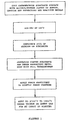
- FIG. 1 Shown in FIG. 1 is a method of joining a dense refractory metal body to a carbonaceous support embodying various features of the invention.
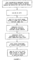
- FIG. 2 Shown in FIG. 2 is an alternative method of joining a dense refractory metal body to a carbonaceous support embodying various features of the invention.
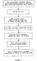
- FIG. 3 Shown in FIG. 3 is another alternative method of joining a dense refractory metal body to a carbonaceous support embodying various features of the invention.
- a dense refractory metal body of tungsten or molybdenum to a carbonaceous substrate having a relatively low coefficient of thermal expansion (CTE), including carbon-carbon composites
- CTE coefficient of thermal expansion
- a refractory metal boride and a Reactive metal carbide By "dense body of tungsten or molybdenum", for purposes of this application, is meant a body having a density at least 80% of its theoretical maximum density (preferably at least about 90% and more preferably at least about 95%), which body contains elemental tungsten, elemental molybdenum or an alloy of either that respectively comprises at least about 90% tungsten or 90% molybdenum.
- Reactive metal is meant a metal having a melting point of about 1600°C or above which forms a carbide and which forms a eutectic with either Mo or W at a temperature below its melting point and below the respective melting point of Mo or W; elements from Groups IVb and Vb of the Periodic Table are preferred, with elements of Group IVb being more preferred and Hf and Zr being most preferred.
- the CTE of tungsten is about 4.5 x 10 -6 /°C
- the CTE of molybdenum is about 5.43 x 10 -6 /°C
- a carbonaceous substrate e.g. a fibrous composite substrate may have a CTE of about 1 x 10 -6 /°C in the direction of orientation of the fibers whereas dense graphite substrates can vary from about 3-9 x 10 -6 /°C
- Carbonaceous supports including graphite, pyrolytic graphite, fiber-reinforced pyrolytic graphite and carbon-carbon composites.
- Carbon-carbon composites wherein carbon fibers are embedded in a carbon matrix, have become widely available in recent years and can be created with very good structural properties; accordingly, they have become one preferred material for use in high temperature structural applications, including use as a support base for a rotating x-ray anode.
- Such a carbon-carbon composite will generally have a density of at least about 1.7 g/cm 3 and an emissivity in the range of about 0.85 to 0.99 so as to allow for adequate dissipation of heat.
- Such composites may be fashioned from lay-ups having various orientations of carbon fiber arrays or graphite fiber cloths, and often they are fashioned from woven carbon fiber fabric or from bundles or tows of carbon fiber filaments that are suitably aligned in generally parallel fashion in alternating layers, although carbon-carbon composites having a three-dimensional carbon frameworks may also be used and may be preferred.
- the orientation is preferably such that the alignment of some of the bundles of fiber or of the woven sheets is transverse to, preferably perpendicular to, the juxtaposed surface of the refractory metal body being joined.
- the carbon fibers or filaments that are present in such composites have higher tensile strength in the axial direction, and because they are preferably aligned transverse to the surface of joinder, the joint will be stronger.
- the joint will be stronger.
- there is a three-dimensional carbon fiber framework there will always be some carbon fibers that will be oriented transverse to any surface.
- Traditional carbonaceous supports for x-ray tube anodes utilize graphite having a density of at least about 75% of theoretical density.
- Graphite has a number of different crystalline forms, and the preferred graphite forms for use as a rotating anode support are those having a relatively high CTE approaching that of the metallic body.
- isotrophy is not considered to be a criterion of major importance, preferred graphites are those that would be categorized as being isotropic, as opposed to anisotropic.
- Such graphites are readily commercially available, as from Toyo Tanso and the Poco Graphite Co.
- One preferred graphite is Toyo Tanso grade IG-610U.
- the joint should provide a thin but effective barrier to carbon diffusion therethrough from the support to the anode body. It is felt that a joint should preferably be constructed to retard the diffusion or migration of carbon from the support body; otherwise, a carbide zone may be formed not only within the region of the initial joint itself, but throughout an expanded region intruding into the surface regions of the anode. Such diffusion-resistance may be particularly of value in the field of x-ray anodes where longevity and continued high thermal conductivity during operation in a high temperature environment are important, because the thermal conductivity of such a metal carbide is substantially lower than that of the bodies being joined. Moreover, a fairly thick carbide zone is more prone to develop cracks as a result of thermal cycling because of inherent differences in CTEs.
- reaction brazing results in the creation of a relatively thin, strong joint of good overall thermal conductivity.
- a particulate mixture of either Hf carbide or Zr carbide and Mo boride may be used which preferably comprises a major portion of the metal carbide and a minor portion of the metal boride.
- tungsten powder in combination with either hafnium or zirconium powder would preferably be used as a minor part of the particulate mixture being employed in the reaction brazing.
- the particles in such mixtures may range in size up to about 50 ⁇ m; however, preferably particles having an average size in the range of about 5 ⁇ m to about 25 ⁇ m and more preferably particles with an average size between about 5 ⁇ m and about 15 ⁇ m are used.
- the metal carbide will be present in an amount at least about 2-3 times the weight of the metal boride and more preferably about 2.5 to 3.5 times the weight of the metal boride.
- Such mixtures of particulate metal carbide and particulate refractory metal boride can be slurried with an alcohol and with a binder, such as a cellulose derivative, to create an adherent, paste-like material that can be conveniently first brushed as a viscous fluid onto the surface in question.
- the mixture being coated onto the carbonaceous substrate preferably also includes minor amounts of the elemental metals that are present in the carbide and boride constituents; for example, molybdenum or tungsten powder and hafnium or zirconium powder may be present, e.g. in individual amounts equal to about 10 to 20 weight % of the total particulate mixture.
- the particle size of the elemental metals can be about the same as set forth above, or they may be slightly smaller. As a general rule, such elemental metal powders are each preferably employed in an amount about equal to or within about 25% of the weight of the boride.
- the amount of Mo or W powder should be approximately equal to the amount of Hf or Zr.
- Mo or W powder is preferably not employed at a weight percentage that is more than about 20% greater or less than that for the Hf or Zr, and preferably there is not more than about a 10% difference in the weight percents. They are most preferably employed in about equal amounts.
- the particulate mixture preferably consists essentially of between about 14% and about 20% by weight of the refractory metal boride, between about 45% and 56% by weight of the Reactive metal carbide, and between about 13% and about 19% each of Hf and Mo powders. More preferably, the mixture contains between about 15% and about 19% of MoB or WB and between about 46% and about 55% of hafnium or zirconium carbide, with the remainder preferably being essentially equal amounts of elemental hafnium and molybdenum.
- the surface may be heated to a temperature sufficient to sinter the boride and carbide particles, as depicted in FIG. 2, under vacuum conditions or in an inert atmosphere which is essentially devoid of O 2 , N 2 , H 2 , CO, CO 2 and SO x , (except for trace amounts such as might be present in high purity commercial gases), all of which are considered to be potentially deleterious to achieving strong bond having long-term stability.
- the time and temperature of the reaction-sintering step is adjusted as well known to those having skill in this art, depending upon the particular compounds that are present.
- a reaction-sintering step might be carried out at a temperature of about 1850 to about 1950°C for about 20 to 30 minutes, after raising the coated substrate reasonably slowly to this temperature.
- a reaction-sintering step might be carried out at a temperature of about 1850 to about 1950°C for about 20 to 30 minutes, after raising the coated substrate reasonably slowly to this temperature.
- a boride of the same refractory metal as the dense body that is to be joined is preferred, there are other options.
- one or more other compatible refractory or Reactive metal borides such as tungsten boride, vanadium boride and/or zirconium boride, may be used either together with, or to the exclusion of, Mo boride.
- the tungsten boride may be WB, W 2 B or W 2 B 5 ; however, preferably W 2 B is used, particularly when a W body is being bonded.
- the molybdenum boride may be MoB 2 , MoB, Mo 3 B 4 or Mo 3 B 5 ; preferably, however, MoB is used.
- a relatively thin, but continuous layer of such particulate material slurry is preferably applied so that the final thickness of the joint is about 0.18 mm (0.007 in) or less, preferably not greater than about 0.13 mm 0.005 in and more preferably about 0.08 mm (0.003 in) plus or minus 0.03 mm 0.001 in.
- hafnium carbide is the more preferred carbide
- zirconium carbide might be substituted for part or all of the Hf carbide.
- either might be used together with particles of molybdenum carbide, vanadium carbide, or tungsten carbide in the slurry for coating the carbonaceous surface.
- the second step of the preferred, somewhat lower temperature joining method introduces a layer of Hf or Zr between the surface of the dense refractory metal body and the reaction-sintered surface of the carbonaceous support; thereafter, reaction-brazing is carried out.
- the layer can be one of a dense paste of metal particles or metallic foil.
- Metal foil is preferably used, and it may be in the form of sheet material about 1-3 mils 0.0025-0.076 mm in thickness. It is placed adjacent the surface of the dense refractory metal body to be joined and can be a single sheet or multiple sheets, depending in part on what is commercially available. For example, two sheets of 0.0254 mm (0.001 in) thick hafnium foil may be used to provide a layer 2 mils in thickness.
- the foil layer is simply located atop the air-dried slurry-coated carbonaceous substrate.
- the introduction of a continuous layer of a paste mode of small Reactive metal particles is feasible but much less desirable.
- the dense refractory metal body is juxtaposed, and the reaction-sintering step is carried out.
- the composition of the reaction braze material will be essentially the same.
- the material should include a mixture of a refractory metal boride and a Reactive metal carbide, preferably with additional compatible elementary Reactive and refractory metals, e.g. Hf and Mo powder.
- the braze material is applied as a mixture of a binder and such particulate materials, preferably as an alcohol slurry of a binder and the particulate/powder mixture, using a suitable alcohol, such as ethyl alcohol.
- a suitable alcohol such as ethyl alcohol.
- a cellulose derivative or a comparable organic binder, that will be removed by dissociation and volatilization during the subsequent heating to the reaction-sintering temperature, is preferably used to create a fluid mixture having the consistency of a flowable paste that can be uniformly brushed or otherwise suitably applied onto the carbonaceous surface.
- the braze material coating is heated in air to cure the binder. For example, heating to 125°C for about 12 hours will partially polymerize a cellulose binder and vaporize the alcohol. Clean foil which is free of contaminants is then placed to cover the overall coated surface of the substrate, and the dense refractory metal body is lightly pressed thereatop, sandwiching the foil therebetween to prepare the assembly for the thermal braze cycle. Either gravity or preferably a small weight placed atop the dense refractory body is relied upon during the reaction-brazing cycle to maintain the surfaces in juxtaposition with each other. For example, it may be desirable to have a pressure of about 1380 Pa (0.2 to 0.8 psi) on the foil.
- the thermal cycle which is used will generally include staged heating as described hereinafter to a temperature at or near that of the desired reaction-brazing temperature.
- the staged heating up to the reaction-brazing temperature will usually take place over at least 1 hour and preferably over about 2 hours or more.
- the reaction-brazing temperature should then be held for a period of at least 10 minutes, more preferably at least about 15 minutes, and most preferably over at least about 20 minutes.
- solid state reaction wherein there will be such a metallic alloy zone on the Mo body (or W body) side of the carbide layer.
- a metallic alloy zone on the Mo body (or W body) side of the carbide layer.
- it may be a solid solution of Hf and HfMo 2 that, at and above the eutectic temperature, forms a liquid solution of about 28 weight % Mo and about 72 weight % Hf which dissolves some MoB and carbon; however, there is a reversal during cooling below 1865°C where an Hf-rich solid solution and the compound HfMo 2 form from the liquid phase.
- One example of the preparation of a carbon-carbon composite suitable for joinder as a support for an x-ray anode employs commercially available carbonaceous material which is at least about 1,27 cm in thickness and which has Z-axis fiber bundles that are oriented substantially perpendicular to the surface at which bonding is to be achieved.
- the composite is cleaned in ethanol using ultrasonic cleaning and then baked under vacuum conditions at about 1000°C for an hour, followed by baking at a temperature of about 2600°C for about 10 to 15 minutes, to remove any volatiles that might otherwise potentially have an adverse effect upon the integrity of the joint.
- One preferred alternative material is dense graphite such as that available from the Toyo Tanso Co. of Japan as their grade:IG-610U.
- the graphite is preferably isotropic and should have a density of at least about 75% of its theoretical density of 2.26 gm/cm 3 , e.g. about 77 to 80%; it should have a coefficient of thermal expansion of at least about 5 x 10 -6 /°C, but preferably not greater than about 6 x 10 -6 /°C. Such graphite should also have a thermal conductivity of at least about 100 W/m°C.
- the preferred brazing material is a slurry of a mixture of particulates together with an organic binder in a suitable organic solvent, e.g. ethyl alcohol.
- the binder may be a cellulose compound, such as hydroxypropylcellulose, or any other commercially available organic binder that will be removed as a result of heating under vacuum conditions or leave no more than a minute carbon residue.
- the metal carbide particles and the refractory metal boride particles may be of about the same size range. Generally, the particle sizes between about 50 ⁇ m and about 5 ⁇ m may be used, and particles which pass through a 325 mesh (45 ⁇ m) screen may be used, but particles between about 5 ⁇ m and about 15 ⁇ m are generally preferred.
- elemental Reactive and refractory metals may also be used in the same particle size range, these materials are commercially available in powder form; thus, molybdenum and/or tungsten and hafnium and/or zirconium are conveniently supplied as powders in a size between about 20 ⁇ m and about 5 ⁇ m.
- the slurry layer is preferably applied in a thickness so as to result in a joint which is about 2 mils (about 50 ⁇ m) thick without the contribution of the foil.
- the reaction-brazing temperature will vary somewhat depending upon the materials that are being used, but the assembly will generally be held at such temperature for at least about 15 minutes. Very generally, a temperature well below the melting point of the dense refractory metal, i.e. molybdenum or tungsten, is chosen so that melting of such clearly does not occur. However, the temperature should be sufficiently high so that a eutectic is formed between the foil, a minor amount of the metal powder and the Mo or W material at the surface being bonded; this eutectic takes part in creating a strong bond at this surface during the reaction-brazing step.
- molybdenum is considered to have a melting point of about 2890°K (2617°C), and whereas alloys of Mo with hafnium (M.P. of 2503°K, 2230°C) have a measured eutectic point at about 1930°C, it appears to be depressed to about 1865°C as a result of the presence of carbon and the boride phase.
- operation can be carried out at a temperature slightly below the measured eutectic point for a system using the two metals, i.e. molybdenum and hafnium, and will produce a very effective braze as part of this overall novel joining method.
- a reaction-brazing temperature between about 1835°C and 1895°C is preferred, with a temperature between about 1850°C and about 1880°C being more preferred and a brazing temperature of about 1865°C being most preferred.
- the measured eutectic temperature of Zr (M.P. of 2125°K, 1852°C) and Mo is lower, i.e. about 1520°C; accordingly, such a reaction-brazing might be carried out at a temperature below 1500°C, e.g. about 1460°C, or at a higher temperature if desired.
- pure tungsten and zirconium form a eutectic at a temperature of about 1660°C, so temperatures about 20 to 30°C below this may be suitable for reaction-brazing using a comparable mixture containing W and Zr.
- somewhat higher brazing temperatures e.g.
- a higher temperature operational joint may be produced, as described hereinafter, by reaction-brazing W to C using a particulate mixture of WB and HfC or WC that is devoid of significant amounts of elemental metals so that the eutectic does not include contribution from an elemental Reactive metal.
- the amount of alcohol and/or organic binder in the mixture is not particularly critical so long as potential separation of the various particle fractions is prevented, i.e. to prevent partitioning as a result of different weights or densities. It is generally satisfactory that a sufficient amount of binder is used so as to provide integrity in the coated layer, i.e. so that it will remain in place on the surface and there will be uniformity of particle distribution throughout.
- the thickness of the coated layer will usually be about 0.076 mm (0.5 mil and about 3 mils) and preferably about 0.051 mm (1 mil and 2 mils).
- the foil sheet or sheets are then positioned thereatop and sandwiched between this coated surface and the dense refractory metal body being joined.
- a weight is preferably added to the assembly so that gravity will create a light pressure during the reaction-brazing step.
- the amount of weight should be equal to the weight of the dense refractory metal body plus or minus about 50%; in one experiment, weight was added to create a normal pressure stress of 0.00276 MPa (0.4 lb/in 2 ) which proved adequate.
- the heating preferably the cool-down
- stages may be varied with some amount of latitude; for example, the temperature may be raised at a substantially linear rate from ambient to about 700°C over a time of about 60 to 90 minutes, although a shorter period may be used. Thereafter, the temperature is preferably raised to the desired reaction-brazing temperature in two or three increments, with brief soakings preferably being used at such intermediate incremental temperatures to assure that temperature gradients within the assembly are minimized.
- a slower rate is preferred to enable any liquid phase to solidify uniformly in place within the assembly, thereby preventing radial flow and the potential creation of voids in the joint.
- Preparations are made to join a graphite ring machined to have an outer diameter of about 13.59 cm (5.35 inches) and an inner diameter of about 2 inches (5.08 cm) to a disk of TZM (molybdenum alloy) of about the same outer diameter (about 5.25 in) which has a central hole of 0.5 inches (1.3 cm) and a thickness of 0.416 inch (1.06 cm) at its greatest thickness.
- the TZM disk has a flat lower surface and a beveled top surface so that its thickness is greater in the center at the region of the half-inch hole.
- the graphite ring is machined from IG-61OU near-isotropic, medium grain, fine porosity graphite having a CTE of about 6 x 10 -6 /°C, which is relatively close to the CTE of molybdenum, i.e. 5.43 x 10 -6 /°C.
- the graphite ring has a thickness of about 5,08 cm (2 inches) at its center and a bevel toward its outer circumference.
- the planar face of the graphite ring was ground using abrasive paper having a silicon carbide grit of Mesh Size No. 240 and then cleaned using ultrasonic cleaning in ethanol. After pumping the cleaned part free of alcohol under vacuum, it was subjected to a high temperature bake-out along with a similarly cleaned 3/4 inch diameter graphite sample that was to be used as a process control and microstructure analysis specimen. Heating of the graphite parts was carried out for about 30 minutes at 1920°C under a vacuum of about 1,33 ⁇ 10 -7 Pas. This bake-out releases and disperses any volatiles that might otherwise be released during the subsequent reaction-sintering and potentially form undesirable porosity in the liquid phase of the reaction-braze material.
- a brazing slurry is then formed from a particulate/powder mixture in alcohol, i.e. ethanol, using a solution of 99 parts ethanol and 1 part hydroxypropylcellulose, which was stirred to obtain a solution of transparent clarity and stored so as to prevent absorption of water from the atmosphere.
- alcohol i.e. ethanol
- All of the powders used had greater than 99.5% purity. All were of less than 325 mesh size (about 45 ⁇ m), and most of them had an average particle size of about 10 ⁇ m, being generally between about 5 ⁇ m and about 20 ⁇ m.
- the powder mixture was formulated using four different powders in the following weight percents: Hf - 16%, Mo - 16%, MoB - 17% and HfC - 51%.
- the top surfaces of the graphite ring and the 1,91 cm (3/4 inch) diameter graphite cylinder were then coated with the powder slurry.
- the graphite ring weighed about 886 grams, and about 4 grams of the powder slurry were applied uniformly across the flat face of the graphite ring that had an area of about 125 cm 2 (19.33 in 2 ), i.e. about 1 gram of powder slurry per 32,8 cm 2 (5 sq. in). Paint was carried out by hand using an artist-quality bristle paint brush. The slurry was applied in layers and allowed to air dry.
- the graphite ring and the test cylinder were periodically weighed until the desired amount of the powder mixture had been applied to both.
- the graphite parts with the powder slurry-coated faces positioned upwards and horizontal, were heated in a convection oven at about 125°C allowing the cellulose binder to cure in air over 9 to 10 hours, during which time ethanol and any water that might be present evaporated. The parts were then removed, allowed to cool and then associated with hafnium foil.
- Two rings of hafnium foil each about 0.001 in. (0.025 mm) thick, were used; each had an O.D. just slightly less than the O.D. of the graphite ring and slightly greater than the O.D. of the TZM ring, which is about 5.25 in.(13.34 cm) and an LD. slightly smaller than the I.D. of the graphite rim.
- Assemblies are then created with the hafnium foil disposed horizontally upon the slurry-coated flat surfaces of the graphite support and with the TZM ring resting upon the Hf foil.
- a similar TZM disk having a flat lower surface is used to overlie two circular disks of Hf foil on the test cylinder.
- the two assemblies were then transferred to a vacuum furnace having tungsten heating elements disposed within a water-cooled exterior boundary, which was then evacuated to about 1,2 ⁇ 10 -8 bar. Heating was carried out at a rate of about 600°C per hour until a temperature of about 700°C was reached, at which time the temperature was held for about 5-15 minutes (soaking). The rate of heating was then increased to about 1,000°C per hour, which rate was thereafter used. Once the target temperature of 1200°C was reached, it was held for 5-10 minutes, and after 1600°C was reached, it was held for about 10-20 minutes. Heating was then continued to about 1865°C, the desired reaction-brazing temperature, and the assembly was held at this temperature for 20-30 minutes at a furnace pressure of about 1,33 ⁇ 10 -7 bar.
- the Hf foil becomes joined to the Mo alloy body by solid-state diffusion reaction and by the eutectic reaction, i.e. solid Hf (alloyed with Mo) phase + HfMo 2 phase forms liquid eutectic phase at eutectic temperatures.
- the assemblies were slowly cooled at a rate of about 200°C per hour for the first 100° and held at about 1765° for about 10 minutes. Cooling at the same rate to 1600° was then effected, and this temperature was held for about 1 minute. The rate of cooling was then increased to about 1000°C per hour until about 600°C, where the rate gradually slowed as radiative cooling efficiency begins to diminish.
- ambient temperature was reached, e.g. below about 40°C, the furnace vacuum was ended, and pressure was returned to atmospheric.
- the cross-section was prepared and then examined in a scanning electron microscope to observe the microstructure in the joint region and check for any voids or large pores, cracks or other nonuniformities; none were found. Measurements of the joint thickness were made, and the thickness was found to be between about 0.064 and about 0.076 mm (0.0025 and 0.003 inch).
- Example I A procedure as generally set forth in Example I is carried out using a 2-inch diameter graphite ring and a TZM disk of comparable size. Following application of the slurry to the flat surfaces of the graphite ring substrate and a test cylinder, they are reaction-sintered in accordance with the two-step process depicted in FIG. 2.
- the coated graphite supports are placed in the vacuum furnace under the same vacuum conditions and heated to a temperature of about 1945°C over a time period of about 2 hours and 30 minutes using a very similar heating schedule to that previously described. Once this reaction-sintering temperature is reached, the coated supports are held at this temperature for about 30 minutes. Thereafter, heating is discontinued, and the furnace is cooled to ambient temperature using a schedule essentially the same as in Example I.
- Example I Thereafter, the two rings of hafnium foil are inserted atop the sintered layer, and a TZM disk is placed thereatop and weighted generally as described in Example I.
- the test cylinder is separately assembled as before.
- the assemblies are then returned to the vacuum furnace, and reaction-brazing is carried out using the time and temperature schedule set forth in Example I heating to a temperature of about 1865°C.
- the assemblies are removed, and examination and cross-sectioning of the test cylinder show that a strong, uniform joinder of the bodies has been achieved.
- Example II sample and a comparable 5,08 cm diameter sample fabricated according to the process of Example I are soaked for about 50 hours at about 1600°C in the vacuum furnace under a vacuum of about 1,33 ⁇ 10 -7 bar. Following such soaking at 1600°C, the samples are caused to cycle between 1600°C and 750°C, being repeatedly allowed to drop over about 50 minutes to 750°C before raising the temperature back to 1600°C over the next 50 minutes. This process is repeated 20 times so that the samples have each been subjected to 21 thermal cycles.
- the samples are held at the 1600°C level for about 10 minutes and are similarly held at the 750°C level for about 10 minutes; this constitutes a severe test cycle designed to test the suitability of the product to withstand the cycling that a rotating anode would be expected to experience.
- the joined bodies are examined by X-ray radiography and otherwise, and the bonds appear to be continuous and strong.
- the samples are cross-sectioned transverse to the joint and subjected to metallographic examination, it is seen that the thickness of the joint has not grown and that there are only minor amounts of molybdenum carbide and molybdenum boride phases in the grain boundaries of the TZM body adjacent to the joint microstructure of the assemblies made using the one-step method of Example L
- a very thin continuous layer of hafnium-rich carbide (equal to about 20% of the thickness of the joint) extends throughout the entire circular area and has remained substantially the same thickness as when it was formed by reaction-brazing.
- Example II sample shows a quite similar joint microstructure; however, there is included a thin zone of molybdenum carbide/boride phase that is formed generally adjacent the eutectoid rich zone of the joint that appears to have resulted from C and B diffusion during the high temperature test exposure following the initial reaction-sintering step.
- the joint thickness has remained about the same and prevented growth of a thick carbide zone into the TZM alloy body, the sample retains good thermal conductivity across the bond (as does the sample from the method of Example I) which is an important feature for a rotating x-ray anode.
- a procedure as generally set forth in Example I is carried out using a 2-inch diameter carbon-carbon composite ring and a single crystal W disk of comparable size.
- a brazing slurry is formed from a particulate/powder mixture in alcohol, i.e. ethanol, using a solution of 99 parts ethanol and 1 part hydroxypropylcellulose.
- the powder mixture is formulated using equal weight percents of tungsten boride and tungsten carbide and is mixed to achieve 10 parts of this powder mixture in 6 parts by weight of the cellulose alcohol solution.
- top surfaces of the carbon-carbon ring and the test cylinder are coated with the powder slurry by painting by hand using an artist-quality bristle paint brush.
- the slurry is applied in layers and allowed to air dry.
- the ring and the test cylinder are periodically weighed until the desired amount of the powder mixture has been applied to both.
- the carbon-carbon parts with the slurry-coated faces positioned upwards and horizontal, are heated in a convection oven at about 125°C allowing the cellulose binder to cure in air over 9 to 10 hours, during which time ethanol and any water that might be present evaporate.
- the parts are then removed, allowed to cool and then reaction-sintered as generally depicted in FIG. 3.
- the coated carbon-carbon supports are placed in a high temperature furnace under the same vacuum conditions; the furnace is back-filled with argon and heated to a temperature of about 2350°C over a time period of about 1 hour using a heating schedule similar but more rapid than that previously described. Once this reaction-sintering temperature is reached, the coated supports are held at this temperature for about 7 minutes. Thereafter, heating is discontinued, and the furnace is cooled to ambient temperature using a schedule essentially the same as in Example I.
- each sintered layer is coated with a second layer of the same slurry material, which may optionally include up to about 5% of carbon powder, and then similarly air-dried.
- a single-crystal W disk is placed thereatop and weighted generally as described in Example I.
- the test cylinder is separately assembled as before with a similar W disk.
- the assemblies are then returned to the vacuum furnace, and reaction-brazing is carried out in vacuum, or optionally in inert gas, using a time and temperature schedule generally as set forth in Example I but heating to a final temperature of about 2350°C and holding that temperature for about 10 to 15 minutes.
- Example II Following cooling down under a similar schedule as that in Example I, the assemblies are removed, and examination and cross-sectioning of the test cylinder show that a strong, uniform joinder of the bodies is achieved and that the single crystal W disc will be excellently suited for use as a rotating anode in commercial x-ray tubes because its character will allow its operation at a temperature as high as about 85% of the reaction-brazing temperature, e.g. about 2000°C.
Abstract
Description
Claims (12)
- A method of joining a dense tungsten W or molybdenum Mo body to a carbonaceous support, which method comprisesproviding a dense W or Mo metal body, which body has one surface designated for joinder to another body,providing a carbonaceous support body capable of withstanding high temperatures in the absence of air, which support has a surface complementary to said designated surface of said dense body,coating said complementary surface of said support body with a layer of a material comprising a mixture of particles of a refractory metal boride and particles of a metal carbide,juxtaposing said two complementary surfaces, andjoining said dense body to said carbonaceous support body by heating to a reaction-brazing temperature such that said refractory metal body thereafter strongly adheres to said carbonaceous support while an intermediate barrier forms between said two bodies which thereafter diminishes diffusion of carbon from said support body into said refractory metal body.
- The method of claim 1 wherein said mixture also contains particulate refractory metal and particulate Reactive metal and wherein said heating raises the temperature to near or at the eutectic temperature for a solution comprising the metal of said dense body, said Reactive metal, carbon, said metal boride and any compound formed between said Reactive metal and said W or Mo.
- The method according to claim 1 wherein said dense body is a molybdenum body, said boride is Mo boride, said carbide is HfC and said particulate mixture contains Hf and Mo powder, and wherein said heating is to a temperature of about 1865°C.
- The method according to claim 1 wherein said metal boride is a boride of W, Mo, vanadium, V or zirconium, Zr and wherein said metal carbide is a carbide of hafnium Hf, Zr, Mo or W.
- The method according to claim 3 or 4 wherein said heating raises the temperature to a temperature which is at or near the eutectic temperature for a solution comprising the metal of said dense body, said metal boride, carbon, said Reactive metal and any compound formed between said Reactive metal and W or Mo.
- The method according to claim 4 wherein said coating material is an alcohol slurry containing particles of tungsten boride or molybdenum boride and hafnium carbide or zirconium carbide having particle size of about 50 µm or less.
- The method in accordance with any one of claim 1-6 wherein a Reactive metal layer comprising foil of elemental Hf or Zr is introduced between said two juxtaposed complementary surfaces, and wherein said mixture also includes elemental Hf or Zr powder and elemental Mo or W powder.
- The method in accordance with claim 7 wherein said coating material includes a particulate mixture which consists essentially of between about 14% and 20% by weight of said metal boride, between about 45% and 56% by weight of said metal carbide, between about 13% and 19% by weight of elemental Hf and/or Zr powders and about 13% to 19% of elemental W or Mo.
- The method according to any one of claims 1-8 wherein said carbonaceous support body is graphite or a carbon-carbon composite, and wherein force is applied to press said surfaces into juxtaposition with each other while heating in a vacuum to said reaction-brazing temperature which is maintained for a period of at least about 15 minutes.
- The method according to any one of claims 1-9 wherein said dense body is of single-crystal material and said carbonaceous support body is a carbon-carbon composite containing carbon fibers that are aligned transverse to the surface to be placed in juxtaposition with said dense body.
- The method according to claim 1 wherein said dense body is a target anode for creating x-rays and wherein said body is joined to said carbonaceous support by heating to a reaction-brazing temperature of at least about 2200°C.
- The method according to claim 1 wherein said dense body is a dense Mo body, suitable as a target anode to create x-rays, said complementary surface of said support body is coated with a layer containing a mixture of particles of Mo boride, Hf carbide and/or Zr carbide, elemental Mo, and elemental Hf and/or Zr, and said two complementary surfaces are juxtaposed with Hf or Zr metal foil therebetween and heated to a temperature at or near the eutectic temperature for a solution comprising Mo, MoB, and Hf and/or Zr, which is maintained for time sufficient for Mo and Hf and/or Zr to form carbides by reaction at the surface of said carbonaceous support body.
Applications Claiming Priority (3)
| Application Number | Priority Date | Filing Date | Title |
|---|---|---|---|
| US900252 | 1997-07-25 | ||
| US09/900,252 US6554179B2 (en) | 2001-07-06 | 2001-07-06 | Reaction brazing of tungsten or molybdenum body to carbonaceous support |
| PCT/US2002/020899 WO2003038857A1 (en) | 2001-07-06 | 2002-07-02 | Reaction brazing of tungsten or molybdenum body to carbonaceous support |
Publications (2)
| Publication Number | Publication Date |
|---|---|
| EP1407468A1 EP1407468A1 (en) | 2004-04-14 |
| EP1407468B1 true EP1407468B1 (en) | 2005-09-28 |
Family
ID=25412236
Family Applications (1)
| Application Number | Title | Priority Date | Filing Date |
|---|---|---|---|
| EP02797023A Expired - Lifetime EP1407468B1 (en) | 2001-07-06 | 2002-07-02 | Reaction brazing of tungsten or molybdenum body to carbonaceous support |
Country Status (7)
| Country | Link |
|---|---|
| US (1) | US6554179B2 (en) |
| EP (1) | EP1407468B1 (en) |
| JP (1) | JP4237059B2 (en) |
| AT (1) | ATE305660T1 (en) |
| DE (1) | DE60206382T2 (en) |
| HK (1) | HK1065165A1 (en) |
| WO (1) | WO2003038857A1 (en) |
Families Citing this family (30)
| Publication number | Priority date | Publication date | Assignee | Title |
|---|---|---|---|---|
| EP1368154A4 (en) * | 2001-02-05 | 2005-06-15 | Univ Rutgers | Transient eutectic phase process for ceramic-metal bonding, metallilzation, and compositing |
| DE10301069B4 (en) * | 2003-01-14 | 2007-08-02 | Siemens Ag | Thermally resilient material composite of a fiber-reinforced and another material |
| FR2858332B1 (en) * | 2003-07-31 | 2005-10-28 | Cezus Co Europ Zirconium | METHOD FOR MANUFACTURING A ZIRCONIUM ALLOY FLAT PRODUCT, FLAT PRODUCT THUS OBTAINED, AND COMPONENT FUEL ASSEMBLY ELEMENT FOR NUCLEAR POWER PLANT REACTOR PRODUCED FROM THE FLAT PRODUCT |
| AT6994U1 (en) * | 2003-10-03 | 2004-07-26 | Plansee Ag | METHOD FOR PRODUCING A COMPOSITE BODY |
| US7194066B2 (en) * | 2004-04-08 | 2007-03-20 | General Electric Company | Apparatus and method for light weight high performance target |
| ITRM20040368A1 (en) * | 2004-07-20 | 2004-10-20 | Enea Ente Nuove Tec | JOINTING PROCEDURE OF A CERAMIC MATERIAL AND A METALLIC MATERIAL WITH THE INTERPOSITION OF A TRANSITIONAL MATERIAL. |
| CN100503872C (en) * | 2004-11-09 | 2009-06-24 | 岛根县 | Metal-based carbon fiber composite material production method |
| DE102006038417B4 (en) * | 2006-08-17 | 2012-05-24 | Siemens Ag | X-ray anode |
| US7648675B2 (en) * | 2006-10-06 | 2010-01-19 | Zhang Shi C | Reaction sintered zirconium carbide/tungsten composite bodies and a method for producing the same |
| US20090060139A1 (en) * | 2007-08-28 | 2009-03-05 | Subraya Madhusudhana T | Tungsten coated x-ray tube frame and anode assembly |
| US9159523B2 (en) | 2007-08-28 | 2015-10-13 | General Electric Company | Tungsten oxide coated X-ray tube frame and anode assembly |
| US8059785B2 (en) * | 2007-09-06 | 2011-11-15 | Varian Medical Systems, Inc. | X-ray target assembly and methods for manufacturing same |
| US7672433B2 (en) * | 2008-05-16 | 2010-03-02 | General Electric Company | Apparatus for increasing radiative heat transfer in an x-ray tube and method of making same |
| US8165269B2 (en) * | 2008-09-26 | 2012-04-24 | Varian Medical Systems, Inc. | X-ray target with high strength bond |
| EP2194564B1 (en) * | 2008-12-04 | 2013-05-22 | Varian Medical Systems, Inc. | X-ray target assembly and methods for manufacturing same |
| EP2380183B1 (en) | 2008-12-17 | 2012-08-15 | Koninklijke Philips Electronics N.V. | Attachment of a high-z focal track layer to a carbon-carbon composite substrate serving as a rotary anode target |
| DE102009014407A1 (en) * | 2009-03-28 | 2010-10-21 | Sgl Technologies Gmbh | Adhesive-free, temperature- and reaction-stable bonding between metals and graphite |
| EP2449572B1 (en) | 2009-06-29 | 2017-03-08 | Koninklijke Philips N.V. | Anode disk element comprising a heat dissipating element |
| US8580593B2 (en) * | 2009-09-10 | 2013-11-12 | Micron Technology, Inc. | Epitaxial formation structures and associated methods of manufacturing solid state lighting devices |
| US20110135956A1 (en) * | 2009-12-08 | 2011-06-09 | General Electric Company | Method of joining materials, and articles made therewith |
| AT12919U1 (en) * | 2011-11-25 | 2013-02-15 | Plansee Se | METHOD FOR PRODUCING A HIGH-TEMPERATURE-RESISTANT COMPOSITE BODY |
| US8865301B2 (en) | 2012-01-26 | 2014-10-21 | The United States Of America, As Represented By The Secretary Of The Navy | Refractory metal boride ceramics and methods of making thereof |
| WO2013165538A1 (en) * | 2012-05-01 | 2013-11-07 | The Government Of The Usa, As Represented By The Secretary Of The Navy | Formation of boron carbide-boron nitride carbon compositions |
| US9573354B2 (en) | 2013-03-15 | 2017-02-21 | Rolls-Royce Corporation | Layered deposition for reactive joining of composites |
| US9366140B2 (en) | 2013-03-15 | 2016-06-14 | Rolls-Royce Corporation | Ceramic matrix composite repair by reactive processing and mechanical interlocking |
| PL3135082T3 (en) * | 2014-04-24 | 2021-09-13 | Triumf | Target assembly for irradiation of molybdenum with particle beams and method of making thereof |
| US9711320B2 (en) | 2014-04-29 | 2017-07-18 | General Electric Company | Emitter devices for use in X-ray tubes |
| US11373833B1 (en) | 2018-10-05 | 2022-06-28 | Government Of The United States, As Represented By The Secretary Of The Air Force | Systems, methods and apparatus for fabricating and utilizing a cathode |
| CN112930027A (en) * | 2021-01-18 | 2021-06-08 | 成都宏科电子科技有限公司 | White alumina ceramic substrate metallized pore-filling tungsten slurry and preparation method thereof |
| CN115255703A (en) * | 2022-08-31 | 2022-11-01 | 武汉工程大学 | Graphite-molybdenum joint and preparation method thereof |
Family Cites Families (22)
| Publication number | Priority date | Publication date | Assignee | Title |
|---|---|---|---|---|
| AT278184B (en) | 1967-08-28 | 1970-01-26 | Plansee Metallwerk | Rotating anode for X-ray tubes |
| AT278983B (en) | 1968-08-12 | 1970-02-25 | Plansee Metallwerk | Process for the production of rotating anodes for X-ray tubes |
| AT285185B (en) | 1968-12-23 | 1970-10-12 | Plansee Metallwerk | Sintered tungsten alloy |
| DE1951383C3 (en) * | 1969-10-11 | 1974-08-29 | Siemens Ag, 1000 Berlin Und 8000 Muenchen | X-ray tube rotating anode with a composite body made from a heavy metal part and at least one graphite part and a method for producing it |
| AT300140B (en) | 1970-06-02 | 1972-07-10 | Metallwerk Plansee Ag & Co Kom | Rotating anode for X-ray tubes |
| US3770487A (en) * | 1971-01-28 | 1973-11-06 | Mc Donnell Douglas Corp | Refractory composites |
| US3821579A (en) | 1971-05-25 | 1974-06-28 | S Burns | X ray source |
| FR2242775A1 (en) * | 1973-08-31 | 1975-03-28 | Radiologie Cie Gle | Rotary anode for X-ray tubes - using pseudo-monocrystalline graphite for better heat conduction |
| AT346981B (en) | 1976-03-18 | 1978-12-11 | Plansee Metallwerk | ROTARY ROTARY ANODE AND METHOD FOR MANUFACTURING IT |
| US4195247A (en) * | 1978-07-24 | 1980-03-25 | General Electric Company | X-ray target with substrate of molybdenum alloy |
| US4394953A (en) * | 1981-03-12 | 1983-07-26 | Schwarzkopf Development Corporation | Method of joining individual parts of an X-ray anode, in particular of a rotating anode |
| AT376064B (en) * | 1982-02-18 | 1984-10-10 | Plansee Metallwerk | X-RAY TUBE ROTATING ANODE |
| AT383758B (en) * | 1985-12-23 | 1987-08-25 | Plansee Metallwerk | METHOD FOR PRODUCING A SPUTTER TARGET |
| AT391223B (en) | 1987-08-03 | 1990-09-10 | Plansee Metallwerk | METHOD FOR PRODUCING A ROTATING ANODE FOR X-RAY TUBES |
| AT387988B (en) * | 1987-08-31 | 1989-04-10 | Plansee Tizit Gmbh | METHOD FOR PRODUCING MULTI-LAYER COATED HARD METAL PARTS |
| AT389832B (en) | 1988-08-01 | 1990-02-12 | Plansee Metallwerk | SOLDER CONNECTION |
| AT392760B (en) | 1989-05-26 | 1991-06-10 | Plansee Metallwerk | COMPOSITE BODY MADE OF GRAPHITE AND HIGH-MELTING METAL |
| AT393651B (en) * | 1990-06-28 | 1991-11-25 | Plansee Metallwerk | HIGH TEMPERATURE RESISTANT COMPOSITE |
| EP0479197B1 (en) * | 1990-10-01 | 1996-08-21 | Kabushiki Kaisha Toshiba | Rotary anode type X-ray tube |
| US5247563A (en) * | 1992-02-25 | 1993-09-21 | General Electric Company | High vapor pressure metal for X-ray anode braze joint |
| JP2720762B2 (en) * | 1993-08-13 | 1998-03-04 | 日本電気株式会社 | How to join graphite and metal |
| US5943389A (en) * | 1998-03-06 | 1999-08-24 | Varian Medical Systems, Inc. | X-ray tube rotating anode |
-
2001
- 2001-07-06 US US09/900,252 patent/US6554179B2/en not_active Expired - Fee Related
-
2002
- 2002-07-02 EP EP02797023A patent/EP1407468B1/en not_active Expired - Lifetime
- 2002-07-02 AT AT02797023T patent/ATE305660T1/en not_active IP Right Cessation
- 2002-07-02 JP JP2003541015A patent/JP4237059B2/en not_active Expired - Fee Related
- 2002-07-02 DE DE60206382T patent/DE60206382T2/en not_active Expired - Fee Related
- 2002-07-02 WO PCT/US2002/020899 patent/WO2003038857A1/en active IP Right Grant
-
2004
- 2004-10-11 HK HK04107819A patent/HK1065165A1/en not_active IP Right Cessation
Also Published As
| Publication number | Publication date |
|---|---|
| WO2003038857A1 (en) | 2003-05-08 |
| JP4237059B2 (en) | 2009-03-11 |
| US6554179B2 (en) | 2003-04-29 |
| HK1065165A1 (en) | 2005-02-08 |
| DE60206382T2 (en) | 2006-06-22 |
| EP1407468A1 (en) | 2004-04-14 |
| ATE305660T1 (en) | 2005-10-15 |
| JP2004523093A (en) | 2004-07-29 |
| DE60206382D1 (en) | 2005-11-03 |
| US20030006269A1 (en) | 2003-01-09 |
Similar Documents
| Publication | Publication Date | Title |
|---|---|---|
| EP1407468B1 (en) | Reaction brazing of tungsten or molybdenum body to carbonaceous support | |
| JP2004523093A5 (en) | ||
| CA2627786C (en) | Braze system with matched coefficients of thermal expansion | |
| JP5665295B2 (en) | Moderately refractory assembly process for SiC-based material articles by non-reactive brazing, brazing composition, and joints and assemblies obtained by this process | |
| US9713860B2 (en) | Compositions for joining and assembling parts made of SiC-based materials | |
| US5447683A (en) | Braze for silicon carbide bodies | |
| JP5978105B2 (en) | Silicon carbide ceramic joined body and method for producing silicon carbide ceramic joined body | |
| US8763883B2 (en) | Method for assembling parts made of SiC materials by non-reactive brazing, brazing compositions, and joint and assembly obtained by said method | |
| JP2013522154A (en) | Method for joining parts made of SiC-based materials by non-reactive brazing using additional reinforcements, brazing composition, and joints and assemblies obtained by such methods | |
| US20130011185A1 (en) | METHOD FOR ASSEMBLING, JOINING PARTS MADE OF SiC-BASED MATERIALS BY NON-REACTIVE BRAZING, BRAZING COMPOSITIONS, AND JOINT AND ASSEMBLY OBTAINED BY SAID METHOD | |
| Casalegno et al. | Surface modification of carbon/carbon composites to improve their wettability by copper | |
| Riccardi et al. | Brazing of SiC and SiC f/SiC composites performed with 84Si-16Ti eutectic alloy: microstructure and strength | |
| CN108517518B (en) | Preparation method of composite coating for improving high-temperature oxidation resistance of titanium alloy | |
| JP2015502910A (en) | Method for assembling an article made of SiC material by non-reactive brazing in an oxidizing atmosphere, brazing composition, and gasket and assembly obtained by the above method | |
| JP5773331B2 (en) | Manufacturing method of ceramic joined body | |
| Wang et al. | A novel process with the characteristics of low-temperature bonding and high-temperature resisting for joining Cf/SiC composite to GH3044 alloy | |
| JP5721321B2 (en) | Method for assembling a moderately fire-resistant article made of SiC-based material by non-reactive brazing of a brazing composition under an oxidizing atmosphere, and the joint and assembly obtained by this method | |
| Wu et al. | Pressureless joining of SiC ceramics at low temperature | |
| Riccardi et al. | Low activation brazing materials and techniques for SiCf/SiC composites | |
| CN111116228A (en) | Preparation method of ablation-resistant ZrC-HfC/SiC double-layer complex phase ceramic coating | |
| Riccardi et al. | High Temperature Brazing for SiC and SiC~ f/SiC Ceramic Matrix Composites | |
| JPH05306180A (en) | Production of carbon fiber reinforced carbon-inorganic compound composite material | |
| KR20130072012A (en) | Sintered body and method for the same | |
| GENERAL ELECTRIC CO PLEASANTON CA NUCLEAR THERMIONIC POWER OPERATION | RESEARCH AND DEVELOPMENT PROGRAM OF THERMIONIC CONVERSION OF HEAT TO ELECTRICITY. VOLUME 2 | |
| Honnell et al. | Development of a high temperature ceramic-to-metal seal for Air Force Weapons Laboratory Laser |
Legal Events
| Date | Code | Title | Description |
|---|---|---|---|
| PUAI | Public reference made under article 153(3) epc to a published international application that has entered the european phase |
Free format text: ORIGINAL CODE: 0009012 |
|
| 17P | Request for examination filed |
Effective date: 20040204 |
|
| AK | Designated contracting states |
Kind code of ref document: A1 Designated state(s): AT BE BG CH CY CZ DE DK EE ES FI FR GB GR IE IT LI LU MC NL PT SE SK TR |
|
| AX | Request for extension of the european patent |
Extension state: AL LT LV MK RO SI |
|
| GRAP | Despatch of communication of intention to grant a patent |
Free format text: ORIGINAL CODE: EPIDOSNIGR1 |
|
| REG | Reference to a national code |
Ref country code: HK Ref legal event code: DE Ref document number: 1065165 Country of ref document: HK |
|
| GRAS | Grant fee paid |
Free format text: ORIGINAL CODE: EPIDOSNIGR3 |
|
| GRAA | (expected) grant |
Free format text: ORIGINAL CODE: 0009210 |
|
| AK | Designated contracting states |
Kind code of ref document: B1 Designated state(s): AT BE BG CH CY CZ DE DK EE ES FI FR GB GR IE IT LI LU MC NL PT SE SK TR |
|
| PG25 | Lapsed in a contracting state [announced via postgrant information from national office to epo] |
Ref country code: IT Free format text: LAPSE BECAUSE OF FAILURE TO SUBMIT A TRANSLATION OF THE DESCRIPTION OR TO PAY THE FEE WITHIN THE PRESCRIBED TIME-LIMIT;WARNING: LAPSES OF ITALIAN PATENTS WITH EFFECTIVE DATE BEFORE 2007 MAY HAVE OCCURRED AT ANY TIME BEFORE 2007. THE CORRECT EFFECTIVE DATE MAY BE DIFFERENT FROM THE ONE RECORDED. Effective date: 20050928 Ref country code: SK Free format text: LAPSE BECAUSE OF FAILURE TO SUBMIT A TRANSLATION OF THE DESCRIPTION OR TO PAY THE FEE WITHIN THE PRESCRIBED TIME-LIMIT Effective date: 20050928 Ref country code: NL Free format text: LAPSE BECAUSE OF FAILURE TO SUBMIT A TRANSLATION OF THE DESCRIPTION OR TO PAY THE FEE WITHIN THE PRESCRIBED TIME-LIMIT Effective date: 20050928 Ref country code: LI Free format text: LAPSE BECAUSE OF FAILURE TO SUBMIT A TRANSLATION OF THE DESCRIPTION OR TO PAY THE FEE WITHIN THE PRESCRIBED TIME-LIMIT Effective date: 20050928 Ref country code: CH Free format text: LAPSE BECAUSE OF FAILURE TO SUBMIT A TRANSLATION OF THE DESCRIPTION OR TO PAY THE FEE WITHIN THE PRESCRIBED TIME-LIMIT Effective date: 20050928 Ref country code: BE Free format text: LAPSE BECAUSE OF FAILURE TO SUBMIT A TRANSLATION OF THE DESCRIPTION OR TO PAY THE FEE WITHIN THE PRESCRIBED TIME-LIMIT Effective date: 20050928 Ref country code: FI Free format text: LAPSE BECAUSE OF FAILURE TO SUBMIT A TRANSLATION OF THE DESCRIPTION OR TO PAY THE FEE WITHIN THE PRESCRIBED TIME-LIMIT Effective date: 20050928 Ref country code: CZ Free format text: LAPSE BECAUSE OF FAILURE TO SUBMIT A TRANSLATION OF THE DESCRIPTION OR TO PAY THE FEE WITHIN THE PRESCRIBED TIME-LIMIT Effective date: 20050928 |
|
| REG | Reference to a national code |
Ref country code: GB Ref legal event code: FG4D |
|
| REG | Reference to a national code |
Ref country code: CH Ref legal event code: EP |
|
| REG | Reference to a national code |
Ref country code: IE Ref legal event code: FG4D |
|
| REF | Corresponds to: |
Ref document number: 60206382 Country of ref document: DE Date of ref document: 20051103 Kind code of ref document: P |
|
| PG25 | Lapsed in a contracting state [announced via postgrant information from national office to epo] |
Ref country code: DK Free format text: LAPSE BECAUSE OF FAILURE TO SUBMIT A TRANSLATION OF THE DESCRIPTION OR TO PAY THE FEE WITHIN THE PRESCRIBED TIME-LIMIT Effective date: 20051228 Ref country code: GR Free format text: LAPSE BECAUSE OF FAILURE TO SUBMIT A TRANSLATION OF THE DESCRIPTION OR TO PAY THE FEE WITHIN THE PRESCRIBED TIME-LIMIT Effective date: 20051228 Ref country code: BG Free format text: LAPSE BECAUSE OF FAILURE TO SUBMIT A TRANSLATION OF THE DESCRIPTION OR TO PAY THE FEE WITHIN THE PRESCRIBED TIME-LIMIT Effective date: 20051228 Ref country code: SE Free format text: LAPSE BECAUSE OF FAILURE TO SUBMIT A TRANSLATION OF THE DESCRIPTION OR TO PAY THE FEE WITHIN THE PRESCRIBED TIME-LIMIT Effective date: 20051228 |
|
| PG25 | Lapsed in a contracting state [announced via postgrant information from national office to epo] |
Ref country code: ES Free format text: LAPSE BECAUSE OF FAILURE TO SUBMIT A TRANSLATION OF THE DESCRIPTION OR TO PAY THE FEE WITHIN THE PRESCRIBED TIME-LIMIT Effective date: 20060108 |
|
| REG | Reference to a national code |
Ref country code: HK Ref legal event code: GR Ref document number: 1065165 Country of ref document: HK |
|
| PG25 | Lapsed in a contracting state [announced via postgrant information from national office to epo] |
Ref country code: PT Free format text: LAPSE BECAUSE OF FAILURE TO SUBMIT A TRANSLATION OF THE DESCRIPTION OR TO PAY THE FEE WITHIN THE PRESCRIBED TIME-LIMIT Effective date: 20060228 |
|
| NLV1 | Nl: lapsed or annulled due to failure to fulfill the requirements of art. 29p and 29m of the patents act | ||
| REG | Reference to a national code |
Ref country code: CH Ref legal event code: PL |
|
| PG25 | Lapsed in a contracting state [announced via postgrant information from national office to epo] |
Ref country code: IE Free format text: LAPSE BECAUSE OF NON-PAYMENT OF DUE FEES Effective date: 20060703 |
|
| PG25 | Lapsed in a contracting state [announced via postgrant information from national office to epo] |
Ref country code: MC Free format text: LAPSE BECAUSE OF NON-PAYMENT OF DUE FEES Effective date: 20060731 |
|
| PLBE | No opposition filed within time limit |
Free format text: ORIGINAL CODE: 0009261 |
|
| STAA | Information on the status of an ep patent application or granted ep patent |
Free format text: STATUS: NO OPPOSITION FILED WITHIN TIME LIMIT |
|
| 26N | No opposition filed |
Effective date: 20060629 |
|
| EN | Fr: translation not filed | ||
| PG25 | Lapsed in a contracting state [announced via postgrant information from national office to epo] |
Ref country code: FR Free format text: LAPSE BECAUSE OF FAILURE TO SUBMIT A TRANSLATION OF THE DESCRIPTION OR TO PAY THE FEE WITHIN THE PRESCRIBED TIME-LIMIT Effective date: 20061124 |
|
| REG | Reference to a national code |
Ref country code: IE Ref legal event code: MM4A |
|
| PG25 | Lapsed in a contracting state [announced via postgrant information from national office to epo] |
Ref country code: EE Free format text: LAPSE BECAUSE OF FAILURE TO SUBMIT A TRANSLATION OF THE DESCRIPTION OR TO PAY THE FEE WITHIN THE PRESCRIBED TIME-LIMIT Effective date: 20050928 |
|
| PG25 | Lapsed in a contracting state [announced via postgrant information from national office to epo] |
Ref country code: TR Free format text: LAPSE BECAUSE OF FAILURE TO SUBMIT A TRANSLATION OF THE DESCRIPTION OR TO PAY THE FEE WITHIN THE PRESCRIBED TIME-LIMIT Effective date: 20050928 Ref country code: LU Free format text: LAPSE BECAUSE OF NON-PAYMENT OF DUE FEES Effective date: 20060702 |
|
| PG25 | Lapsed in a contracting state [announced via postgrant information from national office to epo] |
Ref country code: CY Free format text: LAPSE BECAUSE OF FAILURE TO SUBMIT A TRANSLATION OF THE DESCRIPTION OR TO PAY THE FEE WITHIN THE PRESCRIBED TIME-LIMIT Effective date: 20050928 Ref country code: FR Free format text: LAPSE BECAUSE OF FAILURE TO SUBMIT A TRANSLATION OF THE DESCRIPTION OR TO PAY THE FEE WITHIN THE PRESCRIBED TIME-LIMIT Effective date: 20050928 |
|
| PGFP | Annual fee paid to national office [announced via postgrant information from national office to epo] |
Ref country code: DE Payment date: 20090729 Year of fee payment: 8 Ref country code: GB Payment date: 20090727 Year of fee payment: 8 |
|
| PGFP | Annual fee paid to national office [announced via postgrant information from national office to epo] |
Ref country code: AT Payment date: 20100702 Year of fee payment: 9 |
|
| GBPC | Gb: european patent ceased through non-payment of renewal fee |
Effective date: 20100702 |
|
| PG25 | Lapsed in a contracting state [announced via postgrant information from national office to epo] |
Ref country code: DE Free format text: LAPSE BECAUSE OF NON-PAYMENT OF DUE FEES Effective date: 20110201 |
|
| REG | Reference to a national code |
Ref country code: DE Ref legal event code: R119 Ref document number: 60206382 Country of ref document: DE Effective date: 20110201 |
|
| PG25 | Lapsed in a contracting state [announced via postgrant information from national office to epo] |
Ref country code: GB Free format text: LAPSE BECAUSE OF NON-PAYMENT OF DUE FEES Effective date: 20100702 |
|
| REG | Reference to a national code |
Ref country code: AT Ref legal event code: MM01 Ref document number: 305660 Country of ref document: AT Kind code of ref document: T Effective date: 20110702 |
|
| PG25 | Lapsed in a contracting state [announced via postgrant information from national office to epo] |
Ref country code: AT Free format text: LAPSE BECAUSE OF NON-PAYMENT OF DUE FEES Effective date: 20110702 |