EP1406433A2 - Constraint correlation for computer to plate inkjet system - Google Patents
Constraint correlation for computer to plate inkjet system Download PDFInfo
- Publication number
- EP1406433A2 EP1406433A2 EP03103376A EP03103376A EP1406433A2 EP 1406433 A2 EP1406433 A2 EP 1406433A2 EP 03103376 A EP03103376 A EP 03103376A EP 03103376 A EP03103376 A EP 03103376A EP 1406433 A2 EP1406433 A2 EP 1406433A2
- Authority
- EP
- European Patent Office
- Prior art keywords
- printing
- pixel
- pixels
- inkjet
- colour
- Prior art date
- Legal status (The legal status is an assumption and is not a legal conclusion. Google has not performed a legal analysis and makes no representation as to the accuracy of the status listed.)
- Withdrawn
Links
Images


Classifications
-
- H—ELECTRICITY
- H04—ELECTRIC COMMUNICATION TECHNIQUE
- H04N—PICTORIAL COMMUNICATION, e.g. TELEVISION
- H04N1/00—Scanning, transmission or reproduction of documents or the like, e.g. facsimile transmission; Details thereof
- H04N1/46—Colour picture communication systems
- H04N1/52—Circuits or arrangements for halftone screening
-
- H—ELECTRICITY
- H04—ELECTRIC COMMUNICATION TECHNIQUE
- H04N—PICTORIAL COMMUNICATION, e.g. TELEVISION
- H04N1/00—Scanning, transmission or reproduction of documents or the like, e.g. facsimile transmission; Details thereof
- H04N1/40—Picture signal circuits
- H04N1/405—Halftoning, i.e. converting the picture signal of a continuous-tone original into a corresponding signal showing only two levels
- H04N1/4051—Halftoning, i.e. converting the picture signal of a continuous-tone original into a corresponding signal showing only two levels producing a dispersed dots halftone pattern, the dots having substantially the same size
- H04N1/4052—Halftoning, i.e. converting the picture signal of a continuous-tone original into a corresponding signal showing only two levels producing a dispersed dots halftone pattern, the dots having substantially the same size by error diffusion, i.e. transferring the binarising error to neighbouring dot decisions
Definitions
- the present invention relates to a method for making printing masters in a computer to plate system. More specifically the invention is related to making printing plates for colour printing by using an inkjet printing system.
- Print articles are produced on a press using printing plates or printing masters which can work using different printing techniques:
- a separate printing master is needed for each ink.
- the receiving layer passes sequentially the different printing masters on the press.
- a colour printing system that is often used makes overprints of yellow, magenta, cyan and black ink on paper. The four overlapping colour images combine to form a representation of the colour image.
- the printing masters are preferable fabricated using a Computer to Plate (CtP) system: the image to be reproduced is electronically provided in digital form, halftoned and is imaged directly on a printing plate precursor to obtain, after processing if required, a printing master used on a printing press.
- CtP Computer to Plate
- a Ctp system comprises following a digital halftoning module and a recording apparatus.
- the input image delivered in an electronic form to the halftoning module is a continuous-tone image, i.e. a digital image containing pixels, which are the smallest picture elements, having multiple grey levels and/or colour levels with no perceptible color or tone quantization to them.
- each colour component is represented by an eight bit value that can represent 256 different levels.
- only two levels are possible corresponding to the presence of either ink or no ink.
- multilevel printing systems more than two printing grey levels are possible (for example five or seventeen), but usually this number is still not sufficient to enable the continuous tone rendering of images.
- the continuous-tone input image that contains a full range of tones from white through intermediate to full tone is converted into an output image having output pixels wherein only those grey levels are present that are printable.
- the output values correspond to either black or white, and likewise the result of binary halftoning in colour printing is either full colour or no colour.
- multilevel halftoning the continuous-tone image is converted to an image with pixels having a value out of at least 3 different levels.
- the pixel may be white, black or can have an intermediate grey value. Besides no ink deposition in printing, multiple levels of ink can be placed on a pixel.
- a digital halftoning technique converts the multiple density values of the input pixels of a continuous tone input image into a geometric distribution of binary or multilevel halftone dots that can be printed by the reproduction device. Each halftone dot is reproduced as a microdot or as a clustered set of microdots. A microdot is the smallest element that can be written by a reproduction device. When the halftone dots are small enough, the eye is not capable of seeing the individual halftone dots, and only sees the corresponding spatially integrated density value of the geometric distribution.
- the two main classes of halftoning techniques that are used are known as "amplitude modulation screening” (abbreviated as AM screening) and ''frequency modulation screening” (abbreviated as FM screening).
- the halftone dots that together give the impression of a particular tone, are arranged on a fixed geometric grid.
- the different tones of an image can be simulated.
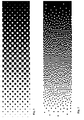
- Figure 1 shows a degrade rendered with AM screening.
- frequency modulation screening the distance between the fixed sized halftone dots is modulated to render different tone values.
- Figure 2 shows the same degrade as in Figure 1, but rendered with FM screening.
- Frequency modulation is sometimes called "stochastic screening", because most FM screening algorithms produce halftone dot patterns that are stochastic (non-deterministic) in nature.
- the continuous tone pixel values P have a range from 0.0 (full black) to 1.0 (full white).
- a modified pixel value Pi of the unscreened image is compared with a fixed threshold T. If Pi is smaller than T, Hi is set to 0.0 and a black pixel is printed, else Hi is made equal to 1.0 and a white pixel is defined.
- the binarization of Pi introduces a quantization error Ei equal to Pi-Hi. According to the error diffusion scheme, this quantization error value is added to one or more of the unscreened pixels Pi+x,j+y, thereby generating a modified pixel value for Pi+x,j+y. Different pixels receive different fractions of the original error and this is controlled by means of "diffusion weights" c1 to cn. The sum of the diffusion weights always adds up to one. Because this scheme acts like a feedback loop, the average quantization error value converges to zero in steady state.
- Robert Ulichney describes a number of enhancements over the original error diffusion algorithm in US 4,955,065. This patent describes the use of a serpentine scan to process the input pixel values, the addition of noise on the threshold and the perturbation of the error diffusion weights to obtain more a uniform and isotropic halftone dot distribution.
- His algorithm consists of a vector error diffusion scheme in which the quantization of a colour into a set of inks is constrained by the output from an additional pre-processing step in such a way that luminance variations - and correspondingly halftoning graininess - are minimised in the final output.
- US 5,565,994 by Eschbach proposes a method that aims for a similar objective but works differently.
- the recording apparatus includes
- the most widely used CtP system in the graphic world is a system makes use of a laser recorder for making a printing master.
- a laser recorder for making a printing master.
- an infrared laser system exposes microdots corresponding to pixels on the printing plate precursor. Small spots are irradiated on the plate wherein the radiation induces chemical or structural changes within the printing plate precursor and after imaging and processing (depending upon the type of printing plate) a ready to use printing master is obtained.
- the dots that are imaged on the printing plate precursor can have different sizes.
- a CtP system writes microdots having a constant size.
- the dot size usually is in de range of 7 ⁇ m to 20 ⁇ m - depending upon the application.
- Ctp Another property of a Ctp system is the addressability. This indicates the precision by which a microdot can be positioned on the plate and is usually expressed in the number of pixels/mm or pixels/inch. All possible locations where a dot can be placed form a square (or sometimes rectangular) grid. In laser recorders, small dots are placed within the grid to form the image to be reproduced.
- the grid can have a resolution up to 2400dpi (e.g. in the AGFA Xcalibur thermal platesetter). This corresponds to an addressable pixel size of about 10 ⁇ m.
- the shape and size of a laser spot in a recording system are usually designed so that the microdots can completely fill the addressable grid with, however, a minimum of overlap. Micro dot size and the size of an addressable pixel therefore are closely related to each other.
- FIG. 6 An example of such a system and the elements in it is shown in Fig. 6.
- the printing plate precursor 4 in this example is mounted on a rotating drum 5 and an inkjet printing head 6 mounted aside the drum 5 jets ink or a reactive fluid onto the printing plate precursor 4 while the drum 5 rotates.
- the inkjet printhead 6 slowly traverses the length of the drum 5and a complete image is recorded pixel by pixel, line by line.
- the inkjet printhead 6 has several nozzles 7 to jet ink so that multiple lines 8 can be recorded during a single rotation.
- the inkjet printhead 6 consists of a plurality of separate tiny chambers containing ink coupled to an ink supply and each having a nozzle 7 at the end.
- thermal inkjet technology tiny resistors rapidly heat a thin layer of liquid ink.
- the heated ink causes a vapour bubble to be formed, expelling or ejecting drops of ink through the nozzles 7 and placing them precisely on a surface to form text or images.
- thermal inkjet technology water-based inks are used.
- Piezoelectric inkjet technology pumps ink through nozzles 7 using pressure like in a squirt gun.
- a piezoelectric crystal is used to drive a very precise pump that ejects ink onto a printing medium.
- a wide range of ink formulations including solvent and water based and UV-curable) are compatible with the piezoelectric inkjet process.
- plate properties are locally influenced by chemical reaction or a printing master is formed by the properties of the image-wise applied ink itself.
- a printing master is formed by the properties of the image-wise applied ink itself.
- the drop jetted to the printing plate precursor has an effect on only a limited area of the plate.
- a droplet volume of 3 picoliter that is printed on an receiving layer in aluminium normally results in a dot having a diameter of 20-30 ⁇ m.
- the resulting size of the dot on the plate is mainly affected by the surface tension effects between the liquid and the aluminium substrate.
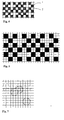
- FIG. 7 A example of a recording grid and printed dots in inkjet printing is shown in Fig. 7.
- a first problem of the original error diffusion as published by Floyd and Steinberg, is that it does not behave well around the tone value of 1/2 and tone values that are multiples of 1/4 and 1/3. At and around these tone values, the standard error diffusion algorithm produces halftone dot distributions that are highly phase correlated, i.e. the dot distributions tend to be organized in locally regular, self-repeating patterns.
- Phase correlated dot positions may introduce low frequency graininess or patterns in color printing
- a consequence of correlated dot positions within a single separation is that it indirectly leads to phase correlation of the dot positions in the different ink separations in the case of color printing. This may introduce low frequency artifacts such as patterns and noise. Moreover, these artifacts shift and change unpredictably in the presence of misregistration between the separations.
- the existing art uses the introduction of a random element such as the perturbation of weights or the addition of noise to the threshold in error diffusion to break up the phase correlated dot positions, but this - as was mentioned before - also introduces graininess in the halftoned image.
- the graininess that is visible in images rendered with frequency modulation halftoning techniques is highly related to the power distribution in the two dimensional Fourier spectrum. Because the human visual system acts as a low pass filter, it is the presence of energy in the lower frequency part of the spectrum that is mostly responsible for the graininess. By filtering the power spectrum of digital halftone with the "contrast sensitivity function'' of the human visual system, a measure is obtained for the amount of visible graininess. With color printing the situation becomes more complicated, as there are not one but three sensitivity functions that have to be considered, each one corresponding with one of the three sensors of the human visual system. Two articles are worth mentioning in that regard: a first one is on "The visibility of patterns in halftone images" by Huw C.
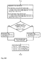
- Figure 12 illustrates a possible workflow in colour printing systems.
- Each input colour pixel is thus represented by a combination of output colour pixels.
- output colour pixels As described above due to the halftoning process an exact match of the colour and brightness is not always possible. Due to the error diffusion process, deviations are distributed to the surrounding pixels as the error in the error diffusion process. Certain combinations of output colour pixels may however lead to unstable reproduction of the image input pixel which can give differences in overall brightness and or colour.
- the overall brightness is especially guarded. Certain output colour pixel combinations are avoided.
- the Brightness B (N 1 -1-l 1 )+(N 2 -1-l 2 )+...+(N k -1-l k ).
- the printing masters are preferably planographic printing masters. These can be made using an inkjet printing system wherein the printed inkjet dots generate hydrophobic and hydrophilic areas on the printing master precursor.
- the planographic printing system normally is a printing system having only two possible intensity levels, but when using e.g. light cyan and /or light magenta ink, the number of intensity levels N for magenta and/or cyan can be considered as to be more than two i.e. no ink, light magenta, full magenta. The same consideration can be made when using light cyan or gray ink when reproducing an image.
- Another aspect is however that a problem remains in halftoning due tot the size of the printed inkjet dots which is larger than the pixel size. Preferably this has also to be taken into account. This can be done in the step wherein from the subset of intensity level combinations one combination is chosen.
- this is done by combining the constrain correlation method with a sub-dot phase modulation error diffusion algorithm which has the advantage that the characteristics of the ideal frequency modulation technique are approximated by making use of the high addressability of the recording system that is not infinite but that is substantially higher that the size of the halftone dots in the inkjet printing system.
- a frequency modulation halftoning system is obtained that offers advantages in suppressing artifacts near rational tonal values.
- sub-dot phase modulation Since with sub-dot phase modulation the position of the halftone dots is controlled with a precision that exceeds the size of the halftone dot, the relative distance between the halftone dots can also be controlled with much greater accuracy than in standard frequency modulation.
- a printing method having the specific features is able to modulate the distance between the halftone dots by taking into account the effect of density value changes caused in an area in the output image by placement of the large inkjet dot.
- the combination of the constraint correlation method with a sub-dot phase modulation method in inkjet printing has the advantage that the error diffusion algorithm can be adjusted in function of the properties of the recording system.
- the processing of a pixel comprises:
- the output pixel values of the halftoned image are all preset to 0.5.
- the error diffusion process consists of replacing the preset values of H(x,y) by either 0.0 or 1.0 in a way that an optimal halftone rendering is obtained of the original image.
- the processing of an image normally is performed line by line, starting at the top of the image. Within a line, the processing takes place from left to right, or from right to left, or - preferably - alternating between these two directions as suggested by Robert Ulichney in US 4,955,065. The latter approach is called "serpentine scan".
- the modification of the error diffusion scheme for choosing one of the combinations of the subset according to our invention consists of:
- nxm processed pixels corresponding to the halftone inkjet dot is determined.
- the phase (or position) of the halftone dots is controlled at the full resolution of the recording device.
- the processing of an image consists of processing the image line-by-line and pixel-by-pixel.
- the ordering of the pixel processing within a line can be from left to right, from right to left or - preferably - according to a serpentine scan.
- One distinguishing characteristic of the new method is that during the "quantization step" at a position (i,j) not just the value of pixel H(i,j) can be altered, but rather the values of a cluster of adjacent pixels H(x,y) around the position (i,j). Such a cluster can consist of the pixels influenced by the placed inkjet dot.
- a quantization set containing the quantization values of the two alternatives - placing a cluster of dark or of light pixels - are evaluated, taking into account density value change upon an area of the inkjet dot corresponding to more than one pixel in the output image and the overlap of the dot with clusters of pixels that were placed by printing a dot in a prior image-processing step.
- the one alternative quantization that most closely approximates the modified pixel value P'(i,j) is selected, the appropriate quantization error is calculated, taking into account inkjet dot overlap, and this error value is distributed to at least one other input pixel.
- the cluster of black pixels is determined by the placement of the halftone dot.
- the alternative choice is normally the definition of a single white pixel, i.e. the cluster has only a single pixel, however the algorithm can indude the definition of plural white pixels.
- a first observation is that the new method of error diffusion adapts for the generation of halftone inkjet dots that are substantially larger than one pixel of the addressable grid of the recording device.
- the position of the halftone inkjet dots in the new method are controlled by an increment that is substantially smaller than the size of the halftone inkjet dots, it allows for the halftone dots to be placed at any arbitrary position of the pixel grid.
- the improved control over the phase of the halftone dots enables to achieve our objective to suppress the spatial rounding off effects that otherwise are the cause of disturbing artifacts near rational tone values - and this without the injection of noise into the algorithm.
- the black cluster of pixels is assumed to be a 3x3 cluster defined by the minimum halftone inkjet dot and they can overprint each other or white space, while the white "clusters" consist of only one pixel and can never overprint a black pixel.
- the inkjet printing system transferring the halftoned colour separated images to the printing masters has certain characteristics
- Fig 13A this means that when placing the smallest dot on the recording grid, an area of about 9 pixels is covered by the ink. This is the case when placing a dot D1 on position p1 shown on the left. Thus placing a single dot at a location within this system causes a density change over a larger area. Normally an area of 9 pixels will be covered. When however, as shown on the right the dot D2 at position p2 overlaps with a pre-existing dot Dp, the influence on the surroundings will be smaller as less dots change from grey to black.
- Fig 13B indicates that not placing a dot has no influence on the surroundings and is only important for the grid location concerned.
- this method enables the exact control of the position of halftone dots consisting of a plurality of pixels on the pixel grid.
- the dots can be placed at any arbitrary position of the pixel grid to optimally represent the input image to be converted. Density value changes of an area in the output image are taken into account.
- the light and dark inks will be printed using different printing plates, but the decisions to print a light or dark halftone dot are to be considered at the same time. For each pixel processed there are three possibilities.
- Inkjet systems are usually capable to print more than one dot size. Therefore for each processed input pixel it is possible to make the decision to :
- Shadowborder and HighlightBorder could be used for the BorderToneValues. More generally stated, the cluster size covered by the inkjet halftone dot can be adjusted depending upon the input pixel value. Possible quantisation levels are restricted based upon input pixel value.
- the size of the halftone dot can alter between two sizes of n by m pixels or q by p, with q>n and p>m.
- the pixel serving as gravity center is put into the dot location map.
- the processing of a halftone dot at the pixel position (i,j) consists of the following steps:
- the transition from one halftone dot size to another one does not occur at a fixed tonal value, but rather is spread out over a range of tonal values.
- This effect is for example obtained by determining the decision of the halftone dot size on the sum of P(i,j) and a small random number. The addition of a random number causes the transition from one dot size to another to occur randomly at a slightly higher or lower tonal values, yielding the desired effect of spreading out the transition from one halftone dot size to another one over a range of tonal values.
- the above embodiment can also be used to render solid text and line art with a cluster size of one pixel, so that their contours are rendered at full resolution. This can be done by setting the output value of the pixel to the corresponding minimum or maximum output value if the input pixel value is the minimum or maximum possible input value.
- Yet another variation of the above embodiment uses halftone dots consisting of fewer pixels for the rendering of image areas containing a high degree of local contrast, such as textures or object boundaries than for image areas containing a low degree of local contrast.
- an unmodified pixel is categorized as belonging to an area containing low local contrast, medium local contrast or high local contrast.
- a large medium or small halftone dot size is produced.
- Categorizing the amount of local contrast is based on measuring the variation of unmodified pixel values in an area around the unmodified pixel P(i,j).
- a simplified approach simply uses the difference between the smallest and largest unmodified pixel value in the area around an unmodified pixel P(i,j). More sophisticated methods that rely on an analysis of the histogram of local neighborhoods are possible to quantify the degree of local contrast and to control the local halftone dot size.
- the constraint correlation method can thus be combined with the different sub-dot phase modulation methods to obtain a optimal halftone reproduction with minimum graininess and luminance variations.
Landscapes
- Engineering & Computer Science (AREA)
- Multimedia (AREA)
- Signal Processing (AREA)
- Facsimile Image Signal Circuits (AREA)
- Ink Jet (AREA)
- Manufacture Or Reproduction Of Printing Formes (AREA)
- Image Processing (AREA)
Abstract
Description
More specifically the invention is related to making printing plates for colour printing by using an inkjet printing system.
- Offset printing using ink repellent and ink attracting areas on the printing master,
- Flexography using compressible relief printing plates,
- Gravure printing,
- Silk screen printing, etc..
In a standard printing process, however, only two levels are possible corresponding to the presence of either ink or no ink. In what is called "multilevel printing systems" more than two printing grey levels are possible (for example five or seventeen), but usually this number is still not sufficient to enable the continuous tone rendering of images.
In the halftoning module the continuous-tone input image that contains a full range of tones from white through intermediate to full tone, is converted into an output image having output pixels wherein only those grey levels are present that are printable.
In the binary halftoning of black and white images, the output values correspond to either black or white, and likewise the result of binary halftoning in colour printing is either full colour or no colour.
In multilevel halftoning the continuous-tone image is converted to an image with pixels having a value out of at least 3 different levels. The pixel may be white, black or can have an intermediate grey value. Besides no ink deposition in printing, multiple levels of ink can be placed on a pixel.
Each halftone dot is reproduced as a microdot or as a clustered set of microdots. A microdot is the smallest element that can be written by a reproduction device.
When the halftone dots are small enough, the eye is not capable of seeing the individual halftone dots, and only sees the corresponding spatially integrated density value of the geometric distribution.
The two main classes of halftoning techniques that are used are known as "amplitude modulation screening" (abbreviated as AM screening) and ''frequency modulation screening" (abbreviated as FM screening).
According to frequency modulation screening, the distance between the fixed sized halftone dots is modulated to render different tone values. Figure 2 shows the same degrade as in Figure 1, but rendered with FM screening. Frequency modulation is sometimes called "stochastic screening", because most FM screening algorithms produce halftone dot patterns that are stochastic (non-deterministic) in nature.
- A first method relies on comparing an image on a pixel-by-pixel basis with a threshold function to obtain FM-screened images. Methods to obtain such a threshold function are described in the patents US 5,535,020, US 5,745,259, US 5,912,745 and US 6,172,773 by Robert Ulichney and in the patents US 5,543,941, US 5,708,518 and US 5,726,772 by Theophano Mitsa and Kevin Parker.
- Lawrence Ray and James Sullivan explain a second method in WO91/12686. According to this method, continuous tone images are directly converted into frequency modulation halftones by addressing in a tone dependent way pre-calculated bitmaps that are stored in a memory.
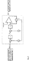
- A third method for frequency modulation was originally invented by Floyd and Steinberg and is called error diffusion. Figure 3 explains how it works.
When multicolour printing is used, each colour component needs to be processed by the halftoning algorithm.
Usually an infrared laser system exposes microdots corresponding to pixels on the printing plate precursor. Small spots are irradiated on the plate wherein the radiation induces chemical or structural changes within the printing plate precursor and after imaging and processing (depending upon the type of printing plate) a ready to use printing master is obtained.
- Infrared laser emitting at 1.06µm with a scan speed of 17m/s, spot size of 10µm and energy in the plane of 248mJ/cm2. Dwell time of the laser spot can be determined at 0.7µs.
- Infrared laser emitting at 1.06µm with a scan speed of 2.2m/s, spot size of 10µm and an energy in the plane of 248mJ/cm2. Dwell time of the laser spot can be determined at 4.8µs.
In laser recorders, small dots are placed within the grid to form the image to be reproduced. The grid can have a resolution up to 2400dpi (e.g. in the AGFA Xcalibur thermal platesetter). This corresponds to an addressable pixel size of about 10µm.
The
The inkjet printhead 6 consists of a plurality of separate tiny chambers containing ink coupled to an ink supply and each having a
Piezoelectric inkjet technology pumps ink through
Some examples can be found in
- There is no need for processing of the printing plate with a special developer after the image is jetted onto the plate. An aqueous developer is all that is needed. No extra chemical for development of the image is needed resulting in a more ecological production method. This allows for easy and inexpensive fabrication of printing plates.
- No special dark room conditions are needed. This results in shorter production times and also opens up the possibility for on-press imaging.
Further advantages and embodiments of the present invention will become apparent from the following description and drawings.
- Fig. 1
- shows a degrade represented by halftoning using AM screening.
- Fig. 2
- shows a degrade represented by halftoning using FM screening
- Fig. 3
- gives the basic working diagram of error diffusion halftoning.
- Fig. 4
- shows the correspondence of dot size and grid resolution in standard FM halftoning.
- Fig. 5
- illustrates the use of pixel replication to obtain larger dots.
- Fig. 6
- depicts an inkjet recorder with the different components.
- Fig. 7
- illustrates the relation of recording grid and printed dots in inkjet recording.
- Fig. 8
- gives an example of a tone value of 128/255 rendered by means of Floyd and Steinberg error diffusion.
- Fig. 9
- shows the rendering of a 192/255 tonal value using the Floyd and Steinberg process.
- Fig. 10
- gives the rendering of a 128/256 tonal value using the improved method according to Ulichney.
- Fig. 11A
- gives the rendering of a value of 128/256 for the cyan ink
- Fig. 11 B
- gives the rendering of a value of 128/256 for the magenta ink
- Fig. 11 C
- shows the result of the overprint of 11A and 11 B in perfect register.
- Fig. 11 D
- shows the result of the overprint of 11A and 11 B having register defects.
- Fig. 12
- shows the workflow in a 4 colour computer to plate system using inkjet printing systems to make the printing masters.
- Fig. 13
- depicts a sub-hypercube of a three colour system containing 23 points
- Fig. 14A
- shows a less conventional description of the standard error diffusion process.
- Fig. 14B
- shows a less conventional description of the error diffusion process according to the invention.
- the information of the input colour image is given by four continuous tone colour separations. These contain the input pixel values of the spatially corresponding component pixels of the different colour separations and represent an input colour pixel of the input colour image.
- by using the halftoning algorithm in the raster image processor (RIP) for each printing colour a halftone image is obtained.
- each halftone representation is transferred to a printing plate precursor by an inkjet printer to obtain a set of four printing masters.
- the final image is reproduced using the four printing masters on a printing press.
Certain combinations of output colour pixels may however lead to unstable reproduction of the image input pixel which can give differences in overall brightness and or colour.
Interactions between different colours is kept under control.
For this printing process with k primaries l1,...,lk, having N1,...,Nk intensity levels respectively, an embodiment according to the present invention can be described as follows.
- The input image is determined by the input colour component values.
- A scalar value is determined wherein the scalar value is at least a function of one of said input pixel values of said spatially corresponding component pixels;
The Brightness B=(N1-1-l1)+(N2-1-l2)+...+(Nk-1-lk).
- The scalar value B is quantized using a multilevel halftoning process. The number of quantization levels for B is preferably M=1+(N1-1)+(N2-1)+...+(Nk-1) but will generally be situated in the range k- N1 +N2+...+Nk. Even more preferably the allowed quantized B-value for an output pixel is restricted to be the one just above or below or on the original B-value of the input pixel. A separate error diffusion process applied to the B-value is an M-level error diffusion process, operating independently from the colour error diffusion. The outcome of the Brightness-error diffusion is used to guide the colour-error diffusion
- This guiding is done by selecting a set of intensity-level combinations which is a subset of the complete set of all possible intensity-level combinations. For B=i, 0≤ i ≤ (N1-1)+(N2-1)+...+(Nk-1), the level set Bi contains all possible combinations yielding B = i.
- To reduce the number of computations as well as to improve the quality of the halftoning, the quantization colour of an output pixel is restricted by an extra output colour restriction to be one of the colours situated on the comers of the sub-hypercube in which the original colour of the input pixel is situated. Each k-dimensional sub-hypercube contains 2k points. A representation of such a sub-hypercube for a three colour system is given in Fig. 13
- The intersection of this set of 2k points with the set of points having a B-level equal to the quantized B-level that is obtained in the B-error diffusion process is non-void. The quantization colour is preferably determined to be the point in this intersection that is closest to the modified pixel colour in the k-dimensional colour space. The modified pixel colour is equal to the original input pixel colour + colour errors received from previously processed pixels. The error to be diffused is the difference between the modified pixel colour and the quantized pixel colour. This difference is calculated in each of the colour channels separately.
- computing for any colour pixel a scalar value which is a function of at least one of said input pixel values of said spatially corresponding component pixels;
- quantizing said scalar value by a multilevel halftoning process to obtain for said colour pixel a quantized scalar value;
- using said quantized scalar value to select, out of all said intensity level combinations, a subset of intensity level combinations;
- selecting one combination out of said subset;
- using said selected combination for creating K printing masters by :
- providing K printing master precursors,
- selectively creating ink carrying and non-ink carrying areas on said printing master precursors according to the selected combination by means of an inkjet printing system. printing inkjet dots on the printing master precursor.
By allowing the distance between the halftone dots to be modulated in much smaller increments than the size of the halftone dots themselves, a frequency modulation halftoning system is obtained that offers advantages in suppressing artifacts near rational tonal values. We call this principle "sub-dot phase modulation". Since with sub-dot phase modulation the position of the halftone dots is controlled with a precision that exceeds the size of the halftone dot, the relative distance between the halftone dots can also be controlled with much greater accuracy than in standard frequency modulation.
A method for converting an image consisting of unprocessed input pixels having n1 possible values representing optical densities into an output image represented by processed pixels having n2 possible values representing optical densities, where 1 <n2<
- a quantization step in which the value of a processed pixel is determined from the value of a modified pixel;
- an error value calculation step in which the difference between the modified and the processed pixel is determined;
- an error diffusion step in which at least one unprocessed pixel is modified by at least a portion of the quantization error value.
- the origin (0,0) of the image corresponds with the top left corner, that
- the value 0.0 represents "black", while 1.0 represents "white".
- Placing a halftone dot means printing a black spot on a white canvas.
- P(x,y) as the input pixels or input pixel value of the original image,
- P'(x,y) as the modified pixels of the original image modified with a contribution of the error made on previous processed pixels obtaining a modified pixel value, and
- H(x,y) as the pixels of the halftoned output image. The error diffusion process will transform every input pixel P(x,y) into a halftone output pixel H(x,y).
- a quantization step in which the value of the pixels forming a cluster, covered by the inkjet dot, are determined from the value of a modified pixel .
- an error calculation step in which the difference between the modified and the processed pixels is determined;
- an error diffusion step in which at least one unprocessed pixel is modified by at least a portion of the quantization error value.
Even in case that the dot positions would tend to be phase correlated, this correlation can be broken up with the introduction of a smaller amount of randomness into the algorithm than without sub-dot phase modulation.
- The resolution of the grid on which the halftone dots can be placed is 110 pixels/mm (2750 pixels/inch)
- the volume of the small droplets deposited on the printing plate precursor are about 4pl resulting in a dot size of 30µm diameter.
Fig 13B indicates that not placing a dot has no influence on the surroundings and is only important for the grid location concerned.
- print a large halftone dot.
- print a small halftone dot
- not to print a halftone dot.
- Range1: (0.0,FirstBorderToneValue]
- Range2: [FirstBorderToneValue, SecondBorderToneValue]
- Range3: [SecondBorderToneValue,1.0]
More generally stated, the cluster size covered by the inkjet halftone dot can be adjusted depending upon the input pixel value. Possible quantisation levels are restricted based upon input pixel value.
Claims (11)
- . A method for creating K printing masters for reproducing an electronic image having colour pixels, each colour pixel being represented by K spatially corresponding component pixels, K > 1, each component pixel having an input pixel value, the printing masters being capable of rendering Nj intensity levels for a component pixel, 1 ≤ j ≤ K, thereby defining N1 * N2 *.. * NK intensity level combinations, the method comprising the steps of :computing for any colour pixel a scalar value which is a function of at least one of said input pixel values of said spatially corresponding component pixels;quantizing said scalar value by a multilevel halftoning process to obtain for said colour pixel a quantized scalar value;using said quantized scalar value to select, out of all said intensity level combinations, a subset of intensity level combinations;selecting one combination out of said subset;using said selected combination for creating K printing masters by :providing K printing master precursors,selectively creating ink-carrying and non ink-carrying areas on said printing master precursors according to the selected combination by means of an inkjet printing system printing dots on the printing master precursors.
- The method according to claim 1 wherein the printing masters are planographic printing plates and wherein the printed inkjet dots generate hydrophobic and hydrophilic areas.
- The method according to claim 1 or 2 wherein said scalar value represents brightness or amount of ink allocation.
- The method according to any one of the preceding claims wherein said scalar value is a linear combination of said input pixel values of at least two of said K colour components.
- The method according to any one of the preceding claims wherein the selection of one combination out of said subset is done using a sub-dot phase modulation error diffusion algorithm causing the position of the inkjet dots to be controlled with an increment that is less than the size of the smallest inkjet dot.
- The method according to claim 5 wherein the position of the inkjet dots can be controlled according to the pixel grid generated by the addressability of the inkjet printing system and the area of the smallest inkjet dot correspond to the area of 3x3 pixels of the pixel grid.
- The method according to claim 5 or 6 wherein the error diffusion algorithm comprises a imprint function dynamically influencing the threshold values in the error diffusion algorithm.
- The method according to any one of the preceding claims wherein the inkjet printing system is a multilevel inkjet printing system.
- The method according to claim 8 wherein the inkjet printing system uses at least two different dot sizes.
- An inkjet printing master made by the method according to any of the preceding claims.
- An system for creating K printing masters for reproducing an electronic image having colour pixels, each colour pixel being represented by K spatially corresponding component pixels, K > 1, each component pixel having an input pixel value, the printing masters being capable of rendering Nj intensity levels for a component pixel, 1 ≤j≤ K, thereby defining N1 * N2 *.. * NK intensity level combinations, the system comprising :means for computing for any colour pixel a scalar value which is a function of at least one of said input pixel values of said spatially corresponding component pixels;means for quantizing said scalar value by a multilevel halftoning process to obtain for said colour pixel a quantized scalar value;selections means for using said quantized scalar value to select, out of all said intensity level combinations, a subset of intensity level combinations;means for selecting one combination out of said subset;means for using said selected combination for creating K printing masters having :means for providing K printing master precursors,an inkjet printing system for selectively creating ink-carrying and non ink-carrying areas on said printing master precursors according to the selected combination by printing dots on the printing master precursors thereby obtaining said printing masters.
Priority Applications (3)
| Application Number | Priority Date | Filing Date | Title |
|---|---|---|---|
| EP03103376A EP1406433A3 (en) | 2002-09-17 | 2003-09-12 | Constraint correlation for computer to plate inkjet system |
| JP2003323623A JP2004262230A (en) | 2002-09-17 | 2003-09-16 | Constraint correlation for computer to plate inkjet system |
| US10/667,250 US7342685B2 (en) | 2002-09-17 | 2003-09-17 | Constraint correlation for computer to plate inkjet system |
Applications Claiming Priority (3)
| Application Number | Priority Date | Filing Date | Title |
|---|---|---|---|
| EP02102364A EP1401189A1 (en) | 2002-09-17 | 2002-09-17 | FM screening with sub-dot phase modulation |
| EP02102364 | 2002-09-17 | ||
| EP03103376A EP1406433A3 (en) | 2002-09-17 | 2003-09-12 | Constraint correlation for computer to plate inkjet system |
Publications (2)
| Publication Number | Publication Date |
|---|---|
| EP1406433A2 true EP1406433A2 (en) | 2004-04-07 |
| EP1406433A3 EP1406433A3 (en) | 2007-05-23 |
Family
ID=31995535
Family Applications (1)
| Application Number | Title | Priority Date | Filing Date |
|---|---|---|---|
| EP03103376A Withdrawn EP1406433A3 (en) | 2002-09-17 | 2003-09-12 | Constraint correlation for computer to plate inkjet system |
Country Status (3)
| Country | Link |
|---|---|
| US (1) | US7342685B2 (en) |
| EP (1) | EP1406433A3 (en) |
| JP (1) | JP2004262230A (en) |
Cited By (1)
| Publication number | Priority date | Publication date | Assignee | Title |
|---|---|---|---|---|
| EP2400322A1 (en) * | 2005-03-14 | 2011-12-28 | Dai Nippon Printing Co., Ltd. | Image display body and image formation method |
Families Citing this family (12)
| Publication number | Priority date | Publication date | Assignee | Title |
|---|---|---|---|---|
| JP2006241435A (en) * | 2005-02-04 | 2006-09-14 | Fuji Photo Film Co Ltd | Ink composition, inkjet recording method, printed article, method for producing planographic printing plate and planographic printing plate |
| US7468814B2 (en) * | 2005-02-08 | 2008-12-23 | Astro-Med, Inc. | Algorithm for controlling half toning process |
| US20090109456A1 (en) * | 2007-10-31 | 2009-04-30 | Seiko Epson Corporation | Image Forming Apparatus, Image Forming Method, and Computer Readable Medium Recording a Printing Data Generation Program |
| US20090109507A1 (en) * | 2007-10-31 | 2009-04-30 | Seiko Epson Corporation | Image Forming Apparatus, Image Forming Method, and Computer Readable Medium Recording a Printing Data Generation Program |
| JP5500831B2 (en) * | 2008-01-25 | 2014-05-21 | 富士フイルム株式会社 | Method for preparing relief printing plate and printing plate precursor for laser engraving |
| US8062720B1 (en) | 2008-05-27 | 2011-11-22 | Vim Technologies Ltd | Printing members for direct imaging and methods of producing same |
| EP2254000A3 (en) * | 2009-05-22 | 2012-05-16 | Ricoh Company, Ltd. | Image forming apparatus with image color measuring unit and image forming method |
| US20110120333A1 (en) * | 2009-11-23 | 2011-05-26 | Michael Karp | Direct inkjet imaging lithographic plates and methods for imaging the plates |
| US9421751B2 (en) | 2009-11-23 | 2016-08-23 | Vim-Technologies Ltd | Direct inkjet imaging lithographic plates, methods for imaging and pre-press treatment |
| US9734440B2 (en) | 2014-01-29 | 2017-08-15 | Rampage Llc | Raster image processor with printhead profile compensation for a multi level digital printing machine |
| US10031458B2 (en) | 2014-09-26 | 2018-07-24 | Hp Indigo B.V. | Reduce merging of adjacent printing dots on a photosensitive member |
| US10051153B1 (en) * | 2017-02-01 | 2018-08-14 | Hp Indigo B.V. | Generating halftones |
Family Cites Families (7)
| Publication number | Priority date | Publication date | Assignee | Title |
|---|---|---|---|---|
| US4680645A (en) * | 1986-08-25 | 1987-07-14 | Hewlett-Packard Company | Method for rendering gray scale images with variable dot sizes |
| US5278671A (en) * | 1990-10-05 | 1994-01-11 | Nippon Steel Corporation | Image processing apparatus with correction of diffusion errors of overlapping dots |
| US5535019A (en) * | 1994-09-15 | 1996-07-09 | Xerox Corporation | Error diffusion halftoning with homogeneous response in high/low intensity image regions |
| US6691618B2 (en) * | 2000-05-08 | 2004-02-17 | Pisces-Print Imaging Sciences, Inc. | Chemical imaging of a lithographic printing plate |
| DE60135729D1 (en) * | 2001-03-09 | 2008-10-23 | Agfa Graphics Nv | Improved halftone color generation for multi-ink printing |
| US6637851B2 (en) * | 2001-03-09 | 2003-10-28 | Agfa-Gevaert | Color halftoning for printing with multiple inks |
| US6962400B2 (en) * | 2002-09-17 | 2005-11-08 | Agfa Gevaert N.V. | Sub-dot phase modulation for computer to plate inkjet system |
-
2003
- 2003-09-12 EP EP03103376A patent/EP1406433A3/en not_active Withdrawn
- 2003-09-16 JP JP2003323623A patent/JP2004262230A/en not_active Abandoned
- 2003-09-17 US US10/667,250 patent/US7342685B2/en not_active Expired - Fee Related
Cited By (1)
| Publication number | Priority date | Publication date | Assignee | Title |
|---|---|---|---|---|
| EP2400322A1 (en) * | 2005-03-14 | 2011-12-28 | Dai Nippon Printing Co., Ltd. | Image display body and image formation method |
Also Published As
| Publication number | Publication date |
|---|---|
| JP2004262230A (en) | 2004-09-24 |
| US20040119994A1 (en) | 2004-06-24 |
| EP1406433A3 (en) | 2007-05-23 |
| US7342685B2 (en) | 2008-03-11 |
Similar Documents
| Publication | Publication Date | Title |
|---|---|---|
| US6962400B2 (en) | Sub-dot phase modulation for computer to plate inkjet system | |
| US7513589B2 (en) | Multipass printing | |
| EP1300000B1 (en) | Halftone dot placement for multi-color images | |
| EP0772347B1 (en) | Colour printing using a dither cell | |
| US20080123148A1 (en) | Reduction of uneven print density | |
| JP3885310B2 (en) | Halftone image generation apparatus and method for reducing defects in printed images | |
| US7342685B2 (en) | Constraint correlation for computer to plate inkjet system | |
| WO1993022871A1 (en) | Method and system of color halftone reproduction | |
| JP4149269B2 (en) | Error diffusion method and system using intermediate dots | |
| US20080158611A1 (en) | Generation of dither matrix | |
| US8363280B2 (en) | System and method of halftone printing of image spot colors using ranked ordered pairing of colorants and halftone screens | |
| JP2000092323A (en) | Dither processing method for color image | |
| EP1401190B1 (en) | Sub dot phase modulation for computer to plate inkjet system | |
| US7088479B2 (en) | Image processing apparatus for electrophotography and electrophotographic apparatus utilizing the same | |
| US6373594B1 (en) | Color printer halftoning method and apparatus | |
| US7599097B2 (en) | Method and system for designing multilevel halftone screens using spot functions | |
| US7440141B2 (en) | Method for generating a dither mask | |
| US6982814B1 (en) | Image printing devices with AM/FM half-toning with self-determination of dot size and method of implementing same | |
| EP2187616A1 (en) | Image data processing for printing | |
| EP1122943B1 (en) | Continuous tone reproduction using improved ink jet droplet dispersion techniques | |
| US20060279788A1 (en) | Automatic generation of supercell halftoning threshold arrays for high addressability devices | |
| US8237989B2 (en) | Method to improve a halftone by combining halftoning with algorithmic processing | |
| EP1608146B1 (en) | Method for generating a dither mask | |
| US20040136035A1 (en) | Method for generating a screened representation of an image | |
| EP1126390A2 (en) | Simulation program having generic attribute access schema |
Legal Events
| Date | Code | Title | Description |
|---|---|---|---|
| PUAI | Public reference made under article 153(3) epc to a published international application that has entered the european phase |
Free format text: ORIGINAL CODE: 0009012 |
|
| AK | Designated contracting states |
Kind code of ref document: A2 Designated state(s): AT BE BG CH CY CZ DE DK EE ES FI FR GB GR HU IE IT LI LU MC NL PT RO SE SI SK TR |
|
| AX | Request for extension of the european patent |
Extension state: AL LT LV MK |
|
| RAP1 | Party data changed (applicant data changed or rights of an application transferred) |
Owner name: AGFA GRAPHICS N.V. |
|
| PUAL | Search report despatched |
Free format text: ORIGINAL CODE: 0009013 |
|
| AK | Designated contracting states |
Kind code of ref document: A3 Designated state(s): AT BE BG CH CY CZ DE DK EE ES FI FR GB GR HU IE IT LI LU MC NL PT RO SE SI SK TR |
|
| AX | Request for extension of the european patent |
Extension state: AL LT LV MK |
|
| RIC1 | Information provided on ipc code assigned before grant |
Ipc: H04N 1/52 20060101ALI20070417BHEP Ipc: H04N 1/405 20060101AFI20070417BHEP |
|
| 17P | Request for examination filed |
Effective date: 20071123 |
|
| AKX | Designation fees paid |
Designated state(s): DE FR GB |
|
| 17Q | First examination report despatched |
Effective date: 20080129 |
|
| STAA | Information on the status of an ep patent application or granted ep patent |
Free format text: STATUS: THE APPLICATION IS DEEMED TO BE WITHDRAWN |
|
| 18D | Application deemed to be withdrawn |
Effective date: 20080809 |