EP1406277A2 - Rotary switch device - Google Patents
Rotary switch device Download PDFInfo
- Publication number
- EP1406277A2 EP1406277A2 EP03022620A EP03022620A EP1406277A2 EP 1406277 A2 EP1406277 A2 EP 1406277A2 EP 03022620 A EP03022620 A EP 03022620A EP 03022620 A EP03022620 A EP 03022620A EP 1406277 A2 EP1406277 A2 EP 1406277A2
- Authority
- EP
- European Patent Office
- Prior art keywords
- contact
- knob
- movable
- contacts
- fixed
- Prior art date
- Legal status (The legal status is an assumption and is not a legal conclusion. Google has not performed a legal analysis and makes no representation as to the accuracy of the status listed.)
- Granted
Links
Images



Classifications
-
- H—ELECTRICITY
- H01—ELECTRIC ELEMENTS
- H01H—ELECTRIC SWITCHES; RELAYS; SELECTORS; EMERGENCY PROTECTIVE DEVICES
- H01H19/00—Switches operated by an operating part which is rotatable about a longitudinal axis thereof and which is acted upon directly by a solid body external to the switch, e.g. by a hand
- H01H19/54—Switches operated by an operating part which is rotatable about a longitudinal axis thereof and which is acted upon directly by a solid body external to the switch, e.g. by a hand the operating part having at least five or an unspecified number of operative positions
- H01H19/60—Angularly-movable actuating part carrying no contacts
- H01H19/63—Contacts actuated by axial cams
-
- H—ELECTRICITY
- H01—ELECTRIC ELEMENTS
- H01H—ELECTRIC SWITCHES; RELAYS; SELECTORS; EMERGENCY PROTECTIVE DEVICES
- H01H19/00—Switches operated by an operating part which is rotatable about a longitudinal axis thereof and which is acted upon directly by a solid body external to the switch, e.g. by a hand
- H01H19/54—Switches operated by an operating part which is rotatable about a longitudinal axis thereof and which is acted upon directly by a solid body external to the switch, e.g. by a hand the operating part having at least five or an unspecified number of operative positions
- H01H19/60—Angularly-movable actuating part carrying no contacts
- H01H19/635—Contacts actuated by rectilinearly-movable member linked to operating part, e.g. by pin and slot
- H01H19/6355—Contacts actuated by rectilinearly-movable member linked to operating part, e.g. by pin and slot using axial cam devices for transforming the angular movement into linear movement along the axis of rotation
Definitions
- the present invention relates to a rotary switch device in which a structure of contacting a movable contact with a fixed contact and separating the movable contact from the fixed contact is improved.
- a rotary switch device shown in Fig. 8.
- This rotary switch device is composed as follows.
- the gear 2 is meshed with a gear 3.
- a holder support 4 is attached to this gear 3, and a contact holder 5 is attached to this holder support 4.
- Movable contacts 6 are attached to the contact holder 5.
- Fixed contacts 7 to 9 corresponding to the movable contacts 6 are provided on a base plate 10.
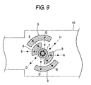
- Fig. 9 is a view showing an arrangement of the fixed contacts 7 to 9 on the base plate 10 in detail.
- black points show the contacting points at which the movable contacts 6 come into contact with the fixed contacts 7 to 9.
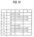
- the movable contact 6 comes into contact with the fixed contacts 7 and 8, so that the fixed contacts 7 and 8 can be connected with each other.
- the operation state B the movable contact 6 comes into contact with the fixed contacts 7, 8 and 9, so that the fixed contacts 7, 8 and 9 can be connected with each other.
- the operation state C the movable contact 6 comes into contact with the fixed contacts 7 and 9, so that the fixed contacts 7 and 9 can be connected with each other.
- the movable contact 6 comes into contact with only the fixed contact 7, that is, the movable contact 6 does not come into contact with the other fixed contacts 8 and 9.
- Fig. 10 is a table on which the above operation is shown.
- this structure has the following disadvantages.
- the accuracy of switching is greatly affected by the accuracy of meshing of the gear 2 with the gear 3 and the positional deviation of the movable contact 6. Therefore, the actual thing must be manufactured with considerably high accuracy. Unless the actual thing is manufactured with considerably high accuracy, the reliability of the product is lowered.
- the present invention has been accomplished in view of the above circumstances. It is an object of the present invention to provide a rotary switch device, the reliability with respect to the switching accuracy of which is high even when the actual thing is not manufactured with considerably high accuracy.
- the present invention provides a rotary switch device comprising: a knob to be rotated for operation; a wave-shaped guide portion provided in the knob in the rotary direction; a plurality of contact holders provided in the guide portion so that they can be individually, linearly reciprocated being moved in accordance with the rotation of the knob; a plurality of movable contacts respectively provided in the contact holders; and a plurality of fixed contact which are contacted with and separated from these movable contacts, wherein a different state of connection of the movable contacts with the fixed contacts is successively realized by a linear reciprocating motion of the plurality of individual contact holders according to the rotation of the knob.
- the knob is operated by rotation, all movable contacts are linearly reciprocated.
- the fixed contacts are linearly arranged. Therefore, the sufficiently large fixed contacts can be arranged even in a limited space. Accordingly, it is possible to extend an operation stroke of each movable contact. There is no possibility that the switching accuracy is greatly affected by the assembling accuracy of the other parts and the positional deviation of the movable contacts. Consequently, it is unnecessary to manufacture the actual thing with considerably high accuracy. Therefore, high reliability can be provided.
- reference numeral 11 is an operation lever, for example, arranged in a portion close to a steering wheel of a vehicle. Various parts shown in Fig. 1 are incorporated into the operation lever 11.
- reference numeral 12 is a knob, which is formed into a short cylinder having a lid.
- One guide piece 13 is incorporated into the knob 12.
- This one guide piece 13 is formed into a short cylinder, the diameter of which is smaller than that of the knob 12, and provided with an internal cylinder 14 inside.
- This internal cylinder 14 has a wave-shaped portion 15 on the side opposite to the inner side of the knob 12 (on the right in the drawing). Each wave-form of the wave-form portion 15 is trapezoidal.
- this one guide piece 13 may be integrally formed with the knob 12.
- reference numeral 16 is the other guide piece which forms a pair together with one guide piece 13 described above.
- the other guide piece 16 is formed into a ring-shape and provided with a wave-shaped portion 17 on the guide piece 13 side.
- Shape of the wave-shaped portion 17 is constituted by a plurality of trapezoids.
- This other guide piece 16 is incorporated into one guide piece 13.
- the wave-shaped portion 17 is opposed to the wave-shaped portion 15.
- a gap formed between the wave-shaped portion 17 and the wave-shaped portion 15 forms a guide portion 18 composed of a wave-shaped groove.
- Reference numerals 19 and 20 are contact holders. Both contact holders 19 and 20 respectively have protrusions 21 and 22, which are inserted into the aforementioned guide portion 18. On the sides of the contact holders 19 and 20 opposite to the side on which the protrusions 21 and 22 are arranged, the movable contacts 23 and 24 are attached. At the forward end portions of these movable contacts 23 and 24, there are provided contacts 23a, 23b, 24a, 24b shown in Figs. 3 to 6. Although not shown in the drawing, traverse movements of these contact holds 19, 20 are restricted by some structure arranged in the operation lever 11.
- Reference numeral 25 is a base plate. On the lower face of this base plate 25, there are provided fixed contacts 26, 27, 28. These fixed contacts 26, 27, 28 correspond to the movable contacts 23, 24. In these fixed contacts, the fixed contact 26 is formed into a crank-shape. On the other hand, both the fixed contacts 27, 28 are respectively formed into a simple rectangle.
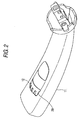
- knob 11 As described before, these parts are incorporated into the operation lever 11, however, as shown in Fig. 2, one portion of the knob 11 is exposed outside from the window portion 29 of the operation lever 11, so that the knob 11 can be rotated by operation.
- Figs. 3 to 6 are views showing the displacement of the movable contacts 23, 24 (the displacement of the contact holders 19, 20) in the order of operation of the knob 12.
- the movable contact 23 makes the contact 23a come into contact with the fixed contact 26.
- the movable contact 23 makes the contact 23b come into contact with the fixed contact 27. Due to this contacting operation, the fixed contacts 26 and 27 are connected with each other.
- the movable contact 24 makes the contact 24a come into contact with the fixed contact 26, however, the contact 24b is not contacted with the fixed contact 28. Therefore, these fixed contacts 26 and 28 are not connected with each other.
- the movable contact 23 makes the contact 23a come into contact with the fixed contact 26 and also makes the contact 23b come into contact with the fixed contact 27. Due to this switching operation, these fixed contacts 26 and 27 are connected with each other.
- the movable contact 24 makes the contact 24a come into contact with the fixed contact 26, and at the same time, the contact 24b is contacted with the fixed contact 28. Therefore, these fixed contacts 26 and 28 are connected with each other.
- the movable contact 23 makes the contact 23a come into contact with the fixed contact 26, however, the movable contact 23 does not make the contact 23b come into contact with the fixed contact 27. Therefore, these fixed contacts 26 and 27 are not connected with each other.
- the movable contact 24 makes the contact 24a come into contact with the fixed contact 26 and also makes the contact 24b come into contact with the fixed contact 28. Due to this switching operation, these fixed contacts 26 and 28 are connected with each other.
- the movable contact 23 makes the contact 23a come into contact with the fixed contact 26, however, the movable contact 23 does not make the contact 23b come into contact with the fixed contact 27. Therefore, these fixed contacts 26 and 27 are not connected with each other.
- the movable contact 24 makes the contact 24a come into contact with the fixed contact 26.
- the movable contact 24 does not make the contact 24b come into contact with the fixed contact 28. Therefore, these fixed contacts 26 and 28 are connected with each other.
- the same operation as that described above is endlessly repeated in the operation stages A to D. This repetition is shown on the table of Fig. 7.
- the knob 12 is operated by rotation, all movable contacts 23, 24 are linearly reciprocated.
- the fixed contacts 26 to 28 are linearly arranged not being swollen. Therefore, the sufficiently large fixed contacts can be arranged even in a limited space (especially, in a space, the width of which is limited) such as a space on the lower face of the base plate 25. Accordingly, it is possible to extend an operation stroke of each movable contact 23, 24. There is no possibility that the switching accuracy is greatly affected by the assembling accuracy of the other parts and the positional deviation of the movable contacts. Consequently, it is unnecessary to manufacture the actual thing with considerably high accuracy. Therefore, high reliability can be provided.
- the present invention is not limited to the above specific embodiment shown in the accompanying drawings. Especially, the present invention may be applied to a case in which the numbers of the movable and the fixed contacts are not less than the aforementioned numbers. Further, the rotary switch device of the invention can be used for not only vehicles but also the other apparatus. Furthermore, the rotary switch device of the invention is not limited to the use of incorporating it into an operation lever. That is, variations may be made without departing from the scope of the invention.
- the rotary switch device of the present invention even when the actual thing is not manufactured with considerably high accuracy, it is possible to provide a rotary switch device, the switching accuracy of which is highly reliable.
Landscapes
- Rotary Switch, Piano Key Switch, And Lever Switch (AREA)
- Slide Switches (AREA)
Abstract
Description
First, in Fig. 2,
When the
After one revolution has been completed, the same operation as that described above is endlessly repeated in the operation stages A to D. This repetition is shown on the table of Fig. 7.
Claims (3)
- A rotary switch device comprising:wherein a different state of connection of the movable contacts with the fixed contacts is successively realized by a linear reciprocating motion of the plurality of individual contact holders according to the rotation of the knob.a knob to be rotated for operation;a wave-shaped guide portion provided in the knob in a rotary direction;a plurality of contact holders provided in the guide portion, which can be individually, linearly reciprocated in accordance with the rotation of the knob;a plurality of movable contacts respectively provided in the contact holders;a plurality of fixed contacts adapted to be in contact with and separated from the movable contacts,
- The rotary switch device according to claim 1, wherein shape of the guide portion is constituted by a plurality of trapezoids.
- The rotary switch device according to claim 1, wherein the contact holder includes a protrusion which is projected from one side thereof and inserted into the guide portion, and the movable contact is attached to the other side of the contact holder.
Applications Claiming Priority (2)
| Application Number | Priority Date | Filing Date | Title |
|---|---|---|---|
| JP2002292376 | 2002-10-04 | ||
| JP2002292376A JP4139182B2 (en) | 2002-10-04 | 2002-10-04 | Rotary switch device |
Publications (3)
| Publication Number | Publication Date |
|---|---|
| EP1406277A2 true EP1406277A2 (en) | 2004-04-07 |
| EP1406277A3 EP1406277A3 (en) | 2006-01-18 |
| EP1406277B1 EP1406277B1 (en) | 2013-12-11 |
Family
ID=31987210
Family Applications (1)
| Application Number | Title | Priority Date | Filing Date |
|---|---|---|---|
| EP03022620.3A Expired - Lifetime EP1406277B1 (en) | 2002-10-04 | 2003-10-06 | Rotary switch device |
Country Status (2)
| Country | Link |
|---|---|
| EP (1) | EP1406277B1 (en) |
| JP (1) | JP4139182B2 (en) |
Cited By (6)
| Publication number | Priority date | Publication date | Assignee | Title |
|---|---|---|---|---|
| CN105914080A (en) * | 2015-02-25 | 2016-08-31 | 株式会社东海理化电机制作所 | Switch device |
| CN106133868A (en) * | 2014-04-03 | 2016-11-16 | 株式会社东海理化电机制作所 | Switching device |
| DE102011005370B4 (en) * | 2010-03-11 | 2017-12-07 | Alps Electric Co., Ltd. | Lever actuator |
| US20180346069A1 (en) * | 2017-06-05 | 2018-12-06 | Shimano Inc. | Bicycle operating device |
| WO2020204734A1 (en) * | 2019-04-04 | 2020-10-08 | Merit Poland Spolka Z Ograniczona Odpowiedzialnoscia | Rotary switch assembly. in particular of a steering wheel column integrated module of an automotive vehicle |
| DE102024102204A1 (en) | 2024-01-25 | 2025-07-31 | Porsche Ebike Performance Gmbh | Signal generator for an electronic component of a bicycle |
Families Citing this family (4)
| Publication number | Priority date | Publication date | Assignee | Title |
|---|---|---|---|---|
| JP4687443B2 (en) * | 2005-12-21 | 2011-05-25 | 株式会社デンソー | Dial operation device |
| JP4579856B2 (en) * | 2006-03-30 | 2010-11-10 | 株式会社東海理化電機製作所 | Rotation operation type output device |
| JP4620636B2 (en) * | 2006-06-22 | 2011-01-26 | 株式会社東海理化電機製作所 | Rotation operation type output device |
| JP2024150232A (en) * | 2023-04-10 | 2024-10-23 | 株式会社東海理化電機製作所 | Switch System |
Family Cites Families (5)
| Publication number | Priority date | Publication date | Assignee | Title |
|---|---|---|---|---|
| FR2403638A1 (en) * | 1977-09-14 | 1979-04-13 | Antivols Simplex Sa | Rotating multicontact switch for vehicle ignition locks - has sprung barrel roller contacts and fixed contacts inside cup-shaped insulating block |
| JP3765550B2 (en) * | 1997-03-21 | 2006-04-12 | アルプス電気株式会社 | In-vehicle knob switch device |
| DE19722780C1 (en) * | 1997-06-02 | 1998-11-12 | Kostal Leopold Gmbh & Co Kg | Electrical rotary switching unit esp. for steering column switch |
| JP2000067702A (en) * | 1998-08-19 | 2000-03-03 | Alps Electric Co Ltd | On-vehicle knob switch device |
| FR2785084B1 (en) * | 1998-10-23 | 2003-01-31 | Sc2N Sa | ELECTRIC SWITCHING DEVICE, ESPECIALLY FOR A MOTOR VEHICLE |
-
2002
- 2002-10-04 JP JP2002292376A patent/JP4139182B2/en not_active Expired - Fee Related
-
2003
- 2003-10-06 EP EP03022620.3A patent/EP1406277B1/en not_active Expired - Lifetime
Cited By (11)
| Publication number | Priority date | Publication date | Assignee | Title |
|---|---|---|---|---|
| DE102011005370B4 (en) * | 2010-03-11 | 2017-12-07 | Alps Electric Co., Ltd. | Lever actuator |
| CN106133868A (en) * | 2014-04-03 | 2016-11-16 | 株式会社东海理化电机制作所 | Switching device |
| EP3128527A4 (en) * | 2014-04-03 | 2017-11-15 | Kabushiki Kaisha Tokai-Rika-Denki-Seisakusho | Switch device |
| CN105914080A (en) * | 2015-02-25 | 2016-08-31 | 株式会社东海理化电机制作所 | Switch device |
| EP3062325A1 (en) * | 2015-02-25 | 2016-08-31 | Kabushiki Kaisha Tokai Rika Denki Seisakusho | Switch device |
| US9721737B2 (en) | 2015-02-25 | 2017-08-01 | Kabushiki Kaisha Tokai Rika Denki Seisakusho | Switch device |
| CN105914080B (en) * | 2015-02-25 | 2018-06-05 | 株式会社东海理化电机制作所 | Switching device |
| US20180346069A1 (en) * | 2017-06-05 | 2018-12-06 | Shimano Inc. | Bicycle operating device |
| US10562585B2 (en) * | 2017-06-05 | 2020-02-18 | Shimano Inc. | Bicycle operating device |
| WO2020204734A1 (en) * | 2019-04-04 | 2020-10-08 | Merit Poland Spolka Z Ograniczona Odpowiedzialnoscia | Rotary switch assembly. in particular of a steering wheel column integrated module of an automotive vehicle |
| DE102024102204A1 (en) | 2024-01-25 | 2025-07-31 | Porsche Ebike Performance Gmbh | Signal generator for an electronic component of a bicycle |
Also Published As
| Publication number | Publication date |
|---|---|
| JP4139182B2 (en) | 2008-08-27 |
| JP2004127808A (en) | 2004-04-22 |
| EP1406277B1 (en) | 2013-12-11 |
| EP1406277A3 (en) | 2006-01-18 |
Similar Documents
| Publication | Publication Date | Title |
|---|---|---|
| US6211474B1 (en) | Multi-input switch | |
| EP1406277B1 (en) | Rotary switch device | |
| JP2000099242A (en) | Key switch | |
| EP1146530A1 (en) | Multidirectional input device | |
| EP2752865B1 (en) | Push switch | |
| US6069327A (en) | Switch device | |
| US6034338A (en) | Lever switch arrangement used for vehicles | |
| KR101423145B1 (en) | Multi-operation switch device | |
| JPH11277462A (en) | Switch mechanism for power tool | |
| KR101622501B1 (en) | Switch | |
| JP2007035402A (en) | Operation mechanism of electric device | |
| JP3054817U (en) | Jog switch | |
| JPH08167344A (en) | Microswitch | |
| JPS5915368Y2 (en) | push button switch | |
| JPH0416328Y2 (en) | ||
| JP2515060Y2 (en) | Changeover switch | |
| JPS58895Y2 (en) | Slide switch | |
| JP3133890B2 (en) | Switch device | |
| GB1570845A (en) | Lever-operated electric switch | |
| JP2007207563A (en) | Electric device operation mechanism | |
| JPS5927029Y2 (en) | jack | |
| JPH0515406U (en) | Slide operation type electric parts | |
| JPS6346807Y2 (en) | ||
| JPH0323634Y2 (en) | ||
| JP6160347B2 (en) | switch |
Legal Events
| Date | Code | Title | Description |
|---|---|---|---|
| PUAI | Public reference made under article 153(3) epc to a published international application that has entered the european phase |
Free format text: ORIGINAL CODE: 0009012 |
|
| AK | Designated contracting states |
Kind code of ref document: A2 Designated state(s): AT BE BG CH CY CZ DE DK EE ES FI FR GB GR HU IE IT LI LU MC NL PT RO SE SI SK TR |
|
| AX | Request for extension of the european patent |
Extension state: AL LT LV MK |
|
| PUAL | Search report despatched |
Free format text: ORIGINAL CODE: 0009013 |
|
| AK | Designated contracting states |
Kind code of ref document: A3 Designated state(s): AT BE BG CH CY CZ DE DK EE ES FI FR GB GR HU IE IT LI LU MC NL PT RO SE SI SK TR |
|
| AX | Request for extension of the european patent |
Extension state: AL LT LV MK |
|
| 17P | Request for examination filed |
Effective date: 20060222 |
|
| AKX | Designation fees paid |
Designated state(s): DE FR GB SE |
|
| 17Q | First examination report despatched |
Effective date: 20110323 |
|
| GRAP | Despatch of communication of intention to grant a patent |
Free format text: ORIGINAL CODE: EPIDOSNIGR1 |
|
| RIC1 | Information provided on ipc code assigned before grant |
Ipc: H01H 19/635 20060101ALI20130515BHEP Ipc: H01H 19/63 20060101AFI20130515BHEP |
|
| INTG | Intention to grant announced |
Effective date: 20130606 |
|
| GRAS | Grant fee paid |
Free format text: ORIGINAL CODE: EPIDOSNIGR3 |
|
| GRAA | (expected) grant |
Free format text: ORIGINAL CODE: 0009210 |
|
| AK | Designated contracting states |
Kind code of ref document: B1 Designated state(s): DE FR GB SE |
|
| REG | Reference to a national code |
Ref country code: GB Ref legal event code: FG4D |
|
| REG | Reference to a national code |
Ref country code: DE Ref legal event code: R096 Ref document number: 60345414 Country of ref document: DE Effective date: 20140206 |
|
| REG | Reference to a national code |
Ref country code: SE Ref legal event code: TRGR |
|
| REG | Reference to a national code |
Ref country code: DE Ref legal event code: R097 Ref document number: 60345414 Country of ref document: DE |
|
| PLBE | No opposition filed within time limit |
Free format text: ORIGINAL CODE: 0009261 |
|
| STAA | Information on the status of an ep patent application or granted ep patent |
Free format text: STATUS: NO OPPOSITION FILED WITHIN TIME LIMIT |
|
| 26N | No opposition filed |
Effective date: 20140912 |
|
| REG | Reference to a national code |
Ref country code: DE Ref legal event code: R097 Ref document number: 60345414 Country of ref document: DE Effective date: 20140912 |
|
| REG | Reference to a national code |
Ref country code: FR Ref legal event code: PLFP Year of fee payment: 14 |
|
| PGFP | Annual fee paid to national office [announced via postgrant information from national office to epo] |
Ref country code: FR Payment date: 20160919 Year of fee payment: 14 |
|
| PGFP | Annual fee paid to national office [announced via postgrant information from national office to epo] |
Ref country code: DE Payment date: 20160927 Year of fee payment: 14 Ref country code: GB Payment date: 20161005 Year of fee payment: 14 |
|
| PGFP | Annual fee paid to national office [announced via postgrant information from national office to epo] |
Ref country code: SE Payment date: 20161011 Year of fee payment: 14 |
|
| REG | Reference to a national code |
Ref country code: DE Ref legal event code: R119 Ref document number: 60345414 Country of ref document: DE |
|
| REG | Reference to a national code |
Ref country code: SE Ref legal event code: EUG |
|
| GBPC | Gb: european patent ceased through non-payment of renewal fee |
Effective date: 20171006 |
|
| REG | Reference to a national code |
Ref country code: FR Ref legal event code: ST Effective date: 20180629 |
|
| PG25 | Lapsed in a contracting state [announced via postgrant information from national office to epo] |
Ref country code: GB Free format text: LAPSE BECAUSE OF NON-PAYMENT OF DUE FEES Effective date: 20171006 Ref country code: DE Free format text: LAPSE BECAUSE OF NON-PAYMENT OF DUE FEES Effective date: 20180501 |
|
| PG25 | Lapsed in a contracting state [announced via postgrant information from national office to epo] |
Ref country code: FR Free format text: LAPSE BECAUSE OF NON-PAYMENT OF DUE FEES Effective date: 20171031 Ref country code: SE Free format text: LAPSE BECAUSE OF NON-PAYMENT OF DUE FEES Effective date: 20171007 |