EP1406276A1 - METAL DOME SHEET, ITS MANUFACTURING METHOD, AND METAL DOME SYSTEM - Google Patents
METAL DOME SHEET, ITS MANUFACTURING METHOD, AND METAL DOME SYSTEM Download PDFInfo
- Publication number
- EP1406276A1 EP1406276A1 EP02733386A EP02733386A EP1406276A1 EP 1406276 A1 EP1406276 A1 EP 1406276A1 EP 02733386 A EP02733386 A EP 02733386A EP 02733386 A EP02733386 A EP 02733386A EP 1406276 A1 EP1406276 A1 EP 1406276A1
- Authority
- EP
- European Patent Office
- Prior art keywords
- adhesive layer
- metal
- metal dome
- domes
- metal domes
- Prior art date
- Legal status (The legal status is an assumption and is not a legal conclusion. Google has not performed a legal analysis and makes no representation as to the accuracy of the status listed.)
- Granted
Links
Images




Classifications
-
- H—ELECTRICITY
- H01—ELECTRIC ELEMENTS
- H01H—ELECTRIC SWITCHES; RELAYS; SELECTORS; EMERGENCY PROTECTIVE DEVICES
- H01H11/00—Apparatus or processes specially adapted for the manufacture of electric switches
-
- H—ELECTRICITY
- H01—ELECTRIC ELEMENTS
- H01H—ELECTRIC SWITCHES; RELAYS; SELECTORS; EMERGENCY PROTECTIVE DEVICES
- H01H13/00—Switches having rectilinearly-movable operating part or parts adapted for pushing or pulling in one direction only, e.g. push-button switch
- H01H13/70—Switches having rectilinearly-movable operating part or parts adapted for pushing or pulling in one direction only, e.g. push-button switch having a plurality of operating members associated with different sets of contacts, e.g. keyboard
- H01H13/7006—Switches having rectilinearly-movable operating part or parts adapted for pushing or pulling in one direction only, e.g. push-button switch having a plurality of operating members associated with different sets of contacts, e.g. keyboard comprising a separate movable contact element for each switch site, all other elements being integrated in layers
-
- H—ELECTRICITY
- H01—ELECTRIC ELEMENTS
- H01H—ELECTRIC SWITCHES; RELAYS; SELECTORS; EMERGENCY PROTECTIVE DEVICES
- H01H13/00—Switches having rectilinearly-movable operating part or parts adapted for pushing or pulling in one direction only, e.g. push-button switch
- H01H13/70—Switches having rectilinearly-movable operating part or parts adapted for pushing or pulling in one direction only, e.g. push-button switch having a plurality of operating members associated with different sets of contacts, e.g. keyboard
- H01H13/702—Switches having rectilinearly-movable operating part or parts adapted for pushing or pulling in one direction only, e.g. push-button switch having a plurality of operating members associated with different sets of contacts, e.g. keyboard with contacts carried by or formed from layers in a multilayer structure, e.g. membrane switches
-
- H—ELECTRICITY
- H01—ELECTRIC ELEMENTS
- H01H—ELECTRIC SWITCHES; RELAYS; SELECTORS; EMERGENCY PROTECTIVE DEVICES
- H01H2203/00—Form of contacts
- H01H2203/02—Interspersed fingers
-
- H—ELECTRICITY
- H01—ELECTRIC ELEMENTS
- H01H—ELECTRIC SWITCHES; RELAYS; SELECTORS; EMERGENCY PROTECTIVE DEVICES
- H01H2203/00—Form of contacts
- H01H2203/036—Form of contacts to solve particular problems
- H01H2203/038—Form of contacts to solve particular problems to be bridged by a dome shaped contact
-
- H—ELECTRICITY
- H01—ELECTRIC ELEMENTS
- H01H—ELECTRIC SWITCHES; RELAYS; SELECTORS; EMERGENCY PROTECTIVE DEVICES
- H01H2205/00—Movable contacts
- H01H2205/016—Separate bridge contact
-
- H—ELECTRICITY
- H01—ELECTRIC ELEMENTS
- H01H—ELECTRIC SWITCHES; RELAYS; SELECTORS; EMERGENCY PROTECTIVE DEVICES
- H01H2205/00—Movable contacts
- H01H2205/016—Separate bridge contact
- H01H2205/024—Means to facilitate positioning
- H01H2205/026—Adhesive sheet
-
- H—ELECTRICITY
- H01—ELECTRIC ELEMENTS
- H01H—ELECTRIC SWITCHES; RELAYS; SELECTORS; EMERGENCY PROTECTIVE DEVICES
- H01H2213/00—Venting
- H01H2213/016—Venting in adhesive layer
-
- H—ELECTRICITY
- H01—ELECTRIC ELEMENTS
- H01H—ELECTRIC SWITCHES; RELAYS; SELECTORS; EMERGENCY PROTECTIVE DEVICES
- H01H2221/00—Actuators
- H01H2221/002—Actuators integral with membrane
-
- H—ELECTRICITY
- H01—ELECTRIC ELEMENTS
- H01H—ELECTRIC SWITCHES; RELAYS; SELECTORS; EMERGENCY PROTECTIVE DEVICES
- H01H2223/00—Casings
- H01H2223/002—Casings sealed
- H01H2223/003—Membrane embracing all keys
Definitions
- the present invention relates to metal dome sheets for low-profile operating switch panels for use in electric and electronic instruments such as mobile telephones, methods of fabricating the metal dome sheets and metal dome systems.
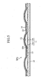
- low-profile operating switch panels having structures as shown in FIG. 1 and FIG. 5.
- a plurality of metal domes 12 to be disposed at electrodes 11 on a substrate 10 are fixed with a film 14 adhered to the substrate 10 via an adhesive layer 13.
- the metal dome 12 is usually made of an elastic hemispheric cap of metal. Moreover, as shown in FIG. 2 for example, the metal dome 12 is disposed on an electrode 11 including a pair of an arc electrode layer 11a and a straight electrode layer 11b guided therein (a thickness of this layer is made slightly lower than the electrode layer 11a, or an insulating layer is provided thereon).
- the metal dome 12 In a free state as shown in FIG. 3, if a user presses the metal dome 12 from above the film, then the cap is crushed down and a switch is turned on as shown in FIG. 4. When a finger is released, the cap restitutes and the switch is turned off.
- a plurality of metal domes 12 to be disposed at electrodes 11 on a substrate 10 are fitted into relevant holes 15a on a spacer film 15 and fixed with a film 14 adhered to the spacer film 15 via an adhesive layer 13.
- each of the metal domes 12 constitutes an independent sealed space in the switch panel SP 1 in FIG. 1, air escape holes (not shown) communicating with the inside of the dome are provided on the adhesive layer 13 and on the film 14, or alternatively, such an air escape hole is provided on the substrate 10, where the air inside the dome is set open to outside air.
- the spacer film 15 can be simply placed on the substrate 10. Then, upon pressing the metal dome 12, the air compressed inside the dome is dispersed temporarily in the periphery thereof through gaps under the spacer film 15. Therefore, the switch panel SP 2 has an advantage that provision of an air escape hole is not particularly required, and so forth.
- the present invention is made in consideration of the foregoing problems.
- a metal dome sheet according to the present invention basically has a structure similar to that shown in FIG. 1, in which an adhesive layer removed portion is provided at an adhesive layer portion between at least two adjacent metal domes so as to constitute an air escape portion.
- an adhesive layer removed portion is provided at an adhesive layer portion between at least two adjacent metal domes so as to constitute an air escape portion.
- only part of the metal dome such as an upper portion thereof is adhered and fixed with an adhesive layer; meanwhile, a peripheral portion of a disposed region of each metal dome is hermetically sealed, whereby air inside the dome can be evacuated easily and penetration of humidity or dust in the outside air can be prevented.
- a fabricating method thereof is designed such that the air escape portion or a partial adhesive layer is fabricated easily and with high accuracy upon formation of the adhesive layer, by a printing process used in the process technology for printed boards or the like.
- a first aspect of the present invention provides a metal dome sheet to be hermetically adhered to a plurality of metal domes disposed at electrodes on a substrate and adhered to other portions of the substrate except portions where the metal domes are disposed via an adhesive layer.
- the metal dome sheet includes an adhesive layer removed portion being provided in an adhesive layer portion between at least two pieces of the metal domes adjacent to each other so as to constitute an air escape portion.
- a second aspect of the present invention provides a method of fabricating the metal dome sheet according to the first aspect, in which the adhesive layer removed portion is formed as an adhesive layer unprinted portion upon formation of the adhesive layer portion by a printing process.
- a third aspect of the present invention provides a metal dome sheet to be covered on a plurality of metal domes disposed at electrodes on a substrate and covered on other portions of the substrate except portions where the metal domes are disposed via an adhesive layer.
- the metal dome sheet includes an adhesive layer provided on an upper face of each of the metal domes for fixing the metal dome, and a peripheral portion in a disposed region of each of the metal domes is hermetically sealed.
- a fourth aspect of the present invention provides a method of fabricating the metal dome sheet according to the third aspect, in which the adhesive layer on the upper face of each of the metal domes is formed by a printing process.
- a fifth aspect of the present invention provides a metal dome system including a substrate, a plurality of metal domes disposed at electrodes on the substrate, an adhesive layer for covering the metal domes, and a metal dome sheet for covering the adhesive layer, in which an air escape communicating passage is provided between at least two pieces of the metal domes adjacent to each other.
- a sixth aspect of the present invention provides a method of fabricating the metal dome system according to the fifth aspect, in which the air escape communicating passage is formed as an adhesive layer unprinted portion upon formation of the adhesive layer by a printing process.
- FIG. 7 shows one example of a low-profile operating switch panel adopting a metal dome sheet according to the present invention.
- this switch panel SP 3 has almost the same structure as the switch panel SP 1 shown in FIG. 1.
- a constitution of an adhesive layer 23 to be formed on one side of a metal dome sheet 24A is largely different from the relevant constitution in the switch panel SP 1 .
- a substrate 10, electrodes 11 and metal domes 12 of FIG. 7 severally have the same structures as those in FIG. 1.
- the metal dome sheet 24A of the present invention is made of a film such as a polyethylene telephthalate.
- an adhesive layer removed portion 23a is provided on part of the adhesive layer 23 between at least two adjacent metal domes 12 to constitute a sort of a passage, and such a passage is defined as an air escape portion (passage) ⁇ .
- the user can enjoy comfortable operation feeling by this air escape portions ⁇ . Moreover, since large loads (stress) on the periphery are reduced by provision of the air escape portions ⁇ , separation of adhered portions are suppressed, for example. In addition, a good damage prevention effect on the switch panel SP 3 itself is also obtained.
- each of the air escape portions ⁇ is designed basically as an independent sealed space. In other words, the air escape portion ⁇ is communicated only with the metal domes 12.
- the air escape portion ⁇ does not include any portions made open to outside air. Accordingly, if penetration of humidity or dust in the outside air is avoided upon assembly, the air escape portion ⁇ can maintain such a state stably. In other words, it is possible to obtain an excellent switch panel which does not incur deterioration with time.
- this switch panel SP 3 upon fabrication of this switch panel SP 3 , although modes for forming the adhesive layer removed portions 23a as well as the adhesive layer 23 on one side of the metal dome sheet 24A as shown in FIG. 9 are not particularly limited, a printing process used in the process technology for printed boards or the like is suitable.
- the adhesive layer removed portions 23a easily in accurate shapes.
- High accuracy in the adhesive layer removed portions 23a also means high accuracy in the adhesive layer 23. Accordingly, the respective metal domes 12 can be adhered by mutually equal adhesive power without unevenness. In other words, it is possible to obtain a high-quality switch without unevenness in operation feeling.
- FIG. 10 shows another example of a low-profile operating switch panel adopting a metal dome sheet according to the present invention.
- this switch panel SP 4 also has almost the same structure as the switch panel SP 1 shown in FIG. 1.
- a constitution of an adhesive layer 23 to be formed on one side of a metal dome sheet 24B is largely different from the relevant constitution in the switch panel SP 1 .
- a substrate 10, electrodes 11 and metal domes 12 of FIG. 10 severally have the same structures as those in FIG. 1.
- the metal dome sheet 24B of the present invention is also made of a film such as a polyethylene telephthalate.
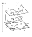
- circular adhesive layers 23 are provided on upper faces of the metal domes 12, near tops thereof, for example, whereby respective metal domes 12 are fixed.
- an adhesive layer 23 is also provided in the periphery of a disposed region of the metal domes 12 and such an adhesive layer 23 is adhered to the substrate 10.
- portions without the adhesive layers 23 collectively constitute a sort of a wide air escape portion (passage) ⁇ 0 .
- the disposed region of the respective metal domes 12 is hermetically sealed by adhesion of the periphery portion with adhesive layer 23a.
- shapes of the adhesive layers 23 on the near tops of the metal domes 12 are not limited to circular shapes, but cross shapes, simple straight band shapes, radial shapes and the like may be also acceptable.
- sizes of the above-mentioned various forms of adhesive layers 23 including those in circular shapes will be decided as appropriate in consideration of retention force against the metal domes 12, which are subjected to frequent pressing operations.
- the user can enjoy more comfortable operation feeling by this air escape portions ⁇ 0 .
- large loads (stress) on the periphery are reduced by provision of the air escape portions ⁇ 0 , separation of adhered portions are suppressed, for example.
- a good damage prevention effect on the switch panel SP 4 itself is also obtained.
- this metal dome sheet 24B is hermitically sealed and there are no portions made open to outside air. Accordingly, if penetration of humidity or dust in the outside air is avoided upon assembly, the air escape portion ⁇ can maintain such a state stably. In other words, it is possible to obtain an excellent switch panel which does not incur deterioration with time.
- this switch panel SP 4 upon fabrication of this switch panel SP 4 , although modes for forming the adhesive layers 23 partially on one side of the metal dome sheet 24B as shown in FIG. 12 are not particularly limited, a printing process used in the process technology for printed boards or the like is suitable.
- the adhesive layers 23 easily in accurate shapes.
- the respective metal domes 12 can be adhered by mutually equal adhesive power without unevenness. In other words, it is possible to obtain a high-quality switch without unevenness in operation feeling.
- the metal dome sheet of the present invention it is possible to obtain a low-profile operating switch panel with less thickness and less weight owing to reduction in the number of components, which is also excellent in water resistance and dust resistance.
- the method of fabricating the metal dome sheet of the present invention formation of the adhesive layers is carried out by a printing process used in the process technology for printed boards or the like. Accordingly, it is possible to form the adhesive layers easily and in high accuracy. Therefore, the respective metal domes can be adhered by mutually equal adhesive power without unevenness. As a result, it is possible to obtain a high-quality switch without unevenness in operation feeling.
Landscapes
- Engineering & Computer Science (AREA)
- Manufacturing & Machinery (AREA)
- Push-Button Switches (AREA)
- Manufacture Of Switches (AREA)
Abstract
Description
Moreover, as shown in FIG. 11 and FIG. 12, circular
Claims (6)
- A metal dome sheet being hermetically adhered to a plurality of metal domes disposed at electrodes on a substrate and adhered to other portions of the substrate except portions where the metal domes are disposed via an adhesive layer, the metal dome sheet comprising:an adhesive layer removed portion being provided in an adhesive layer portion between at least two pieces of the metal domes adjacent to each other so as to constitute an air escape portion.
- A method of fabricating the metal dome sheet according to claim 1, comprising the step of:forming the adhesive layer removed portion as an adhesive layer unprinted portion upon formation of the adhesive layer portion by a printing process.
- A metal dome sheet being covered on a plurality of metal domes disposed at electrodes on a substrate and covered on other portions of the substrate except portions where the metal domes are disposed via an adhesive layer, the metal dome sheet comprising:wherein a peripheral portion in a disposed region of each of the metal domes is hermetically sealed.an adhesive layer provided on an upper face of each of the metal domes for fixing the metal dome,
- A method of fabricating the metal dome sheet according claim 3, comprising the step of:forming the adhesive layer on the upper face of each of the metal domes by a printing process.
- A metal dome system provided with a substrate, a plurality of metal domes disposed at electrodes on the substrate, an adhesive layer for covering the metal domes, and a metal dome sheet for covering the adhesive layer, the metal dome system comprising:an air escape communicating passage being provided between at least two pieces of the metal domes adjacent to each other.
- A method of fabricating the metal dome system according to claim 5, comprising the step of:forming the air escape communicating passage as an adhesive layer unprinted portion upon formation of the adhesive layer by a printing process.
Applications Claiming Priority (3)
| Application Number | Priority Date | Filing Date | Title |
|---|---|---|---|
| JP2001173264A JP4417588B2 (en) | 2001-06-07 | 2001-06-07 | Metal dome sheet |
| JP2001173264 | 2001-06-07 | ||
| PCT/JP2002/005653 WO2002101776A1 (en) | 2001-06-07 | 2002-06-07 | Metal dome sheet, its manufacturing method, and metal dome system |
Publications (3)
| Publication Number | Publication Date |
|---|---|
| EP1406276A1 true EP1406276A1 (en) | 2004-04-07 |
| EP1406276A4 EP1406276A4 (en) | 2005-03-09 |
| EP1406276B1 EP1406276B1 (en) | 2011-08-03 |
Family
ID=19014755
Family Applications (1)
| Application Number | Title | Priority Date | Filing Date |
|---|---|---|---|
| EP02733386A Expired - Lifetime EP1406276B1 (en) | 2001-06-07 | 2002-06-07 | Metal dome sheet, its manufacturing method, and metal dome system |
Country Status (8)
| Country | Link |
|---|---|
| US (1) | US6917007B2 (en) |
| EP (1) | EP1406276B1 (en) |
| JP (1) | JP4417588B2 (en) |
| KR (1) | KR100574001B1 (en) |
| CN (1) | CN100446143C (en) |
| DK (1) | DK1406276T3 (en) |
| TW (1) | TW591679B (en) |
| WO (1) | WO2002101776A1 (en) |
Cited By (4)
| Publication number | Priority date | Publication date | Assignee | Title |
|---|---|---|---|---|
| DE102004058482A9 (en) * | 2003-12-05 | 2006-12-21 | Citizen Electronics Co., Ltd., Fujiyoshida | Key area element module |
| EP2284853A1 (en) * | 2009-08-11 | 2011-02-16 | CoActive Technologies, Inc. | Electrical switch comprising a force transmission element fixed between a film and a snap disc |
| EP2362404A1 (en) * | 2010-02-26 | 2011-08-31 | Research In Motion Limited | Keypad assembly |
| US8274005B2 (en) | 2010-02-26 | 2012-09-25 | Research In Motion Limited | Keypad assembly |
Families Citing this family (22)
| Publication number | Priority date | Publication date | Assignee | Title |
|---|---|---|---|---|
| DE10258209A1 (en) * | 2002-12-12 | 2004-06-24 | Siemens Ag | Module with input device for mobile telephone incorporates flexible carrier with cap mounted in frame and includes mechanically- stable fixing member |
| JP2005209616A (en) | 2003-12-25 | 2005-08-04 | Alps Electric Co Ltd | Sheet with movable contact and push button switch using the same |
| JPWO2005124805A1 (en) * | 2004-06-15 | 2008-04-17 | 日本航空電子工業株式会社 | Dome contact and multistage electric switch using the same |
| JP4317806B2 (en) * | 2004-10-19 | 2009-08-19 | アルプス電気株式会社 | Contact structure |
| JP2006164870A (en) * | 2004-12-10 | 2006-06-22 | Matsushita Electric Ind Co Ltd | Movable contact body and panel switch configured using the same |
| US7687137B2 (en) | 2005-02-28 | 2010-03-30 | Kyocera Corporation | Insulating substrate and manufacturing method therefor, and multilayer wiring board and manufacturing method therefor |
| JP2006294429A (en) * | 2005-04-12 | 2006-10-26 | Matsushita Electric Ind Co Ltd | Movable contact body and panel switch configured using the same |
| TWM302108U (en) * | 2006-04-10 | 2006-12-01 | Hon Hai Prec Ind Co Ltd | Switch with a dome sheet |
| US7378609B1 (en) | 2006-05-10 | 2008-05-27 | John Fedorjaka | Metal dome switch assembly with enhanced snap ratio |
| JP2008016310A (en) * | 2006-07-06 | 2008-01-24 | Matsushita Electric Ind Co Ltd | Movable contact body |
| KR100844945B1 (en) | 2006-12-14 | 2008-07-09 | 주)두성하이텍 | Conductive tape attached to dome sheet of mobile terminal and its manufacturing method |
| US8089009B2 (en) * | 2007-10-30 | 2012-01-03 | Zippy Technology Corp. | Annular multi-instruction switch |
| JP5060922B2 (en) * | 2007-11-19 | 2012-10-31 | アルプス電気株式会社 | Seat with movable contact and switch device |
| JP2009193905A (en) * | 2008-02-18 | 2009-08-27 | Panasonic Corp | Panel switch |
| US7687735B2 (en) * | 2008-05-30 | 2010-03-30 | Sipix Technology Inc. | Packaging structure for depression switches |
| US8089017B2 (en) * | 2008-10-07 | 2012-01-03 | Research In Motion Limited | Sealed dome switch for mobile electronic device |
| US9810401B2 (en) * | 2013-11-21 | 2017-11-07 | Ford Global Technologies, Llc | Luminescent trim light assembly |
| CN104797075B (en) * | 2014-01-17 | 2019-02-26 | 中兴通讯股份有限公司 | Arched PCB and its design method |
| JP6424353B2 (en) * | 2014-03-07 | 2018-11-21 | マグマカンパニーリミテッド | Tact switch |
| CN103915275A (en) * | 2014-03-26 | 2014-07-09 | 海门市曼博莱电子发展有限公司 | Waterproof thin film switch |
| US10128062B2 (en) * | 2015-12-31 | 2018-11-13 | Eaton Intelligent Power Limited | Strain gauge proportional push button |
| CN108597931A (en) * | 2018-07-09 | 2018-09-28 | 东莞市聚明电子科技有限公司 | A button structure and button module capable of reducing noise when pressing buttons |
Family Cites Families (16)
| Publication number | Priority date | Publication date | Assignee | Title |
|---|---|---|---|---|
| US4689879A (en) * | 1985-01-14 | 1987-09-01 | Robertshaw Controls Company | Method of making a membrane keyboard |
| JPH0438437Y2 (en) * | 1988-05-26 | 1992-09-09 | ||
| JP2844736B2 (en) * | 1989-10-25 | 1999-01-06 | 松下電器産業株式会社 | Panel stitch and manufacturing method thereof |
| JP3988203B2 (en) * | 1996-10-22 | 2007-10-10 | 松下電器産業株式会社 | Movable contact for panel switch |
| FR2762134B1 (en) * | 1997-04-11 | 1999-06-18 | Nicomatic | SUB-ASSEMBLY AND METHOD FOR MANUFACTURING DEVICES SUCH AS KEYBOARDS |
| JPH11297158A (en) * | 1998-04-10 | 1999-10-29 | Fujikura Ltd | Membrane switch and method of manufacturing the same |
| KR20000071435A (en) * | 1999-03-12 | 2000-11-25 | 가쯔미 야마무라 | Light illuminating type switch |
| JP2001014974A (en) * | 1999-06-29 | 2001-01-19 | Alps Electric Co Ltd | Sheet with movable contact, and sheet switch |
| JP2001014973A (en) * | 1999-06-29 | 2001-01-19 | Alps Electric Co Ltd | Sheet with movable contact, and sheet switch |
| JP2001035305A (en) * | 1999-07-23 | 2001-02-09 | Japan Aviation Electronics Industry Ltd | Air escape structure of dome switch |
| DE60104071T2 (en) * | 2000-04-18 | 2005-08-25 | Mitsumi Electric Co., Ltd. | REED SWITCH |
| JP2002056746A (en) * | 2000-08-07 | 2002-02-22 | Alps Electric Co Ltd | Sheet having movable contact point and sheet switch |
| JP2002056737A (en) * | 2000-08-08 | 2002-02-22 | Seiko Precision Inc | Illumination-type switch |
| JP3931570B2 (en) * | 2001-02-16 | 2007-06-20 | 松下電器産業株式会社 | Manufacturing method of movable contact body |
| JP4187421B2 (en) * | 2001-03-08 | 2008-11-26 | アルプス電気株式会社 | Method for peeling release sheet from sheet with contact plate provided with release sheet and method for manufacturing switch device using the same |
| JP2003141969A (en) * | 2001-10-31 | 2003-05-16 | Mitsumi Electric Co Ltd | switch |
-
2001
- 2001-06-07 JP JP2001173264A patent/JP4417588B2/en not_active Expired - Fee Related
-
2002
- 2002-06-07 DK DK02733386.3T patent/DK1406276T3/en active
- 2002-06-07 US US10/479,743 patent/US6917007B2/en not_active Expired - Fee Related
- 2002-06-07 KR KR1020037015961A patent/KR100574001B1/en not_active Expired - Fee Related
- 2002-06-07 TW TW091112425A patent/TW591679B/en not_active IP Right Cessation
- 2002-06-07 WO PCT/JP2002/005653 patent/WO2002101776A1/en not_active Ceased
- 2002-06-07 EP EP02733386A patent/EP1406276B1/en not_active Expired - Lifetime
- 2002-06-07 CN CNB028115031A patent/CN100446143C/en not_active Expired - Fee Related
Cited By (5)
| Publication number | Priority date | Publication date | Assignee | Title |
|---|---|---|---|---|
| DE102004058482A9 (en) * | 2003-12-05 | 2006-12-21 | Citizen Electronics Co., Ltd., Fujiyoshida | Key area element module |
| DE102004058482B4 (en) * | 2003-12-05 | 2015-08-20 | Citizen Electronics Co., Ltd. | Film panel |
| EP2284853A1 (en) * | 2009-08-11 | 2011-02-16 | CoActive Technologies, Inc. | Electrical switch comprising a force transmission element fixed between a film and a snap disc |
| EP2362404A1 (en) * | 2010-02-26 | 2011-08-31 | Research In Motion Limited | Keypad assembly |
| US8274005B2 (en) | 2010-02-26 | 2012-09-25 | Research In Motion Limited | Keypad assembly |
Also Published As
| Publication number | Publication date |
|---|---|
| WO2002101776A1 (en) | 2002-12-19 |
| TW591679B (en) | 2004-06-11 |
| US6917007B2 (en) | 2005-07-12 |
| KR100574001B1 (en) | 2006-04-25 |
| US20040234072A1 (en) | 2004-11-25 |
| CN1515013A (en) | 2004-07-21 |
| EP1406276B1 (en) | 2011-08-03 |
| EP1406276A4 (en) | 2005-03-09 |
| KR20040004696A (en) | 2004-01-13 |
| JP2002367477A (en) | 2002-12-20 |
| JP4417588B2 (en) | 2010-02-17 |
| DK1406276T3 (en) | 2011-10-31 |
| CN100446143C (en) | 2008-12-24 |
Similar Documents
| Publication | Publication Date | Title |
|---|---|---|
| US6917007B2 (en) | Metal dome sheet, its manufacturing method, and metal dome system | |
| US4463234A (en) | Tactile feel membrane switch assembly | |
| US4508942A (en) | Keyboard switch | |
| US5986228A (en) | Movable contact unit for panel switch and panel switch using the same | |
| JPH06325661A (en) | Film switch | |
| US4456798A (en) | Panel keyboard with irregular surfaced spacer | |
| EP1178508A1 (en) | Assembly for a keypad | |
| WO2006032894A3 (en) | Membrane electrode assembly | |
| US6548779B2 (en) | Sheet having moving contacts and sheet switch | |
| US5218177A (en) | Screened pattern causing gaps around keyboard membrane spacer hole to increase venting and reduced bounce | |
| US7129435B2 (en) | Movable contact element and panel switch using the same | |
| US7619176B2 (en) | Switch and electronic equipment having the same | |
| JP2001035305A (en) | Air escape structure of dome switch | |
| JP2009193905A (en) | Panel switch | |
| US20060225996A1 (en) | Movable contact element and panel switch formed using the same | |
| JP2006139952A (en) | Switching arrangement and component for it | |
| US7301114B2 (en) | Movable contact unit | |
| JP2006173025A (en) | Key input device and method of suppressing operation force of the same | |
| JPH0662433U (en) | Waterproof panel switch unit | |
| US20070062152A1 (en) | Domesheet assembly in a keyboard | |
| KR200368751Y1 (en) | A dome switch mounting structure for mobile-phone | |
| JP2007220528A (en) | Movable contact structure and pushbutton switch | |
| JP4486012B2 (en) | Switch device | |
| JPH08306261A (en) | Surface mount intermittent operation switch and its manufacture | |
| CN100585765C (en) | Switching device with elastic foil |
Legal Events
| Date | Code | Title | Description |
|---|---|---|---|
| PUAI | Public reference made under article 153(3) epc to a published international application that has entered the european phase |
Free format text: ORIGINAL CODE: 0009012 |
|
| 17P | Request for examination filed |
Effective date: 20040105 |
|
| AK | Designated contracting states |
Kind code of ref document: A1 Designated state(s): AT BE CH CY DE DK ES FI FR GB GR IE IT LI LU MC NL PT SE TR |
|
| A4 | Supplementary search report drawn up and despatched |
Effective date: 20050126 |
|
| REG | Reference to a national code |
Ref country code: DE Ref legal event code: 8566 |
|
| 17Q | First examination report despatched |
Effective date: 20091229 |
|
| GRAP | Despatch of communication of intention to grant a patent |
Free format text: ORIGINAL CODE: EPIDOSNIGR1 |
|
| RTI1 | Title (correction) |
Free format text: METAL DOME SHEET, ITS MANUFACTURING METHOD, AND METAL DOME SYSTEM |
|
| GRAS | Grant fee paid |
Free format text: ORIGINAL CODE: EPIDOSNIGR3 |
|
| GRAA | (expected) grant |
Free format text: ORIGINAL CODE: 0009210 |
|
| AK | Designated contracting states |
Kind code of ref document: B1 Designated state(s): DK FI GB |
|
| REG | Reference to a national code |
Ref country code: GB Ref legal event code: FG4D |
|
| REG | Reference to a national code |
Ref country code: DK Ref legal event code: T3 |
|
| PLBE | No opposition filed within time limit |
Free format text: ORIGINAL CODE: 0009261 |
|
| STAA | Information on the status of an ep patent application or granted ep patent |
Free format text: STATUS: NO OPPOSITION FILED WITHIN TIME LIMIT |
|
| 26N | No opposition filed |
Effective date: 20120504 |
|
| PGFP | Annual fee paid to national office [announced via postgrant information from national office to epo] |
Ref country code: DK Payment date: 20120612 Year of fee payment: 11 |
|
| PGFP | Annual fee paid to national office [announced via postgrant information from national office to epo] |
Ref country code: GB Payment date: 20120606 Year of fee payment: 11 Ref country code: FI Payment date: 20120612 Year of fee payment: 11 |
|
| REG | Reference to a national code |
Ref country code: DK Ref legal event code: EBP Effective date: 20130630 |
|
| GBPC | Gb: european patent ceased through non-payment of renewal fee |
Effective date: 20130607 |
|
| PG25 | Lapsed in a contracting state [announced via postgrant information from national office to epo] |
Ref country code: FI Free format text: LAPSE BECAUSE OF NON-PAYMENT OF DUE FEES Effective date: 20130607 |
|
| PG25 | Lapsed in a contracting state [announced via postgrant information from national office to epo] |
Ref country code: GB Free format text: LAPSE BECAUSE OF NON-PAYMENT OF DUE FEES Effective date: 20130607 |
|
| PG25 | Lapsed in a contracting state [announced via postgrant information from national office to epo] |
Ref country code: DK Free format text: LAPSE BECAUSE OF NON-PAYMENT OF DUE FEES Effective date: 20130630 |