EP1406270A2 - Method for manufacturing an electrical cable system comprising an electrical cable containing a conductor and for installing said electrical cable system over a longitudinally expandable-contractible element. - Google Patents
Method for manufacturing an electrical cable system comprising an electrical cable containing a conductor and for installing said electrical cable system over a longitudinally expandable-contractible element. Download PDFInfo
- Publication number
- EP1406270A2 EP1406270A2 EP20030300102 EP03300102A EP1406270A2 EP 1406270 A2 EP1406270 A2 EP 1406270A2 EP 20030300102 EP20030300102 EP 20030300102 EP 03300102 A EP03300102 A EP 03300102A EP 1406270 A2 EP1406270 A2 EP 1406270A2
- Authority
- EP
- European Patent Office
- Prior art keywords
- electrical cable
- cable system
- hose
- clamping
- undulations
- Prior art date
- Legal status (The legal status is an assumption and is not a legal conclusion. Google has not performed a legal analysis and makes no representation as to the accuracy of the status listed.)
- Withdrawn
Links
Images


Classifications
-
- F—MECHANICAL ENGINEERING; LIGHTING; HEATING; WEAPONS; BLASTING
- F16—ENGINEERING ELEMENTS AND UNITS; GENERAL MEASURES FOR PRODUCING AND MAINTAINING EFFECTIVE FUNCTIONING OF MACHINES OR INSTALLATIONS; THERMAL INSULATION IN GENERAL
- F16L—PIPES; JOINTS OR FITTINGS FOR PIPES; SUPPORTS FOR PIPES, CABLES OR PROTECTIVE TUBING; MEANS FOR THERMAL INSULATION IN GENERAL
- F16L53/00—Heating of pipes or pipe systems; Cooling of pipes or pipe systems
- F16L53/30—Heating of pipes or pipe systems
- F16L53/35—Ohmic-resistance heating
- F16L53/37—Ohmic-resistance heating the heating current flowing directly through the pipe to be heated
-
- F—MECHANICAL ENGINEERING; LIGHTING; HEATING; WEAPONS; BLASTING
- F16—ENGINEERING ELEMENTS AND UNITS; GENERAL MEASURES FOR PRODUCING AND MAINTAINING EFFECTIVE FUNCTIONING OF MACHINES OR INSTALLATIONS; THERMAL INSULATION IN GENERAL
- F16L—PIPES; JOINTS OR FITTINGS FOR PIPES; SUPPORTS FOR PIPES, CABLES OR PROTECTIVE TUBING; MEANS FOR THERMAL INSULATION IN GENERAL
- F16L53/00—Heating of pipes or pipe systems; Cooling of pipes or pipe systems
- F16L53/30—Heating of pipes or pipe systems
- F16L53/35—Ohmic-resistance heating
Definitions
- the present invention relates to a method for manufacturing an electrical cable system comprising an electrical cable containing a conductor core and for installing said electrical cable system over a longitudinally expandable-contractible element and also relates to such a manufactured electrical cable system.
- Subsea pipelines are conventionally used for transporting fluid such as gas or oil from a well to a platform/template or the like.
- fluid such as gas or oil
- the pipeline wall is heated by the hot (150 to 200 degrees C) flowing fluid.
- the pipeline wall will during this phase obtain its maximum elongation.
- the heating system comprises a subsea electrical cable clamped to the pipeline surface at more or less regular intervals, in parallel to the pipeline axis.
- the subsea electrical cable is submitted to pulling forces - typically around 20 kN - so that it becomes a tensioned cable.
- the pipeline is quite capable of expanding and contracting - in the axial direction - as a result of temperature changes, - this is not so with the clamped subsea electrical cable. Forced into the same elongation during production, typical tension in the subsea electrical cable will be increased from 20 kN to 120 kN approximately but such a high tension is unpredictable to handle and beyond what is acceptable for the cable itself and the cable clamps. The clamps will therefore break or move relatively to the subsea electrical cable and the pipeline and in worst case damaging both.
- an object of the invention is to provide a method allowing an electrical cable to withstand tension during its manufacturing and during installation on to the outer surface of an longitudinally expandable-contractible element and further preventing the cable to set up high tension when the length of the expandable-contractible element fluctuates.
- the invention provides a method for manufacturing an electrical cable system comprising an electrical cable containing a conductor core and for installing said electrical cable system over a longitudinally expandable-contractible element characterized in that it comprises the successive steps of :
- substantially attached undulations means undulations substantially constant in terms of amplitude, form or length. It is a way to prevent the electrical cable from stretching or elongating during manufacturing, transport and installation. In other words, during manufacturing and installation attached undulations form an additional length as compared to the length of a straight electrical cable.
- the electrical cable of the invention is able to withstand tension during manufacturing and installation, the tension from installation is removed after installation by handling said secondary element. Once said releasing is done, the additional length is converted into a "free to be used" excess length : the electrical cable is able to extend while keeping its wavy form instead of elongating as a straight electrical cable.
- the method according the invention can comprise the step of using a radially expandable hose as said secondary element and the disposing step can consist of stranding said radially expandable hose and said electrical cable together in a helical-like configuration.
- the method according the invention can comprise the step of radially expanding said hose by providing high internal pressure within said hose before said stranding process.
- the method can comprise the step of maintaining said high internal pressure during the clamping process and said handling process can consist of reducing said internal pressure, said hose being radially non expanded.
- the method can comprise the step of providing a common outer sheath surrounding said hose and said electrical cable.
- the present invention provides an electrical cable system comprising an electrical cable containing a conductor core and suitable for being installed by clamping over a longitudinally expandable-contractible element characterized in that it further comprises said secondary element which is disposed over said electrical cable in a way to give said electrical cable substantially attached undulations before and during said clamping, thereby forming an additional length, and in that said secondary element is handleable in order to release the attachment of said undulations after said clamping, thereby converting said additional length in a free to be used excess length .
- said secondary element is a radially expandable hose with an adjustable internal pressure.
- the internal pressure is high during said manufacturing and installation and lower internal pressure after the handling.
- the stranding process ensures the electrical cable as well as the secondary element wavy forms.
- the expandable hose and the electrical cable can be stranded together in a helical-like configuration in order to obtain said attached undulations.
- the electrical cable system can comprise a common outer sheath surrounding said secondary element and said electrical cable.
- said conductor core is a copper core and is covered with a polymer insulation sheath.
- the invention also provides a heating system comprising an electrical cable system as described previously to be clamped at least at two points to a subsea pipeline.
- Figure 1 discloses a partial, perspective and longitudinal view of an electrical cable system 1 according to a preferred embodiment of the invention.
- the electrical cable system 1 comprises :
- the hose 3 is a high pressure hydraulic hose preferably with a synthetic braiding (not shown).
- the inner liner is flexible and the braiding is not tight at one atmosphere.
- the hose 3 When pressurized, the hose 3 is radially expanded, and the synthetic braiding tightened.
- the stranded electrical cable 10 is able to withstand high tension without stretching or elongating.
- the hose 3 While manufacturing said electrical cable system 1, the hose 3 is pressurised, then said hose 3 and the electrical cable 10 are stranded together in a helical-like or spiral-like shape and the common outer sheath 5 is providing.
- this common outer sheath 5 is to protect the electrical cable 10 and the hose 3 during transportation, during installation of the electrical cable system 1 over a subsea pipeline.
- the wavy form of the electrical cable 10 consists of undulations 100 attached by the stranded hose 3, creating an additional length as compared to the length of a straight electrical cable.
- the electrical cable 10 is substantially prevented from moving.
- the dimension of the additional length is set by the lay length and the relation between the diameters of the copper core 2 and the hose 3.
- the polymer insulation sheath 4 preferably comprises an inner semiconductor layer as inner screen, an insulation layer and an outer semiconductor layer as outer screen,
- FIG 2 a heating system which comprises the electrical cable system 1 is schematically illustrated.
- An insulated metal tube 1' i. e. the pipeline
- the tube 1' has an outer thermal insulation ensuring that fluid such as crude oil coming from the template 20 has a sufficiently low viscosity until it reaches platform 50. If the oil flow is stopped, formation of hydrate plugs and wax deposits occur which can block the pipeline when oil transportation is to be resumed again.
- the tube 1' can be heated.
- One or several sections 6 of the tube 1' are connected to a power supply unit 70 installed on the platform 50 with a riser cable 8 containing one or more conductor pairs with an insulated feeder and return conductor.
- the riser cable 8 is protected by an armoring and an outer sheathing.
- connecting elements 11, 12 are proposed respectively to connect the electrical cable system 1 and a single conductor cable 9 to a return conductor and a feeder conductor in the riser cable 8. More over, the electrical cable system 1 and the single conductor cable 9 are connected with the section 6 of tube 1'. Insulating flanges 13, 14 insulate the section(s) 6 of a pipeline from each other.
- the electrical cable system 1 is clamped in parallel to the pipeline axis and at more or less regular intervals in the heated section 6 by a series of clamps 7 and preferably straps.
- the power supply unit 70 generates an electrical AC current, preferably in the range of 500 to 2000 A, and a voltage which is preferably in the range of 5 to 40 KV.
- the current is fed via riser cable 8, the electrical cable of the electrical cable system 1 and the conductor cable 9 through a section 6 of the tube 1.
- the AC current causes a heating of the tube 1' in section 6 and ensures a sufficiently low viscosity of the material inside.
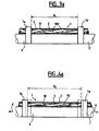
- Fig 3a is a schematic drawing (not in scale) showing partially and in a longitudinal section the electrical cable system 1 during clamping to the subsea pipeline in section 6.
- the electrical cable system 1 extends to both sides from straps 7a and 7b.
- the distance between the two straps is by way of example some six to ten meters.
- the hose 3 and the electrical cable 10 are stranded together in a helical like configuration.
- d 1 is the distance between the two straps 7a and 7b.
- the attached undulations 100 of the electrical cable 10 within the common sheath 5 give obviously the additional length higher to said distance d1.
- the section 6 of the pipeline 1' is cold and has its minimal elongation.
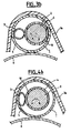
- Figure 3b discloses schematically (not in scale) a cross section of the electrical cable system 1 of figure 3a.
- the pressurised hose 3 has a circular-like cross section.
- the center B of the electrical cable 10 with the copper core 2 and the polymer insulation sheath 4 is shifted from the center A defined by the common protective sheath 5.
- the internal pressure of the hose 3 is removed (step not shown) giving the hose a cross section as illustrated in Fig 4b.
- the hose 3 now is flexible both in radial and longitudinal direction Consequently, the built-in additional length is therefore converted in a "free to be used" excess length since the undulations of the electrical cable 10 are no more attached and the electrical cable may act as a centre element.
- Fig 4a is a schematic drawing (not in scale) showing in a longitudinal section the electrical cable system 1 during hot fluid transportation in the subsea pipeline 1'.
- the depressurised hose 3 is just laid around the electrical cable 10.
- the straps 7a, 7b followed the expansion of the pipeline 1' (symbolized by the arrows X-X') as shown by the dotted lines indicating the position of said straps before the flowing of hot fluid.
- the distance d 2 separating said straps has increased.
- the electrical cable 10 by using a part of the defined excess length has attenuated undulations 110 within the common outer sheath 5. If required, the electrical cable 10 may become a straight electrical cable at the maximal temperature of the subsea pipeline. The excess length is adjusted to extension-contraction of the pipeline 1' caused by the temperature variations.
- the outer sheath 5 is easily expandable at low level of tension thanks to a good elasticity and a relatively low module.
- Fig 4b discloses schematically (not in scale) a cross section of the electrical cable system 1 when the internal pressure in the hose is released, - regardless of whether the pipeline is hot or not.
- the center B of the electrical cable 10 is nearer to the center A of the outer protective sheath 5.
- the depressurised hose 3 has a oval ⁇ like cross section.
- the electrical cable 10 is able to withstand pulling forces of 20 - 30 kN before and during clamping. After depressurisation, the tension from installation is removed.
- the electrical cable 10 extends instead of elongating, without setting up too much force, estimated around 3 kN. Therefore, during length fluctuations of the pipeline, the straps will not support effort and the electrical cable is safe.
Landscapes
- Engineering & Computer Science (AREA)
- General Engineering & Computer Science (AREA)
- Mechanical Engineering (AREA)
- Insulated Conductors (AREA)
- Processes Specially Adapted For Manufacturing Cables (AREA)
- Cable Accessories (AREA)
- Manufacturing Of Electric Cables (AREA)
Abstract
- disposing a secondary element (3) over said electrical cable so as to give said electrical cable substantially attached undulations (100) thereby forming an additional length,
- installing by clamping at least at two points said electrical cable system to said longitudinally expandable-contractible element,
- handling said secondary element after said clamping so as to release the attachment of said undulations thereby converting said additional length into a free to be used excess length.
Description
- The present invention relates to a method for manufacturing an electrical cable system comprising an electrical cable containing a conductor core and for installing said electrical cable system over a longitudinally expandable-contractible element and also relates to such a manufactured electrical cable system.
- Subsea pipelines are conventionally used for transporting fluid such as gas or oil from a well to a platform/template or the like. When the transporting process is operative the pipeline wall is heated by the hot (150 to 200 degrees C) flowing fluid. The pipeline wall will during this phase obtain its maximum elongation.
- When the transport of fluid has to be stopped - for some reason or other - the fluid within the pipeline wall will gradually cool down to the temperature of the surrounding sea (some 4 degrees C) resulting in clogging of the pipeline by hydrate formation of the fluid. During this phase, the pipeline will contract and experience its minimum elongation. Before reaching this phase it is well known to heat the pipeline sufficiently to prevent the mentioned clogging of the fluid within the non-operated pipeline using an electrical heating system.
- To this purpose, the heating system comprises a subsea electrical cable clamped to the pipeline surface at more or less regular intervals, in parallel to the pipeline axis. During this installation, the subsea electrical cable is submitted to pulling forces - typically around 20 kN - so that it becomes a tensioned cable. Moreover, whereas the pipeline is quite capable of expanding and contracting - in the axial direction - as a result of temperature changes, - this is not so with the clamped subsea electrical cable. Forced into the same elongation during production, typical tension in the subsea electrical cable will be increased from 20 kN to 120 kN approximately but such a high tension is unpredictable to handle and beyond what is acceptable for the cable itself and the cable clamps. The clamps will therefore break or move relatively to the subsea electrical cable and the pipeline and in worst case damaging both.
- It is therefore an object of the invention to obviate these problems and develop an improved method allowing a subsea electrical cable of a heating system to withstand mechanical forces applied during installation by clamping to the pipeline as well as coping with later movement due to thermal cycles of the pipeline without damages.
- More broadly, an object of the invention is to provide a method allowing an electrical cable to withstand tension during its manufacturing and during installation on to the outer surface of an longitudinally expandable-contractible element and further preventing the cable to set up high tension when the length of the expandable-contractible element fluctuates.
- To this purpose, the invention provides a method for manufacturing an electrical cable system comprising an electrical cable containing a conductor core and for installing said electrical cable system over a longitudinally expandable-contractible element characterized in that it comprises the successive steps of :
- disposing a secondary element over said electrical cable so as to give said electrical cable substantially attached undulations, thereby forming an additional length,
- installing by clamping at least at two points said electrical cable system to said longitudinally expandable-contractible element,
- handling said secondary element after said clamping so as to release the attachment of said undulations, thereby converting said additional length into a free to be used excess length.
- In the whole description substantially attached undulations means undulations substantially constant in terms of amplitude, form or length. It is a way to prevent the electrical cable from stretching or elongating during manufacturing, transport and installation. In other words, during manufacturing and installation attached undulations form an additional length as compared to the length of a straight electrical cable.
- While the electrical cable of the invention is able to withstand tension during manufacturing and installation, the tension from installation is removed after installation by handling said secondary element. Once said releasing is done, the additional length is converted into a "free to be used" excess length : the electrical cable is able to extend while keeping its wavy form instead of elongating as a straight electrical cable.
- Therefore, the excess length is produced after clamping allowing said electrical cable to cope with the length fluctuations of said extractable-contractible element without increasing the tension unlike any electrical cable of the prior art.
- Advantageously, the method according the invention can comprise the step of using a radially expandable hose as said secondary element and the disposing step can consist of stranding said radially expandable hose and said electrical cable together in a helical-like configuration.
- Preferably, the method according the invention can comprise the step of radially expanding said hose by providing high internal pressure within said hose before said stranding process.
- In addition, the method can comprise the step of maintaining said high internal pressure during the clamping process and said handling process can consist of reducing said internal pressure, said hose being radially non expanded.
- Furthermore, the method can comprise the step of providing a common outer sheath surrounding said hose and said electrical cable.
- Naturally, the present invention provides an electrical cable system comprising an electrical cable containing a conductor core and suitable for being installed by clamping over a longitudinally expandable-contractible element characterized in that it further comprises said secondary element which is disposed over said electrical cable in a way to give said electrical cable substantially attached undulations before and during said clamping, thereby forming an additional length, and in that said secondary element is handleable in order to release the attachment of said undulations after said clamping, thereby converting said additional length in a free to be used excess length .
- In a preferred embodiment of the invention, said secondary element is a radially expandable hose with an adjustable internal pressure.
- The internal pressure is high during said manufacturing and installation and lower internal pressure after the handling.
- The stranding process ensures the electrical cable as well as the secondary element wavy forms.
- The expandable hose and the electrical cable can be stranded together in a helical-like configuration in order to obtain said attached undulations.
- The electrical cable system can comprise a common outer sheath surrounding said secondary element and said electrical cable.
- Preferably, said conductor core is a copper core and is covered with a polymer insulation sheath.
- The invention also provides a heating system comprising an electrical cable system as described previously to be clamped at least at two points to a subsea pipeline.
- The foregoing and other objects, features and advantages of the present invention will become more apparent in the following detailed description of the preferred embodiment as illustrated in the accompanying figures.
-
- Figure 1 is a partial, perspective and longitudinal view of an electrical cable system according to a preferred embodiment of the invention,
- Figure 2 shows a heating system with the electrical cable system of figure 1,
- Figure 3a is a schematic drawing (not in scale) showing partially and in a longitudinal section the electrical cable system during clamping at two neighbor points to the subsea pipeline.
- Figure 3b discloses schematically (not in scale) a cross section of the electrical cable system of figure 3a.
- Figure 4a is a schematic drawing (not in scale) showing in a longitudinal section the electrical cable system during hot fluid transportation in the subsea pipeline.
- Figure 4b discloses schematically (not in scale) a cross section of the electrical cable system after clamping.
-
- Elements having the same function are referenced with a same number in all the figures.
- Figure 1 discloses a partial, perspective and longitudinal view of an
electrical cable system 1 according to a preferred embodiment of the invention. - The
electrical cable system 1 comprises : - an
electrical cable 10 containing a conductor core which is preferably a large copper core 2 (typically of 630 mm2 - 1200 mm2) and preferably covered by a polymer insulation sheath 4, - a
hose 3 with a high internal pressure provided by filling with compressed fluid (not shown) such as oil, water or the like, - preferably a common outer sheath 5 (partly cut in figure 1)
surrounding the stranded
electrical cable 10 and thehose 3 and made of polyethylene or other material(s). - The
hose 3 is a high pressure hydraulic hose preferably with a synthetic braiding (not shown). The inner liner is flexible and the braiding is not tight at one atmosphere. - When pressurized, the
hose 3 is radially expanded, and the synthetic braiding tightened. The strandedelectrical cable 10 is able to withstand high tension without stretching or elongating. - While manufacturing said
electrical cable system 1, thehose 3 is pressurised, then saidhose 3 and theelectrical cable 10 are stranded together in a helical-like or spiral-like shape and the commonouter sheath 5 is providing. - The purpose of this common
outer sheath 5 is to protect theelectrical cable 10 and thehose 3 during transportation, during installation of theelectrical cable system 1 over a subsea pipeline. - The wavy form of the
electrical cable 10, consists ofundulations 100 attached by the strandedhose 3, creating an additional length as compared to the length of a straight electrical cable. Theelectrical cable 10 is substantially prevented from moving. The dimension of the additional length is set by the lay length and the relation between the diameters of thecopper core 2 and thehose 3. - The polymer insulation sheath 4 preferably comprises an inner semiconductor layer as inner screen, an insulation layer and an outer semiconductor layer as outer screen,
- In figure 2, a heating system which comprises the
electrical cable system 1 is schematically illustrated. An insulated metal tube 1' (i. e. the pipeline) connects atemplate 20 on theseafloor 30 with aprocessing unit 40 installed on aplatform 50. The tube 1' has an outer thermal insulation ensuring that fluid such as crude oil coming from thetemplate 20 has a sufficiently low viscosity until it reachesplatform 50. If the oil flow is stopped, formation of hydrate plugs and wax deposits occur which can block the pipeline when oil transportation is to be resumed again. - To avoid this problem, the tube 1' can be heated. One or
several sections 6 of the tube 1' are connected to a power supply unit 70 installed on theplatform 50 with a riser cable 8 containing one or more conductor pairs with an insulated feeder and return conductor. The riser cable 8 is protected by an armoring and an outer sheathing. - At the lower end of the riser cable 8, connecting
elements electrical cable system 1 and a single conductor cable 9 to a return conductor and a feeder conductor in the riser cable 8. More over, theelectrical cable system 1 and the single conductor cable 9 are connected with thesection 6 of tube 1'. Insulatingflanges - During installation, the
electrical cable system 1 is clamped in parallel to the pipeline axis and at more or less regular intervals in theheated section 6 by a series of clamps 7 and preferably straps. - The power supply unit 70 generates an electrical AC current, preferably in the range of 500 to 2000 A, and a voltage which is preferably in the range of 5 to 40 KV. The current is fed via riser cable 8, the electrical cable of the
electrical cable system 1 and the conductor cable 9 through asection 6 of thetube 1. The AC current causes a heating of the tube 1' insection 6 and ensures a sufficiently low viscosity of the material inside. - Fig 3a is a schematic drawing (not in scale) showing partially and in a longitudinal section the
electrical cable system 1 during clamping to the subsea pipeline insection 6. - Of course, the
electrical cable system 1 extends to both sides fromstraps - The
hose 3 and theelectrical cable 10 are stranded together in a helical like configuration. - d1 is the distance between the two
straps undulations 100 of theelectrical cable 10 within thecommon sheath 5 give obviously the additional length higher to said distance d1. Thesection 6 of the pipeline 1' is cold and has its minimal elongation. - Figure 3b discloses schematically (not in scale) a cross section of the
electrical cable system 1 of figure 3a. - The pressurised
hose 3 has a circular-like cross section. The center B of theelectrical cable 10 with thecopper core 2 and the polymer insulation sheath 4 is shifted from the center A defined by the commonprotective sheath 5. - After the clamping, the internal pressure of the
hose 3 is removed (step not shown) giving the hose a cross section as illustrated in Fig 4b. Thehose 3 now is flexible both in radial and longitudinal direction Consequently, the built-in additional length is therefore converted in a "free to be used" excess length since the undulations of theelectrical cable 10 are no more attached and the electrical cable may act as a centre element. - Fig 4a is a schematic drawing (not in scale) showing in a longitudinal section the
electrical cable system 1 during hot fluid transportation in the subsea pipeline 1'. - The depressurised
hose 3 is just laid around theelectrical cable 10. - The
straps electrical cable 10 by using a part of the defined excess length has attenuated undulations 110 within the commonouter sheath 5. If required, theelectrical cable 10 may become a straight electrical cable at the maximal temperature of the subsea pipeline. The excess length is adjusted to extension-contraction of the pipeline 1' caused by the temperature variations. - Preferably, the
outer sheath 5 is easily expandable at low level of tension thanks to a good elasticity and a relatively low module. - Fig 4b discloses schematically (not in scale) a cross section of the
electrical cable system 1 when the internal pressure in the hose is released, - regardless of whether the pipeline is hot or not. - The center B of the
electrical cable 10 is nearer to the center A of the outerprotective sheath 5. The depressurisedhose 3 has a oval ― like cross section. - According the invention, the
electrical cable 10 is able to withstand pulling forces of 20 - 30 kN before and during clamping. After depressurisation, the tension from installation is removed. Theelectrical cable 10 extends instead of elongating, without setting up too much force, estimated around 3 kN. Therefore, during length fluctuations of the pipeline, the straps will not support effort and the electrical cable is safe.
Claims (10)
- Method for manufacturing an electrical cable system (1) comprising an electrical cable (10) containing a conductor core (2) and for installing said electrical cable system over a longitudinally expandable-contractible element (1', 6) characterized in that it comprises the successive steps of:disposing a secondary element (3) over said electrical cable so as to give said electrical cable substantially attached undulations (100) thereby forming an additional length,installing by clamping at least at two points said electrical cable system to said longitudinally expandable-contractible element (1'),handling said secondary element after said clamping so as to release the attachment of said undulations thereby converting said additional length into a free to be used excess length.
- Method according to claim 1 characterized in that it comprises the step of using a radially expandable hose (3) as said secondary element and in that the disposing step consists of stranding said radially expandable hose and said electrical cable (10) together in a helical-like configuration.
- Method according to claim 2 characterized in that it comprises the step of radially expanding said hose (3) by providing high internal pressure within said hose before said stranding process, in that the method comprises the step of maintaining said high internal pressure during the clamping process,
and in that said handling process consists of reducing said internal pressure, said hose being radially non expanded. - Method according to any of claims 2 or 3 characterized in that it comprises the step of providing a common outer sheath (5) surrounding said hose (3) and said electrical cable (10).
- Electrical cable system (1) comprising an electrical cable (10) containing a conductor core (2) and suitable for being installed by clamping over a longitudinally expandable-contractible element (1', 6) characterized in that it comprises a secondary element (3) which is disposed over said electrical cable in a way to give said electrical cable substantially attached undulations (100) before and during said clamping, thereby forming an additional length, and in that said secondary element is handleable in order to release the attachment of said undulations after said clamping, thereby converting said additional length in a free to be used excess length.
- Electrical cable system (1) according to claim 5 characterized in that said secondary element is a radially expandable hose (3) with said adjustable internal pressure.
- Electrical cable system (1) according to claim 6 characterized in that said expandable hose (3) and said electrical cable (10) are stranded together in a helical-like configuration in order to obtain said attached undulations (100).
- Electrical cable system (1) according to any of claims 5 to 7 characterized in that it comprises a common outer sheath (5) surrounding said secondary element (3) and said electrical cable (10).
- Electrical cable system (1) according to any of claims 5 to 8 characterized in that said conductor core (2) is a copper core and is covered with a polymer insulation sheath (4).
- Heating system comprising an electrical cable system (1) according to any of claims 5 to 9 and to be clamped at least at two points to a subsea pipeline (1').
Applications Claiming Priority (2)
| Application Number | Priority Date | Filing Date | Title |
|---|---|---|---|
| NO20024168 | 2002-09-02 | ||
| NO20024168A NO318001B1 (en) | 2002-09-02 | 2002-09-02 | Method for manufacturing an electrical cable system |
Publications (2)
| Publication Number | Publication Date |
|---|---|
| EP1406270A2 true EP1406270A2 (en) | 2004-04-07 |
| EP1406270A3 EP1406270A3 (en) | 2004-12-29 |
Family
ID=19913955
Family Applications (1)
| Application Number | Title | Priority Date | Filing Date |
|---|---|---|---|
| EP03300102A Withdrawn EP1406270A3 (en) | 2002-09-02 | 2003-08-29 | Method for manufacturing an electrical cable system comprising an electrical cable containing a conductor and for installing said electrical cable system over a longitudinally expandable-contractible element. |
Country Status (4)
| Country | Link |
|---|---|
| US (1) | US6946627B2 (en) |
| EP (1) | EP1406270A3 (en) |
| BR (1) | BR0303289A (en) |
| NO (1) | NO318001B1 (en) |
Families Citing this family (6)
| Publication number | Priority date | Publication date | Assignee | Title |
|---|---|---|---|---|
| US20140064717A1 (en) * | 2010-12-29 | 2014-03-06 | Statoil Petroleum As | Cable with soft core for direct electrical heating of subsea pipeline |
| DE102011017811A1 (en) * | 2011-04-29 | 2012-10-31 | Evonik Degussa Gmbh | Temperable pipeline for offshore applications |
| FR3036634B1 (en) * | 2015-05-27 | 2017-07-07 | Technip France | REMOVABLE COVER FOR RELEASE OF A SUBSTANTIAL FLUID TRANSPORT CONDUIT IN A WATER EXTEND, INTERVENTION ASSEMBLY AND METHOD THEREOF |
| EP3477179B1 (en) * | 2017-10-31 | 2022-09-14 | Nexans | A subsea cable system and a method for supplying electrical power to a subsea device |
| CN107942440B (en) * | 2018-01-02 | 2024-01-30 | 任丘市志强塑料制品有限公司 | Miniature optical fiber heat shrinkage tube and production process thereof |
| DE102021124836A1 (en) | 2021-09-27 | 2023-03-30 | Bayerische Motoren Werke Aktiengesellschaft | Wiring harness and electrical assembly with a wiring harness |
Citations (4)
| Publication number | Priority date | Publication date | Assignee | Title |
|---|---|---|---|---|
| EP0485220A1 (en) | 1990-11-07 | 1992-05-13 | Petroleo Brasileiro S.A. - Petrobras | Electrical heating system for subsea flexible pipelines |
| GB2304392A (en) | 1995-08-16 | 1997-03-19 | Aker Eng As | Heated pipeline assembly |
| US6049657A (en) | 1996-03-25 | 2000-04-11 | Sumner; Glen R. | Marine pipeline heated with alternating current |
| GB2373321A (en) | 2000-12-29 | 2002-09-18 | Nexans | Heated oil/gas pipeline |
Family Cites Families (9)
| Publication number | Priority date | Publication date | Assignee | Title |
|---|---|---|---|---|
| FR2186923A5 (en) * | 1970-07-09 | 1974-01-11 | Spirotechnique | |
| US3975617A (en) * | 1971-01-18 | 1976-08-17 | Othmer Donald F | Pipe heating by AC in steel |
| NO147538C (en) | 1980-12-22 | 1983-04-27 | Standard Tel Kabelfab As | BOEYE RELIEF WITH VARIABLE STRENGTH. |
| US6239363B1 (en) * | 1995-09-29 | 2001-05-29 | Marine Innovations, L.L.C. | Variable buoyancy cable |
| FR2741693B1 (en) * | 1995-11-24 | 1998-01-02 | Coflexip | FLEXIBLE PIPE WITH MULTIPLE CRUSHING CONDUITS |
| DE19724685C1 (en) * | 1997-06-03 | 1998-12-24 | Volkswagen Ag | Process for the production of a flexible cable harness |
| GB2345199B (en) * | 1998-12-22 | 2003-06-04 | Philip Head | Tubing and conductors or conduits |
| WO2001096092A1 (en) * | 2000-06-09 | 2001-12-20 | Fiberliner Networks | Method and apparatus for lining a conduit |
| US6713724B1 (en) * | 2002-10-11 | 2004-03-30 | Perfect Fit Industries, Inc. | Heating element arrangement for an electric blanket or the like |
-
2002
- 2002-09-02 NO NO20024168A patent/NO318001B1/en not_active IP Right Cessation
-
2003
- 2003-08-27 US US10/650,359 patent/US6946627B2/en not_active Expired - Fee Related
- 2003-08-29 EP EP03300102A patent/EP1406270A3/en not_active Withdrawn
- 2003-08-29 BR BR0303289-2A patent/BR0303289A/en not_active Application Discontinuation
Patent Citations (4)
| Publication number | Priority date | Publication date | Assignee | Title |
|---|---|---|---|---|
| EP0485220A1 (en) | 1990-11-07 | 1992-05-13 | Petroleo Brasileiro S.A. - Petrobras | Electrical heating system for subsea flexible pipelines |
| GB2304392A (en) | 1995-08-16 | 1997-03-19 | Aker Eng As | Heated pipeline assembly |
| US6049657A (en) | 1996-03-25 | 2000-04-11 | Sumner; Glen R. | Marine pipeline heated with alternating current |
| GB2373321A (en) | 2000-12-29 | 2002-09-18 | Nexans | Heated oil/gas pipeline |
Also Published As
| Publication number | Publication date |
|---|---|
| EP1406270A3 (en) | 2004-12-29 |
| US6946627B2 (en) | 2005-09-20 |
| US20040108125A1 (en) | 2004-06-10 |
| NO20024168D0 (en) | 2002-09-02 |
| BR0303289A (en) | 2004-08-24 |
| NO318001B1 (en) | 2005-01-17 |
Similar Documents
| Publication | Publication Date | Title |
|---|---|---|
| US8026442B2 (en) | Flexible cable with structurally enhanced outer sheath | |
| AU2016214075B2 (en) | Subsea pipe-in-pipe structures | |
| EP0400687A1 (en) | Corrugated heat pipe | |
| EP1686301B1 (en) | Protection profile for subsea cables | |
| CN1725386A (en) | DC superconducting power transmission cable and power transmission system | |
| CA2968604C (en) | Jointed power cable and method of manufacturing the same | |
| AU2016265765B2 (en) | Joining lined pipe sections | |
| NO345645B1 (en) | Subsea connector | |
| US20020122664A1 (en) | Heated flowline umbilical | |
| US6946627B2 (en) | Method for manufacturing an electrical cable system comprising an electrical cable containing a conductor core and for installing said electrical cable system over a longitudinally expandable-contractible element | |
| US10641424B2 (en) | Subsea direct electric heating system | |
| MX2008011367A (en) | Insulated pipe joint. | |
| US10989331B2 (en) | Method for the offshore installation of a preheated double-walled underwater pipe for transporting fluids | |
| EP1094194A2 (en) | Coiled tubing with an electrical cable for a down-hole pumping system and methods for manufacturing and installing such a system | |
| US20140064717A1 (en) | Cable with soft core for direct electrical heating of subsea pipeline | |
| JP2003328402A (en) | Tube with heater insertion guide | |
| US4345109A (en) | Restraint apparatus for pipe type electric cables | |
| JPS63282492A (en) | Heat pipe | |
| JPH0664327U (en) | Low temperature impact resistant cable | |
| JPH0371513A (en) | Power cable installed in conduit |
Legal Events
| Date | Code | Title | Description |
|---|---|---|---|
| PUAI | Public reference made under article 153(3) epc to a published international application that has entered the european phase |
Free format text: ORIGINAL CODE: 0009012 |
|
| AK | Designated contracting states |
Kind code of ref document: A2 Designated state(s): AT BE BG CH CY CZ DE DK EE ES FI FR GB GR HU IE IT LI LU MC NL PT RO SE SI SK TR |
|
| AX | Request for extension of the european patent |
Extension state: AL LT LV MK |
|
| PUAL | Search report despatched |
Free format text: ORIGINAL CODE: 0009013 |
|
| AK | Designated contracting states |
Kind code of ref document: A3 Designated state(s): AT BE BG CH CY CZ DE DK EE ES FI FR GB GR HU IE IT LI LU MC NL PT RO SE SI SK TR |
|
| AX | Request for extension of the european patent |
Extension state: AL LT LV MK |
|
| RIC1 | Information provided on ipc code assigned before grant |
Ipc: 7F 16L 53/00 B Ipc: 7H 01B 7/06 A |
|
| 17P | Request for examination filed |
Effective date: 20050629 |
|
| AKX | Designation fees paid |
Designated state(s): GB IT SE |
|
| REG | Reference to a national code |
Ref country code: DE Ref legal event code: 8566 |
|
| 17Q | First examination report despatched |
Effective date: 20130409 |
|
| STAA | Information on the status of an ep patent application or granted ep patent |
Free format text: STATUS: THE APPLICATION IS DEEMED TO BE WITHDRAWN |
|
| 18D | Application deemed to be withdrawn |
Effective date: 20160301 |