EP1406264A2 - Information processing apparatus with transferable display device on front thereof - Google Patents
Information processing apparatus with transferable display device on front thereof Download PDFInfo
- Publication number
- EP1406264A2 EP1406264A2 EP03021649A EP03021649A EP1406264A2 EP 1406264 A2 EP1406264 A2 EP 1406264A2 EP 03021649 A EP03021649 A EP 03021649A EP 03021649 A EP03021649 A EP 03021649A EP 1406264 A2 EP1406264 A2 EP 1406264A2
- Authority
- EP
- European Patent Office
- Prior art keywords
- display device
- drive
- information processing
- processing apparatus
- information
- Prior art date
- Legal status (The legal status is an assumption and is not a legal conclusion. Google has not performed a legal analysis and makes no representation as to the accuracy of the status listed.)
- Withdrawn
Links
Images





Classifications
-
- G—PHYSICS
- G11—INFORMATION STORAGE
- G11B—INFORMATION STORAGE BASED ON RELATIVE MOVEMENT BETWEEN RECORD CARRIER AND TRANSDUCER
- G11B17/00—Guiding record carriers not specifically of filamentary or web form, or of supports therefor
- G11B17/02—Details
- G11B17/04—Feeding or guiding single record carrier to or from transducer unit
- G11B17/05—Feeding or guiding single record carrier to or from transducer unit specially adapted for discs not contained within cartridges
- G11B17/053—Indirect insertion, i.e. with external loading means
- G11B17/056—Indirect insertion, i.e. with external loading means with sliding loading means
-
- G—PHYSICS
- G11—INFORMATION STORAGE
- G11B—INFORMATION STORAGE BASED ON RELATIVE MOVEMENT BETWEEN RECORD CARRIER AND TRANSDUCER
- G11B27/00—Editing; Indexing; Addressing; Timing or synchronising; Monitoring; Measuring tape travel
- G11B27/002—Programmed access in sequence to a plurality of record carriers or indexed parts, e.g. tracks, thereof, e.g. for editing
-
- G—PHYSICS
- G11—INFORMATION STORAGE
- G11B—INFORMATION STORAGE BASED ON RELATIVE MOVEMENT BETWEEN RECORD CARRIER AND TRANSDUCER
- G11B27/00—Editing; Indexing; Addressing; Timing or synchronising; Monitoring; Measuring tape travel
- G11B27/10—Indexing; Addressing; Timing or synchronising; Measuring tape travel
- G11B27/34—Indicating arrangements
-
- G—PHYSICS
- G11—INFORMATION STORAGE
- G11B—INFORMATION STORAGE BASED ON RELATIVE MOVEMENT BETWEEN RECORD CARRIER AND TRANSDUCER
- G11B33/00—Constructional parts, details or accessories not provided for in the other groups of this subclass
- G11B33/02—Cabinets; Cases; Stands; Disposition of apparatus therein or thereon
- G11B33/027—Covers
-
- G—PHYSICS
- G11—INFORMATION STORAGE
- G11B—INFORMATION STORAGE BASED ON RELATIVE MOVEMENT BETWEEN RECORD CARRIER AND TRANSDUCER
- G11B33/00—Constructional parts, details or accessories not provided for in the other groups of this subclass
- G11B33/10—Indicating arrangements; Warning arrangements
-
- G—PHYSICS
- G11—INFORMATION STORAGE
- G11B—INFORMATION STORAGE BASED ON RELATIVE MOVEMENT BETWEEN RECORD CARRIER AND TRANSDUCER
- G11B2220/00—Record carriers by type
- G11B2220/20—Disc-shaped record carriers
- G11B2220/25—Disc-shaped record carriers characterised in that the disc is based on a specific recording technology
- G11B2220/2537—Optical discs
- G11B2220/2545—CDs
-
- G—PHYSICS
- G11—INFORMATION STORAGE
- G11B—INFORMATION STORAGE BASED ON RELATIVE MOVEMENT BETWEEN RECORD CARRIER AND TRANSDUCER
- G11B2220/00—Record carriers by type
- G11B2220/20—Disc-shaped record carriers
- G11B2220/25—Disc-shaped record carriers characterised in that the disc is based on a specific recording technology
- G11B2220/2537—Optical discs
- G11B2220/2562—DVDs [digital versatile discs]; Digital video discs; MMCDs; HDCDs
-
- G—PHYSICS
- G11—INFORMATION STORAGE
- G11B—INFORMATION STORAGE BASED ON RELATIVE MOVEMENT BETWEEN RECORD CARRIER AND TRANSDUCER
- G11B27/00—Editing; Indexing; Addressing; Timing or synchronising; Monitoring; Measuring tape travel
- G11B27/10—Indexing; Addressing; Timing or synchronising; Measuring tape travel
- G11B27/102—Programmed access in sequence to addressed parts of tracks of operating record carriers
- G11B27/105—Programmed access in sequence to addressed parts of tracks of operating record carriers of operating discs
Definitions
- the present invention relates to an information processing apparatus for processing bits of information recorded on an information recording medium that has been loaded, a method of controlling a location of a display device provided on the information processing apparatus, a program for controlling the location of the display device, and an information .recording medium on which programs for controlling the location of the display device as well as predetermined information processing are written.
- an optical disk has been generally used as a recording medium of a higher recording capability.
- how to record bits of data on recording mediums are yet to be unified to a particular standard.
- types of standards such as CD (Compact Disc), DVD (Digital Versatile Disc), and optical disk of higher memory density which uses a blue-violet laser, which has been putting to practical use.
- the reproduction apparatus when it is desired that a plurality of types of optical disks different from each other in the recording mode are reproduced by a signal reproduction apparatus, it is required that the reproduction apparatus be provided with a plurality of reproduction systems (such as optical disk drives) which are compliance with the standards for the optical disks.
- the number of reproduction systems is therefore proportional to the number of types of optical disks to be reproduced.
- a single display such as liquid crystal display
- Such information about the operation includes the type of each optical disk as well.
- the present invention has been made in view of the above circumstances, and an exemplified object of the present invention is therefore to make it possible that, even when plural types of optical disks are under reproduction carried out at the same time, information about an operation state displayed on the display device and a particular optical disk of which operation state is currently on the display device can easily be related to each other for recognizing the operation state of the particular optical disk.
- the present invention provides an information processing apparatus in which pluralities of openings are formed to allow an information recording medium to pass through each of the openings, the apparatus comprising: a display device configured to display an operation state of the information processing apparatus and to be transferable in front of the plurality of openings; and a transfer unit configured to control the display device so that the display device is transferred to a position at which the display device masks, of the plurality of openings, another opening other than a particular opening through which an information recording medium in operation is allowed to pass.
- a method of controlling a transfer of a display device equipped on an information processing apparatus in which a plurality of openings are formed to allow a recording medium to pass through each opening when being loaded or unloaded into or from the information processing apparatus, information indicative of an operation state of the information processing apparatus being provided by the display device comprising the steps of: detecting information showing that an information medium in operation is loaded through which opening; detecting a current location of the display device; and controlling, based on the detected information and the detected current location, the display device so that the display device is transferred to a position at which the display device masks, of the plurality of openings, another opening other than a particular opening through which an information recording medium in operation is allowed to pass.
- the present invention provides an information processing program readable by a computer incorporated in an information processing apparatus in which a plurality of openings are formed to allow a recording medium to pass through each opening when being loaded or unloaded into or from the information processing apparatus, information indicative of an operation state of the information processing apparatus being provided by a display device, wherein the program makes the computer have a function of controlling the display device so that the display device is transferred to a position at which the display device masks, of the plurality of openings, another opening other than a particular opening through which an information recording medium in operation is allowed to pass.
- the present invention provides an information recording medium in which a computer-readable program is recorded, the program being readable by a computer incorporated in an information processing apparatus in which a plurality of openings are formed to allow a recording medium to pass through each opening when being loaded or unloaded into or from the information processing apparatus, information indicative of an operation state of the information processing apparatus being provided by a display device, wherein the program makes the computer have a function of controlling the display device so that the display device is transferred to a position at which the display device masks, of the plurality of openings, another opening other than a particular opening through which an information recording medium in operation is allowed to pass.
- each embodiment exemplifies an information recording/ reproducing apparatus for recording or reproducing bits of information onto or from two kinds of optical disks which cannot be driven by a single drive, because the disks are formed in compliance with different types of standards.
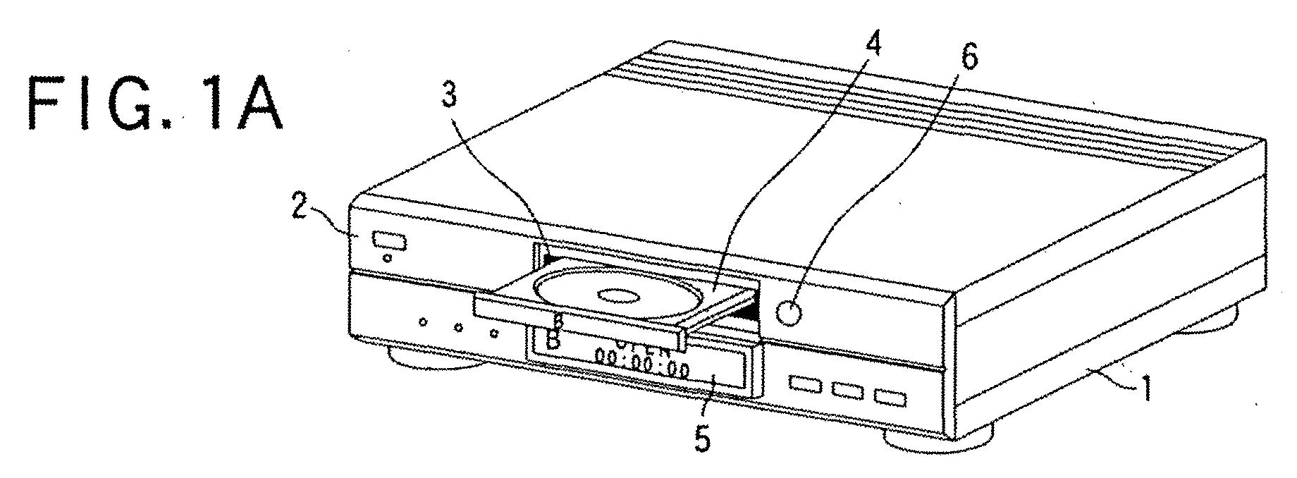
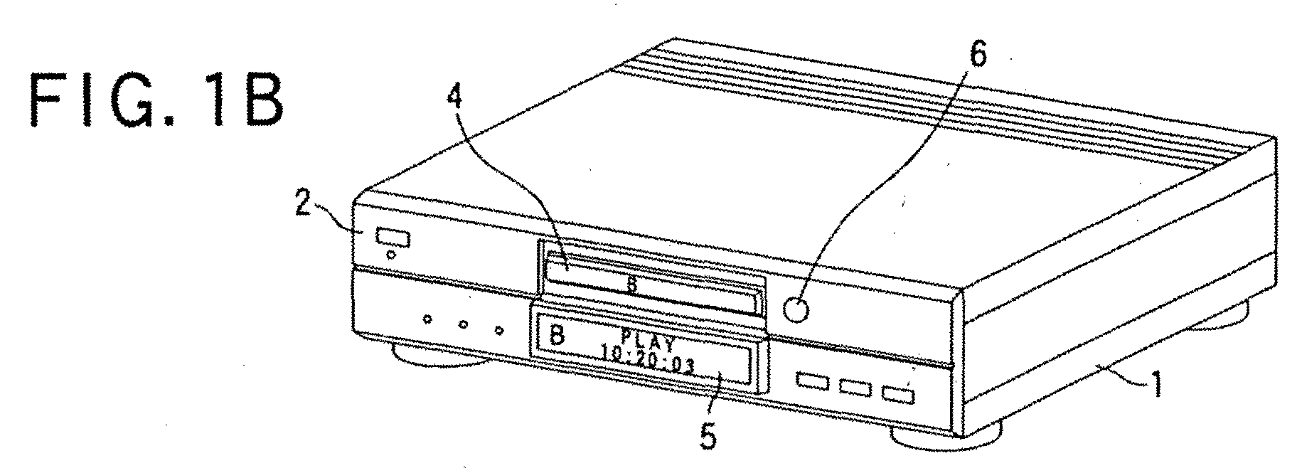
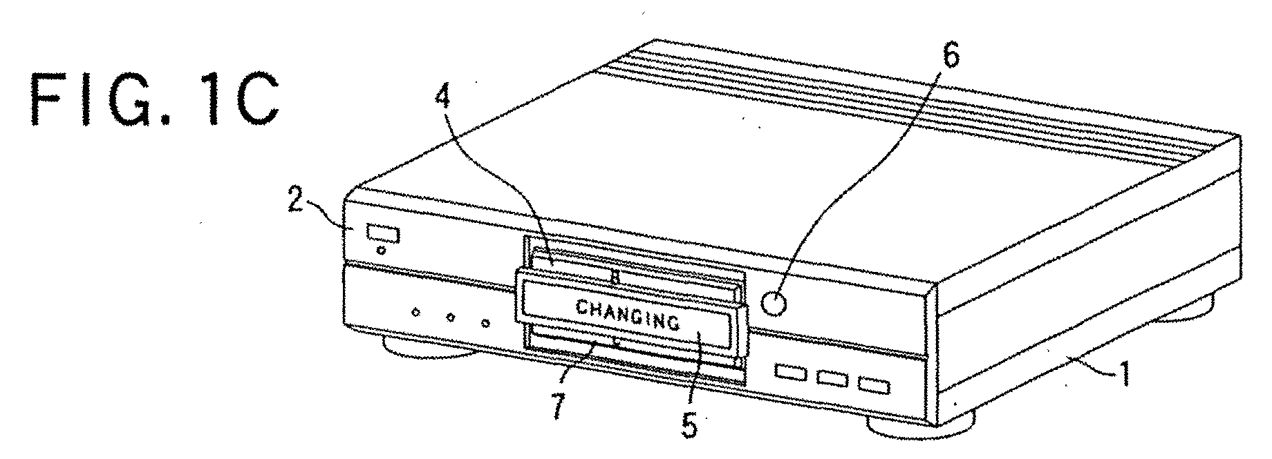
- Figs. 1A to 1D are perspective views showing driven states of a display device placed on the information recording and reproducing apparatus, in which the display device is driven by the display device driving mechanism.
- An information recording and reproducing apparatus 1 has a front panel 2. At predetermined positions of the front panel 2, two openings are formed to allow optical disks to be loaded into two drives through the openings, respectively.
- the two drives which consist of D and B drives, are formed in compliance with two types of different optical disks and placed independently within the apparatus.
- An optical disk is laid on a disk tray composing part of the D drive, and then pulled, as the disk is laid thereon, into the D drive body through one of the two openings.
- another optical disk is laid on a disk tray composing part of the B drive, and then pulled, as the disk is laid thereon, into the B drive body through the other opening.
- the optical disks, which are loaded individually into the D and B drives, are rotated for reproducing or recording bits of information.
- Fig. 1A depicts one state of the two drives incorporated in the information recording and reproducing apparatus 1, in which the B drive is driven such that a disk tray 4, which composes part of the B drive, is pulled out forward for accepting an optical disk thereon.
- an opening 3 are formed, through which the disk tray 4 with an optical disk (not shown) placed thereon can be passed.
- the information recording and reproducing apparatus 1 has also a display device 5 which serves as display means for providing an operation state of the apparatus 1.
- This display device 5 is formed to have a size fitting to each opening. In the situation shown in Fig. 1A, the display device 5, which has been transferred from other positions, is located at a position of the opening for the D drive so that the opening is masked, during which time the display 5 shows that the B drive is in operation at present.
- a drive selecting switch 6 is disposed, which can be used for selecting, from the D and B drives, either one drive to be driven.
- the disk tray 4 When an optical disk in compliance with the standard for the B drive on the disk tray 4, the disk tray 4 is driven to be pulled into the information recording and reproducing apparatus 1, as shown in Fig. 1B, while the optical disks is kept on the disk tray 4. As a result, the optical disk is loaded into the B drive. Then the optical disk is subjected to recording or reproducing information onto or from the optical disk laid on the disk tray in the B drive. In this situation, as shown in Fig. 1B, an operation state of the optical disk loaded in the B drive is displayed on the display device 5.
- a transfer from the driven state of the B drive shown in Fig. 1B to a driven state of the D drive is triggered by a manual operation at the drive selecting switch 6 on the front panel 2.
- This manual operation is carried out when the B drive is in operation as shown in Fig. 1B.
- the display device 5 which has been located at the position lower than the upper opening 3 so far, is driven to move upward along the front panel 2, as shown in Fig. 1 C.
- the display device 5 provides a display state showing that the drives are under switching operation.
- a lower opening 8 for the D drive appears at its lower predetermined position.
- a disk tray 7 for the D drive is exposed to the external field, whereby the D drive becomes available.
- the disk tray 7 is pulled out forward to lay an optical disk in compliance with the standard for the D drive. This enables the optical disk to be loaded into the D drive.
- the optical disk placed on the disk tray 7 is then driven to be pulled back into the D drive, whereby the optical disk can be loaded into the D drive.
- the optical disk is subjected to recording and reproducing bits of information.
- a transfer mechanism for transferring the display device 5 as shown in Figs. 1A to 1D will now be described.
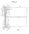
- Fig. 2 shows a side view of a drive unit DV1 which has been taken out of the information recording and reproducing apparatus 1, the drive unit DCV1 being provided with the transfer mechanism, display unit 5, B drive and D drive.
- the drive unit DV1 includes a B drive 10 and a D drive 11 which are superposed one on the other in the upper and lower direction and secured by an upper frame 13 and a lower frame 14, respectively.
- the disk trays 3 and 7 are exposed in part to the external field.
- guides 23 for the display unit 5 are disposed on the frontal both sides of the B and D drives so as to connect the upper and lower frames 13 and 14. The guides 23 are thus able to move up or down in Fig. 2.
- Fig. 2 shows only one of both the guides 23 disposed on both the longitudinal sides of the drives.
- Rod-like supports 21 and 22 both firmly coupled with the display device 5 are fit, but movable, into the slits 24 formed in the guides 23, respectively. Hence the display device is supported in front of both the B and D drives 10 and 11 and can be driven to transfer in the up and down direction.
- Pulleys 17 and 16 are rotatably arranged on the upper and lower frames 13 and 14, respectively.
- a timing belt 18 is bridged over both the pulleys 17 and 16.
- timing belt 18 On this timing belt 18 is secured the fitting member 20.
- the pulley 17, serving as transfer means is driven by an electric motor 12
- the timing belt 18 can rotated to circulate between the pulleys 17 and 16.
- This circulation provides upward and downward transfers of the belt 18, as shown by arrows in Fig. 2.
- These transfers of the belt 8 enable the display device 5 to transfer in the up and down direction in Fig. 2 along the frontal surfaces of the B and D drives.
- a switch 30 is secured on the upper frame 13 so as to detect an upward transfer of the display device 5.
- the switch 30 is turned on, and then outputs a switch signal showing the "on" state.
- a witch 32 is secured on the lower frame 14 so as to detect a downward transfer of the display device 5.
- the switch 32 is turned on, and then outputs a switch signal showing the "on" state.
- Figs. 3A to 3C show side views of the drive unit DV1, which are depicted to explain various transfer positions of the display device 5.
- the upper edge of the display device 5 comes in touch with the switching segment of the upper switch 30.
- the upper switch 30 to continue outputting a switch signal indicating that the display unit 5 is currently located at the top position along the guides 23.
- the switching segment of the lower switch 32 is made open, so that no signal is provided from this lower switch 32.
- a later-described CPU control issues a command to transfer the display device 5 downward in Fig. 3A, and this command is sent to the motor 12.
- the motor 12 In response to the reception of this command, the motor 12 is driven to rotate one (17) of the pulleys 16 and 17.
- This drive causes the timing belt 18 to rotate counterclockwise, so that the display device 5, which is secured on the timing belt by the fitting member 20, is made to transfer downward along the guides 23, as shown from Fig. 3A to Fig. 3B.
- the lower edge of the display device 5 comes in touch with the switching segment of the upper switch 32.
- the switching segment of the upper switch 30 is made open, so that no signal is provided from this upper switch 30.
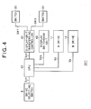
- Fig. 4 is a block diagram showing the configuration of the drive unit DV1 prepared for performing the transfer control
- Fig. 5 shows a flowchart for the transfer control.
- the transfer control requires, in addition to the foregoing drive selecting switch 6, B drive 10, and D drive 11, a CPU 40, a display-device transferring controller 41 connected to the switches 30 and 32, and a display switchover unit 42 to switch displayed contents on the display device 5.
- the drive selecting switch 6 on the front panel 2 is operated to output a switchover signal Sch serving as a trigger (step S1 in Fig. 5).
- the CPU 40 examines the switchover signal Sch to determine whether or not either the D mode or the B mode should be active in operating the information recording and reproducing apparatus (step S2 in Fig. 5).
- the switchover signal Sch reveals that a mode to be operated is the D mode (D at step S2)
- step S3 when the determination at step S3 shows that the information recording and reproducing apparatus 1 is now in operation in the B mode (i.e., the switch signal SW3 is outputted from the lower switch 32; NO at step S3), it is required that an operation carried out at the drive selecting switch 6 be reflected in the transfer control. That is, the current B mode should be changed to the D mode.
- a control signal Sb to stop the B drive 10 is first sent to the B drive 10 (step S5), and then the display device 5 is made to transfer toward the B drive 10 in such a manner as shown in Figs. 3A to 3C (step S6).
- the CPU 40 outputs a control signal Sdp to the display switchover unit 42 to indicate that the display device 5 is now in transfer (refer to Fig. 1 C) .
- step S7 when it is confirmed based on the switch signal SW 1 from the upper switch 30 that the display device 5 has reached the top position along the guides 23, recognition is made such that a necessary transfer of the display device 5 has been completed.
- the displayed content on the display device 5 is switched to the D mode and a control signal Sd is outputted to the D drive 11 so that the D drive is brought into a waiting state (step S7).
- step S2 when the switchover signal Sch reveals at step S2 that a mode to be operated is the B mode (B at step S2), it is determined through the display-device transferring controller 41 whether or not either the switch signal SW1 or SW3 is outputted form either the switch 30 or 32. That is, it is determined if the current operation state of the information recording and reproducing apparatus 1 is based on the B mode (step S8). If it is found that the apparatus 1 is in operation in the B mode (i.e., the switch signal SW3 is outputted from the lower switch 32; YES at step S8), the control will not be carried out for transfers of the display device 5, with the control brought into a waiting state, because there is no need for transferring the display device 5 (step S9).
- step S8 shows that the information recording and reproducing apparatus 1 is now in operation in the D mode (i.e., the switch signal SW1 is outputted from the upper switch 30; NO at step S8)
- a control signal Sb to stop the D drive 10 is first sent to the D drive 11 (step S10), and then the display device 5 is made to transfer toward the D drive 11 in such a manner as shown in Figs. 3A to 3C (step S11).
- the CPU 40 outputs a control signal Sdp to the display switchover unit 42 to indicate that the display device 5 is now in transfer (refer to Fig. 1 C) .
- step S7 when it is confirmed based on the switch signal SW3 from the lower switch 32 that the display device 5 has reached the bottom position along the guides 23, recognition is made such that a necessary transfer of the display device 5 has been completed.
- the displayed content on the display device 5 is switched to the B mode and a control signal Sd is outputted to the B drive 10 so that the B drive is brought into a waiting state (step S7).
- the drive unit DV1 is incorporated in the information recording and reproducing apparatus having two openings 3 and 8 through each of which an optical disk can be passed for loading or unloading.
- This apparatus has the display device 5 to display an operation state of the drive unit DV1.
- the drive unit DV1 has two drives correspondingly to the individual openings 3 and 8.
- the display device 5 is made to transfer to a position in front of a remaining opening other than the opening 3 or 8 through which the optical disk is made to pass. That is, the remaining opening 8 or 3, which is located in front of the opening to the drive which is not in operation, is masked by the display device 5.
- a design of the front of the apparatus can be sophisticated. In addition, it is possible for users to quickly recognize which drive is in operation at present.
- the display device 5 provides information about an operation state of an optical disk loaded in either drive that has been used, but is located to mask either opening which is not used for loading or unloading an optical disk. Both of a displayed content on the display device 5 and an optical disk corresponding to the displayed content can easily be related to each other.
- the foregoing first embodiment can be modified as shown in Figs. 6A to 6C.
- the B-mode-drive disk tray 4 on which an optical disk is laid but is not in operation is allowed to advance forward to form a frontal plane equal to the display device 5. This will give more sophisticated design to the front of the apparatus.
- the disk tray 4 that has advanced is pulled back, before the display device 5 is moved (refer to Fig. 6B). If the display device 5 has already been transferred but the D drive 11 is yet to be operated (refer to Fig. 6C), the D-mode-drive disk tray 7 can be made to advance forward, like the above, so as to form a frontal plane equal to the display device 5.
- FIG. 7 an information recording and reproducing apparatus according to a second embodiment of the present invention will now be described.
- Fig. 7 the similar or identical components to those shown by the information recording and reproducing apparatus 1 according to the first embodiment are explained with the same references for the sake of avoiding a redundant explanation.
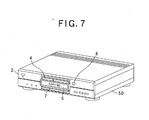
- Fig. 7 is a perspective view of an information recording and reproducing apparatus 50 according to the second embodiment, the apparatus 50 having a display-device driving mechanism for driving the display device 5.
- the display device 5 is shown so that it is located at a certain driven position.
- the display device 5 has been described such that the display 5 is able to transfer in a simple reciprocating manner between the two positions located in front of the B and D drives 10 and 11.
- the display-device driving mechanism is configured so that, in addition to the foregoing reciprocating movements, the display device 5 can be stopped at a middle position between the two locations in front of the B and D drives 10 and 11, as shown in Fig. 7.
- Such a stop at the middle position becomes required when two optical disks in compliance with the individual standards are simultaneously in operation in both the D drive 11 and the B drive 10.
- This second embodiment is not limited to such a stop, but the display device 5 under the stop at the middle position provides display indicating that, for example, it is now under copy of information.
- FIG. 8 A transfer mechanism for transfer and stopping the display device 5 will now be described with reference to Fig. 8.
- This transfer mechanism is able to operate as explained in the first embodiment, as a mater of course.
- Fig. 8 the similar or identical components to those of the drive unit DV1 explained in the first embodiment are explained by the same references and omitted from being detailed.
- Fig. 8 is a side view a drive unit DV2 containing the transfer mechanism, display device 5, B drive 10, and D drive 11, the drive unit DV2 being shown by being removed from the information recording and reproducing apparatus according to the second embodiment.
- the drive unit DV2 comprises a switch 31 placed at a middle between the B and D drives 10 and 11 so as to contact the fitting member 20 under a transfer.
- This switch 31 is configured to turn on when the display device 5 moves up or down at the middle position between the B and D drive 10 and 11 and supplies a switch signal indicating that the switch 31 has been turned on.
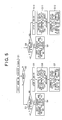
- Figs. 9A to 9C are side views of the drive unit DV2, each showing a transfer step of the display device 5.
- the upper switch 30 continues outputting a switch signal indicating that the display unit 5 is currently located at the top position along the guides 23, like the foregoing embodiment.
- a later-described CPU control issues a command to transfer the display device 5 downward in Fig. 9A, the command being for copying bits of information between optical disks loaded in the information recording and reproducing apparatus 50, and this command is sent to the motor 12.
- the motor 12 In response to the reception of this command, the motor 12 is driven to rotate one (17) of the pulleys 16 and 17.
- This drive causes the timing belt 18 to rotate counterclockwise, so that the display device 5, which is secured on the timing belt 18 by the fitting member 20, is made to transfer downward along the guides 23, as shown from Fig. 9A to Fig. 9B.
- This downward transfer is made so that the display device 5 is lowered down to a middle position between the B and D drives 10 and 11.
- the fitting member 20 connected to this display device 5 is forced to come in touch with a switching segment of the switch 31. This permits the switch 31 to output a switch signal indicating that the display device 5 has arrived at the middle position.
- Fig. 10 is a block diagram showing the configuration of the drive unit DV2 prepared for performing the transfer control, while Fig. 11 shows a flowchart for the transfer control.
- the switch 31 is additionally involved so that the switch signal from the switch 31 is sent to the display-device transferring controller 41.
- the drive selecting switch 6 on the front panel 2 is operated to output a switchover signal Sch serving as a trigger (step S20 in Fig. 11).
- the CPU 40 examines the switchover signal Sch to determine that any one of the D mode, the B mode, or a mode under which information is copied from one optical disk to the other optical disk (hereinafter referred to as "copy mode") should be active in operating the information recording and reproducing apparatus 50 (step S21 in Fig. 11).
- the switchover signal Sch reveals that a mode to be operated is the D mode (D at step S21)
- step S22 shows that the information recording and reproducing apparatus 50 is now in operation in the B mode (i.e., the switch signal SW3 is outputted from the lower switch 32; NO at step S22), it is required that an operation carried out at the drive selecting switch 6 be reflected in the transfer control. That is, the current B mode should be changed to the D mode.
- a control signal Sb to stop the B drive 10 is first sent to the B drive 10 (step S24), and then the display device 5 is made to transfer toward the B drive 10 in such a manner as shown in Figs. 9A to 9C (step S25).
- the CPU 40 outputs a control signal Sdp to the display switchover unit 42 to indicate that the display device 5 is now in transfer (refer to Fig. 1C).
- step S26 when it is confirmed based on the switch signal SW 1 from the upper switch 30 that the display device 5 has reached the top position along the guides 23, recognition is made such that a necessary transfer of the display device 5 has been completed.
- the displayed content on the display device 5 is switched to the D mode and a control signal Sd is outputted to the D drive 11 so that the D drive is brought into a waiting state (step S26).
- step S21 when the switchover signal Sch reveals that a mode to be operated is the B mode (B at step S21), it is then determined through the display-device transferring controller 41 that any of the switch signals SW1, SW2 and SW3 is outputted form any of the switches 30, 31 and 32. That is, it is determined if or not the current operation state of the information recording and reproducing apparatus 50 is based on the B mode (step S32).
- step S33 If it is found that the apparatus 50 is in operation in the B mode (i.e., the switch signal SW3 is outputted from the lower switch 32; YES at step S32), the control will not be carried out for transfers of the display device 5, with the control brought into a waiting state, because there is no need for transferring the display device 5 (step S33).
- step S32 shows that the information recording and reproducing apparatus 50 is now in operation in the D mode (i.e., the switch signal SW1 is outputted from the upper switch 30; NO at step S32), it is required that an operation carried out at the drive selecting switch 6 be reflected in the transfer control. That is, the current D mode should be changed to the B mode.
- a control signal Sb to stop the D drive 10 is first sent to the D drive 11 (step S34), and then the display device 5 is made to transfer toward the D drive 11 in such a manner as shown in Figs. 9A to 9C (step S35).
- the CPU 40 outputs a control signal Sdp to the display switchover unit 42 to indicate that the display device 5 is now in transfer (refer to Fig. 1 C) .
- step S36 when it is confirmed based on the switch signal SW3 from the lower switch 32 that the display device 5 has reached the bottom position along the guides 23, recognition is made such that a necessary transfer of the display device 5 has been completed.
- the displayed content on the display device 5 is switched to the B mode and a control signal Sd is outputted to the B drive 10 so that the B drive is brought into a waiting state (step S36).
- step S21 when the switchover signal Sch shows that a mode to be operated is the copy mode ("copy" at step S21 in Fig. 11), the processing is given to steps S27 to S31. It is first determined whether or not both the B and D drives 10 and 11 are ready for optical disks for information copy (step S27). If it is found that the optical disks have already been inserted into both the drives 10 and 11 (YES at step S27), the operation mode should be switched to the copy mode in response to an operation carried out at the drive selecting switch 6. In such a case, like the control already shown together with Fig. 9B, the display device 5 is located at the middle position between the B drive 10 and the D drive 11 (step S28). During this transfer, the CPU 40 outputs a control signal Sdp to the display switchover unit 42 to indicate that the display device 5 is now in transfer (refer to Fig. 1C).
- the switch 31 When the display device 5 has finally arrived at the middle position, the switch 31 outputs the switch signal SW2 to show the arrival. In response to the output of this signal SW2, it is decided that a transfer necessary for the display device 5 has been completed (refer to Fig. 9B). Thus the display device 5 is controlled to provide another indication that the mode has been brought into the copy mode, and then an actual information-copying operation is started (step 29).
- the display device 5 is subjected to control for providing another indication that the optical disks are yet to be inserted into the drives (step S30). Then, to cope with an optical disk to be inserted from now on, the display device 5 is made to transfer to a position in front of a drive with an optical disk already inserted therein or a drive which will be charged with an optical disk in the next place (step S31). During each transfer of the display device 5, the CPU 40 outputs a control signal Sdp to the display switchover unit 42 to indicate that the display device 5 is now in transfer (refer to Fig. 1C).
- the drive unit DV2 of the second embodiment has a further advantage.
- the display device 5 is located at the middle between both the drives so that each optical disk is prevented from being ejected through each of the openings 3 and 8. Hence it is possible to eliminate the possibility that the optical disks in operation are erroneously ejected.
- the display device 5 has been described such that the display device 5 is transferred in the up and down direction defined uniquely in the state where the information recording and reproducing apparatus 1 or 50 is actually used.
- Figs. 12A to 12D there can be provided a modification, in which the openings 3 and 8, each of which forms an entrance and exist to and from each of the drives, are formed in line in a lateral direction defined uniquely in the state where an information recording and reproducing apparatus 60 is actually used.
- the display device 5 is thus configured to transfer in the lateral direction in front of both the openings 3 and 8.
- Figs. 12A to 12D details an example of the information recording and reproducing apparatus 60 configured on the basis of the laterally-transferring display device, in which the similar or identical components to those in the first embodiment are denoted by the same references for the sake of a simplified explanation.
- Fig. 12A depicts one state of two drives incorporated in the information recording and reproducing apparatus 60, in which the B drive is driven such that a disk tray 4, which composes part of the B drive, is pulled out forward for accepting an optical disk thereon.
- a display device 5 indicates a driven state of the B drive, but is transferred to locate at a position in front of the opening 8 routed to the D drive, so that that the opening 8 is masked by the display device 5.
- the disk tray 4 When an optical disk in compliance with the standard for the B drive on the disk tray 4, the disk tray 4 is driven to be pulled into the information recording and reproducing apparatus 60, as shown in Fig. 12B, while the optical disks is kept on the disk tray 4. As a result, the optical disk is loaded into the B drive. Then the optical disk is subjected to recording or reproducing information onto or from the optical disk laid on the disk tray in the B drive. In this situation, as shown in Fig. 12B, an operation state of the optical disk loaded in the B drive is displayed on the display device 5.
- a transfer from the driven state of the B drive shown in Fig. 12B to a driven state of the D drive is triggered by a manual operation at the drive selecting switch 6 on the front panel 2.
- This manual operation is carried out when the B drive is in operation as shown in Fig. 12B.
- the display device 5 which has been located on the right side of the opening 3 so far, is driven to move leftward along the openings 8 and 3 on the front panel 2, as shown in Fig. 12C.
- the display device 5 provides a display state showing that the drives are under switching operation.
- the rightward opening 8 for the D drive appears at its left-side predetermined position.
- a disk tray 7 for the D drive is exposed to the external field, whereby the D drive becomes available.
- the disk tray 7 is pulled out forward to lay an optical disk in compliance with the standard for the D drive. This enables the optical disk to be loaded into the D drive.
- the optical disk placed on the disk tray 7 is then driven to be pulled back into the D drive, whereby the optical disk can be loaded into the D drive.
- the optical disk is subjected to recording and reproducing bits of information.
- the guides 23 shown in the drive unit DV1 or DV2 according to the first or second embodiment can be used with some modifications. Namely, such guides 23 are placed on the front panel 2 to locate in parallel at the upper and lower ends of a lateral region along which the display device 5 transfers. Hence, along the guides 23, the display device 5 is transferred in the light and left (lateral) direction in each of Figs. 12A to 12B.
- an opening 8 or 3 other than an opening 3 or 8 for a disk in which an optical disk has been inserted and in operation is masked. It is therefore possible to provide a more polished design to the front panel 2. In addition, it is possible for users to quickly recognize which drive is in operation at present.
- the display device 5 which masks either the opening 3 or 8 for a drive in which an optical disk is yet to be loaded, indicates an operation state of an optical disk that has been loaded in a disk for operation.
- the display device 5 in cases where plural optical disks are concurrently in operation, the display device 5 is transferred to locate at a position that enables the display device 5 to prevent plural optical disks from being ejected.
- the optical disks in operation are erroneously ejected though the opening 3 or 8.
- a program that corresponds to the flowchart shown in Fig. 5 or 11 can be stored in advance in an information recording medium, such as flexible disk or hard disk, or can previously be downloaded from a site through a communication network such as Internet and stored in various mediums.
- an information recording medium such as flexible disk or hard disk
- Such a medium with the program stored is applied to a universal microcomputer so that it reads the program for execution.
- the microcomputer can be used instead of the foregoing CPU 40.
Landscapes
- Devices For Indicating Variable Information By Combining Individual Elements (AREA)
- Feeding And Guiding Record Carriers (AREA)
- Indexing, Searching, Synchronizing, And The Amount Of Synchronization Travel Of Record Carriers (AREA)
- Management Or Editing Of Information On Record Carriers (AREA)
- Control Of Indicators Other Than Cathode Ray Tubes (AREA)
Abstract
Description
Claims (6)
- An information processing apparatus (1, 50, 60) in which pluralities of openings (3, 8) are formed to allow an information recording medium to pass through each of the openings, characterized in that the apparatus comprising:a display device (5) configured to display an operation state of the information processing apparatus and to be transferable in front of the plurality of openings; anda transfer unit (6, 40, 41, 42, 30, 32) configured to control the display device so that the display device is transferred to a position at which the display device masks, of the plurality of openings, another opening other than a particular opening through which an information recording medium in operation is allowed to pass.
- The information processing apparatus according to claim 1, characterized in that the display device is configured to display an operation state of the recording medium in operation in cases where the display device is transferred to the position at which the display device masks another opening.
- The information processing apparatus according to either claim 1 or 2, characterized in that the transfer unit configured to control the transfer of the display device so that the display device is located at a position that prevents the recording medium from being ejected through a particular opening of the plurality of opening, the recording medium being loaded through the particular opening into the information processing apparatus and being in operation.
- A method of controlling a transfer of a display device (5) equipped on an information processing apparatus (1, 50, 60) in which a plurality of openings (3, 8) are formed to allow a recording medium to pass through each opening when being loaded or unloaded into or from the information processing apparatus, information indicative of an operation state of the information processing apparatus being provided by the display device, characterized in that the method comprising the steps of:detecting information showing that an information medium in operation is loaded through which opening;detecting a current location of the display device; andcontrolling, based on the detected information and the detected current location, the display device so that the display device is transferred to a position at which the display device masks, of the plurality of openings, another opening other than a particular opening through which an information recording medium in operation is allowed to pass.
- An information processing program readable by a computer incorporated in an information processing apparatus (1, 50, 60) in which a plurality of openings (3, 8) are formed to allow a recording medium to pass through each opening when being loaded or unloaded into or from the information processing apparatus, information indicative of an operation state of the information processing apparatus being provided by a display device (5), wherein
the program makes the computer have a function of controlling the display device so that the display device is transferred to a position at which the display device masks, of the plurality of openings, another opening other than a particular opening through which an information recording medium in operation is allowed to pass. - An information recording medium in which a computer-readable program is recorded, the program being readable by a computer incorporated in an information processing apparatus (1, 50, 60) in which a plurality of openings (3, 8) formed to allow a recording medium to pass through each opening when being loaded or unloaded into or from the information processing apparatus, information indicative of an operation state of the information processing apparatus being provided by a display device (5), wherein
the program makes the computer have a function of controlling the display device so that the display device is transferred to a position at which the display device masks, of the plurality of openings, another opening other than a particular opening through which an information recording medium in operation is allowed to pass.
Applications Claiming Priority (2)
| Application Number | Priority Date | Filing Date | Title |
|---|---|---|---|
| JP2002287326A JP2004127371A (en) | 2002-09-30 | 2002-09-30 | Information processor, moving method, information processing program, and information recording medium |
| JP2002287326 | 2002-09-30 |
Publications (2)
| Publication Number | Publication Date |
|---|---|
| EP1406264A2 true EP1406264A2 (en) | 2004-04-07 |
| EP1406264A3 EP1406264A3 (en) | 2007-04-25 |
Family
ID=31987135
Family Applications (1)
| Application Number | Title | Priority Date | Filing Date |
|---|---|---|---|
| EP03021649A Withdrawn EP1406264A3 (en) | 2002-09-30 | 2003-09-26 | Information processing apparatus with transferable display device on front thereof |
Country Status (4)
| Country | Link |
|---|---|
| US (1) | US20040062174A1 (en) |
| EP (1) | EP1406264A3 (en) |
| JP (1) | JP2004127371A (en) |
| CN (1) | CN1497599A (en) |
Family Cites Families (8)
| Publication number | Priority date | Publication date | Assignee | Title |
|---|---|---|---|---|
| JPS5933601A (en) * | 1982-08-19 | 1984-02-23 | Canon Electronics Inc | Magnetic disk device |
| ATE112645T1 (en) * | 1990-05-22 | 1994-10-15 | Siemens Ag | OPERATING AND DISPLAY DEVICE FOR TRAFFIC INFORMATION IN A MOTOR VEHICLE. |
| JPH10166957A (en) * | 1996-12-12 | 1998-06-23 | Calsonic Corp | On-vehicle monitoring device |
| US6243328B1 (en) * | 1998-04-03 | 2001-06-05 | Sony Corporation | Modular media storage system and integrated player unit and method for accessing additional external information |
| DE29909912U1 (en) * | 1999-06-08 | 1999-08-12 | Becker GmbH, 76307 Karlsbad | Car radio |
| ITMI20010163A1 (en) * | 2000-02-03 | 2002-07-30 | Preh Elektro Feinmechanik | COVER FOR A BLOCK OF APPLIANCES |
| DE10106965B4 (en) * | 2001-02-15 | 2006-02-09 | Grundig Multimedia B.V. | Radio receiver |
| JP4180281B2 (en) * | 2002-02-14 | 2008-11-12 | 松下電器産業株式会社 | Display device |
-
2002
- 2002-09-30 JP JP2002287326A patent/JP2004127371A/en active Pending
-
2003
- 2003-09-26 EP EP03021649A patent/EP1406264A3/en not_active Withdrawn
- 2003-09-29 CN CNA03124887XA patent/CN1497599A/en active Pending
- 2003-09-30 US US10/673,515 patent/US20040062174A1/en not_active Abandoned
Also Published As
| Publication number | Publication date |
|---|---|
| CN1497599A (en) | 2004-05-19 |
| EP1406264A3 (en) | 2007-04-25 |
| US20040062174A1 (en) | 2004-04-01 |
| JP2004127371A (en) | 2004-04-22 |
Similar Documents
| Publication | Publication Date | Title |
|---|---|---|
| JP5532222B2 (en) | Projector and control method | |
| JP4664448B2 (en) | Electronic device connectable with external device and optical disk playback device | |
| US7456979B2 (en) | Apparatus having means for printing video signals of video camera attached thereto | |
| EP1406264A2 (en) | Information processing apparatus with transferable display device on front thereof | |
| JP4144497B2 (en) | projector | |
| JPH09135377A (en) | Electronic still camera with barrier | |
| USRE39674E1 (en) | Peripheral and camera system using the same, for rewriting programs stored in a camera | |
| JPH09224176A (en) | Image display device | |
| JP4061735B2 (en) | Camera system | |
| EP0541355B1 (en) | Recording and/or reproducing apparatus | |
| JP3714556B2 (en) | Information processing device | |
| KR0147977B1 (en) | Disc and set protector and method when the optical disc player is powered off | |
| JP2508421B2 (en) | Tape deck with remote control device | |
| GB2248336A (en) | Checking for abnormal operation of a video cassette recorder | |
| JP2859810B2 (en) | Automatic recording / reproducing device for recording media | |
| JP4442950B2 (en) | Monitor movable system | |
| EP0400679B1 (en) | Recording and reproducing system | |
| JPS60247882A (en) | Display device of information recording and reproducing device | |
| KR101648450B1 (en) | Data reproducing method, and reproducing apparatus | |
| JPH10233043A (en) | Recording and reproducing device | |
| KR100719125B1 (en) | Automatic return to original playback position in case of search failure and optical regeneration device using the same | |
| KR100532613B1 (en) | Optical recording apparatus and control method thereof | |
| JP2639954B2 (en) | Empty mode detection method | |
| JPH06315189A (en) | Shared controller | |
| JP2531291B2 (en) | Magnetic recording / reproducing device |
Legal Events
| Date | Code | Title | Description |
|---|---|---|---|
| PUAI | Public reference made under article 153(3) epc to a published international application that has entered the european phase |
Free format text: ORIGINAL CODE: 0009012 |
|
| AK | Designated contracting states |
Kind code of ref document: A2 Designated state(s): AT BE BG CH CY CZ DE DK EE ES FI FR GB GR HU IE IT LI LU MC NL PT RO SE SI SK TR |
|
| AX | Request for extension of the european patent |
Extension state: AL LT LV MK |
|
| PUAL | Search report despatched |
Free format text: ORIGINAL CODE: 0009013 |
|
| AK | Designated contracting states |
Kind code of ref document: A3 Designated state(s): AT BE BG CH CY CZ DE DK EE ES FI FR GB GR HU IE IT LI LU MC NL PT RO SE SI SK TR |
|
| AX | Request for extension of the european patent |
Extension state: AL LT LV MK |
|
| AKX | Designation fees paid | ||
| STAA | Information on the status of an ep patent application or granted ep patent |
Free format text: STATUS: THE APPLICATION IS DEEMED TO BE WITHDRAWN |
|
| 18D | Application deemed to be withdrawn |
Effective date: 20071026 |
|
| REG | Reference to a national code |
Ref country code: DE Ref legal event code: 8566 |