EP1406106A1 - Multiple position lens barrel having cam cylinder with commonly biased first and second lens carriers - Google Patents
Multiple position lens barrel having cam cylinder with commonly biased first and second lens carriers Download PDFInfo
- Publication number
- EP1406106A1 EP1406106A1 EP20030077978 EP03077978A EP1406106A1 EP 1406106 A1 EP1406106 A1 EP 1406106A1 EP 20030077978 EP20030077978 EP 20030077978 EP 03077978 A EP03077978 A EP 03077978A EP 1406106 A1 EP1406106 A1 EP 1406106A1
- Authority
- EP
- European Patent Office
- Prior art keywords
- lens
- cam
- lens barrel
- biaser
- cam tracks
- Prior art date
- Legal status (The legal status is an assumption and is not a legal conclusion. Google has not performed a legal analysis and makes no representation as to the accuracy of the status listed.)
- Withdrawn
Links
- 239000000969 carrier Substances 0.000 title claims description 25
- 230000003287 optical effect Effects 0.000 claims abstract description 23
- 238000000034 method Methods 0.000 claims description 4
- 230000002596 correlated effect Effects 0.000 claims 1
- 230000003100 immobilizing effect Effects 0.000 claims 1
- 230000007246 mechanism Effects 0.000 description 4
- 230000006835 compression Effects 0.000 description 3
- 238000007906 compression Methods 0.000 description 3
- 238000004519 manufacturing process Methods 0.000 description 2
- 238000000926 separation method Methods 0.000 description 2
- 239000000853 adhesive Substances 0.000 description 1
- 230000001070 adhesive effect Effects 0.000 description 1
- 238000005266 casting Methods 0.000 description 1
- 230000000694 effects Effects 0.000 description 1
- 229920001971 elastomer Polymers 0.000 description 1
- 239000000806 elastomer Substances 0.000 description 1
- 238000003466 welding Methods 0.000 description 1
Images


Classifications
-
- G—PHYSICS
- G02—OPTICS
- G02B—OPTICAL ELEMENTS, SYSTEMS OR APPARATUS
- G02B7/00—Mountings, adjusting means, or light-tight connections, for optical elements
- G02B7/02—Mountings, adjusting means, or light-tight connections, for optical elements for lenses
- G02B7/04—Mountings, adjusting means, or light-tight connections, for optical elements for lenses with mechanism for focusing or varying magnification
- G02B7/10—Mountings, adjusting means, or light-tight connections, for optical elements for lenses with mechanism for focusing or varying magnification by relative axial movement of several lenses, e.g. of varifocal objective lens
Definitions
- the invention relates to photography and photographic equipment and more particularly relates to a multiple position lens barrel having commonly biased first and second lens carriers.
- a great many zoom lens barrels and other multiple position lens barrels are available that provide accurate and precise positioning of lens groups using complex and costly mechanisms. Those lens barrels are unsuitable for inexpensive cameras, particularly one-time-use and other simple cameras. With simple cameras, mechanisms used typically have a small number of parts that are relatively easy to manufacture and simple to assemble.
- U.S. Patent No. 5,225,939 discloses a lens barrel that has a single component having a rib for one follower on an inside wall and a groove for another cam follower on an outside wall. This lens barrel has a reduced number of pieces in comparison to the others mentioned above, but has complexly shaped pieces.
- U.S. Patents Nos. 3,672,280 and 5,289,320 disclose lens barrels having spring urged lens positions. These mechanisms are relatively simple and, in the case of U.S. Patent No. 5,289,320, include use of a cam follower and cam. These lens barrels have the shortcoming of being limited to movement of a single lens group.
- the invention in its broader aspects, provides a multiple position lens barrel that has a first lens carrier defining an optical axis.
- the first lens carrier has a set of first cam followers.
- a second lens carrier is aligned with the optical axis.
- the second lens carrier has a set of second cam followers.
- a cam cylinder has a tubular wall surrounding a passage aligned with the optical axis.
- the cam cylinder has a set of one or more first cam tracks and a set of one or more second cam tracks.
- the first and second cam tracks are axially spaced apart. Each cam track extends away from the wall in a radial direction.
- Each cam track extends along and about the optical axis.
- a biaser biases the cam followers toward respective cam tracks.
- the multiple position lens barrel 10 has first and second lens carriers 12,13, a biaser 14, and a mount-cam cylinder 16 aligned along an optical axis 18 defined by the lens carriers 12,13.
- Each lens carrier 12,13 of the lens barrel 10 is configured to hold a lens group 20,21.
- Each lens group 20,21 can have one or more lens elements 22.
- the lens barrel components provide for movement of the front and rear lens groups 20,21 relative to the focal plane of the lens system and each other. The manner in which these optical relationships change during relative movement and the shapes of cams (described below) that provide those changes is a function of the design of the lens system. Suitable lens systems are well known to those of skill in the art.
- Both lens carriers 12,13 have a cap 24,26 attached to a retainer 28,30 with the lens elements 22 held between the two.
- Lens carriers 12,13 can include additional parts and one or more parts can be molded together in a single structure.
- the respective caps 24,26 and retainers 28,30 are held together by friction fit or engaging features, such as reciprocal threads, or by fasteners, or adhesive, sonic welding, or the like.
- the lens elements 22 can likewise be held in place in a similar manner.
- the caps 24,26 are located axially outward relative to respective retainers 28,30, but one or both retainers 28,30 can instead be outermost.
- front caps 24 and front retainers 28 are screwed together and rear caps 26 and rear retainers 30 are friction fit together.
- a single front lens element 22a is trapped between a front cap 24 and front retainer 28 and first and second rear lens elements 22b,22c are trapped between a rear cap 26 and rear retainer 30.
- the front and rear retainers 28,30 each have a set of one or more cam followers 32,34 (also referred to herein as first cam followers 32 and second cam followers 34, respectively). Shapes and relative locations of the cam followers 32,34 are discussed below, in relation to the cam cylinder 48.
- the cam followers 32,34 can be separate parts, but are preferably molded in features of the retainers 28,30, such as posts or tabs.
- the cam followers 32,34 each extend away from the remainder of the respective retainer 28,30.
- Axial slots 37 can be provided in one or both retainers to allow cam follower to protrude through to the respective cam tracks.
- Each lens carrier 12,13 has a seat 36,38 for the biaser 14.
- the seats 36,38 can be part of the respective retainers 28,30, as shown in Figure 7.
- One or both biaser seats 36,38 can also be provided on other components of the lens carriers 12,13, including portions of the lens elements 22 that are outside the light path of the lens barrel 10. This is illustrated in Figure 5.
- the biaser 14 is resilient and can consist of one or more springs, with or without an additional supporting structure.
- the biaser 14 acts as either a tension spring or a compression spring, acting in directions along the optical axis 18. Coil springs are illustrated. Other types of springs, including elastomer elements, can be used in addition or in place of the springs shown.
- the biaser 14 is a single coil spring 14a that is sized to fit within the mount-cam cylinder 16. Opposed ends 40 of the biaser 14 bear on edges of the two retainers 28,30. The inner diameter of the spring 14a is also larger than the diameter of the light path through the lens barrel 10, so that the spring 14a does not interfere with the optical system.
- the biaser 14 is three small diameter coil springs 14b and the biaser seats 36,38 are each a set of three holdfasts 42,44 that are configured to retain respective ends 40 of the springs 14b.
- the mount-cam cylinder 16 includes a mount 46 and a cam cylinder 48.
- the cam cylinder 48 is immobile relative to the mount 46.
- the mount 46 is adapted to be joined in immobile relation to a camera body 50 (shown in Figure 1).
- the lens barrel is attached to an internal frame 51 (shown in Figure 3), within the camera body 50.
- the lens barrel 10 can also be attached to the outside of the camera body 50.
- the mount-cam cylinder 16 can be a two piece assembly, but assembly is simpler, if the mount-cam cylinder 16 is manufactured as a one-piece plastic casting.
- the cam cylinder 48 has a tubular wall 52 that surrounds a passage 54.
- the mount 46 surrounds a continuation of the passage 54.
- the passage 54 defines and is cocentric with the optical axis 18 of the lens barrel 10. (All terminology used herein that relates to an axis, such as “radial” and “axial”, is relative to the optical axis 18. For example, "a radial” direction is in a plane perpendicular to the optical axis 18 and an "axial" direction parallels or coextends with the optical axis 18.)
- the mount 46 has an attachment feature 56 that is used to hold the lens barrel 10 in place against the camera body 50.
- the type and configuration of attachment feature 56 can be any of the many types that have been used in the past, such as: reciprocal screw threads, bayonet mounts, friction fit, adhered or mechanical fastened parts, or the like.
- the mount 46 has two pair of opposed snap hooks 58 and one of two different locating pins 60 positioned between members of each pair of snap hooks 58.
- the hooks 58 and pins 60 extend outward from a cowl 62 that is shaped so as to overlap part of the camera body 50.
- the cowl 62 can provide light locking to reduce any risk of flare.
- the cam cylinder 48 extends axially outward and forward from the mount 46.
- the wall 52 of the cam cylinder 48 has a set of one or more first cam tracks 64 and a set of one or more second cam tracks 66.
- the cam tracks 64,66 and cam followers 32,34 are matched one-to-one. Each cam track 64,66 engages a respective cam follower 32,34. Numbers of cam followers 32,34 and cam tracks 64,66, in each set, can be changed.
- the first cam tracks 64 and second cam tracks 66 are spaced apart in an axial direction.
- the cam tracks 64,66 can be parts of slots in the cam cylinder 48, but are preferably in the form of rails that protrude from the wall 52 of the cam cylinder 48 in a radial direction or axially at an end of the cam cylinder.
- Cam tracks 64,66 in the form of rails increase the strength of the cam cylinder 48 and assembly of parts during manufacturing can be simpler. In the following discussion and in the drawings all of the cam tracks 64,66 are rails.
- the biaser 14 biases the cam followers 32,34 against respective cam tracks 64,66. If the biaser 14 acts as a compression spring, then the lens carriers 12,13 are biased away from each other in axial directions. If the biaser 14 acts as a tension spring, then the lens carriers 12,13 are biased toward each other in axial directions.
- the cam tracks 64,66 are oriented so as oppose the biasing of the biaser 14. In the embodiment of Figure 5, second cam tracks 66 are axially forward of first cam tracks 64. In the embodiment of Figure 7, first cam tracks 64 are axially forward of second cam tracks 66.
- Cam followers 32,34 are positioned so as to engage the respective cam tracks 64,66.
- the biaser 14 biases the cam followers 32,34, in axial directions, toward respective cam tracks 64,66. The two different axial directions are away from each other, if the biaser 14 acts as a compression spring; and toward each other, if the biaser 14 acts as a tension spring.
- the wall 52 of the cam cylinder 48 has an inner face 68 adjoining the passage 54 and an outer face 70 opposite the inner face 68.
- one set of cam tracks 64 or 66 extends radially inward from the inner face 68. These cam tracks 64 or 66 are disposed interior to the wall 52 and within the passage 54.
- a second set of cam tracks 66 or 64 can likewise extend radially inward from the inner face 68. This is the case with the lens barrel 10 of Figure 5.
- the second set of cam tracks 66 or 64 can, alternatively, extend outward from the outer face 70 of the wall 52 or form a rim between inner and outer faces 68,70 at the end of the wall 52.
- the latter is shown in Figure 7.
- it is preferred that one of the sets of cam tracks 64 or 66 is located radially inward from the other set. This is the case with the embodiments illustrated.
- the lens carriers 12,13 are continuously biased toward respective default positions by the biaser 14.
- the default position for the lens barrel 10 of Figure 5 is at a maximum separation of the lens groups 20. With a zoom wide-telephoto lens system, this is the wide angle position.
- the default position for the lens barrel 10 of Figure 7 is at a minimum separation of the lens groups 20. With the same wide-telephoto lens system, this is the telephoto position.
- the relative positions of the lens carriers 12,13 is changed by moving one of the lens carriers 12 or 13 relative to the mount-cam cylinder 16 and relative to the other lens carrier 13 or 12.
- cam tracks 64,66 guide the respective cam followers 32,34 along paths that curve about and extend along the optical axis 18, in a spiral or more complex curve determined by the optical design of the lens system.
- One of the two lens carriers 12,13 is connected to a driver 72, which rotates one of the lens carriers 12,13, causing cam followers 32,34 of both carriers 12,13 to move along the respective cam tracks 64,66 to a new combination of locations of the cam followers 32,34 on respective cam tracks 64,66.
- the driver 72 illustrated in the figures is a lever that is joined to the retainer 28 of the front lens carrier 12.
- the driver 72 can be molded as a part of the front retainer 28.
- the driver 72 can be manipulated directly by the user.
- the lens barrel 10 can be covered by a shroud 73 and the driver 72 can be moved by user manipulation of a slider or other control feature 74 that is engaged or meshed with the driver 72.
- Other types of user controls can also be used.
- the driver 72 can be a gear or gear train meshed with teeth formed on the circumference of one of the lens carriers 12,13.
- the driver 72 can be a motor or can include a motor.
- the lens barrel 10 includes a clutch 76 that holds the lens carriers 12,13 in a selected position against the biasing of the biaser 14.
- the clutch 76 is independent of the biaser 14 so as to avoid a risk of binding during use.
- the clutch 76 can be limited to one or more predetermined lens carrier positions or can hold the lens carriers 12,13 at any possible position. The latter case is illustrated in the figures.
- At the end of the driver 72 is a flexible pawl 78 that engages teeth 80 molded into the mount-cam cylinder 16.
- the pawl 78 is bent outward slightly to release the pawl 78, allowing the user to manipulate the driver 72 and zoom the lens carriers between positions.
- This clutch 76 can be limited to predetermined positions by provision of teeth 80 at only those positions.
- the lens barrel 10 can be limited to two positions: full telephoto and full wide angle.
- the clutch 76 can hold the lens carriers 12,13 at one position, with the other position being a default, or the clutch 76 can hold at both positions.
Landscapes
- Physics & Mathematics (AREA)
- General Physics & Mathematics (AREA)
- Optics & Photonics (AREA)
- Lens Barrels (AREA)
Abstract
A multiple position lens barrel (10) has a first lens carrier (12) defining an
optical axis. The first lens carrier (12) has a set of first cam followers (32). A second lens
carrier is aligned with the optical axis (18). The second lens carrier (13) has a set of second
cam followers (34). A cam cylinder has a tubular wall surrounding a passage (54) aligned
with the optical axis. The cam cylinder has a set of one or more first cam tracks (64)
and a set of one or more second cam tracks (66). The first and second cam tracks are
axially spaced apart. Each cam track extends away from the wall in a radial
direction. Each cam track extends along and about the optical axis. A biaser (14)
biases the cam followers toward respective cam tracks.
Description
- The invention relates to photography and photographic equipment and more particularly relates to a multiple position lens barrel having commonly biased first and second lens carriers.
- A great many zoom lens barrels and other multiple position lens barrels are available that provide accurate and precise positioning of lens groups using complex and costly mechanisms. Those lens barrels are unsuitable for inexpensive cameras, particularly one-time-use and other simple cameras. With simple cameras, mechanisms used typically have a small number of parts that are relatively easy to manufacture and simple to assemble.
- One of the complexities of some zoom lens barrels arises from a requirement of moving two different lens groups (a "lens group" has one or more lens elements) relative to both the focal plane and each other, in accordance with particular optical designs. A solution is the use of different, but linked mechanisms to move the two lens groups. In U.S. Patent No. 5,673,099, a cylindrical tube has a pair of differently shaped cam grooves. Cam followers joined to the two different lens groups follow respective grooves and move the lens groups accordingly, when the cylindrical tube is rotated relative to the lens groups. U.S. Patent No. 6,369,956 is similar, but separates cam grooves onto different components. U.S. Patent No. 5,216,549 discloses a lens barrel that uses a rib in place of a cam groove. U.S. Patent No. 5,225,939 discloses a lens barrel that has a single component having a rib for one follower on an inside wall and a groove for another cam follower on an outside wall. This lens barrel has a reduced number of pieces in comparison to the others mentioned above, but has complexly shaped pieces.
- U.S. Patents Nos. 3,672,280 and 5,289,320 disclose lens barrels having spring urged lens positions. These mechanisms are relatively simple and, in the case of U.S. Patent No. 5,289,320, include use of a cam follower and cam. These lens barrels have the shortcoming of being limited to movement of a single lens group.
- It would thus be desirable to provide an improved lens barrel and method in which a relatively small number of relatively simple parts can move two different lens groups relative to the focal plane and each other.
- The invention is defined by the claims. The invention, in its broader aspects, provides a multiple position lens barrel that has a first lens carrier defining an optical axis. The first lens carrier has a set of first cam followers. A second lens carrier is aligned with the optical axis. The second lens carrier has a set of second cam followers. A cam cylinder has a tubular wall surrounding a passage aligned with the optical axis. The cam cylinder has a set of one or more first cam tracks and a set of one or more second cam tracks. The first and second cam tracks are axially spaced apart. Each cam track extends away from the wall in a radial direction. Each cam track extends along and about the optical axis. A biaser biases the cam followers toward respective cam tracks.
- It is an advantageous effect of the invention that an improved lens barrel and method in which a relatively small number of relatively simple parts can move two different lens groups relative to the focal plane and each other.
- The above-mentioned and other features and objects of this invention and the manner of attaining them will become more apparent and the invention itself will be better understood by reference to the following description of an embodiment of the invention taken in conjunction with the accompanying figures wherein:
- Figure 1 is a perspective view of a camera including an embodiment of the multiple position lens barrel.
- Figure 2 is a perspective view of the lens barrel of Figure 1.
- Figure 3 is a cross-sectional view of the lens barrel of Figure 2 taken substantially along line 3-3 of Figure 4.
- Figure 4 is a rear view of the lens barrel of Figure 2.
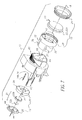
- Figure 5 is an exploded, perspective view of the lens barrel of Figure 2.
- Figure 6 is a perspective view of another embodiment of the lens barrel.
- Figure 7 is an exploded, perspective view of the lens barrel of Figure 6.
-
- The multiple
position lens barrel 10 has first andsecond lens carriers biaser 14, and a mount-cam cylinder 16 aligned along anoptical axis 18 defined by thelens carriers lens carrier lens barrel 10 is configured to hold alens group lens group rear lens groups - Both
lens carriers cap retainer Lens carriers respective caps retainers caps respective retainers retainers front caps 24 andfront retainers 28 are screwed together andrear caps 26 andrear retainers 30 are friction fit together. A single front lens element 22a is trapped between afront cap 24 andfront retainer 28 and first and secondrear lens elements rear cap 26 andrear retainer 30. - The front and
rear retainers more cam followers 32,34 (also referred to herein asfirst cam followers 32 andsecond cam followers 34, respectively). Shapes and relative locations of thecam followers cam cylinder 48. Thecam followers retainers cam followers respective retainer Axial slots 37 can be provided in one or both retainers to allow cam follower to protrude through to the respective cam tracks. - Each
lens carrier seat biaser 14. Theseats respective retainers biaser seats lens carriers lens barrel 10. This is illustrated in Figure 5. Thebiaser 14 is resilient and can consist of one or more springs, with or without an additional supporting structure. Thebiaser 14 acts as either a tension spring or a compression spring, acting in directions along theoptical axis 18. Coil springs are illustrated. Other types of springs, including elastomer elements, can be used in addition or in place of the springs shown. - In the embodiment shown in Figure 5, the
biaser 14 is a single coil spring 14a that is sized to fit within the mount-cam cylinder 16. Opposedends 40 of thebiaser 14 bear on edges of the tworetainers lens barrel 10, so that the spring 14a does not interfere with the optical system. - In the embodiment of Figure 7, the
biaser 14 is three small diameter coil springs 14b and the biaser seats 36,38 are each a set of threeholdfasts respective ends 40 of the springs 14b. - The mount-
cam cylinder 16 includes amount 46 and acam cylinder 48. In use, thecam cylinder 48 is immobile relative to themount 46. Themount 46 is adapted to be joined in immobile relation to a camera body 50 (shown in Figure 1). In the embodiments illustrated, the lens barrel is attached to an internal frame 51 (shown in Figure 3), within thecamera body 50. Thelens barrel 10 can also be attached to the outside of thecamera body 50. - The mount-
cam cylinder 16 can be a two piece assembly, but assembly is simpler, if the mount-cam cylinder 16 is manufactured as a one-piece plastic casting. Thecam cylinder 48 has atubular wall 52 that surrounds apassage 54. Themount 46 surrounds a continuation of thepassage 54. Thepassage 54 defines and is cocentric with theoptical axis 18 of thelens barrel 10. (All terminology used herein that relates to an axis, such as "radial" and "axial", is relative to theoptical axis 18. For example, "a radial" direction is in a plane perpendicular to theoptical axis 18 and an "axial" direction parallels or coextends with theoptical axis 18.) - The
mount 46 has anattachment feature 56 that is used to hold thelens barrel 10 in place against thecamera body 50. The type and configuration ofattachment feature 56 can be any of the many types that have been used in the past, such as: reciprocal screw threads, bayonet mounts, friction fit, adhered or mechanical fastened parts, or the like. In the embodiments illustrated, themount 46 has two pair of opposed snap hooks 58 and one of two different locating pins 60 positioned between members of each pair of snap hooks 58. Thehooks 58 and pins 60 extend outward from acowl 62 that is shaped so as to overlap part of thecamera body 50. Thecowl 62 can provide light locking to reduce any risk of flare. - The
cam cylinder 48 extends axially outward and forward from themount 46. Thewall 52 of thecam cylinder 48 has a set of one or more first cam tracks 64 and a set of one or more second cam tracks 66. The cam tracks 64,66 andcam followers cam track respective cam follower cam followers - The first cam tracks 64 and second cam tracks 66 are spaced apart in an axial direction. The cam tracks 64,66 can be parts of slots in the
cam cylinder 48, but are preferably in the form of rails that protrude from thewall 52 of thecam cylinder 48 in a radial direction or axially at an end of the cam cylinder. Cam tracks 64,66 in the form of rails increase the strength of thecam cylinder 48 and assembly of parts during manufacturing can be simpler. In the following discussion and in the drawings all of the cam tracks 64,66 are rails. - The
biaser 14 biases thecam followers biaser 14 acts as a compression spring, then thelens carriers biaser 14 acts as a tension spring, then thelens carriers biaser 14. In the embodiment of Figure 5, second cam tracks 66 are axially forward of first cam tracks 64. In the embodiment of Figure 7, first cam tracks 64 are axially forward of second cam tracks 66.Cam followers biaser 14 biases thecam followers biaser 14 acts as a compression spring; and toward each other, if thebiaser 14 acts as a tension spring. - The
wall 52 of thecam cylinder 48 has aninner face 68 adjoining thepassage 54 and anouter face 70 opposite theinner face 68. In particular embodiments, one set of cam tracks 64 or 66 extends radially inward from theinner face 68. These cam tracks 64 or 66 are disposed interior to thewall 52 and within thepassage 54. A second set of cam tracks 66 or 64 can likewise extend radially inward from theinner face 68. This is the case with thelens barrel 10 of Figure 5. The second set of cam tracks 66 or 64 can, alternatively, extend outward from theouter face 70 of thewall 52 or form a rim between inner andouter faces wall 52. The latter is shown in Figure 7. For convenience in assembly, it is preferred that one of the sets of cam tracks 64 or 66 is located radially inward from the other set. This is the case with the embodiments illustrated. - The
lens carriers biaser 14. The default position for thelens barrel 10 of Figure 5 is at a maximum separation of the lens groups 20. With a zoom wide-telephoto lens system, this is the wide angle position. The default position for thelens barrel 10 of Figure 7 is at a minimum separation of the lens groups 20. With the same wide-telephoto lens system, this is the telephoto position. - The relative positions of the
lens carriers lens carriers cam cylinder 16 and relative to theother lens carrier lens carriers respective cam followers optical axis 18, in a spiral or more complex curve determined by the optical design of the lens system. - One of the two
lens carriers driver 72, which rotates one of thelens carriers cam followers carriers cam followers driver 72 illustrated in the figures is a lever that is joined to theretainer 28 of thefront lens carrier 12. For simplicity, thedriver 72 can be molded as a part of thefront retainer 28. Thedriver 72 can be manipulated directly by the user. Alternatively, thelens barrel 10 can be covered by ashroud 73 and thedriver 72 can be moved by user manipulation of a slider or other control feature 74 that is engaged or meshed with thedriver 72. Other types of user controls can also be used. For example, thedriver 72 can be a gear or gear train meshed with teeth formed on the circumference of one of thelens carriers driver 72 can be a motor or can include a motor. - The
lens barrel 10 includes a clutch 76 that holds thelens carriers biaser 14. The clutch 76 is independent of thebiaser 14 so as to avoid a risk of binding during use. The clutch 76 can be limited to one or more predetermined lens carrier positions or can hold thelens carriers driver 72 is aflexible pawl 78 that engagesteeth 80 molded into the mount-cam cylinder 16. Thepawl 78 is bent outward slightly to release thepawl 78, allowing the user to manipulate thedriver 72 and zoom the lens carriers between positions. This clutch 76 can be limited to predetermined positions by provision ofteeth 80 at only those positions. For example, thelens barrel 10 can be limited to two positions: full telephoto and full wide angle. The clutch 76 can hold thelens carriers
Claims (10)
- A multiple position lens barrel comprising:a first lens carrier defining an optical axis, said lens carrier having a set of first cam followers;a second lens carrier aligned with said optical axis, said second lens carrier having a set of second cam followers;a cam cylinder having a tubular wall surrounding a passage aligned with said optical axis, said cam cylinder having a set of one or more first cam tracks and a set of one or more second cam tracks, said first cam tracks and said second cam tracks being axially spaced apart, each said cam track extending away from said wall in a radial direction, each said cam track extending along and about said optical axis; anda biaser biasing said cam followers toward respective said cam tracks.
- The lens barrel of claim 1 wherein said first cam followers are biased in a first axial direction and said second cam followers are biased in a second axial direction opposite said first axial direction.
- The lens barrel of claim 1 or 2 wherein said biaser has a plurality of spaced apart springs, each said spring having a first end attached to said first lens carrier and a second end attached to said second lens carrier.
- The lens barrel of claim 1 or 2 wherein said biaser is a single spring disposed between said lens carriers.
- The lens barrel of claim 1, 2, 3, or 4 wherein said cam tracks each face axially outward and said biaser biases said lens carriers toward each other.
- The lens barrel of claim 1, 2, 3, or 4 wherein said cam tracks each face axially inward and said biaser biases said lens carriers away from each other.
- The lens barrel of claim 1, 2, 3, 4, 5, or 6 wherein said first cam tracks are disposed axially inward from said second cam tracks.
- The lens barrel of claim 1, 2, 3, 4, 5, 6, or 7 further comprising a clutch releaseably immobilizing said lens carriers relative to said cam cylinder, said clutch being independent of said biaser.
- The lens barrel of claim 1 or 2 wherein said first cam tracks define a rim between said inner and outer faces.
- A method for positioning separately movable first and second lens groups, said method comprising the steps of:continuously biasing the first and second lens groups toward respective default positions on respective first and second lens paths;holding said lens groups in a selected pair of correlated positions on respective said first and second light paths against said biasing;repositioning said lens groups on respective said first and second light paths; andreleasing said holding, during said repositioning.
Applications Claiming Priority (2)
| Application Number | Priority Date | Filing Date | Title |
|---|---|---|---|
| US10/264,757 US6741400B2 (en) | 2002-10-04 | 2002-10-04 | Multiple position lens barrel having cam cylinder with commonly biased first and second lens carriers |
| US264757 | 2002-10-04 |
Publications (1)
| Publication Number | Publication Date |
|---|---|
| EP1406106A1 true EP1406106A1 (en) | 2004-04-07 |
Family
ID=31993587
Family Applications (1)
| Application Number | Title | Priority Date | Filing Date |
|---|---|---|---|
| EP20030077978 Withdrawn EP1406106A1 (en) | 2002-10-04 | 2003-09-22 | Multiple position lens barrel having cam cylinder with commonly biased first and second lens carriers |
Country Status (3)
| Country | Link |
|---|---|
| US (1) | US6741400B2 (en) |
| EP (1) | EP1406106A1 (en) |
| JP (1) | JP2004126587A (en) |
Cited By (3)
| Publication number | Priority date | Publication date | Assignee | Title |
|---|---|---|---|---|
| US8101173B2 (en) | 2005-12-21 | 2012-01-24 | Sentoclone International Ab | Method for treating urinary bladder cancer |
| TWI453494B (en) * | 2009-11-26 | 2014-09-21 | Hon Hai Prec Ind Co Ltd | Lens module and camera module having same |
| CN104950414A (en) * | 2014-03-24 | 2015-09-30 | 奇景光电股份有限公司 | Lens module and its assembly method |
Families Citing this family (5)
| Publication number | Priority date | Publication date | Assignee | Title |
|---|---|---|---|---|
| JP2005049599A (en) * | 2003-07-28 | 2005-02-24 | Fujinon Corp | Lens adjusting mechanism and camera |
| US7068443B1 (en) * | 2005-03-07 | 2006-06-27 | Nucam Corporation | Zoom mechanism of imaging lens module |
| KR101621895B1 (en) | 2009-12-28 | 2016-05-17 | 엘지이노텍 주식회사 | Stabilized camera module |
| WO2016109572A1 (en) * | 2014-12-29 | 2016-07-07 | Avigilon Corporation | Multi-headed adjustable camera |
| AU2018271958B2 (en) * | 2017-05-25 | 2023-06-29 | Lightforce USA, Inc., d/b/a/ Nightforce Optics, Inc. | Erector cam |
Citations (5)
| Publication number | Priority date | Publication date | Assignee | Title |
|---|---|---|---|---|
| GB333528A (en) * | 1929-05-13 | 1930-08-13 | Brooke Bond India Ltd | Improved manner of and apparatus for filling bags with finely divided or small material |
| US5376983A (en) * | 1991-05-31 | 1994-12-27 | Olympus Optical Co., Ltd. | Lens barrel |
| US5907439A (en) * | 1996-11-11 | 1999-05-25 | Fuji Photo Optical Co Ltd | Zoom lens apparatus with shared cam groove |
| US6072639A (en) * | 1998-01-29 | 2000-06-06 | Fuji Photo Optical Co., Ltd. | Zoom lens barrel assembly including a clutch mechanism for a camera |
| US20020122263A1 (en) * | 2001-03-01 | 2002-09-05 | Katsuhiko Nishikawa | Lens barrel, and cam barrel molding die |
Family Cites Families (11)
| Publication number | Priority date | Publication date | Assignee | Title |
|---|---|---|---|---|
| US3672280A (en) | 1969-05-13 | 1972-06-27 | Minolta Camera Kk | Camera with retractable lens barrel |
| ATE141693T1 (en) | 1986-05-12 | 1996-09-15 | Asahi Optical Co Ltd | INTERMEDIATE LENS CAMERA WITH ZOOMO LENS |
| JP2811185B2 (en) * | 1988-10-13 | 1998-10-15 | 日東光学株式会社 | Zoom lens device |
| JP2984330B2 (en) | 1990-07-25 | 1999-11-29 | キヤノン株式会社 | Lens barrel, flange back adjustment method and manufacturing error adjustment method |
| US5216549A (en) | 1990-08-23 | 1993-06-01 | Canon Kabushiki Kaisha | Lens barrel |
| JP2565919Y2 (en) | 1991-01-23 | 1998-03-25 | 旭光学工業株式会社 | Lens drive spring device |
| US5381272A (en) * | 1992-01-27 | 1995-01-10 | Nikon Corporation | Lens barrel with improved drum arrangement |
| JP3276171B2 (en) * | 1992-08-17 | 2002-04-22 | 旭光学工業株式会社 | Zoom lens barrel |
| JP3402391B2 (en) * | 1993-02-17 | 2003-05-06 | オリンパス光学工業株式会社 | Lens barrel |
| JP3645677B2 (en) * | 1996-12-12 | 2005-05-11 | ペンタックス株式会社 | Driving device for zoom lens barrel |
| JP3455484B2 (en) | 1999-10-27 | 2003-10-14 | ペンタックス株式会社 | Zoom lens barrel |
-
2002
- 2002-10-04 US US10/264,757 patent/US6741400B2/en not_active Expired - Fee Related
-
2003
- 2003-09-22 EP EP20030077978 patent/EP1406106A1/en not_active Withdrawn
- 2003-10-01 JP JP2003343313A patent/JP2004126587A/en active Pending
Patent Citations (5)
| Publication number | Priority date | Publication date | Assignee | Title |
|---|---|---|---|---|
| GB333528A (en) * | 1929-05-13 | 1930-08-13 | Brooke Bond India Ltd | Improved manner of and apparatus for filling bags with finely divided or small material |
| US5376983A (en) * | 1991-05-31 | 1994-12-27 | Olympus Optical Co., Ltd. | Lens barrel |
| US5907439A (en) * | 1996-11-11 | 1999-05-25 | Fuji Photo Optical Co Ltd | Zoom lens apparatus with shared cam groove |
| US6072639A (en) * | 1998-01-29 | 2000-06-06 | Fuji Photo Optical Co., Ltd. | Zoom lens barrel assembly including a clutch mechanism for a camera |
| US20020122263A1 (en) * | 2001-03-01 | 2002-09-05 | Katsuhiko Nishikawa | Lens barrel, and cam barrel molding die |
Cited By (4)
| Publication number | Priority date | Publication date | Assignee | Title |
|---|---|---|---|---|
| US8101173B2 (en) | 2005-12-21 | 2012-01-24 | Sentoclone International Ab | Method for treating urinary bladder cancer |
| TWI453494B (en) * | 2009-11-26 | 2014-09-21 | Hon Hai Prec Ind Co Ltd | Lens module and camera module having same |
| CN104950414A (en) * | 2014-03-24 | 2015-09-30 | 奇景光电股份有限公司 | Lens module and its assembly method |
| CN104950414B (en) * | 2014-03-24 | 2018-01-23 | 奇景光电股份有限公司 | Lens module and assembling method thereof |
Also Published As
| Publication number | Publication date |
|---|---|
| US6741400B2 (en) | 2004-05-25 |
| JP2004126587A (en) | 2004-04-22 |
| US20040066564A1 (en) | 2004-04-08 |
Similar Documents
| Publication | Publication Date | Title |
|---|---|---|
| US5485315A (en) | Backlash removing mechanism for zoom lens assembly | |
| US5831777A (en) | Positioning adjustment mechanism for a lens incorporating a CAM/CAM follower arrangement | |
| GB2258738A (en) | Zoom lens assembly | |
| EP1406106A1 (en) | Multiple position lens barrel having cam cylinder with commonly biased first and second lens carriers | |
| JPH0667076A (en) | Zoom lens barrel | |
| GB2238883A (en) | Cam mechanism of lens having sprung cam follower | |
| JP2002277719A (en) | Lens barrel | |
| JP2003021775A (en) | Structure of zoom lens barrel | |
| US5365373A (en) | Light intercepting apparatus of lens barrel | |
| US4934789A (en) | Lens mounting for a varifocal lens for TV cameras | |
| US9551855B2 (en) | Lens barrel and optical apparatus | |
| JP3498530B2 (en) | Zoom lens | |
| JP3291990B2 (en) | Zoom lens barrel | |
| JP7118420B2 (en) | lens barrel | |
| US6046864A (en) | Zoom lens barrel assembly for a camera | |
| JPH11119081A (en) | Zoom lens barrel | |
| JP4906284B2 (en) | Lens barrel | |
| JP6380079B2 (en) | Rotating member position detecting device and lens barrel | |
| US7068443B1 (en) | Zoom mechanism of imaging lens module | |
| JP2004354990A (en) | Camera assembly with over-center energizing to rest of moving body | |
| US6738573B1 (en) | Camera cowl assembly | |
| JP4094747B2 (en) | Lens barrel shading device | |
| JP3569497B2 (en) | Lens barrel | |
| JP2010271525A (en) | Lens barrel and method of assembling the same | |
| US6751411B1 (en) | Camera assembly having travel stop |
Legal Events
| Date | Code | Title | Description |
|---|---|---|---|
| PUAI | Public reference made under article 153(3) epc to a published international application that has entered the european phase |
Free format text: ORIGINAL CODE: 0009012 |
|
| AK | Designated contracting states |
Kind code of ref document: A1 Designated state(s): AT BE BG CH CY CZ DE DK EE ES FI FR GB GR HU IE IT LI LU MC NL PT RO SE SI SK TR |
|
| AX | Request for extension of the european patent |
Extension state: AL LT LV MK |
|
| AKX | Designation fees paid | ||
| REG | Reference to a national code |
Ref country code: DE Ref legal event code: 8566 |
|
| STAA | Information on the status of an ep patent application or granted ep patent |
Free format text: STATUS: THE APPLICATION IS DEEMED TO BE WITHDRAWN |
|
| 18D | Application deemed to be withdrawn |
Effective date: 20041008 |