EP1406046B1 - Glow plug and glow plug manufacturing method - Google Patents
Glow plug and glow plug manufacturing method Download PDFInfo
- Publication number
- EP1406046B1 EP1406046B1 EP02736071.8A EP02736071A EP1406046B1 EP 1406046 B1 EP1406046 B1 EP 1406046B1 EP 02736071 A EP02736071 A EP 02736071A EP 1406046 B1 EP1406046 B1 EP 1406046B1
- Authority
- EP
- European Patent Office
- Prior art keywords
- sheath tube
- coil
- end portion
- sheath
- glow plug
- Prior art date
- Legal status (The legal status is an assumption and is not a legal conclusion. Google has not performed a legal analysis and makes no representation as to the accuracy of the status listed.)
- Expired - Lifetime
Links
- 238000004519 manufacturing process Methods 0.000 title claims description 19
- 238000010438 heat treatment Methods 0.000 claims description 115
- 229910052751 metal Inorganic materials 0.000 claims description 39
- 239000002184 metal Substances 0.000 claims description 39
- 239000000843 powder Substances 0.000 claims description 34
- 238000002485 combustion reaction Methods 0.000 claims description 27
- 238000000034 method Methods 0.000 claims description 12
- 230000008569 process Effects 0.000 claims description 12
- 239000007787 solid Substances 0.000 claims description 6
- 239000011810 insulating material Substances 0.000 claims description 2
- 230000000052 comparative effect Effects 0.000 description 27
- CPLXHLVBOLITMK-UHFFFAOYSA-N Magnesium oxide Chemical compound [Mg]=O CPLXHLVBOLITMK-UHFFFAOYSA-N 0.000 description 24
- 239000000395 magnesium oxide Substances 0.000 description 12
- 239000000446 fuel Substances 0.000 description 8
- 238000012360 testing method Methods 0.000 description 6
- 238000003466 welding Methods 0.000 description 6
- 230000007423 decrease Effects 0.000 description 5
- 238000005242 forging Methods 0.000 description 4
- 230000000630 rising effect Effects 0.000 description 4
- 229910000599 Cr alloy Inorganic materials 0.000 description 3
- 230000008859 change Effects 0.000 description 3
- 239000000788 chromium alloy Substances 0.000 description 3
- UPHIPHFJVNKLMR-UHFFFAOYSA-N chromium iron Chemical compound [Cr].[Fe] UPHIPHFJVNKLMR-UHFFFAOYSA-N 0.000 description 3
- 238000002347 injection Methods 0.000 description 3
- 239000007924 injection Substances 0.000 description 3
- 239000000463 material Substances 0.000 description 3
- 230000000717 retained effect Effects 0.000 description 3
- 229910000679 solder Inorganic materials 0.000 description 3
- 238000004804 winding Methods 0.000 description 3
- 238000010586 diagram Methods 0.000 description 2
- 238000002474 experimental method Methods 0.000 description 2
- 230000017525 heat dissipation Effects 0.000 description 2
- 238000009413 insulation Methods 0.000 description 2
- 229910000623 nickel–chromium alloy Inorganic materials 0.000 description 2
- 229910000760 Hardened steel Inorganic materials 0.000 description 1
- 239000004677 Nylon Substances 0.000 description 1
- 230000004323 axial length Effects 0.000 description 1
- 238000005452 bending Methods 0.000 description 1
- 230000008901 benefit Effects 0.000 description 1
- 230000006835 compression Effects 0.000 description 1
- 238000007906 compression Methods 0.000 description 1
- 239000004020 conductor Substances 0.000 description 1
- 238000010276 construction Methods 0.000 description 1
- 238000012937 correction Methods 0.000 description 1
- 238000005520 cutting process Methods 0.000 description 1
- 230000007547 defect Effects 0.000 description 1
- 230000003111 delayed effect Effects 0.000 description 1
- 230000000694 effects Effects 0.000 description 1
- 238000011835 investigation Methods 0.000 description 1
- 238000012986 modification Methods 0.000 description 1
- 230000004048 modification Effects 0.000 description 1
- 229920001778 nylon Polymers 0.000 description 1
- 238000012856 packing Methods 0.000 description 1
- 230000009467 reduction Effects 0.000 description 1
Images







Classifications
-
- F—MECHANICAL ENGINEERING; LIGHTING; HEATING; WEAPONS; BLASTING
- F23—COMBUSTION APPARATUS; COMBUSTION PROCESSES
- F23Q—IGNITION; EXTINGUISHING-DEVICES
- F23Q7/00—Incandescent ignition; Igniters using electrically-produced heat, e.g. lighters for cigarettes; Electrically-heated glowing plugs
- F23Q7/001—Glowing plugs for internal-combustion engines
-
- F—MECHANICAL ENGINEERING; LIGHTING; HEATING; WEAPONS; BLASTING
- F23—COMBUSTION APPARATUS; COMBUSTION PROCESSES
- F23Q—IGNITION; EXTINGUISHING-DEVICES
- F23Q7/00—Incandescent ignition; Igniters using electrically-produced heat, e.g. lighters for cigarettes; Electrically-heated glowing plugs
- F23Q7/001—Glowing plugs for internal-combustion engines
- F23Q2007/004—Manufacturing or assembling methods
-
- Y—GENERAL TAGGING OF NEW TECHNOLOGICAL DEVELOPMENTS; GENERAL TAGGING OF CROSS-SECTIONAL TECHNOLOGIES SPANNING OVER SEVERAL SECTIONS OF THE IPC; TECHNICAL SUBJECTS COVERED BY FORMER USPC CROSS-REFERENCE ART COLLECTIONS [XRACs] AND DIGESTS
- Y10—TECHNICAL SUBJECTS COVERED BY FORMER USPC
- Y10T—TECHNICAL SUBJECTS COVERED BY FORMER US CLASSIFICATION
- Y10T29/00—Metal working
- Y10T29/49—Method of mechanical manufacture
- Y10T29/49002—Electrical device making
- Y10T29/49082—Resistor making
- Y10T29/49083—Heater type
-
- Y—GENERAL TAGGING OF NEW TECHNOLOGICAL DEVELOPMENTS; GENERAL TAGGING OF CROSS-SECTIONAL TECHNOLOGIES SPANNING OVER SEVERAL SECTIONS OF THE IPC; TECHNICAL SUBJECTS COVERED BY FORMER USPC CROSS-REFERENCE ART COLLECTIONS [XRACs] AND DIGESTS
- Y10—TECHNICAL SUBJECTS COVERED BY FORMER USPC
- Y10T—TECHNICAL SUBJECTS COVERED BY FORMER US CLASSIFICATION
- Y10T29/00—Metal working
- Y10T29/49—Method of mechanical manufacture
- Y10T29/49002—Electrical device making
- Y10T29/49082—Resistor making
- Y10T29/49087—Resistor making with envelope or housing
- Y10T29/49089—Filling with powdered insulation
- Y10T29/49091—Filling with powdered insulation with direct compression of powdered insulation
Definitions
- the present invention relates to a glow plug used to preheat a diesel engine and for other purposes, a structure for mounting the glow plug, and a process for manufacturing the glow plug.
- a glowplug 101 a general view and a longitudinal sectional view of which are shown in Fig. 13 and Fig. 14 , respectively, is included as an example of the known glow plugs.
- This glow plug 101 is provided with a cylindrical sheath tube 103 closed at its front end 103S and opened at its base end 103K, and a cylindrical metal shell 105 covering the sheath tube 103 on the side of the base end 103K.
- the sheath tube 103 projects, at its portion having a length of about 36 mm from its front end 103S, from the front end of the metal shell 105, and an outer diameter of this portion of the sheath tube is at a uniform value of 5.0 mm.
- a heating coil 107 is arranged along the axis of the sheath tube 103, as shown in the partial enlarged sectional view of Fig. 15 .
- a front end portion 107S of this heating coil 107 is electrically connected with the front end 103S of the sheath tube 103.
- a front end portion 109S of the electric terminal shaft 109 is electrically connected with a base end portion 107K of the heating coil 107 in the vicinity of the front end of the metal shell 105.
- the interior of the sheath tube 103 is filled with magnesia powder 111 or insulating powder.
- this glow plug 101 of the related art takes time to be heated to a temperature needed for preheating the diesel engine. For example, it takes around 15 seconds to heat up to about 1,000 °C the portion of the sheath tube 103 in the vicinity of the front end 103S.
- the present invention has been made in view of such circumstances, and has an object to provide a glow plug, the temperature of which can be speedily raised, a structure for mounting the glow plug, and a suitable process for manufacturing the glow plug.
- the heating coil was arranged to extend axially over substantially the whole of that portion of the sheath tube, which projects from the metal shell. Moreover, the outer diameter of the sheath tube was comparatively large. Therefore, it took long time to raise the temperature of the sheath tube up to a predetermined level.
- the coil of the invention is adapted not to heat the sheath tube as a whole with the coil but to heat only the portion of the sheath tube in the vicinity of the front end portion with the front end side portion of the coil, so that the temperature rise is attained speedily as far as the front end portion of the sheath tube is concerned.
- the outer diameter of the front end portion of the sheath tube is set smaller so that the volume to be heated is reduced to accelerate the temperature rise more speedily.
- the temperature of the glow plug can be raised speedily as compared with that of a related art glow plug. Therefore, when the glow plug according to the present invention is used to preheat a diesel engine, it becomes possible to start the engine in a short period of time.
- the time needed for the temperature of the portion of the outer surface of the sheath tube at the position of 2 mm in the axial direction from the front end to reach 1, 000 °C is not longer than 5 seconds.
- the performance of the glow plug can rather be improved as compared with that of the related art glow plug in which, when an electric current is applied thereto until the front end portion of the sheath tube attains a desired temperature, the temperature of the portion (for example, the portion which is slightly closer to the base end side of the sheath tube than to the front end portion, etc.) of the sheath tube and the temperature of which rises more easily than that of the front end portion is liable to become further high.
- a high temperature for example, 1,000 °C
- the coil made of only the heating coil is used as the coil, and the portion of the heating coil on the front end side farther than the foremost end of the lead member has the coil length L of not more than 11 mm from the front end of the sheath tube.
- the reason is that the temperature rise in the front end portion of the sheath tube can be attained speedily. For example, when a voltage of 11 V is applied to the glow plug at the room temperature, the time needed for the temperature of the portion of the outer surface of the sheath tube at the position of 2 mm in the axial direction from the front end to reach 1,000 °C is not longer than 3.5 seconds.
- the axial length of the heating coil on the front end side farther than the foremost end of the lead member is set not smaller than 4 mm when the heating performance is taken into consideration.
- connection mode between the coil base end portion and the lead member is not especially limited.
- this connection mode there can be enumerated: a mode of winding and welding the coil closely on the outer circumference of the front end portion of the lead member; a mode of inserting a portion having a coil closely wound thereon into a recess formed in the axial direction of the lead member thereby to bond or weld the portion to the lead member; and a mode of bonding the base end of the coil to the foremost end (or the front end face) of a seed member.
- the means for solving the problem also resides in the same glow plug as described above, in which the outer diameter of the sheath front end portion be preferably set to not smaller than 3.0 mm.
- the reason resides in the following. When the outer diameter of the front end portion of the sheath tube is set too small, the outer diameter of the coil is necessarily set small correspondingly, so that a sufficient heating performance cannot be obtained in some cases.
- the outer diameter of the sheath front end portion be set to 3.5 mm to 4.4 mm.
- the reason resides in the following. Setting the outer diameter not smaller than 3.5 mm enables the coil arranged in the inner section of the sheath front end portion to be enlarged, and a sufficient heating performance to be secured, and setting the outer diameter not larger than 4.4 mm enables a temperature rise in the sheath front end portion to be attained further speedily.
- the heat generated at the coil dissipates partially into the metal shell through the fixed portion.
- this glow plug there is spaced the distance between the fixed portion of the metal shell and the front end side portion of the coil on the front end side farther than the foremost end of the lead member.
- the heat to dissipate into the metal shell can be relatively reduced to prevent the front end side portion of the coil and accordingly the sheath front end portion enclosing it from being delayed in the temperature rise.
- the fixed portion implies that portion of the sheath tube which is fixed on the metal shell.
- the fixed portion is the portion which is pressed into the through bore of the metal shell.
- the fixed portion is the portion of the sheath tube, in which the solder resides between itself and the metal shell.
- the glow plug it is preferable for the glow plug that a distance not smaller than 8 mm is spaced toward the front end side in the axial direction from the end point of the front end side of the fixed portion in the axial direction to the foremost end of the lead member.
- the heat to dissipate into the metal shell can be sufficiently reduced to prevent the resultant delay in the temperature rise sufficiently.
- the lead member has a solid rod shape having an outer diameter not smaller than 1.5 mm.
- the sheath tube is lowered in its rigidity on its base end side so that it is liable to be bent by an impact from the outside. At the manufacturing time, moreover, the sheath tube is liable to be bent at the swaging step so that the yield drops easily. Because of the thin lead member, moreover, the resistance of the lead member itself is apt to rise, and the voltage to be applied to the coil is lowered to reduce the heat generated by the coil, thereby to delay the temperature rise.
- the lead member used is the solid rod having an outer diameter not smaller than 1.5 mm. Therefore, the sheath tube is enhanced in its rigidity on the base end side so that it is prevented from being bent. Moreover, the yield at the swaging step is also enhanced. The resistance owned by the lead member can be suppressed to accelerate the temperature rise of the glow plug relatively.
- the difference between the outer diameter of the lead member and the inner diameter of the sheath tube is not smaller than 0.2 mm.
- the sheath tube is highly rigid on its base end side and is reluctant to bend. Therefore, the larger outer diameter of the lead member is the more preferred. In order to secure the insulation from the sheath tube, however, it is preferable that the diameter difference be secured at least within 0.2 mm.
- the wall thickness of the front end portion of the sheath tube is 0.3 mm to 0.75 mm.
- the strength of the sheath tube becomes insufficient so that it is liable to be broken by the impact of a fall.
- the wall thickness of the front end portion of the sheath tube is set as large as not smaller than 0.75 mm, the inner diameter of the front end portion of the sheath tube becomes excessively small since the outer diameter of the front end portion of the sheath tube is set small. As a result, the outer diameter of the coil becomes unable to be secured sufficiently, so that a necessary heating performance of the coil cannot be obtained.
- the glow plug according to the present invention has a wall thickness of the sheath front end portion of 0.3 mm to 0.75 mm. Therefore, it is possible to secure the strength of the sheath tube and to enlarge the outer diameter of the coil disposed in the sheath front end portion relatively, thereby to obtain a sufficient heating performance of the coil.
- the wall thickness of the sheath front end portion be 0.45 mm to 0.6 mm. The reason resides in the possibility of securing the strength of the sheath tube more reliably and enlarging sufficiently the outer diameter of the coil arranged in the sheath front end portion, thereby to obtain a more satisfactory heating performance.
- the means for solving the problem further resides in any one of these glow plugs, in which a difference between the inner diameter of the front end portion of the sheath tube and the outer diameter of the coil is 0.2 mm to 1.6 mm.
- the difference between the inner diameter of the sheath front end portion and the outer diameter of the front end side portion of the coil is within the range of 0.2 mm to 1.6 mm. Therefore, the short-circuiting rarely occurs between the front end portion of the sheath tube and the coil. Even when the outer diameter of the sheath tube is small, a satisfactorily large outer diameter of the coil can be secured, so that a necessary heating performance can be obtained.
- the interior of the sheath tube is filled with insulating powder with the coil front end portion being connected to the front end of the sheath tube and with the coil base end portion being drawn in the axial direction.
- the interior of the sheath tube (its front end portion) is filled with insulating powder with the coil front end portion being connected to the front end of the sheath tube and with the coil being drawn in the axial direction.
- the coil is retained in the drawn state, so that the front end side portion of the coil farther than the foremost end of the lead member is arranged to extend straight along the axis without meandering. Therefore, short-circuiting rarely occurs between the sheath front end portion and the coil. Since the front end side portion of the coil does not meander, the outer diameter of the front end side portion of the coil is easily diametrically enlarged, and the difference between the outer diameter of the front end side portion of the coil and the inner diameter of the sheath front end portion is easily reduced.
- the means for solving the problem further resides in any one of these glow plugs, in which the outer diameter of the front end side portion of the coil be preferably set to 1.5 mm to 3.0 mm.
- the outer diameter of the front end side portion of the coil is smaller than 1.5 mm, a sufficient heating performance may not be obtained in some cases.
- the outer diameter of the coil exceeds 3.0 mm, the wall thickness of the sheath front end portion is necessarily reduced since the outer diameter of the sheath tube is limited, and this causes the strength of the sheath tube to become insufficient in some cases.
- the outer diameter of the coil is increased, the distance between the coil and the inner surface of the sheath front end portion becomes smaller, and short-circuiting becomes liable to occur between the coil and the sheath front end portion.
- the outer diameter of the front end side portion of the coil is set not smaller than 1.5 mm, a sufficient heating performance can be obtained.
- this diameter is set not larger than 3.0 mm, the strength of the sheath tube can be secured, and short-circuiting comes to rarely occur between the coil and the sheath front end portion.
- the outer diameter of the front end side portion of the coil shall indicate the outermost one taken in a longitudinal sectional view including the center axis of the sheath tube.
- the means for solving the problem further resides in any one of the above-described glow plugs, which is preferably so formed that, when a voltage of 11 V is applied to the plug at the room temperature, the time needed to have the temperature of the portion of the outer surface of the sheath tube, which is higher in the axial direction than the front end by 2 mm reach 1,000 °C is not longer than 5 seconds.
- the reason is that, when such a glow plug is used for preheating a diesel engine or for other purposes, the time needed to attain such a necessary temperature can be reduced.
- the time needed to attain the temperature of 1,000 °C be not longer than 3.5 seconds. The reason is that the time needed to attain the temperature necessary for preheating the engine can be further reduced.
- the means for solving the problem further resides in any one of the above-described glow plugs, which has a glow plug mounting structure for mounting a glow plug, with the front end side of the sheath tube projecting into the combustion chamber of a diesel engine, and the sheath front end portion projects into the combustion chamber with the front end side portion of the coil being positioned as a whole in the combustion chamber.
- the sheath tube of the glow plug projects on its front end side into the combustion chamber. Therefore, a mounting hole is so formed in the cylinder head at to lead to the combustion chamber, and the glow plug is mounted in that mounting hole.
- the coil may be arranged partially at its front end side portion in the mounting hole. In this case, the heat generated at the front end side portion of the coil may be transferred to the cylinder head. Therefore, the heat generating characteristics of the sheath front end portion may not be exhibited in the combustion chamber.
- the front end side portion of the coil is so mounted in its entirety as to project without being enclosed by the cylinder head. Therefore, the heat to dissipate into the cylinder head can be suppressed to raise the temperature speedily. Moreover, most of the heat generated at the front end side portion of the coil can be utilized for heating the fuel in the combustion chamber, thereby to provide an advantage that the ignition can be efficiently assisted.
- the combustion chamber covers not only the main combustion chamber but also an auxiliary combustion chamber (e.g., a swirl combustion chamber or a precombustion chamber).
- auxiliary combustion chamber e.g., a swirl combustion chamber or a precombustion chamber.
- the invention is especially preferred, it applied to a direct injection type diesel engine, which has such mounting structure and in which a combustion chamber is recessed in the piston.
- a direct injection type diesel engine which has such mounting structure and in which a combustion chamber is recessed in the piston.
- the recessed combustion chamber in the piston is liable to limits the depth of the combustion chamber. Therefore, there is also limited the projection size of the sheath heating portion of the sheath tube of the glow plug, which is projected into the combustion chamber.
- the heat is generated in a concentrated manner at the sheath front end portion of the sheath tube so that the fuel can be efficiently heated to assist the ignition efficiently even with the small projection size.
- the sheath tube being filled with the insulating powder, as the lead member and the coil base end portion of the coil connected to the lead member are drawn in the axial direction with the coil front end portion of the coil being connected to the front end of the sheath tube.
- the coil is arranged to extend straight along the axis of the sheath tube without meandering in the sheath tube. Therefore, short-circuiting rarely occurs between the sheath tube and the coil.
- the means for solving the problem also resides in the same process for manufacturing a glow plug as described above, and the process may further comprise the swaging step of subjecting the sheath tube, which was filled with the insulating powder during the insulating powder filling step, to a swaging treatment as the lead member and the base end portion of the coil connected to the lead member are drawn in the axial direction.
- the sheath tube filled with the insulating powder is subjected to a swaging treatment at the swaging step as the lead member and the base end portion of the coil connected to the lead member are drawn in the axial direction.
- the coil is arranged straight along the axis without meandering in the sheath tube. Accordingly, short-circuiting comes to rarely occur between the sheath front end portion of the sheath tube and the heating coil.
- the means for solving the problem also resides in the same process for manufacturing a glow plug as described above, in which the coil is arranged after the swaging step was carried out at the insulating material filling step, in such a manner that the front end side portion of the coil farther than the foremost end of the lead member has a coil length L not larger than 15 mm in the axial direction from the front end of the sheath tube, and in which the outer diameter of the front end side portion of the sheath tube enclosing the front end side portion of the coil is set not larger than 4.4 mm at the swaging step.
- the coil is arranged after the swaging step was carried out in the insulating powder filling step, in such a manner that the front end side portion of the coil has a coil length L not larger than 15 mm in the axial direction from the front end of the sheath tube.
- the outer diameter of the sheath front end portion is set not larger than 4.4 mm.
- the coil When the coil is thus arranged at its front end side portion in the sheath front end portion with, moreover, the diameter of the sheath front end portion reduced, only the sheath front end portion of a small volume is heated in a concentrated manner without heating the sheath tube as a whole. Therefore, the temperature of this sheath front end portion can be raised speedily as compared with that of the corresponding portion formed in the related art glow plug manufacturing process. Consequently, when the glow plug thus manufactured is used to preheat the diesel engine, it becomes possible to start the engine in a short period of time.
- the front end side portion of the heating coil farther than the foremost end of the lead member has the coil length not larger than 11 mm from the front end of the sheath tube.
- the glow plug capable of attaining a temperature rise speedily, i.e., the glow plug in which, for example, when a voltage of 11 V is applied thereto at the room temperature, the time needed to have the portion of the outer surface of the sheath tube higher in the axial direction than the front end of the sheath tube by 2 mm reach 1,000 °C is not longer than 5 seconds.
- the outer diameter of the sheath front end portion be set not smaller than 3.0 mm. The reason is that, when the outer diameter of the sheath front end portion of the sheath tube is set too small, the outer diameter of the coil is necessarily set small correspondingly, so that a sufficient heating performance cannot be obtained in some cases.
- a general view is shown in Fig. 1 , a longitudinal sectional view in Fig. 2 , and a partially enlarged sectional view of the portion in the vicinity of a sheath tube 3 in Fig. 3 .
- This glow plug 1 is provided with a cylindrical sheath tube 3 closed at its front end (closed portion) 3S and opened at its base end 3K (open portion), and a cylindrical metal shell 5 covering the portion of this sheath tube 3 on the side of the base end 3K.
- the sheath tube 3 is fixed and retained at its portion on the side of its base end 3K by press-fitting a later-described bulging fixed portion 3F in a through bore 5H of the metal shell 5, and projects at its portion extending from its front end 3S by about 36 mm, from a front end 5S of the metal shell 5.
- the outer diameter and inner diameter are enlarged to have the bulging fixed portion 3F having a larger diameter than that of the front end side.
- the outer diameter is 4.4 mm, and the inner diameter 3.3 mm.
- an end point 3FT of the fixed portion 3F on the front end side is positioned on the base end side (on the upper side of the Drawings) farther than the front end 5S of the metal shell 5, thereby to form a ring-shaped apace SP between the through bore 5H and the constricted portion 3G.
- a heating coil 7 adapted to generate heat when an electric current is supplied to the glow plug is arranged along its axis, as shown in Fig. 3 .
- This heating coil 7 is provided with a base end portion 7K and a front end portion 7S.
- the coil base end portion 7K is used to be connected to an electric terminal shaft 9, as will be hereinafter, and to make a portion which does not generate heat even when energized.
- the portion of the front end side (on the lower side of the Drawings) farther than the foremost end 9T of the electric terminal shaft 9 is formed by turning a conductor in a coil shape.
- the front end portion 7S of the heating coil 7 is electrically connected to the front end 3S of the sheath tube 3 by welding.
- This heating coil 7 is formed of an iron-chromium alloy wire.
- a nickel-chromium alloy wire can also be used.
- This heating coil 7 has a diameter of the wire of 0.25 mm, and an outer diameter G of 1.9 mm, a winding pitch of 0.7 mm and the number of turns of the wire of 10. Therefore, a difference between an inner diameter E of the sheath front end portion 3C and the outer diameter G of the heating coil 7 is 0.6 mm.
- the distance L mentioned above will also hereinafter be referred to simply as a coil length L.
- the solid rod type electric terminal shaft 9 is inserted along the axis of the sheath tube 3.
- a front end portion 9S of the electric terminal shaft 9 has a stepped constricted projection (although not shown) and is electrically connected with the base end portion 7K of the heating coil 7 by welding.
- the electric terminal shaft 9 projects from a base end portion 5K of the metal shell 5 through the metal shell 5 to the base end side (to the upper side of the Drawings).
- a male thread is formed in the outer circumference of this projecting portion to form a male thread portion 9N.
- the foremost end (corresponding to the front end face in this mode of embodiment) of that small projection provides the foremost end 9T of the electric terminal shaft 9.
- magnesia powder (insulating powder) 11.
- the magnesia powder 11 is packed in the sheath tube 3 with the front end portion 7S of the heating coil 7 being connected to the front end 3S of the sheath tube 3 and with the base end portion 7K of the heating coil 7 and the electric terminal shaft 9 being drawn in the axial direction to the base end side (upward of the Drawings).
- the metal shell 5 is provided on the side of its base end portion 5K with a cross-sectionally hexagonal tool engaging region 5R, with which a tool such as a wrench is to be engaged when the glow plug 1 is fixed to a diesel engine, and on the immediately front side of the tool engaging region 5R with a glow plug fixing threaded section 5T.
- the base end portion 5K of the metal shell 5 is provided with a countersunk section 5Z in the through bore 5H.
- a rubber O-ring 15 In this countersunk section 5Z, there are fitted a rubber O-ring 15 and an insulating nylon bush 17 fitted around the electric terminal shaft 9.
- a ferrule 19 for preventing the insulating bush 17 from coming off is mounted on the insulating bush 17.
- the ferrule 19 is fixed to the electric terminal shaft 9 by caulked portions 19C formed on the outer circumference of the ferule 19.
- the surface of the electric terminal shaft 9, to which the ferrule 19 is opposed, is provided with a knurled portion 9R, the outer circumference of which is knurled so as to enhance the caulk-bonding power.
- a nut 21 is a part for fixing a power supplying electric cable to the electric terminal shaft 9.
- This diesel engine 10 is composed of: a cylinder block 21 having a cylinder 22; a cylinder head 23 for closing the cylinder; and a piston 31 moving reciprocally upward and downward in the cylinder 22.
- This diesel engine 20 is a direct injection type diesel engine.
- a combustion chamber 32 is formed in the recessed upper face 31U of the piston 31, and a fuel is atomized from a nozzle 41N at the front end of a fuel atomizing device 41.
- the glow plug 1 is fixed in a mounting hole 23H, which is formed in the cylinder head 23 of the diesel engine 20, by using the fitting threaded section 5T of the metal shell 5.
- the sheath front end portion 3C housing the heating coil 7 is positioned in the combustion chamber 32 of the engine 20.
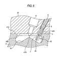
- the entirety of the sheath front end portion 3C that is, the entirety of the coil heating portion 7H of the heating coil 7 is arranged to project from the lower face 23D of the cylinder head 23 so that the coil heating 7H is positioned in its entirety in the combustion chamber 32.
- the sheath front end portion 3C and the coil heatingportion 7H of the glowplug 1 are positioned in the auxiliary combustion chamber.
- the glow plug 1 of this Embodiment 1 had such features that, when an electric voltage of 11 V was applied to the glow plug at the room temperature by using a constant voltage power source, the time needed to attain the temperature of the section of the outer surface of the sheath front end portion 3C at the position higher by 2 mm than the front end of the sheath tube reach 1,000 °C was only 3.2 seconds (refer to Figs. 6 and 7 ).
- the coil heating portion 7H i.e., the front end side portion of the front end side farther than the foremost end 9T of the electric terminal shaft 9) of the heating coil 7 is arranged in the front end portion 3C of the sheath tube 3. Therefore, unlike the related art glow plug in which, when a voltage is applied to the glow plug 1, the projecting portion as a whole of the sheath tube 3 is heated, only the section of the sheath tube 3 demanding a high temperature in the vicinity of the front end portion 3C of the sheath tube 3 is heated in this embodiment. Therefore, it is considered that a rise in the temperature of this sheath front end portion 3C comes to be attained speedily. Moreover, since the diameter of the sheath front end portion 3C is set comparatively small, the volume of the portion of the sheath tube to be heated further decreases, and it is considered that this also contributed to the speedy temperature rise.
- the outer diameter D of the sheath front end portion 3C is set to 3.5 mm.
- the coil heating portion 7H of the heating coil 7 in this Embodiment 1 is arranged in the sheath front end portion extending from its front end upward by within 15 mm, and more preferably within 11 mm.
- the outer diameter D of the sheath front end portion 3C is set smaller than 4.4 mm, and more preferably smaller than 4.0 mm, so that the volume of the portion of the sheath tube to be heated is reduced. Therefore, it is considered that the temperature rise in the sheath front end portion comes to be attained speedily.
- the glow plug 1 of Embodiment 1 is capable of having the temperature of the sheath front end portion 3C, which needs to have a high temperature, and rises speedily up to a predetermined level, so that the engine can be started in a short period of time.
- the outer diameter D of the sheath front end portion 3C is set to 3.5 mm, and the outer diameter of not smaller than 3.0 mm and more preferably not smaller than 3.5 mm is thereby secured.
- the size G (1.9 mm to be exact) of the outer diameter G of the portion of the heating coil 7 held in the sheath front end portion 3C is secured. Owing to these dimensional features, a sufficient heat generating performance of the heating coil 7 is obtained.
- the wall thickness F of the front end portion 3c of the sheath tube 3 is 0.5 mm, which is within the range of 0.3 to 0.75 mm, and within the more preferable range of 0.45 to 0.6 mm. Therefore, it is possible to secure a sufficient strength of the sheath tube 3, and a sufficiently large outer diameter G of the heating coil 7 arranged in the sheath tube 3, and to obtain a sufficient heat generating performance.
- the difference between the inner diameter E of the front end portion 3C of the sheath tube 3 and the outer diameter G of the coil heating portion 7H of the heating coil 7 is 0.6 mm, which is within the range of 0.2 mm to 1.6 mm. Namely, since this difference is as large as not smaller than 0.2 mm, the short-circuiting rarely occurs between the front endportion 3C of the sheath tube and the heating coil 7. Since the difference mentioned above is not larger than 1. 6 mm, the outer diameter G of the coil heating portion 7H of the heating coil 7 can be set sufficiently large even when the outer diameter D of the sheath front end portion 3C is small. Therefore, a necessary heat generating performance can be obtained.
- the interior of the sheath tube 3 is filled with the magnesia powder 11 with the heating coil 7 being drawn in the axial direction together with the electric terminal shaft 9. Therefore, the heating coil 7 is arranged in the front endportion 3C of the sheath tube 3 without meandering therein, and short-circuiting comes to rarely occur between the sheath front end portion 3C and the heating coil 7.
- This structure is also capable of easily increasing the outer diameter G of the heating coil 7, and setting smaller the difference between the outer diameter G of the coil heating portion 7H of the heating coil 7 and the inner diameter E of the sheath front end portion 2C.
- the outer diameter G of the coil heating portion 7H of the heating coil 7 is 1.9 mm, which is within the range of 1.5 mm to 3.0 mm. Accordingly, a sufficient heat generating performance can be obtained since the outer diameter G is not smaller than 1.5 mm, and the strength of the sheath tube 3 can be secured since the same outer diameter is not larger than 3.0 mm. Moreover, short-circuiting comes to rarely occur between the heating coil 7 and sheath tube 3.
- a space SP is formed between the metal shell 5 and the constricted portion 3G of the sheath tube 3, and the distance (or lead length) L2 in the axial direction from the end point 3FT on the front end side of the fixed portion 3F, which is radially enlarged and fixed in the metal shell 5, to the foremost end 9T of the electric terminal shaft 9 is 8.0 mm, which is not smaller than 5.0 mm. Therefore, the heat generated in the coil heating portion 7H is prevented from dissipating through the fixed portion 3F of the sheath tube 3 into the metal shell 5 to delay the temperature rise in the sheath front end portion 3C.
- the electric terminal shaft 9 has the solid rod shape of the outer diameter H of 2.0 mm, which is not smaller than 1.5 mm. Therefore, the rigidity on the base end side of the sheath tube 3 is retained to prevent the sheath tube 3 from being bent by an impact from the outside. At the time of manufacturing the glow plug 1, moreover, the defect of bending the sheath tube is also prevented at the step of the swaging treatment.
- the electric terminal shaft 9 is thick enough to suppress its resistance to a low level, and the voltage to be applied to the coil heating portion 7H is raised to raise the temperature speedily.
- Glow plugs 1 of Embodiments 2 to 5 which had substantially the same shape and construction as those of the above-described embodiment 1, and which had various coil lengths L, outer diameters (outer diameters of front end portions of sheath tubes) D of sheath front end portions 3C, normal temperature resistance values, were manufactured.
- a glow plug 1 for Comparative Example 1 in which the coil length L was enlarged, and a glow plug 1 for Comparative Example 2 in which the outer diameter D of a front end portion was enlarged were manufactured.
- the characteristics of temperature rise, the time needed to attain the temperature of 1,000 °C and the endurance cycle number of these glow plugs were examined.
- the normal temperature resistance is the resistance of the glow plug at the room temperature (of 25 ° C).
- the material of which the heating coils 7 in all of these glow plugs are made is an iron-chromium alloy wire.
- the winding pitch of the coils is 0.7 mm, and the diameter of the wires of the coils is 0.25 mm, the outer diameter G of the coils being 1.9 mm.
- the outer diameters G of the coils in Embodiment 5 and Comparative Example 2 are set to 2.5 mm and 2.6 mm, respectively.
- the wall thickness F of the front end portions 3C of the sheath tubes 3 was set to 0.5 mm but the wall thickness F in Embodiment 5 and Comparative Example 2 was set to 0.55 mm and 0.8 mm, respectively. Accordingly, the difference (E - G) between the inner diameter E of the sheath tube and the outer diameter G of the coil is 0.6 mm, but this difference in both Embodiment 5 and Comparative Example 2 is 0.8 mm.
- the normal temperature resistance value R of the glow plugs 1 were obtained by measuring the resistance values of the glow plugs 1 with a resistance meter in the environment of the normal temperature (at 25 °C).
- each glow plug The characteristics of temperature rise of each glow plug were obtained by recording temperature variation occurring while a DC voltage of 11 V was applied to each glow plug 1 to have the temperature then reach 1,000 °C as the temperature of the outer surface of the portion of the sheath tube at a distance of 2 mm higher in the axial direction than its front end 3S was measured with a thermocouple.
- the time needed to attain the temperature of 1,000 °C is the time elapsed until 1,000 °C was attained.
- the endurance tests were then conducted, in which a combination of a one-minute period for chop-supplying a DC voltage of 13.5 V to each glow plug in accordance with a duty ratio suited to the glow plug so that the temperature of the outer surface of the portion of the sheath tube 3 at 2 mm higher in the axial direction than its front end 3S became stable at 950 °C after the start of the supply of the mentioned voltage, and a one-minute period for cutting off (interrupting) the supply of the voltage was determined as one cycle, this cycle being repeated.
- the endurance cycle number was obtained by counting the cycle number recorded until the breakage of the coil occurred in this endurance test.
- the heating coil 7 is arranged in a concentrated manner in the portion of the sheath tube 3 which demands a high temperature, and which is in the vicinity of the front end 3S of the sheath tube 3, the sheath front end portion 3C is heated in a concentrated manner.
- the endurance cycle number becomes larger, i.e., the lifetime of the glow plug becomes longer as the coil length L becomes smaller. It is presumed that the reason for this resides in the following. Namely, when the coil length L is large, not only the portion of the sheath tube of 2 mm from the front end 3S thereof or close to the front end but also the portion of the sheath tube extending up to the base end section is heated. In this case, the portion of the outer surface of the sheath tube, the temperature of which becomes the highest, is the portion which is still closer to the base end, i.e., higher than the portion (which will hereinafter be referred to also as the temperature measuring point), which is at the position of 2mm from the front end 3S.
- the temperature of the portion (temperature measuring point) of the sheath tube which is at 2 mm higher than the front end 3S rises. Therefore, when an electric current is applied to the glow plug so that the temperature measuring point attains a desired temperature, the temperature of the portion at the base end becomes still higher. As a result, the heating coil 7 becomes liable to be broken.
- the coil length L is small, a distance between the portion (temperature measuring point) of the sheath tube at 2 mm from the front end 3S and the portion of the highest temperature decreases, and the difference in the temperature also decreases.
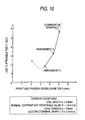
- the endurance cycle number becomes larger, i.e., the lifetime of the glow plug becomes longer as the outer diameter D of the sheath front end portion 3C becomes smaller. It is presumed that the reason for this resides in the following. Namely, when the outer diameter D is large, the area of heat dissipation becomes relatively large. Therefore, it is considered that, when the temperature of the temperature measuring point on the surface of the sheath tube is set to a desired level, the temperature of the heating coil 7 is further higher. This eventually causes the heating coil 7 to become liable to be broken. On the other hand, when the outer diameter D is small, the heat dissipation is small, so that a difference between the temperature of the temperature measuring point and the temperature of the heating coil 7 becomes small. Accordingly, it is considered that, even when an electric current is applied to the glow plug so that the temperature of the temperature measuring point becomes equal to a desired temperature, the temperature of the heating coil 7 does not become too high, and that the breakage of the wire comes to rarely occur.
- Embodiments 2 and 4 are compared with each other, it is understood that the embodiment having a lower normal temperature resistance value R has excellent characteristics of temperature rise. It is considered that the reason why the temperature of the sheath tube increases more speedily is that, when the normal temperature resistance value R is low, the making power becomes high.
- the heating coil 7 and the electric terminal shaft 9 are prepared.
- the base end portion 7K of the heating coil 7 and the small-diameter projection (although not shown) of the front end portion 9S of the electric terminal shaft 9 are connected together by welding.
- the sheath tube 3 is then prepared.
- This sheath tube 3 has a constant outer diameter of 5.15 mm.
- the heating coil 7 and the electric terminal shaft 9 are inserted from the front end portion 7S of the heating coil 7 into a hollow portion of the sheath tube 3, and the front end portion 7S of the heating coil 7 and the front end 3S of the sheath tube 3 are connected together by welding.
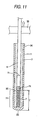
- the interior of the sheath tube 3 is filled with the magnesia powder 11 as the heating coil 7 and the electric terminal shaft 9 are drawn in the axial direction, as shown in Fig. 11 .
- the electric terminal shaft 9 is grasped by a plurality of chucks 30, which are adapted to move back and forth freely, for example, from the outer side of the axis of the electric terminal shaft 9 toward the same axis.
- the magnesia powder 11 is packed in the interior of the sheath tube 3 as the heating coil 7 and the electric terminal shaft 9 are drawn in the axial direction (upward in the drawing) of the terminal shaft 9 by those plural chucks 30.
- a seal ring (not shown) such as a rubber O-ring is arranged in an annular hollow clearance around the portion of the electric terminal shaft 9 in an opening of the base end 3K of the sheath tube 3, and the magnesia powder 11 is sealed in the hollow portion of the sheath tube 3. Since the seal ring is arranged in the opening of the base end 3K of the sheath tube 3, the occurrence of spill of the magnesia powder 11 during the swaging step, as will be described later is prevented.
- a swaging treatment is carried out by a swaging machine 70 shown in Fig. 12 .
- a swaging machine 70 a plurality of forging dies 73 arranged to surround the sheath tube 3 are supported on respectively corresponding hammers 72, and these parts are arranged in a main rotary shaft 74 and rotated in one body.
- This main rotary shaft 74 is adapted to be rotated on the inner side of a gauge 75 having a plurality of rollers 71 made of hardened steel or the like.
- the portion of the electric terminal shaft 9 projecting from the base end 3K of the sheath tube 3 is grasped by the plural chucks (not shown) which can be moved back and forth, for example, from the outer side of the axis of the terminal shaft toward the same axis.
- the swaging treatment is carried out as the electric terminal shaft 9 and the heating coil 7 are drawn in the axial direction by those plural chucks.
- the fixing metal member 5 is then prepared, and the electric terminal shaft 9 is inserted from the opening of the front end 5S into the through bore 5H, and the sheath tube 3 is then press-fitted and fixed in the fixing metal member.
- the O-ring 15 is thereafter fitted in the countersunk section 5Z formed in the base end portion 5K of the fixing metal member 5, and the insulating bush 17 is further fitted therein.
- the ferrule 19 is further fixed on the insulatingbushby caulking.
- the nut 21 is fixed on the ferrule.
- the magnesia powder 11 is packed in the sheath tube 3 at the insulating powder filling step as the base end portion 7K of the heating coil 7 as well as the electric terminal shaft 9 is drawn in the axial direction with the front endportion 7s of the heating coil 7 being fixed on the front end 3S of the sheath tube 3 by welding. Therefore, the heating coil 7, to which a tensile force is exerted, is arranged in the sheath tube 3 along the axis without meandering therein, and a clearance can be secured reliably between the sheath tube 3 and heating coil 7. Accordingly, even when the diameter of the sheath tube 3 is reduced at a later swaging step, short-circuiting comes to rarely occur between these two parts.
- the heating coil 7 is arranged such that the front end side portion 7H of the heating coil 7 on the front end side farther than the foremost end 9T of the electric terminal shaft 9, that is, the coil heating portion 7H may take a coil length L not more than 15 mm in the axial direction from the front end 3S of the sheath tube 3. Therefore, when a voltage is applied to the glow plug, the section of the sheath tube 3 in the vicinity of the front end portion 3C comes to be heated in a concentrated manner without heating the portion as a whole of the sheath tube 3 projecting from the metal shell 5. This enables the temperature of the sheath front end portion 3C to be speedily raised as compared with that in the related art glow plug. Accordingly, when the glow plug 1 manufactured in the above-described manner is used for preheating a diesel engine, the engine can be started in a short period of time.
- the sheath tube 3 filled with the magnesia powder 11 is subjected to a swaging treatment at the swaging step as the base end portion 7K of the heating coil 7 is drawn in the axial direction. Therefore, even when the diameter of the sheath tube 3 is reduced, the heating coil 7 is arranged in the sheath tube 3 (or its front end portion 3C) without causing the coil to meander therein. Accordingly, short-circuiting rarely occurs between the sheath front end portion 3c and the heating coil 7.
- an iron-chromium alloy is used as the material for the heating coil 7 in each of the above embodiments.
- the heating coil may also be formed by using some other material, such as a nickel-chromium alloy.
Landscapes
- Engineering & Computer Science (AREA)
- Chemical & Material Sciences (AREA)
- Combustion & Propulsion (AREA)
- Mechanical Engineering (AREA)
- General Engineering & Computer Science (AREA)
- Resistance Heating (AREA)
Description
- The present invention relates to a glow plug used to preheat a diesel engine and for other purposes, a structure for mounting the glow plug, and a process for manufacturing the glow plug.
- Various modes of glow plugs used to preheat a diesel engine and for other purposes have heretofore been known in the related art. A
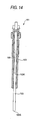
glowplug 101, a general view and a longitudinal sectional view of which are shown inFig. 13 andFig. 14 , respectively, is included as an example of the known glow plugs. Thisglow plug 101 is provided with acylindrical sheath tube 103 closed at itsfront end 103S and opened at itsbase end 103K, and acylindrical metal shell 105 covering thesheath tube 103 on the side of thebase end 103K. Of these parts, thesheath tube 103 projects, at its portion having a length of about 36 mm from itsfront end 103S, from the front end of themetal shell 105, and an outer diameter of this portion of the sheath tube is at a uniform value of 5.0 mm. - Inside of the
sheath tube 103, aheating coil 107 is arranged along the axis of thesheath tube 103, as shown in the partial enlarged sectional view ofFig. 15 . Afront end portion 107S of thisheating coil 107 is electrically connected with thefront end 103S of thesheath tube 103. Into the portion of thesheath tube 103 on the side of thebase end 103K, there is inserted a part of a rod-shapedelectric terminal shaft 109 along the axis of thesheath tube 103. Afront end portion 109S of theelectric terminal shaft 109 is electrically connected with abase end portion 107K of theheating coil 107 in the vicinity of the front end of themetal shell 105. Furthermore, the interior of thesheath tube 103 is filled withmagnesia powder 111 or insulating powder. - When
such glow plug 101 is fixed to a cylinder block of a diesel engine with a voltage being applied to theelectric terminal shaft 109 from a vehicle-mounted battery as a power source, an electric current flows from theelectric terminal shaft 109 to the cylinder head (or an engine block) through theheating coil 107,sheath tube 103 andmetal shell 105. As a result, a high current flows to theheating coil 107 to raise its temperature, so that thesheath tube 103 is heated substantially as a whole at its portion projecting from themetal shell 105. - However, this
glow plug 101 of the related art takes time to be heated to a temperature needed for preheating the diesel engine. For example, it takes around 15 seconds to heat up to about 1,000 °C the portion of thesheath tube 103 in the vicinity of thefront end 103S. - The present invention has been made in view of such circumstances, and has an object to provide a glow plug, the temperature of which can be speedily raised, a structure for mounting the glow plug, and a suitable process for manufacturing the glow plug.
-
US 4,549,071 , on which the precharacterizing portions of the independent claims are based, discloses a glow plug comprising a first helical heating member and a second helical heating member connected to the first heating member, and a sheath enclosing the first and second heating members. The outer diameter of the sheath is 5.0mm. - According to the present invention, there is provided a glow plug and a process for manufacturing a glow plug as defined in the independent claims.
- In the related art glow plug, the heating coil was arranged to extend axially over substantially the whole of that portion of the sheath tube, which projects from the metal shell. Moreover, the outer diameter of the sheath tube was comparatively large. Therefore, it took long time to raise the temperature of the sheath tube up to a predetermined level.
- The coil of the invention is adapted not to heat the sheath tube as a whole with the coil but to heat only the portion of the sheath tube in the vicinity of the front end portion with the front end side portion of the coil, so that the temperature rise is attained speedily as far as the front end portion of the sheath tube is concerned. Moreover, the outer diameter of the front end portion of the sheath tube is set smaller so that the volume to be heated is reduced to accelerate the temperature rise more speedily. In short, according to the present invention, the temperature of the glow plug can be raised speedily as compared with that of a related art glow plug. Therefore, when the glow plug according to the present invention is used to preheat a diesel engine, it becomes possible to start the engine in a short period of time. For example, when a voltage of 11 V is applied to the glow plug at the room temperature, the time needed for the temperature of the portion of the outer surface of the sheath tube at the position of 2 mm in the axial direction from the front end to reach 1, 000 °C is not longer than 5 seconds.
- Since only that portion in the vicinity of the front end portion of the sheath which demands a high temperature (for example, 1,000 °C) is heated, moreover, the temperature of this portion rises speedily, and, after the temperature becomes high, this high level of the temperature can be controlled and maintained. Therefore, the performance of the glow plug can rather be improved as compared with that of the related art glow plug in which, when an electric current is applied thereto until the front end portion of the sheath tube attains a desired temperature, the temperature of the portion (for example, the portion which is slightly closer to the base end side of the sheath tube than to the front end portion, etc.) of the sheath tube and the temperature of which rises more easily than that of the front end portion is liable to become further high.
- With the invention the coil made of only the heating coil is used as the coil, and the portion of the heating coil on the front end side farther than the foremost end of the lead member has the coil length L of not more than 11 mm from the front end of the sheath tube. The reason is that the temperature rise in the front end portion of the sheath tube can be attained speedily. For example, when a voltage of 11 V is applied to the glow plug at the room temperature, the time needed for the temperature of the portion of the outer surface of the sheath tube at the position of 2 mm in the axial direction from the front end to reach 1,000 °C is not longer than 3.5 seconds.
- On the other hand, it is preferable that the axial length of the heating coil on the front end side farther than the foremost end of the lead member is set not smaller than 4 mm when the heating performance is taken into consideration.
- Here, the connection mode between the coil base end portion and the lead member is not especially limited. As this connection mode, there can be enumerated: a mode of winding and welding the coil closely on the outer circumference of the front end portion of the lead member; a mode of inserting a portion having a coil closely wound thereon into a recess formed in the axial direction of the lead member thereby to bond or weld the portion to the lead member; and a mode of bonding the base end of the coil to the foremost end (or the front end face) of a seed member.
- The means for solving the problem also resides in the same glow plug as described above, in which the outer diameter of the sheath front end portion be preferably set to not smaller than 3.0 mm. The reason resides in the following. When the outer diameter of the front end portion of the sheath tube is set too small, the outer diameter of the coil is necessarily set small correspondingly, so that a sufficient heating performance cannot be obtained in some cases.
- It is further desirable that the outer diameter of the sheath front end portion be set to 3.5 mm to 4.4 mm. The reason resides in the following. Setting the outer diameter not smaller than 3.5 mm enables the coil arranged in the inner section of the sheath front end portion to be enlarged, and a sufficient heating performance to be secured, and setting the outer diameter not larger than 4.4 mm enables a temperature rise in the sheath front end portion to be attained further speedily.
- In the glow plug, moreover, from the end point of the axial front end side of a fixed portion, as fixed directly or indirectly through another member on the metal shell, of the sheath tube, to the foremost end of the lead member, a distance not smaller than 5 mm is kept toward the axial front end side.
- The heat generated at the coil dissipates partially into the metal shell through the fixed portion. In this glow plug, however, there is spaced the distance between the fixed portion of the metal shell and the front end side portion of the coil on the front end side farther than the foremost end of the lead member. As compared with the structure having the short distance, therefore, the heat to dissipate into the metal shell can be relatively reduced to prevent the front end side portion of the coil and accordingly the sheath front end portion enclosing it from being delayed in the temperature rise.
- Here, the fixed portion implies that portion of the sheath tube which is fixed on the metal shell. In case the base end side of the sheath tube is press-fitted, additionally fastened after inserted, or fixed without any solder in the through bore formed in the metal shell, the fixed portion is the portion which is pressed into the through bore of the metal shell. In case the base end side of the sheath tube is inserted into the through bore formed in the metal shell so that the sheath tube and the metal shell are fixed indirectly through the solder, on the other hand, the fixed portion is the portion of the sheath tube, in which the solder resides between itself and the metal shell.
- Moreover, it is preferable for the glow plug that a distance not smaller than 8 mm is spaced toward the front end side in the axial direction from the end point of the front end side of the fixed portion in the axial direction to the foremost end of the lead member.
- With the distance not smaller than 8 mm between the end point of the axial front end side of the fixed portion and the foremost end of the
lead member 9, the heat to dissipate into the metal shell can be sufficiently reduced to prevent the resultant delay in the temperature rise sufficiently. - In any of the glow plugs described above, the lead member has a solid rod shape having an outer diameter not smaller than 1.5 mm.
- If the lead member is thin, the sheath tube is lowered in its rigidity on its base end side so that it is liable to be bent by an impact from the outside. At the manufacturing time, moreover, the sheath tube is liable to be bent at the swaging step so that the yield drops easily. Because of the thin lead member, moreover, the resistance of the lead member itself is apt to rise, and the voltage to be applied to the coil is lowered to reduce the heat generated by the coil, thereby to delay the temperature rise.
- In the glow plug of the invention, on the other hand,
the lead member used is the solid rod having an outer diameter not smaller than 1.5 mm. Therefore, the sheath tube is enhanced in its rigidity on the base end side so that it is prevented from being bent. Moreover, the yield at the swaging step is also enhanced. The resistance owned by the lead member can be suppressed to accelerate the temperature rise of the glow plug relatively. - In the glow plug, moreover, it is advisable that the difference between the outer diameter of the lead member and the inner diameter of the sheath tube is not smaller than 0.2 mm.
- The sheath tube is highly rigid on its base end side and is reluctant to bend. Therefore, the larger outer diameter of the lead member is the more preferred. In order to secure the insulation from the sheath tube, however, it is preferable that the diameter difference be secured at least within 0.2 mm.
- With the invention the wall thickness of the front end portion of the sheath tube is 0.3 mm to 0.75 mm.
- When the wall thickness of the front end portion of the sheath tube is set smaller than 0.3 mm, the strength of the sheath tube becomes insufficient so that it is liable to be broken by the impact of a fall. On the other hand, when the wall thickness of the front end portion of the sheath tube is set as large as not smaller than 0.75 mm, the inner diameter of the front end portion of the sheath tube becomes excessively small since the outer diameter of the front end portion of the sheath tube is set small. As a result, the outer diameter of the coil becomes unable to be secured sufficiently, so that a necessary heating performance of the coil cannot be obtained.
- The glow plug according to the present invention has a wall thickness of the sheath front end portion of 0.3 mm to 0.75 mm. Therefore, it is possible to secure the strength of the sheath tube and to enlarge the outer diameter of the coil disposed in the sheath front end portion relatively, thereby to obtain a sufficient heating performance of the coil.
- It is further preferable that the wall thickness of the sheath front end portion be 0.45 mm to 0.6 mm. The reason resides in the possibility of securing the strength of the sheath tube more reliably and enlarging sufficiently the outer diameter of the coil arranged in the sheath front end portion, thereby to obtain a more satisfactory heating performance.
- The means for solving the problem further resides in any one of these glow plugs, in which a difference between the inner diameter of the front end portion of the sheath tube and the outer diameter of the coil is 0.2 mm to 1.6 mm.
- When the difference between the inner diameter of the sheath front end portion and the outer diameter of the front end side portion of the coil is smaller than 0.2 mm, short-circuiting becomes liable to occur between the sheath front end portion and coil. On the other hand, when this difference becomes larger than 1. 6 mm, the coil becomes liable to meander in the sheath front end portion, and short-circuiting likewise becomes liable to occur. Moreover, since the outer diameter of the sheath front end portion is set small, the outer diameter of the front end side portion of the coil becomes too small to obtain a necessary heating performance in some cases.
- On the other hand, according to the present invention, the difference between the inner diameter of the sheath front end portion and the outer diameter of the front end side portion of the coil is within the range of 0.2 mm to 1.6 mm. Therefore, the short-circuiting rarely occurs between the front end portion of the sheath tube and the coil. Even when the outer diameter of the sheath tube is small, a satisfactorily large outer diameter of the coil can be secured, so that a necessary heating performance can be obtained.
- With the manufacturing process of the invention the interior of the sheath tube is filled with insulating powder with the coil front end portion being connected to the front end of the sheath tube and with the coil base end portion being drawn in the axial direction.
- The interior of the sheath tube (its front end portion) is filled with insulating powder with the coil front end portion being connected to the front end of the sheath tube and with the coil being drawn in the axial direction. In such a glow plug, the coil is retained in the drawn state, so that the front end side portion of the coil farther than the foremost end of the lead member is arranged to extend straight along the axis without meandering. Therefore, short-circuiting rarely occurs between the sheath front end portion and the coil. Since the front end side portion of the coil does not meander, the outer diameter of the front end side portion of the coil is easily diametrically enlarged, and the difference between the outer diameter of the front end side portion of the coil and the inner diameter of the sheath front end portion is easily reduced.
- The means for solving the problem further resides in any one of these glow plugs, in which the outer diameter of the front end side portion of the coil be preferably set to 1.5 mm to 3.0 mm.
- When the outer diameter of the front end side portion of the coil is smaller than 1.5 mm, a sufficient heating performance may not be obtained in some cases. When the outer diameter of the coil exceeds 3.0 mm, the wall thickness of the sheath front end portion is necessarily reduced since the outer diameter of the sheath tube is limited, and this causes the strength of the sheath tube to become insufficient in some cases. As the outer diameter of the coil is increased, the distance between the coil and the inner surface of the sheath front end portion becomes smaller, and short-circuiting becomes liable to occur between the coil and the sheath front end portion.
- On the other hand, when the outer diameter of the front end side portion of the coil is set not smaller than 1.5 mm, a sufficient heating performance can be obtained. When this diameter is set not larger than 3.0 mm, the strength of the sheath tube can be secured, and short-circuiting comes to rarely occur between the coil and the sheath front end portion.
- The outer diameter of the front end side portion of the coil shall indicate the outermost one taken in a longitudinal sectional view including the center axis of the sheath tube.
- The means for solving the problem further resides in any one of the above-described glow plugs, which is preferably so formed that, when a voltage of 11 V is applied to the plug at the room temperature, the time needed to have the temperature of the portion of the outer surface of the sheath tube, which is higher in the axial direction than the front end by 2 mm reach 1,000 °C is not longer than 5 seconds. The reason is that, when such a glow plug is used for preheating a diesel engine or for other purposes, the time needed to attain such a necessary temperature can be reduced.
- In this plug, it is further preferable that the time needed to attain the temperature of 1,000 °C be not longer than 3.5 seconds. The reason is that the time needed to attain the temperature necessary for preheating the engine can be further reduced.
- The means for solving the problem further resides in any one of the above-described glow plugs, which has a glow plug mounting structure for mounting a glow plug, with the front end side of the sheath tube projecting into the combustion chamber of a diesel engine, and the sheath front end portion projects into the combustion chamber with the front end side portion of the coil being positioned as a whole in the combustion chamber.
- Generally in the diesel engine, the sheath tube of the glow plug projects on its front end side into the combustion chamber. Therefore, a mounting hole is so formed in the cylinder head at to lead to the combustion chamber, and the glow plug is mounted in that mounting hole. Depending upon the projection size of the sheath tube into the combustion chamber, the coil may be arranged partially at its front end side portion in the mounting hole. In this case, the heat generated at the front end side portion of the coil may be transferred to the cylinder head. Therefore, the heat generating characteristics of the sheath front end portion may not be exhibited in the combustion chamber.
- According to the glow plug mounting structure of the invention, on the contrary, the front end side portion of the coil is so mounted in its entirety as to project without being enclosed by the cylinder head. Therefore, the heat to dissipate into the cylinder head can be suppressed to raise the temperature speedily. Moreover, most of the heat generated at the front end side portion of the coil can be utilized for heating the fuel in the combustion chamber, thereby to provide an advantage that the ignition can be efficiently assisted.
- Here, the combustion chamber covers not only the main combustion chamber but also an auxiliary combustion chamber (e.g., a swirl combustion chamber or a precombustion chamber).
- Moreover, the invention is especially preferred, it applied to a direct injection type diesel engine, which has such mounting structure and in which a combustion chamber is recessed in the piston. In this engine, the recessed combustion chamber in the piston is liable to limits the depth of the combustion chamber. Therefore, there is also limited the projection size of the sheath heating portion of the sheath tube of the glow plug, which is projected into the combustion chamber. In the plug of the invention, the heat is generated in a concentrated manner at the sheath front end portion of the sheath tube so that the fuel can be efficiently heated to assist the ignition efficiently even with the small projection size.
- According to the manufacturing process of the invention, at the insulating powder filling step, the sheath tube being filled with the insulating powder, as the lead member and the coil base end portion of the coil connected to the lead member are drawn in the axial direction with the coil front end portion of the coil being connected to the front end of the sheath tube.
- When the insulating powder is thus packed in the sheath tube, the coil is arranged to extend straight along the axis of the sheath tube without meandering in the sheath tube. Therefore, short-circuiting rarely occurs between the sheath tube and the coil.
- The means for solving the problem also resides in the same process for manufacturing a glow plug as described above, and the process may further comprise the swaging step of subjecting the sheath tube, which was filled with the insulating powder during the insulating powder filling step, to a swaging treatment as the lead member and the base end portion of the coil connected to the lead member are drawn in the axial direction.
- According to the invention, the sheath tube filled with the insulating powder is subjected to a swaging treatment at the swaging step as the lead member and the base end portion of the coil connected to the lead member are drawn in the axial direction.
- Therefore, even when the sheath tube is made to a smaller diameter, the coil is arranged straight along the axis without meandering in the sheath tube. Accordingly, short-circuiting comes to rarely occur between the sheath front end portion of the sheath tube and the heating coil.
- The means for solving the problem also resides in the same process for manufacturing a glow plug as described above, in which the coil is arranged after the swaging step was carried out at the insulating material filling step, in such a manner that the front end side portion of the coil farther than the foremost end of the lead member has a coil length L not larger than 15 mm in the axial direction from the front end of the sheath tube, and in which the outer diameter of the front end side portion of the sheath tube enclosing the front end side portion of the coil is set not larger than 4.4 mm at the swaging step.
- According to the invention, the coil is arranged after the swaging step was carried out in the insulating powder filling step, in such a manner that the front end side portion of the coil has a coil length L not larger than 15 mm in the axial direction from the front end of the sheath tube.
- At the swaging step, moreover, the outer diameter of the sheath front end portion is set not larger than 4.4 mm.
- When the coil is thus arranged at its front end side portion in the sheath front end portion with, moreover, the diameter of the sheath front end portion reduced, only the sheath front end portion of a small volume is heated in a concentrated manner without heating the sheath tube as a whole. Therefore, the temperature of this sheath front end portion can be raised speedily as compared with that of the corresponding portion formed in the related art glow plug manufacturing process. Consequently, when the glow plug thus manufactured is used to preheat the diesel engine, it becomes possible to start the engine in a short period of time.
- It is more preferable that the front end side portion of the heating coil farther than the foremost end of the lead member has the coil length not larger than 11 mm from the front end of the sheath tube. The reason is that there can be manufactured the glow plug capable of attaining a temperature rise speedily, i.e., the glow plug in which, for example, when a voltage of 11 V is applied thereto at the room temperature, the time needed to have the portion of the outer surface of the sheath tube higher in the axial direction than the front end of the sheath tube by 2 mm reach 1,000 °C is not longer than 5 seconds.
- In the swaging treatment, it is preferable that the outer diameter of the sheath front end portion be set not smaller than 3.0 mm. The reason is that, when the outer diameter of the sheath front end portion of the sheath tube is set too small, the outer diameter of the coil is necessarily set small correspondingly, so that a sufficient heating performance cannot be obtained in some cases.
-
-
Fig. 1 is a side view showing an outer shape of a glow plug in a mode of embodiment. -
Fig. 2 is a longitudinal sectional view of the glow plug in the mode of embodiment. -
Fig. 3 is a partially enlarged sectional view of the portion of the glow plug in the mode of embodiment in the vicinity of a sheath tube. -
Fig. 4 is an explanatory view of the state, in which the glow plug in the mode of embodiment is mounted in a direct injection type diesel engine. -
Fig. 5 is a partially enlarged explanatory view for explaining the relation between the coil of the glow plug and a combustion chamber in the state shown inFig. 4 . -
Fig. 6 is an explanatory diagram tabulating the sizes and characteristics of the glow plugs in the individual embodiments and comparative examples. -
Fig. 7 is an explanatory diagram tabulating the sizes and characteristics of the glow plugs in the individual embodiments and comparative examples including the additional embodiments and comparative examples. -
Fig. 8 is a graph presenting the temperature rising characteristics of the glow plugs in the individual embodiments. -
Fig. 9 is a graph presenting relations between a coil length L and an attainable time T of 1,000 °C of the characteristics of the embodiments and comparative examples shown inFigs. 7 and8 . -
Fig. 10 is a graph presenting relations between a front end portion outer diameter D and the attainable time of 1, 000 °C of the characteristics of the embodiments and comparative examples shown inFigs. 7 and8 . -
Fig. 4 is an explanatory view showing an insulating powder filling step of packing magnesia powder in a sheath tube in the process for manufacturing the glow plug in a mode of embodiment. -
Fig. 5 is an explanatory view showing an essential portion of a swaging machine for carrying out a swaging treatment in the process for manufacturing the glow plug in a mode of embodiment. -
Fig. 13 is a side view showing an outer shape of a glow plug in the related art. -
Fig. 14 is a longitudinal sectional view of the glow plug in the related art. -
Fig. 15 is a partially enlarged sectional view of the portion of the glow plug in the related art mode in the vicinity of the sheath tube. - In Reference Numerals and Signs: 1...GLOW PLUG; 3...SHEATH TUBE; 3C...SHEATH FRONT END PORTION; 3S ... FRONT END (OF THE SHEATH TUBE); 3K...BASE END (OF THE SHEATH TUBE); 3F...FIXED PORTION (OF THE SHEATH TUBE); 3FT...END POINT (ON THE FRONT END SIDE OF THE FIXED PORTION); 3G...CONSTRICTED PORTION; 5...METAL SHELL; 7...HEATING COIL; 7S...COIL FRONT END PORTION; 7K...COIL BASE END PORTION; 7H...FRONT END SIDE PORTION (ON THE FRONT END SIDE OF THE COIL FARTHER THAN THE FOREMOST END OF THE LEAD MEMBER) ; 9...ELECTRIC TERMINAL SHAFT (LEAD MEMBER); 9T...FOREMOST END (OF THE ELECTRIC TERMINAL SHAFT) ; 11...MAGNESIA POWDER (INSULATING POWDER) ; 70...SWAGING MACHINE; L...COIL LENGTH; L2...LEAD LENGTH; D...OUTER DIAMETER (OF THE SHEATH FRONT END PORTION) ; E...INNER DIAMETER (OF THE SHEATH TUBE) ; AND H...OUTER DIAMETER (OF THE ELECTRIC TERMINAL SHAFT).
- The modes of embodiment of the present invention will now be described with reference to the drawings. Each of the following sizes has relation to Embodiment 1 (refer to
Fig. 6 andFig. 7 ) of these modes of embodiment. - Concerning the
glow plug 1 of this mode of embodiment, a general view is shown inFig. 1 , a longitudinal sectional view inFig. 2 , and a partially enlarged sectional view of the portion in the vicinity of asheath tube 3 inFig. 3 . Thisglow plug 1 is provided with acylindrical sheath tube 3 closed at its front end (closed portion) 3S and opened at itsbase end 3K (open portion), and acylindrical metal shell 5 covering the portion of thissheath tube 3 on the side of thebase end 3K. - Of these parts, the
sheath tube 3 is fixed and retained at its portion on the side of itsbase end 3K by press-fitting a later-described bulgingfixed portion 3F in a throughbore 5H of themetal shell 5, and projects at its portion extending from itsfront end 3S by about 36 mm, from afront end 5S of themetal shell 5. An outer diameter D of this projectingconstricted portion 3G is at a uniform value of D = 3.5 mm, and an inner diameter E of the same is at a uniform value of E = 2.5 mm. Accordingly, a wall thickness F of this portion is at a uniform value of F = 0.5 mm. At the portion of thesheath tube 3 which is positioned in the throughbore 5H of themetal shell 5, the outer diameter and inner diameter are enlarged to have the bulging fixedportion 3F having a larger diameter than that of the front end side. At the fixedportion 3F in the vicinity of thebase end 3K, the outer diameter is 4.4 mm, and the inner diameter 3.3 mm. In this mode of embodiment, an end point 3FT of the fixedportion 3F on the front end side (on the lower side of the Drawings) is positioned on the base end side (on the upper side of the Drawings) farther than thefront end 5S of themetal shell 5, thereby to form a ring-shaped apace SP between the throughbore 5H and theconstricted portion 3G. - In the interior of the
sheath tube 3, aheating coil 7 adapted to generate heat when an electric current is supplied to the glow plug is arranged along its axis, as shown inFig. 3 . Thisheating coil 7 is provided with abase end portion 7K and afront end portion 7S. The coilbase end portion 7K is used to be connected to an electricterminal shaft 9, as will be hereinafter, and to make a portion which does not generate heat even when energized. Of thisheating coil 7, on the other hand, the portion of the front end side (on the lower side of the Drawings) farther than theforemost end 9T of the electricterminal shaft 9 is formed by turning a conductor in a coil shape. Of thisheating coil 7, the frontend side portion 7H (as will be called the "coil heating portion 7H") is arranged in a sheathfront end portion 3C, specifically, in the portion of a distance L = 11 mm from thefront end 3S of the outer circumference of thesheath tube 3 to theforemost end 9T. In short, thecoil heating portion 7H has a size of the distance L = 11 mm, as metered from thefront end 3S of the outer circumference of thesheath tube 3, in the axial direction. - The
front end portion 7S of theheating coil 7 is electrically connected to thefront end 3S of thesheath tube 3 by welding. Thisheating coil 7 is formed of an iron-chromium alloy wire. A nickel-chromium alloy wire can also be used. Thisheating coil 7 has a diameter of the wire of 0.25 mm, and an outer diameter G of 1.9 mm, a winding pitch of 0.7 mm and the number of turns of the wire of 10. Therefore, a difference between an inner diameter E of the sheathfront end portion 3C and the outer diameter G of theheating coil 7 is 0.6 mm. The distance L mentioned above will also hereinafter be referred to simply as a coil length L. - In the interior of the
sheath tube 3, a lead member, in concrete terms, the solid rod typeelectric terminal shaft 9 is inserted along the axis of thesheath tube 3. Afront end portion 9S of the electricterminal shaft 9 has a stepped constricted projection (although not shown) and is electrically connected with thebase end portion 7K of theheating coil 7 by welding. The electricterminal shaft 9 projects from abase end portion 5K of themetal shell 5 through themetal shell 5 to the base end side (to the upper side of the Drawings). A male thread is formed in the outer circumference of this projecting portion to form amale thread portion 9N. In this mode of embodiment, the foremost end (corresponding to the front end face in this mode of embodiment) of that small projection provides theforemost end 9T of the electricterminal shaft 9. - Moreover, the interior of the
sheath tube 3 is filled with magnesia powder (insulating powder) 11. To be concrete, themagnesia powder 11 is packed in thesheath tube 3 with thefront end portion 7S of theheating coil 7 being connected to thefront end 3S of thesheath tube 3 and with thebase end portion 7K of theheating coil 7 and the electricterminal shaft 9 being drawn in the axial direction to the base end side (upward of the Drawings). - The
metal shell 5 is provided on the side of itsbase end portion 5K with a cross-sectionally hexagonaltool engaging region 5R, with which a tool such as a wrench is to be engaged when theglow plug 1 is fixed to a diesel engine, and on the immediately front side of thetool engaging region 5R with a glow plug fixing threadedsection 5T. - The
base end portion 5K of themetal shell 5 is provided with acountersunk section 5Z in the throughbore 5H. In thiscountersunk section 5Z, there are fitted a rubber O-ring 15 and an insulatingnylon bush 17 fitted around the electricterminal shaft 9. Moreover, aferrule 19 for preventing the insulatingbush 17 from coming off is mounted on the insulatingbush 17. Theferrule 19 is fixed to the electricterminal shaft 9 by caulkedportions 19C formed on the outer circumference of theferule 19. The surface of the electricterminal shaft 9, to which theferrule 19 is opposed, is provided with aknurled portion 9R, the outer circumference of which is knurled so as to enhance the caulk-bonding power. Anut 21 is a part for fixing a power supplying electric cable to the electricterminal shaft 9. - Here will be described (refer to
Fig. 4 andFig. 5 ) the power supply to the glow plug and the characteristics at the power supply when theglow plug 1 is mounted in adiesel engine 20. - This
diesel engine 10 is composed of: acylinder block 21 having acylinder 22; acylinder head 23 for closing the cylinder; and apiston 31 moving reciprocally upward and downward in thecylinder 22. Thisdiesel engine 20 is a direct injection type diesel engine. Acombustion chamber 32 is formed in the recessedupper face 31U of thepiston 31, and a fuel is atomized from anozzle 41N at the front end of afuel atomizing device 41. Theglow plug 1 is fixed in a mountinghole 23H, which is formed in thecylinder head 23 of thediesel engine 20, by using the fitting threadedsection 5T of themetal shell 5. As a result, the sheathfront end portion 3C housing theheating coil 7 is positioned in thecombustion chamber 32 of theengine 20. Specifically, the entirety of the sheathfront end portion 3C, that is, the entirety of thecoil heating portion 7H of theheating coil 7 is arranged to project from thelower face 23D of thecylinder head 23 so that thecoil heating 7H is positioned in its entirety in thecombustion chamber 32. - In case the invention is applied to the engine of the type having amain combustion chamber and an auxiliary combustion chamber unlike this embodiment, the sheath
front end portion 3C and thecoil heatingportion 7H of theglowplug 1 are positioned in the auxiliary combustion chamber. - When a voltage is applied from a vehicle-mounting battery as a power source, to the electric
terminal shaft 9, an electric current flows from the electricterminal shaft 9 through theheating coil 7, thesheath tube 3 and themetal shell 5 to thecylinder head 23. As a result, a large current flows to theheating coil 7 in the inner portion of thesheath tube 3, so that the temperature of thefront end portion 3C rises speedily. After the temperature of the sheathfront end portion 3C rises to a predetermined level (for example, 1,000 °C), the temperature of theheating coil 7 is maintained at a substantially predetermined level by chop-controlling the applied voltage. By atomizing the fuel from thenozzle 41 of thefuel atomizing device 41 while the sheathfront end portion 3C being thus heated, the ignition of the fuel is assisted so that the engine is started by the combustion of the fuel. - It was ascertained that the
glow plug 1 of thisEmbodiment 1 had such features that, when an electric voltage of 11 V was applied to the glow plug at the room temperature by using a constant voltage power source, the time needed to attain the temperature of the section of the outer surface of the sheathfront end portion 3C at the position higher by 2 mm than the front end of the sheath tube reach 1,000 °C was only 3.2 seconds (refer toFigs. 6 and7 ). - In such a
glow plug 1, thecoil heating portion 7H (i.e., the front end side portion of the front end side farther than theforemost end 9T of the electric terminal shaft 9) of theheating coil 7 is arranged in thefront end portion 3C of thesheath tube 3. Therefore, unlike the related art glow plug in which, when a voltage is applied to theglow plug 1, the projecting portion as a whole of thesheath tube 3 is heated, only the section of thesheath tube 3 demanding a high temperature in the vicinity of thefront end portion 3C of thesheath tube 3 is heated in this embodiment. Therefore, it is considered that a rise in the temperature of this sheathfront end portion 3C comes to be attained speedily. Moreover, since the diameter of the sheathfront end portion 3C is set comparatively small, the volume of the portion of the sheath tube to be heated further decreases, and it is considered that this also contributed to the speedy temperature rise. - To be concrete, the
coil heating portion 7H of theheating coil 7 in thisEmbodiment 1 is arranged in the sheathfront end portion 3C which extends from the front end of thesheath tube 3 to the portion of L = 11 mm. In short, the coil length of thecoil heating portion 7H is L = 11 mm. Moreover, the outer diameter D of the sheathfront end portion 3C is set to 3.5 mm. Namely, thecoil heating portion 7H of theheating coil 7 in thisEmbodiment 1 is arranged in the sheath front end portion extending from its front end upward by within 15 mm, and more preferably within 11 mm. Moreover, the outer diameter D of the sheathfront end portion 3C is set smaller than 4.4 mm, and more preferably smaller than 4.0 mm, so that the volume of the portion of the sheath tube to be heated is reduced. Therefore, it is considered that the temperature rise in the sheath front end portion comes to be attained speedily. As compared with the related art glow plug, theglow plug 1 ofEmbodiment 1 is capable of having the temperature of the sheathfront end portion 3C, which needs to have a high temperature, and rises speedily up to a predetermined level, so that the engine can be started in a short period of time. - In this
Embodiment 1, thecoil heating portion 7H of theheating coil 7 is arranged in the portion of thesheath tube 3, which extends from its front end to the portion higher by L=11 mm than the sheath front end, as mentioned above, and a length not smaller than L = 4 mm is secured. Moreover, the outer diameter D of the sheathfront end portion 3C is set to 3.5 mm, and the outer diameter of not smaller than 3.0 mm and more preferably not smaller than 3.5 mm is thereby secured. Thus, the size G (1.9 mm to be exact) of the outer diameter G of the portion of theheating coil 7 held in the sheathfront end portion 3C is secured. Owing to these dimensional features, a sufficient heat generating performance of theheating coil 7 is obtained. - In
Embodiment 1, the wall thickness F of the front end portion 3c of thesheath tube 3 is 0.5 mm, which is within the range of 0.3 to 0.75 mm, and within the more preferable range of 0.45 to 0.6 mm. Therefore, it is possible to secure a sufficient strength of thesheath tube 3, and a sufficiently large outer diameter G of theheating coil 7 arranged in thesheath tube 3, and to obtain a sufficient heat generating performance. - The difference between the inner diameter E of the
front end portion 3C of thesheath tube 3 and the outer diameter G of thecoil heating portion 7H of theheating coil 7 is 0.6 mm, which is within the range of 0.2 mm to 1.6 mm. Namely, since this difference is as large as not smaller than 0.2 mm, the short-circuiting rarely occurs between thefront endportion 3C of the sheath tube and theheating coil 7. Since the difference mentioned above is not larger than 1. 6 mm, the outer diameter G of thecoil heating portion 7H of theheating coil 7 can be set sufficiently large even when the outer diameter D of the sheathfront end portion 3C is small. Therefore, a necessary heat generating performance can be obtained. - The interior of the
sheath tube 3 is filled with themagnesia powder 11 with theheating coil 7 being drawn in the axial direction together with the electricterminal shaft 9. Therefore, theheating coil 7 is arranged in thefront endportion 3C of thesheath tube 3 without meandering therein, and short-circuiting comes to rarely occur between the sheathfront end portion 3C and theheating coil 7. This structure is also capable of easily increasing the outer diameter G of theheating coil 7, and setting smaller the difference between the outer diameter G of thecoil heating portion 7H of theheating coil 7 and the inner diameter E of the sheath front end portion 2C. - In this
Embodiment 1, the outer diameter G of thecoil heating portion 7H of theheating coil 7 is 1.9 mm, which is within the range of 1.5 mm to 3.0 mm. Accordingly, a sufficient heat generating performance can be obtained since the outer diameter G is not smaller than 1.5 mm, and the strength of thesheath tube 3 can be secured since the same outer diameter is not larger than 3.0 mm. Moreover, short-circuiting comes to rarely occur between theheating coil 7 andsheath tube 3. - Moreover, a space SP is formed between the
metal shell 5 and theconstricted portion 3G of thesheath tube 3, and the distance (or lead length) L2 in the axial direction from the end point 3FT on the front end side of the fixedportion 3F, which is radially enlarged and fixed in themetal shell 5, to theforemost end 9T of the electricterminal shaft 9 is 8.0 mm, which is not smaller than 5.0 mm. Therefore, the heat generated in thecoil heating portion 7H is prevented from dissipating through the fixedportion 3F of thesheath tube 3 into themetal shell 5 to delay the temperature rise in the sheathfront end portion 3C. - In addition, the electric
terminal shaft 9 has the solid rod shape of the outer diameter H of 2.0 mm, which is not smaller than 1.5 mm. Therefore, the rigidity on the base end side of thesheath tube 3 is retained to prevent thesheath tube 3 from being bent by an impact from the outside. At the time of manufacturing theglow plug 1, moreover, the defect of bending the sheath tube is also prevented at the step of the swaging treatment. In addition, the electricterminal shaft 9 is thick enough to suppress its resistance to a low level, and the voltage to be applied to thecoil heating portion 7H is raised to raise the temperature speedily. - On the other hand, the diameter difference between the outer diameter H (= 2.0 mm) of the electric
terminal shaft 9 and the inner diameter E (= 2.5 mm) of thesheath tube 3 is 0.5 mm, which is not smaller than 0.2 mm. Thus, it is also possible to keep the insulation between thesheath tube 3 and the electricterminal shaft 9. - Glow plugs 1 of
Embodiments 2 to 5 which had substantially the same shape and construction as those of the above-describedembodiment 1, and which had various coil lengths L, outer diameters (outer diameters of front end portions of sheath tubes) D of sheathfront end portions 3C, normal temperature resistance values, were manufactured. In addition, aglow plug 1 for Comparative Example 1 in which the coil length L was enlarged, and aglow plug 1 for Comparative Example 2 in which the outer diameter D of a front end portion was enlarged were manufactured. The characteristics of temperature rise, the time needed to attain the temperature of 1,000 °C and the endurance cycle number of these glow plugs were examined. Here, the normal temperature resistance is the resistance of the glow plug at the room temperature (of 25 ° C). The attainable time T (in seconds) of 1,000 °C is the time period, for which the outer surface temperature, as measured by a thermocouple, of the sheath tube at the position of 2 mm in the axial direction from the front end attains 1,000 °C after a DC voltage DCV = 11V was applied by using a constant voltage power source. Moreover, the endurance cycle number is the cycle number measured till the coil is broken, by repeating one cycle composed of the period (one minute), for which the DC voltage DCV = 13.5 V is chop-supplied at the duty ratio corresponding to each glow plug, and the power-off (broken) period (one minute), so that the outer surface temperature of the sheath tube at the position of 2 mm in the axial direction from the front end may be stabilized at 950 °C after the start of the power supply. Moreover, similar investigations were performed by manufacturing glow plugs 1 forEmbodiments 6 to 8, which had the lead length L2 and a varied outer diameter H of the electric terminal shaft, aglow plug 1 for Comparative Example 3, in which the coil length L was enlarged and in which the outer diameter of the electric terminal shaft was reduced, and aglow plug 1 for Comparative Example 4, in which the coil length L was enlarged and in which lead length L2 was reduced. - The material of which the heating coils 7 in all of these glow plugs are made is an iron-chromium alloy wire. The winding pitch of the coils is 0.7 mm, and the diameter of the wires of the coils is 0.25 mm, the outer diameter G of the coils being 1.9 mm. However, the outer diameters G of the coils in
Embodiment 5 and Comparative Example 2 are set to 2.5 mm and 2.6 mm, respectively. The wall thickness F of thefront end portions 3C of thesheath tubes 3 was set to 0.5 mm but the wall thickness F inEmbodiment 5 and Comparative Example 2 was set to 0.55 mm and 0.8 mm, respectively. Accordingly, the difference (E - G) between the inner diameter E of the sheath tube and the outer diameter G of the coil is 0.6 mm, but this difference in bothEmbodiment 5 and Comparative Example 2 is 0.8 mm. - The normal temperature resistance value R of the glow plugs 1 were obtained by measuring the resistance values of the glow plugs 1 with a resistance meter in the environment of the normal temperature (at 25 °C).
- The characteristics of temperature rise of each glow plug were obtained by recording temperature variation occurring while a DC voltage of 11 V was applied to each
glow plug 1 to have the temperature then reach 1,000 °C as the temperature of the outer surface of the portion of the sheath tube at a distance of 2 mm higher in the axial direction than itsfront end 3S was measured with a thermocouple. The time needed to attain the temperature of 1,000 °C is the time elapsed until 1,000 °C was attained. - The endurance tests were then conducted, in which a combination of a one-minute period for chop-supplying a DC voltage of 13.5 V to each glow plug in accordance with a duty ratio suited to the glow plug so that the temperature of the outer surface of the portion of the
sheath tube 3 at 2 mm higher in the axial direction than itsfront end 3S became stable at 950 °C after the start of the supply of the mentioned voltage, and a one-minute period for cutting off (interrupting) the supply of the voltage was determined as one cycle, this cycle being repeated. The endurance cycle number was obtained by counting the cycle number recorded until the breakage of the coil occurred in this endurance test. - The results of these tests including those of the experiment on the
glow plug 1 ofEmbodiment 1 are shown inFig. 6 to Fig. 8 . However, the temperature rise characteristics are not plotted inFig. 8 forEmbodiments 6 to 8 and Comparative Examples 3 and 4. - As the results of the individual Embodiments and Comparative Examples, moreover, the relations between the coil length L and the attainable time T of 1,000 °C are plotted in
Fig . 9 , and the relations between the external diameter D of the sheathfront end portion 3C and the attainable time T of 1,000 °C are plotted inFig. 10 . - It is understood from the results of the tests on the glow plugs of
Embodiments heating coil 7 is arranged in a concentrated manner in the portion of thesheath tube 3 which demands a high temperature, and which is in the vicinity of thefront end 3S of thesheath tube 3, the sheathfront end portion 3C is heated in a concentrated manner. This is similar to the relation betweenEmbodiment 6 and Comparative Example 3, in which the electricterminal shaft 9 has an outer diameter of H = 1.0 mm, and the temperature can be more speedy for the smaller coil length L. It is understood by comparing the gradient between the point ofEmbodiment 3 and the point Comparative Example 1 and the gradient between the point ofEmbodiment 3 and the point ofEmbodiment 1 in the graph ofFig. 9 that the contribution of the coil length L to the reduction in the attainable time T of 1,000 °C is high for the coil length not larger than L = 15 mm. - If the coil length L is extremely small, the calorific value drops. It is, therefore, considered that the attainable time T of 1,000 °C is elongated in the region of the short coil length L, as shown by a dotted line in
Fig. 9 . - It is also understood that the endurance cycle number becomes larger, i.e., the lifetime of the glow plug becomes longer as the coil length L becomes smaller. It is presumed that the reason for this resides in the following. Namely, when the coil length L is large, not only the portion of the sheath tube of 2 mm from the
front end 3S thereof or close to the front end but also the portion of the sheath tube extending up to the base end section is heated. In this case, the portion of the outer surface of the sheath tube, the temperature of which becomes the highest, is the portion which is still closer to the base end, i.e., higher than the portion (which will hereinafter be referred to also as the temperature measuring point), which is at the position of 2mm from thefront end 3S. In short, it is comparatively difficult that the temperature of the portion (temperature measuring point) of the sheath tube, which is at 2 mm higher than thefront end 3S rises. Therefore, when an electric current is applied to the glow plug so that the temperature measuring point attains a desired temperature, the temperature of the portion at the base end becomes still higher. As a result, theheating coil 7 becomes liable to be broken. On the other hand, when the coil length L is small, a distance between the portion (temperature measuring point) of the sheath tube at 2 mm from thefront end 3S and the portion of the highest temperature decreases, and the difference in the temperature also decreases. Accordingly, it is considered that, even when an electric current is applied to the glow plug so that the temperature of the temperature measuring point reaches a desired temperature, the temperature of a part of theheating coil 7 does not become too high, and that the breakage of the wire comes to rarely occur. - It is further understood from the results of the experiments in
Embodiments front end portion 3C decreases the characteristics of temperature rise of the sheath tube becomes superior. To be concrete, in Comparative Example 2 of D = 5.0 mm, the time needed to attain a temperature of 1,000 °C was T = 5.7 seconds, while, when D = 4.4 mm (Embodiment 5), T = 3.3 seconds. When D = 3.5 mm (Embodiment 2), the time could be reduced to as short as T=1.9 seconds. It is considered that reducing the diameter of the sheathfront end portion 3C enabled the volume to be heated to become smaller, and that the temperature rise was thereby speedy. - If the outer diameter D of the sheath front end portion becomes extremely small, however, the calorific value at the
heating coil 7 is reduced. It is considered that the attainable time T of 1,000 °C rises in the region of the small outer diameter D, as indicated by a broken line inFig. 10 . - It is also understood that the endurance cycle number becomes larger, i.e., the lifetime of the glow plug becomes longer as the outer diameter D of the sheath
front end portion 3C becomes smaller. It is presumed that the reason for this resides in the following. Namely, when the outer diameter D is large, the area of heat dissipation becomes relatively large. Therefore, it is considered that, when the temperature of the temperature measuring point on the surface of the sheath tube is set to a desired level, the temperature of theheating coil 7 is further higher. This eventually causes theheating coil 7 to become liable to be broken. On the other hand, when the outer diameter D is small, the heat dissipation is small, so that a difference between the temperature of the temperature measuring point and the temperature of theheating coil 7 becomes small. Accordingly, it is considered that, even when an electric current is applied to the glow plug so that the temperature of the temperature measuring point becomes equal to a desired temperature, the temperature of theheating coil 7 does not become too high, and that the breakage of the wire comes to rarely occur. - When Embodiments 2 and 4 are compared with each other, it is understood that the embodiment having a lower normal temperature resistance value R has excellent characteristics of temperature rise. It is considered that the reason why the temperature of the sheath tube increases more speedily is that, when the normal temperature resistance value R is low, the making power becomes high.
- By comparing the results of
Embodiment 2 andEmbodiment 7,Embodiment 6 andEmbodiment 8, and Comparative Example 1 and Comparative Example 4, moreover, it is understood that the temperature rising characteristics are the better for the larger lead length L2. To be concrete,Embodiments Embodiments metal shell 5 through the sheath fixedportion 5 could be suppressed by enlarging the lead length L2, thereby to accelerate the temperature rise. - In the change from
Embodiment 2 toEmbodiment 7, moreover, the attainable time T of 1,000 °C could be shortened to 1.7 seconds (= 3.6 - 1.9) by enlarging the lead length L2 from 3.0 mm to 8.0 mm. Likewise in the change fromEmbodiment 6 toEmbodiment 8, the attainable time T of 1,000 °C couldbe shortened to 1.7 seconds (= 3.7 - 2.0) by enlarging the lead length L2 from 3.0 mm to 8.0 mm. In the change from Comparative Example 1 to Comparative Example 4, on the contrary, the attainable time T of 1,000 °C could be shortened only to 0.7 seconds (= 6.5 - 5.8). From this, it is understood that the effect (to improve the temperature rising characteristics) of enlarging the lead length L2 is the more prominent for the smaller coil length L. In short, it is understood that the temperature rising characteristics become the better for the smaller coil length L and for the larger lead length L2. - The process for manufacturing the
glow plug 1 will now be described. - First, the
heating coil 7 and the electricterminal shaft 9 are prepared. Thebase end portion 7K of theheating coil 7 and the small-diameter projection (although not shown) of thefront end portion 9S of the electricterminal shaft 9 are connected together by welding. - The
sheath tube 3 is then prepared. Thissheath tube 3 has a constant outer diameter of 5.15 mm. Theheating coil 7 and the electricterminal shaft 9 are inserted from thefront end portion 7S of theheating coil 7 into a hollow portion of thesheath tube 3, and thefront end portion 7S of theheating coil 7 and thefront end 3S of thesheath tube 3 are connected together by welding. - Then, at the insulating powder filling step, the interior of the
sheath tube 3 is filled with themagnesia powder 11 as theheating coil 7 and the electricterminal shaft 9 are drawn in the axial direction, as shown inFig. 11 . To be concrete, the electricterminal shaft 9 is grasped by a plurality ofchucks 30, which are adapted to move back and forth freely, for example, from the outer side of the axis of the electricterminal shaft 9 toward the same axis. Themagnesia powder 11 is packed in the interior of thesheath tube 3 as theheating coil 7 and the electricterminal shaft 9 are drawn in the axial direction (upward in the drawing) of theterminal shaft 9 by thoseplural chucks 30. At this step, theheating coil 7 is arranged after the later-described swaging step was carried out, by adjusting a coil length L' before worked, such that the frontend side portion 7H of theheating coil 7 farther than theforemost end 9T of the electricterminal shaft 9, that is, thecoil heating portion 7H is positioned in the sheathfront end portion 3C extending from thefront end 3S of the outer circumference of thesheath tube 3 in the axial direction by not larger than L = 15 mm (L = 11 mm in Embodiment 1). - After this, a seal ring (not shown) such as a rubber O-ring is arranged in an annular hollow clearance around the portion of the electric
terminal shaft 9 in an opening of thebase end 3K of thesheath tube 3, and themagnesia powder 11 is sealed in the hollow portion of thesheath tube 3. Since the seal ring is arranged in the opening of thebase end 3K of thesheath tube 3, the occurrence of spill of themagnesia powder 11 during the swaging step, as will be described later is prevented. - Next, at the swaging step, a swaging treatment is carried out by a swaging
machine 70 shown inFig. 12 . In thisswaging machine 70, a plurality of forging dies 73 arranged to surround thesheath tube 3 are supported on respectively correspondinghammers 72, and these parts are arranged in a mainrotary shaft 74 and rotated in one body. This mainrotary shaft 74 is adapted to be rotated on the inner side of agauge 75 having a plurality ofrollers 71 made of hardened steel or the like. When thehammers 72 come to the positions of therollers 71 as the hammers are rotated with the mainrotary shaft 74, the forging dies 73 are compressed, so that, when thehammers 72 are moved to positions between theadjacent rollers rotary shaft 74 is raised to a level not lower than a predetermined level, a compression treatment in the radial direction by the forging dies 73 from the outer circumference of thesheath tube 3 can be carried out repeatedly any number of times. - During this swaging treatment, the portion of the electric
terminal shaft 9 projecting from thebase end 3K of thesheath tube 3 is grasped by the plural chucks (not shown) which can be moved back and forth, for example, from the outer side of the axis of the terminal shaft toward the same axis. The swaging treatment is carried out as the electricterminal shaft 9 and theheating coil 7 are drawn in the axial direction by those plural chucks. - At this swaging treatment, the
sheath tube 3 may be formed in a curved shape, in case the electricterminal shaft 9 has a small outer diameter H. It is presumed that the reason for this resides in the following. Namely, because of the thin electricterminal shaft 9, the portion (close to the base end of the sheath tube 3) of thesheath tube 3, in which the electricterminal shaft 9 is inserted, has such a low rigidity that thesheath tube 3 is shaped with a curve. It can be confirmed that thesheath tube 3 was curved after the swaging treatment in the glow plugs 1 ofEmbodiments terminal shaft 9 of H = 1.0 mm was used. However, this bend is not so serious as to make the assembly of thesheath tube 3 difficult, but raises no problem when the assembly is used as the glow plug. In other Embodiments and other Comparative Examples, on the contrary, no bend was found in thesheath tube 3 after swaged. From this, it is found preferable that the electricterminal shaft 9 is thickened to enhance the rigidity of thesheath tube 3, and that the outer diameter is not smaller than H = 1.5 mm. - The fixing
metal member 5 is then prepared, and the electricterminal shaft 9 is inserted from the opening of thefront end 5S into the throughbore 5H, and thesheath tube 3 is then press-fitted and fixed in the fixing metal member. - The O-
ring 15 is thereafter fitted in the countersunksection 5Z formed in thebase end portion 5K of the fixingmetal member 5, and the insulatingbush 17 is further fitted therein. Theferrule 19 is further fixed on the insulatingbushby caulking. Thenut 21 is fixed on the ferrule. - Thus, the
glow plug 1 is completed. - According to the process for manufacturing a glow plug described above, the
magnesia powder 11 is packed in thesheath tube 3 at the insulating powder filling step as thebase end portion 7K of theheating coil 7 as well as the electricterminal shaft 9 is drawn in the axial direction with the front endportion 7s of theheating coil 7 being fixed on thefront end 3S of thesheath tube 3 by welding. Therefore, theheating coil 7, to which a tensile force is exerted, is arranged in thesheath tube 3 along the axis without meandering therein, and a clearance can be secured reliably between thesheath tube 3 andheating coil 7. Accordingly, even when the diameter of thesheath tube 3 is reduced at a later swaging step, short-circuiting comes to rarely occur between these two parts. - The
heating coil 7 is arranged such that the frontend side portion 7H of theheating coil 7 on the front end side farther than theforemost end 9T of the electricterminal shaft 9, that is, thecoil heating portion 7H may take a coil length L not more than 15 mm in the axial direction from thefront end 3S of thesheath tube 3. Therefore, when a voltage is applied to the glow plug, the section of thesheath tube 3 in the vicinity of thefront end portion 3C comes to be heated in a concentrated manner without heating the portion as a whole of thesheath tube 3 projecting from themetal shell 5. This enables the temperature of the sheathfront end portion 3C to be speedily raised as compared with that in the related art glow plug. Accordingly, when theglow plug 1 manufactured in the above-described manner is used for preheating a diesel engine, the engine can be started in a short period of time. - In this mode of embodiment, the
sheath tube 3 filled with themagnesia powder 11 is subjected to a swaging treatment at the swaging step as thebase end portion 7K of theheating coil 7 is drawn in the axial direction. Therefore, even when the diameter of thesheath tube 3 is reduced, theheating coil 7 is arranged in the sheath tube 3 (or itsfront end portion 3C) without causing the coil to meander therein. Accordingly, short-circuiting rarely occurs between the sheath front end portion 3c and theheating coil 7. - Although the present invention has been described in detail and with reference to its specific modes of embodiments, it is apparent to those skilled in the art that various modifications and corrections could be added without departing the scope of the invention as defined in the appended claims.
- For example, an iron-chromium alloy is used as the material for the
heating coil 7 in each of the above embodiments. The heating coil may also be formed by using some other material, such as a nickel-chromium alloy.
Claims (8)
- A glow plug (1) comprising:a cylindrical sheath tube (3) closed at its front end (3S) and opened at its base end (3K);a cylindrical metal shell (15) covering the side of said base end (3K) of said sheath tube (3) with the side of said front end (3S) projecting therefrom;a coil (7) including a front end portion (7S) and a base end portion (7K), arranged in said sheath tube (3) along an axis thereof, and connected at said front end portion (7S) to said front end (3S) of said sheath tube (3);a lead member (9) connected with said base end portion (7K) of said coil (7) and extending toward the side of said base end (3K) of said sheath tube (3), said lead member (9) having a solid rod shape and having an outer diameter not smaller than 1.5 mm; andinsulating powder (11) packed in said sheath tube (3),characterised in that: the coil (7) comprises only a heating coil and that the portion (7H) of the heating coil on the front end side farther than the foremost end of the lead member (9) has a coil length (L) of not more than 11mm from the front end (3S) of the sheath tube (3),a sheath front end portion (3C) of said sheath tube (3) enclosing said front end side portion (7H) of said coil (7) has an outer diameter (D) not larger than 4.4 mm, andwherein a wall thickness (F) of said sheath front end portion (3C) of said sheath tube (3) is 0.3 mm to 0.75 mm.
- The glow plug (1) according to claim 1, wherein, a distance from an end point of an axial front end side of a fixed portion where said sheath tube (3) is fixed directly or indirectly through another member on said metal shell (15), to said foremost end of said lead member (9), is not smaller than 5 mm toward said axial front end side.
- The glow plug (1) according to either claim 1 or claim 2, wherein a difference between an inner diameter (E) of said sheath front end portion (3C) of said sheath tube (3) and an outer diameter of said front end side portion (7H) of said coil (7) is 0.2 mm to 1.6 mm.
- The glow plug (1) according to any one of claims 1 to 3, wherein the interior of said sheath tube (3) is filled with insulating powder (11) with said front end portion (7S) of said coil (7) being connected to said front end (3S) of said sheath tube (3) and with said base end portion (7K) of said coil (7) being drawn in an axial direction.
- A glow plug mounting structure for mounting a glow plug (1) according to any one of claims 1 to 4, with the side of said front end of said sheath tube (3) projecting into a combustion chamber (32) of a diesel engine (10),
wherein said sheath front end portion (3C) projects into said combustion chamber (32) with said front end side portion (7H) of said coil (7) being positioned as a whole in said combustion chamber (32). - A process for manufacturing a glow plug (1) including: a cylindrical sheath tube (3) closed at its front end (3S) and opened at its base end (3K); a cylindrical metal shell (5) covering the side of said base end of said sheath tube (3) with the side of said front end (3S) projecting therefrom; a coil (7) including a front end portion (7S) and a base end portion (7K), arranged in said sheath tube (3) along an axis thereof, and connected at said front end portion (7S) to said front end (3S) of said sheath tube (3); a lead member (9) connected with said base end portion (7K) of said coil (7) and extending toward the side of said base end (3K) of said sheath tube (3), the lead member (9) having a solid rod shape having an outer diameter not smaller than 1.5mm; and insulating powder (11) packed in said sheath tube (3); characterised in that: the coil (7) comprises only a heating coil (7), the portion (7H) of the heating coil (7) on the front end side farther than the foremost end of the lead member (9) has a coil length (L) of not more than 11mm from the front end (3S) of the sheath tube (3), a front end portion (3S) of the sheath tube (3) enclosing said front end side portion (7H) of said coil (7) has an outer diameter (D) not larger than 4.4mm, and a wall thickness (F) of said front end portion (3S) of said sheath tube (3) is 0.3mm to 0.75mm;
the process comprising: an insulating powder filling step of filling said sheath tube (3) with said insulating powder (11) as said lead member (9) and said base end portion (7K) of said coil (7) connected to said lead member (9) are drawn in an axial direction with said front end portion (7S) of said coil (7) being connected to said front end (3S) of said sheath tube (3). - The glow plug manufacturing process according to claim 6, further comprising: a swaging step of subjecting said sheath tube (3), which was filled with said insulating powder (11) during said insulating powder filling step, to a swaging treatment as said lead member (9) and said base end portion of said coil (7) connected to said lead member (9) are drawn in an axial direction.
- The glow plug manufacturing process according to claim 7,
wherein said coil (7) is arranged after said swaging step was carried out at said insulating material (11) filling step.
Applications Claiming Priority (3)
| Application Number | Priority Date | Filing Date | Title |
|---|---|---|---|
| JP2001185196 | 2001-06-19 | ||
| JP2001185196 | 2001-06-19 | ||
| PCT/JP2002/005854 WO2002103243A1 (en) | 2001-06-19 | 2002-06-12 | Glow plug, glow plug mounting structure, and glow plug manufacturing method |
Publications (3)
| Publication Number | Publication Date |
|---|---|
| EP1406046A1 EP1406046A1 (en) | 2004-04-07 |
| EP1406046A4 EP1406046A4 (en) | 2010-04-28 |
| EP1406046B1 true EP1406046B1 (en) | 2014-12-31 |
Family
ID=19024821
Family Applications (1)
| Application Number | Title | Priority Date | Filing Date |
|---|---|---|---|
| EP02736071.8A Expired - Lifetime EP1406046B1 (en) | 2001-06-19 | 2002-06-12 | Glow plug and glow plug manufacturing method |
Country Status (3)
| Country | Link |
|---|---|
| US (1) | US7041938B2 (en) |
| EP (1) | EP1406046B1 (en) |
| WO (1) | WO2002103243A1 (en) |
Families Citing this family (8)
| Publication number | Priority date | Publication date | Assignee | Title |
|---|---|---|---|---|
| JP4087303B2 (en) * | 2002-07-19 | 2008-05-21 | 日本特殊陶業株式会社 | Glow plug manufacturing method and glow plug manufacturing apparatus |
| JP4971837B2 (en) * | 2006-04-03 | 2012-07-11 | 日本特殊陶業株式会社 | Glow plug and glow plug mounting structure. |
| DE102006052634A1 (en) * | 2006-11-08 | 2008-05-15 | Robert Bosch Gmbh | Fuel heater |
| US8319153B2 (en) * | 2008-11-17 | 2012-11-27 | Federal-Mogul Italy Srl. | Glow plug with metallic heater probe |
| US8215258B2 (en) * | 2008-11-21 | 2012-07-10 | Charles R. Givens | Alarmed chuck wrench |
| DE102009047650B4 (en) * | 2009-11-12 | 2022-10-06 | Robert Bosch Gmbh | Method and device for determining the temperature of a glow plug in an internal combustion engine |
| KR101513389B1 (en) * | 2011-04-19 | 2015-04-22 | 니혼도꾸슈도교 가부시키가이샤 | Ceramic heater and manufacturing method thereof |
| DE102020126010B4 (en) * | 2020-10-05 | 2025-05-08 | Türk & Hillinger GmbH | Electric heating device and method for producing an electric heating device |
Family Cites Families (12)
| Publication number | Priority date | Publication date | Assignee | Title |
|---|---|---|---|---|
| US4549071A (en) * | 1981-04-30 | 1985-10-22 | Jidosha Kiki Co., Ltd. | Glow plug for use in diesel engine |
| JPH045896Y2 (en) | 1986-09-03 | 1992-02-19 | ||
| JPH0174463U (en) | 1987-10-30 | 1989-05-19 | ||
| DE4014356A1 (en) * | 1990-05-04 | 1991-11-07 | Beru Werk Ruprecht Gmbh Co A | GLOW PLUG |
| JP3536261B2 (en) | 1993-11-30 | 2004-06-07 | 日本特殊陶業株式会社 | Glow plug |
| JP3560753B2 (en) | 1996-01-18 | 2004-09-02 | 株式会社ボッシュオートモーティブシステム | Glow plug for diesel engine |
| JP3736137B2 (en) | 1998-09-24 | 2006-01-18 | 株式会社デンソー | Glow plug manufacturing method |
| US6064039A (en) * | 1998-04-15 | 2000-05-16 | Ngk Spark Plug Co., Ltd. | Glow plug with small-diameter sheath tube enclosing heating and control coils |
| JP3737880B2 (en) | 1998-04-15 | 2006-01-25 | 日本特殊陶業株式会社 | Glow plug |
| JP2000220828A (en) | 1999-01-29 | 2000-08-08 | Ngk Spark Plug Co Ltd | Glow plug |
| JP4092845B2 (en) | 1999-05-27 | 2008-05-28 | 株式会社デンソー | Glow plug and manufacturing method thereof |
| JP2001185196A (en) | 1999-12-28 | 2001-07-06 | Daikin Ind Ltd | Fuel cell system |
-
2002
- 2002-06-12 US US10/481,082 patent/US7041938B2/en not_active Expired - Fee Related
- 2002-06-12 EP EP02736071.8A patent/EP1406046B1/en not_active Expired - Lifetime
- 2002-06-12 WO PCT/JP2002/005854 patent/WO2002103243A1/en not_active Ceased
Also Published As
| Publication number | Publication date |
|---|---|
| EP1406046A4 (en) | 2010-04-28 |
| EP1406046A1 (en) | 2004-04-07 |
| WO2002103243A1 (en) | 2002-12-27 |
| US20040188408A1 (en) | 2004-09-30 |
| US7041938B2 (en) | 2006-05-09 |
Similar Documents
| Publication | Publication Date | Title |
|---|---|---|
| US6064039A (en) | Glow plug with small-diameter sheath tube enclosing heating and control coils | |
| US5852280A (en) | Ceramic heater | |
| JP2001330249A (en) | Glow plug and manufacturing method thereof | |
| US6878903B2 (en) | Glow plug | |
| US7041938B2 (en) | Glow plug, glow plug mounting structure, and glow plug manufacturing method | |
| US7763829B2 (en) | Ceramic heater-type glow plug | |
| US20090090705A1 (en) | Glow plug and manufacturing method of the same | |
| US6700317B2 (en) | Spark plug for an internal combustion engine and manufacturing method of the same | |
| KR20090052821A (en) | spark plug | |
| JP3737880B2 (en) | Glow plug | |
| US20050194369A1 (en) | Electrically heatable glow plug and method for manufacturing an electrically heatable glow plug | |
| US20080149613A1 (en) | Glow plug for internal combustion engine | |
| JP3737879B2 (en) | Glow plug | |
| JP2003074848A (en) | Glow plug, glow plug mounting structure, and glow plug manufacturing method | |
| US8643261B2 (en) | Spark plug with undercut insulator and one piece shell | |
| JP4123668B2 (en) | Glow plug manufacturing method | |
| GB2169527A (en) | Method for producing an electrode for spark plug | |
| JP4200045B2 (en) | Glow plug | |
| JP2002174423A (en) | Glow plug | |
| JP2000097434A (en) | Glow plug manufacturing method | |
| JP4843430B2 (en) | Glow plug manufacturing method | |
| EP0909923A1 (en) | Glow plug with bushing extension | |
| KR101566485B1 (en) | Glow plug and method for fabricating the same | |
| EP1055878A2 (en) | Glow plug and method for producing same | |
| JP2002098332A (en) | Glow plug |
Legal Events
| Date | Code | Title | Description |
|---|---|---|---|
| PUAI | Public reference made under article 153(3) epc to a published international application that has entered the european phase |
Free format text: ORIGINAL CODE: 0009012 |
|
| 17P | Request for examination filed |
Effective date: 20031222 |
|
| AK | Designated contracting states |
Kind code of ref document: A1 Designated state(s): AT BE CH CY DE DK ES FI FR GB GR IE IT LI LU MC NL PT SE TR |
|
| A4 | Supplementary search report drawn up and despatched |
Effective date: 20100330 |
|
| 17Q | First examination report despatched |
Effective date: 20101104 |
|
| GRAP | Despatch of communication of intention to grant a patent |
Free format text: ORIGINAL CODE: EPIDOSNIGR1 |
|
| INTG | Intention to grant announced |
Effective date: 20140822 |
|
| GRAS | Grant fee paid |
Free format text: ORIGINAL CODE: EPIDOSNIGR3 |
|
| GRAA | (expected) grant |
Free format text: ORIGINAL CODE: 0009210 |
|
| AK | Designated contracting states |
Kind code of ref document: B1 Designated state(s): DE FR GB IT |
|
| REG | Reference to a national code |
Ref country code: GB Ref legal event code: FG4D |
|
| REG | Reference to a national code |
Ref country code: DE Ref legal event code: R096 Ref document number: 60246890 Country of ref document: DE Effective date: 20150226 |
|
| REG | Reference to a national code |
Ref country code: DE Ref legal event code: R097 Ref document number: 60246890 Country of ref document: DE |
|
| PLBE | No opposition filed within time limit |
Free format text: ORIGINAL CODE: 0009261 |
|
| STAA | Information on the status of an ep patent application or granted ep patent |
Free format text: STATUS: NO OPPOSITION FILED WITHIN TIME LIMIT |
|
| 26N | No opposition filed |
Effective date: 20151001 |
|
| GBPC | Gb: european patent ceased through non-payment of renewal fee |
Effective date: 20150612 |
|
| PG25 | Lapsed in a contracting state [announced via postgrant information from national office to epo] |
Ref country code: GB Free format text: LAPSE BECAUSE OF NON-PAYMENT OF DUE FEES Effective date: 20150612 |
|
| REG | Reference to a national code |
Ref country code: FR Ref legal event code: PLFP Year of fee payment: 15 |
|
| REG | Reference to a national code |
Ref country code: FR Ref legal event code: PLFP Year of fee payment: 16 |
|
| REG | Reference to a national code |
Ref country code: FR Ref legal event code: PLFP Year of fee payment: 17 |
|
| PGFP | Annual fee paid to national office [announced via postgrant information from national office to epo] |
Ref country code: DE Payment date: 20190528 Year of fee payment: 18 Ref country code: IT Payment date: 20190620 Year of fee payment: 18 |
|
| PGFP | Annual fee paid to national office [announced via postgrant information from national office to epo] |
Ref country code: FR Payment date: 20190510 Year of fee payment: 18 |
|
| REG | Reference to a national code |
Ref country code: DE Ref legal event code: R119 Ref document number: 60246890 Country of ref document: DE |
|
| PG25 | Lapsed in a contracting state [announced via postgrant information from national office to epo] |
Ref country code: FR Free format text: LAPSE BECAUSE OF NON-PAYMENT OF DUE FEES Effective date: 20200630 |
|
| PG25 | Lapsed in a contracting state [announced via postgrant information from national office to epo] |
Ref country code: DE Free format text: LAPSE BECAUSE OF NON-PAYMENT OF DUE FEES Effective date: 20210101 |
|
| PG25 | Lapsed in a contracting state [announced via postgrant information from national office to epo] |
Ref country code: IT Free format text: LAPSE BECAUSE OF NON-PAYMENT OF DUE FEES Effective date: 20200612 |