EP1406042A1 - Led indicator light - Google Patents
Led indicator light Download PDFInfo
- Publication number
- EP1406042A1 EP1406042A1 EP02736180A EP02736180A EP1406042A1 EP 1406042 A1 EP1406042 A1 EP 1406042A1 EP 02736180 A EP02736180 A EP 02736180A EP 02736180 A EP02736180 A EP 02736180A EP 1406042 A1 EP1406042 A1 EP 1406042A1
- Authority
- EP
- European Patent Office
- Prior art keywords
- prisms
- light
- intensity distribution
- led lamp
- cover lens
- Prior art date
- Legal status (The legal status is an assumption and is not a legal conclusion. Google has not performed a legal analysis and makes no representation as to the accuracy of the status listed.)
- Granted
Links
Images



Classifications
-
- G—PHYSICS
- G08—SIGNALLING
- G08G—TRAFFIC CONTROL SYSTEMS
- G08G1/00—Traffic control systems for road vehicles
- G08G1/09—Arrangements for giving variable traffic instructions
- G08G1/095—Traffic lights
-
- F—MECHANICAL ENGINEERING; LIGHTING; HEATING; WEAPONS; BLASTING
- F21—LIGHTING
- F21V—FUNCTIONAL FEATURES OR DETAILS OF LIGHTING DEVICES OR SYSTEMS THEREOF; STRUCTURAL COMBINATIONS OF LIGHTING DEVICES WITH OTHER ARTICLES, NOT OTHERWISE PROVIDED FOR
- F21V5/00—Refractors for light sources
-
- H—ELECTRICITY
- H10—SEMICONDUCTOR DEVICES; ELECTRIC SOLID-STATE DEVICES NOT OTHERWISE PROVIDED FOR
- H10K—ORGANIC ELECTRIC SOLID-STATE DEVICES
- H10K71/00—Manufacture or treatment specially adapted for the organic devices covered by this subclass
- H10K71/10—Deposition of organic active material
- H10K71/12—Deposition of organic active material using liquid deposition, e.g. spin coating
- H10K71/13—Deposition of organic active material using liquid deposition, e.g. spin coating using printing techniques, e.g. ink-jet printing or screen printing
-
- H—ELECTRICITY
- H10—SEMICONDUCTOR DEVICES; ELECTRIC SOLID-STATE DEVICES NOT OTHERWISE PROVIDED FOR
- H10K—ORGANIC ELECTRIC SOLID-STATE DEVICES
- H10K71/00—Manufacture or treatment specially adapted for the organic devices covered by this subclass
- H10K71/10—Deposition of organic active material
- H10K71/18—Deposition of organic active material using non-liquid printing techniques, e.g. thermal transfer printing from a donor sheet
-
- F—MECHANICAL ENGINEERING; LIGHTING; HEATING; WEAPONS; BLASTING
- F21—LIGHTING
- F21Y—INDEXING SCHEME ASSOCIATED WITH SUBCLASSES F21K, F21L, F21S and F21V, RELATING TO THE FORM OR THE KIND OF THE LIGHT SOURCES OR OF THE COLOUR OF THE LIGHT EMITTED
- F21Y2115/00—Light-generating elements of semiconductor light sources
- F21Y2115/10—Light-emitting diodes [LED]
-
- H—ELECTRICITY
- H10—SEMICONDUCTOR DEVICES; ELECTRIC SOLID-STATE DEVICES NOT OTHERWISE PROVIDED FOR
- H10K—ORGANIC ELECTRIC SOLID-STATE DEVICES
- H10K59/00—Integrated devices, or assemblies of multiple devices, comprising at least one organic light-emitting element covered by group H10K50/00
- H10K59/10—OLED displays
- H10K59/17—Passive-matrix OLED displays
-
- H—ELECTRICITY
- H10—SEMICONDUCTOR DEVICES; ELECTRIC SOLID-STATE DEVICES NOT OTHERWISE PROVIDED FOR
- H10K—ORGANIC ELECTRIC SOLID-STATE DEVICES
- H10K59/00—Integrated devices, or assemblies of multiple devices, comprising at least one organic light-emitting element covered by group H10K50/00
- H10K59/30—Devices specially adapted for multicolour light emission
- H10K59/35—Devices specially adapted for multicolour light emission comprising red-green-blue [RGB] subpixels
-
- H—ELECTRICITY
- H10—SEMICONDUCTOR DEVICES; ELECTRIC SOLID-STATE DEVICES NOT OTHERWISE PROVIDED FOR
- H10K—ORGANIC ELECTRIC SOLID-STATE DEVICES
- H10K85/00—Organic materials used in the body or electrodes of devices covered by this subclass
- H10K85/10—Organic polymers or oligomers
- H10K85/111—Organic polymers or oligomers comprising aromatic, heteroaromatic, or aryl chains, e.g. polyaniline, polyphenylene or polyphenylene vinylene
- H10K85/113—Heteroaromatic compounds comprising sulfur or selene, e.g. polythiophene
- H10K85/1135—Polyethylene dioxythiophene [PEDOT]; Derivatives thereof
-
- H—ELECTRICITY
- H10—SEMICONDUCTOR DEVICES; ELECTRIC SOLID-STATE DEVICES NOT OTHERWISE PROVIDED FOR
- H10K—ORGANIC ELECTRIC SOLID-STATE DEVICES
- H10K85/00—Organic materials used in the body or electrodes of devices covered by this subclass
- H10K85/10—Organic polymers or oligomers
- H10K85/111—Organic polymers or oligomers comprising aromatic, heteroaromatic, or aryl chains, e.g. polyaniline, polyphenylene or polyphenylene vinylene
- H10K85/114—Poly-phenylenevinylene; Derivatives thereof
-
- H—ELECTRICITY
- H10—SEMICONDUCTOR DEVICES; ELECTRIC SOLID-STATE DEVICES NOT OTHERWISE PROVIDED FOR
- H10K—ORGANIC ELECTRIC SOLID-STATE DEVICES
- H10K85/00—Organic materials used in the body or electrodes of devices covered by this subclass
- H10K85/10—Organic polymers or oligomers
- H10K85/151—Copolymers
Definitions
- the present invention relates to an LED lamp and, particularly to, an LED lamp for traffic signal.
- LED lamps constituted from a plurality of light emitting diodes arranged in an array have been put in use for various applications.
- the LED lamp has a far higher service life than that of an incandescent lamp, and also shows a high efficiency and a high resistance against vibration.
- the LED lamp has been used in advertising sign boards, traffic sign boards displaying route guide or traffic information, light source for traffic signals and large screens.
- the LED lamp has such advantages as the capability to emit light of a single color that eliminates the need for a color filter and the capability to emit light with some degree of directivity that eliminates the need to install a large reflector mirror.
- a traffic signal constituted from LEDs that does not need reflector mirrors and color filters also has an advantage of being free from spurious lighting which is caused by extraneous light, that has entered the traffic signal and reflected on the reflector mirror placed behind an incandescent lamp, coming out of the traffic signal through a color filter.
- the LED lamp used in such a traffic signal or a sign board is usually installed at overhead height so as to be recognized by many people from a distance. As such, the LED lamp is required to emit light with symmetrical intensity distribution in the horizontal plane but asymmetrical intensity distribution in the vertical plane so that light intensity is higher in the front field and the lower field.
- First object of the present invention is to provide an LED lamp that is capable of achieving a desired luminous intensity distribution characteristic.
- Second object of the present invention is to provide an LED lamp that is capable of achieving a desired luminous intensity distribution characteristic and producing uniform planar light emission.
- the LED lamp of the present invention in order to achieve the objects described above, comprises a plurality of light emitting diodes and a cover lens so that light emitted by the plurality of light emitting diodes is output through the cover lens.
- the cover lens has a plurality of prisms including a plurality of first prisms formed on the inner surface thereof, and direction and shape of the incident surfaces of the first prisms are set such that the first prisms output light in first luminous intensity distribution patterns that are substantially equal to each other.
- the LED lamp of the present invention that has the constitution described above can emit light from the plurality of light emitting diodes in a luminous intensity distribution pattern that corresponds to the direction and shape of the incident surfaces of the first prisms.
- the LED lamp of the present invention also allows the direction in which light that is output through the first prisms emerges in the vertical plane to be set by the direction of the incident surface, and the direction in which light that is output through the first prisms diffuses in the horizontal plane to be set by the configuration of the incident plane.
- the LED lamp of the present invention preferably has such a constitution as the plurality of prisms include also a plurality of second prisms and the direction and shape of the incident surfaces of the second prisms are set so that the second prisms have second luminous intensity distribution patterns that are substantially equal to each other.
- the desired luminous intensity distribution pattern of the' LED lamp can be achieved by means of the first and second prisms in the constitution described above, better luminous intensity distribution pattern that is optimized can be achieved than in the case where the luminous intensity distribution pattern is formed with the first prisms only.
- This constitution allows the direction in which light that is output through the second prisms emerges in the vertical plane to be set by the direction of the incident surface, and the direction in which light that is output through the second prisms diffuses in the horizontal plane to be set by the configuration of the incident surface.
- the first prisms and the second prisms form a pair and the pair of prisms are arranged on the inner surface of the cover lens according to a certain rule, thereby achieving a uniform planar light emission on the external surface of the cover lens.
- the second prisms can be formed so as to direct the light below the first prisms, which makes it possible to constitute the LED lamp that is required to emit light with higher intensity in the lower portion.
- the plurality of light emitting diodes are preferably disposed in an arrangement pattern determined according to the luminous intensity distribution pattern required of the LED lamp. Since the desired luminous intensity distribution characteristic of the LED lamp can be achieved by means of the arrangement pattern of the plurality of light emitting diodes, the first luminous intensity distribution pattern and the second luminous intensity distribution pattern in the constitution described above, better luminous intensity distribution pattern that is optimized to provide the luminous intensity distribution characteristic described above can be achieved.
- the arrangement pattern is preferably set such that the number of light emitting diodes located below the horizontal plane that includes the central axis of the cover lens is set to 40% or less of the total number of the light emitting diodes, in which case the LED lamp that is required to emit light with higher intensity in the lower portion can be made easily.
- the angle between the line, that connects the light emitting diode located at the outermost position of the arrangement pattern and the periphery of the cover lens on the inner surface thereof, and the central axis of the cover lens is preferably in range from 30° to 60° . With this constitution, uniform planar light emission can be achieved on the external surface of the cover lens.
- the cover lens has the external surface that is a spherical surface of which radius of curvature is 500 mm or less.
- the present invention can provide the LED lamp that is capable of achieving a desired luminous intensity distribution characteristic and producing uniform planar light emission.
- the LED lamp of this embodiment comprises a case 2 of truncated conical shape that has a circular base surface and an opening that is parallel to the base surface and has a diameter larger than that of the base surface, an LED assembly 1 that has a plurality of light emitting diodes 11 disposed on a substrate 12 which is attached to the base surface of the case 2, and a cover lens 3 attached to the opening of the case 2, so that light is emitted in a predetermined luminous intensity distribution pattern for the application to traffic signal, having such construction as described below.
- the cover lens 3 has a plurality of prisms 30 comprising a pair of first prisms 31 and second prisms 32 formed on the inner surface thereof.
- Direction and shape of the incident surfaces of the first prisms 31 are set so that the first prisms output light in intensity distribution patterns that are substantially equal to each other.
- Direction and shape of the incident surfaces of the second prisms 32 are set so that the second prisms 32 output light in intensity distribution patterns that are substantially equal to each other.
- configuration of the second prisms 32 is determined so as to direct light in a direction lower than that of the first prisms 31.
- the cover lens 3 of the LED lamp has one luminous intensity distribution pattern (first luminous intensity distribution pattern) formed by the assembly of the plurality of first prisms 31, and another luminous intensity distribution pattern (second luminous intensity distribution pattern) formed by the assembly of the plurality of second prisms 32 so as to form a luminous intensity distribution pattern as a whole through the superposition of the first and second luminous intensity distribution patterns.
- the plurality of light emitting diodes 11 are arranged in an arrangement pattern that is determined according to the luminous intensity distribution pattern required of the LED lamp.
- the luminous intensity distribution pattern of the LED lamp in this embodiment is constituted by means of (1) the arrangement pattern of the plurality of light emitting diodes 11, (2) assembly of the plurality of first prisms 31 and (3) assembly of the plurality of second prisms 32.
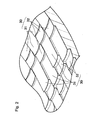
- the prisms 30 comprise a pair of the first prisms 31 and the second prisms 32 that are disposed in a regular pattern on the inner surface of the cover lens 3 as shown in Fig. 2.
- the first prisms 31 and the second prisms 32 are arranged alternately in the vertical direction and in the horizontal direction in a regular pattern.
- the direction in the lateral plane parallel to the central axis of the cover lens 3 is referred to as horizontal direction, and the direction perpendicular to the horizontal plane is referred to as vertical direction.
- the direction of line A-A' in Fig. 2 is the vertical direction.
- the prisms 30 comprise the pair of. first prisms 31 and the second prisms 32 that are disposed adjacent to each other in the vertical direction.
- each of the first prisms 31 has an incident surface consisting of a part of cylindrical surface.
- the inclination of the incident plane of each of the first prisms 31 is set such that light that is emitted by a light source located on the central axis of the cover lens 3 (light source located at a position where the LED assembly 1 is disposed) and is incident on the first prisms 31 at the center C31 thereof emerges, after passing through the first prisms 31, in a direction parallel to the central axis of the cover lens 3 (schematically shown in Fig. 3 with reference numeral 101).
- Radius and length of circumference of the cylindrical surface that constitutes the incident surface of the first prisms 31 are set such that light that is incident on the first prisms 31 and has passed therethrough spreads to a predetermined extent in the horizontal plane, while longitudinal length of the cylindrical surface that constitutes the incident surface in the direction perpendicular to the circumferential surface of the cylinder that constitutes the incident surface is set such that light that is incident on the first prisms 31 and has passed therethrough spreads to a predetermined extent in the vertical plane (plane perpendicular to the horizontal plane).
- the cylindrical surfaces that constitute the incident surfaces of the first prisms 31 are formed to be substantially equal to each other.
- the extents to which light incident on the incident surfaces of the first prisms 31 in the horizontal direction and in the vertical direction are set in accordance to the luminous intensity distribution pattern required of the LED lamp in order to form the luminous intensity distribution pattern required of the LED lamp.
- the luminous intensity distribution patterns of the first prisms 31 can be made equal to each other by forming the cylindrical surfaces that constitute the incident surfaces of the first prisms 31 substantially equal to each other and setting the inclination of the incident surface of each of the first prisms 31 such that light that is emitted by a light source located on the central axis of the cover lens 3 is incident on the first prisms 31 at the center C31 thereof and emerges therefrom in a direction parallel to the central axis of the cover lens 3
- direction and shape of the incident surfaces of the first prisms are set so that the luminous intensity distribution patterns of light emerging from the first prisms 31 are equal to each other in this embodiment.
- Fig. 4 shows the light emerging through the first prisms 31a, 31b of the two prisms 30a, 30b that are arbitrarily selected from among the plurality of prisms 30.
- the luminous intensity distribution patterns formed by the first prism 31a and the luminous intensity distribution patterns formed by the first prism 31b are formed so as to have' the same extent in the horizontal direction and in the vertical direction around the central axis of the cover lens 3 located at the center thereof, while the luminous intensity distribution patterns formed by the first prism 31a and the luminous intensity distribution patterns formed by the first prism 31b are substantially equal to each other in terms of the direction and the pattern.
- Fig. 4 shows' as if the patterns 'agree'only on an imaginary screen S100 because the screen S100 that should be at a sufficiently large distance is drawn near the cover lens 3 due to the restriction of drawing, actually diameter of the cover lens 3 is sufficiently smaller than the proportion shown in the drawing and the luminous intensity distribution patterns substantially agree with each other.
- light emitted from one light source makes one luminous intensity distribution pattern (first luminous intensity distribution pattern) through superposition of a plurality of substantially identical luminous intensity distribution patterns that are formed by different beams emerging from the plurality of first prisms 31.
- first luminous intensity distribution pattern formed by light that is output from one light source will be referred to as first light intensity distribution pattern of single light source, in order to distinguish it from a luminous intensity distribution pattern formed by light beams that are output from a plurality of light sources (light emitting diodes) to be described later.
- each of the second prisms 32 has an incident surface consisting of a part of a cylindrical surface.
- the inclination of the incident surface of each of the second prisms 32 is set such that light that is emitted by a light source located on the central axis of the cover lens 3 and is incident on the second prisms 32 at the center C32 thereof emerges, after passing through the second prisms 32, in a direction parallel to each other and below the central axis of the cover lens 3 (schematically shown in Fig. 3 with reference numeral 102).
- Radius and length of circumference of the cylindrical surface that constitutes the incident surface of the second prisms 32 are set such that light that is incident on the second prisms 32 and has passed therethrough spreads to a predetermined extent in the horizontal plane, while vertical length of the cylindrical surface that constitutes the incident surface is set such that light that is incident on the second prisms 32 and has passed therethrough spreads to a predetermined extent in the vertical plane (plane perpendicular to the horizontal plane).
- the cylindrical surfaces that constitute the incident surfaces of the second prisms 32 are formed to be substantially equal to each other.
- the extents to which light incident on the incident. surfaces of the second prisms 32 in the horizontal direction and in the vertical direction are set in accordance to the luminous intensity distribution pattern required of the LED lamp in order to form the luminous-intensity distribution pattern required of the LED lamp.
- the luminous intensity distribution patterns of light emerging from the second prisms 32 can be made equal to each other by forming the cylindrical surfaces that constitute the incident surfaces of the second prisms.32 substantially equal to each other and setting the inclination of the incident surface of the second prisms 32 such that light that is incident on the first prisms 31 at the central axis C31 thereof emerges, after passing through the first prisms 31, in directions parallel to each other
- direction and shape of the incident surfaces of the first prisms are set so that the luminous intensity distribution patterns of the second prisms 32 are equal to each other.
- Fig. 5 shows the light emerging through the second prisms 32a, 32b of the two prisms 30a, 30b that are arbitrarily selected from among the plurality of prisms 30.
- the luminous intensity distribution patterns formed by the second prism 32a and the luminous intensity distribution patterns of the second prism 32b are formed so as to have the same extent in the horizontal direction and in the vertical direction, while the luminous intensity distribution patterns formed by the second prism 32a and the luminous intensity distribution patterns. formed by the second prism 32b are substantially equal to each other in terms of the direction and the pattern.
- FIG. 5 shows as if the patterns agree only on the specific screen S100, this is due to the restriction of drawing.
- light emitted from one light source makes one luminous intensity distribution pattern (second luminous intensity distribution pattern), that is different from the first luminous intensity distribution pattern, through superposition of a plurality of substantially identical luminous intensity distribution patterns that are formed by different beams emerging from the plurality of second prisms 32.
- the second luminous intensity distribution pattern formed by light that is output from one light source will be referred to as second light intensity distribution pattern of single light source in order to distinguish it from a luminous intensity distribution pattern formed by light beams that are output from a plurality of light sources (light emitting diodes) to be described later.
- light emitted from one light source makes a luminous intensity distribution pattern (synthesized light intensity distribution pattern of single light source) through superposition of the first light intensity distribution pattern of single light source and the second light intensity distribution pattern of single light source, by being output through the cover lens 3.
- the LED assembly 1 is formed by disposing the plurality of' light emitting diodes 11 on the substrate 12 in a predetermined arrangement.
- the arrangement pattern of the light emitting diodes 11 and the intensity of light emitted by the LED are part of important elements that determine the luminous intensity distribution pattern (characteristics) of the LED lamp along with the shape of the prism 30 and arrangement of the prisms 30.
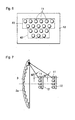
- number of the light emitting diodes 11 disposed in the upper row is made larger than the number of the light emitting diodes 11 disposed in the lower row, so that the intensity of light is different between the upper and the lower portions in the light source of the plurality of light emitting diodes, as shown in Fig. 6. Since this enables it to increase the intensity of light directed in the lower direction from the LED lamp, it is made possible to easily make the LED lamp for traffic signal that is required to direct light of higher intensity in the lower direction by combining this with the configuration of the prisms 30 of the cover lens 30 described previously.
- intensity of light emitted by the light emitting diode 11 located below the optical axis of the LED assembly 1 it is preferable to set the intensity of light emitted by the light emitting diode 11 located below the optical axis of the LED assembly 1 to 40% or less of the intensity of light emitted by the light emitting diode 11 located above the optical axis.
- intensity of light may be made different between the upper and lower portions either by the setting the number of light emitting diodes as described above, or by changing the current drawn in the light emitting diodes or the luminance level of the light emitting diodes.
- the luminous intensity distribution pattern of the LED lamp as a whole will be described below in a case where the LED lamp is constituted from a combination of the LED assembly 1 comprising the light emitting diodes disposed in the arrangement pattern described previously and the cover lens 3 of the constitution described previously.
- the luminous intensity distribution patterns of the first prisms 31a, 31b shift downward while maintaining the identical patterns when the light source is shifted to above the optical axis of the cover lens 3.
- the luminous intensity distribution patterns formed by the first prisms 31 shift to the left of the optical axis while maintaining the identical patterns when the light source is shifted to the right of the optical axis of the cover lens 3.
- the luminous intensity distribution patterns formed by the first prisms 31 shift to the right of the optical axis while maintaining the identical patterns when the light source is shifted to the left of the optical axis of the cover lens 3.
- the first prisms 32 have identical first light intensity distribution patterns of single light source while the first light intensity distribution pattern of single light source has a direction that corresponds to the position of the light source relative to the optical axis of the cover lens 3.
- the luminous intensity distribution pattern formed by the LED assembly 1 and the first prisms 32 is the superposition of all the first light -intensity distribution patterns of single light sources formed by the individual light emitting diodes 11 and the first prisms 32.
- the first light intensity distribution pattern of single light source formed by the individual light emitting diode 11 has a direction that corresponds to the position of the light emitting diode 11, the first light intensity distribution pattern of collective light source formed as the superposition of the first light intensity distribution patterns of single light sources becomes a luminous intensity distribution pattern that corresponds to the arrangement pattern of the LED assembly 1.
- the first light intensity distribution pattern of collective light source has a light intensity distribution that is stronger in the lower portion.
- the luminous intensity distribution patterns formed by the second prisms 32a, 32b shift downward while maintaining the identical patterns when the light source is shifted to above the optical axis of the cover lens 3.
- the luminous intensity distribution patterns formed by the second prisms 32 shift to the left of the optical axis while maintaining the identical patterns when the light source is shifted to the right of the optical axis of the cover lens 3, while the luminous intensity distribution patterns formed by the second prisms 32 shift to the right of the optical axis while maintaining the identical patterns when the light source is shifted to the left of the optical axis of the cover lens 3.
- the second prisms 32 similarly to the case of the first prisms 31, even when the light source is located at a position offset from the optical axis of the cover lens 3, the second prisms 32 have identical second light intensity distribution patterns of single light sources, while the second light intensity distribution pattern of single light source has a direction that corresponds to the position of the light source relative to the optical axis of the cover lens 3.
- the second light intensity distribution pattern of collective light source formed by the LED assembly 1 and the first prisms 32 is the superposition of all the second light intensity distribution patterns of single light sources and becomes a luminous intensity distribution pattern that corresponds to'the arrangement pattern of the LED assembly 1.
- the second light intensity distribution pattern of collective light source has a light intensity distribution that is stronger in the lower portion.
- the luminous intensity distribution pattern of the LED lamp formed by combining the LED assembly 1 and the cover lens 3 in this embodiment is the luminous intensity distribution pattern formed by synthesizing the first light intensity distribution pattern of collective light source formed by the arrangement pattern of the LED assembly 1 and the first prisms 31 and the second light intensity distribution pattern of collective light source formed by the arrangement pattern of the LED assembly 1 and the second prisms 32.
- the luminous intensity distribution pattern of the LED lamp of this embodiment is achieved by combining (1) the arrangement pattern of the plurality of light emitting diodes 11, (2) assembly of the plurality of first prisms 31 and (3) assembly of the plurality of second prisms 32.
- the distance between the cover lens 3 and the LED assembly 1 is not restricted by the fact that the particular cover lens 3 and the LED assembly 1 are used.
- the distance is preferably set within a range described below in consideration of the directivity characteristic of the light emitting diode and the required size of the LED lamp.
- the distance between the cover lens 3 and the LED assembly 1 such- that the angle between the line, that connects the light emitting diode 11 located at the outermost position of the LED assembly 1 and the periphery of the cover lens 3 on the inner surface thereof, and the central axis of the cover lens 3 is not larger than 60°C.
- this angle being larger than 60°C leads to insufficient intensity of light incident on a part located away from the center of the cover lens 3 due to the directivity characteristic of the light emitting diode, thus making it impossible to achieve uniform planar light emission (as the periphery of the cover lens darkens), resulting in lower efficiency of light emission.
- the distance between the cover lens 3 and the LED assembly 1 such that the angle between the line, that connects the light emitting diode 11 located at the outermost position of the LED assembly 1 and the periphery of the cover lens 3 on the inner surface thereof, and the central axis of the cover lens 3 is 30°C or larger.
- this angle being smaller than 30°C increases the light collecting power but leads to greater burden of diffusing light imposed on the cover lens, thus resulting in lower efficiency of light emission and larger profile of the LED lamp.
- the outer surface of the cover lens is preferably formed in a spherical surface having a radius of curvature not larger than 500 mm. Forming the outer surface with this curvature also allows it to suppress the height of cut in the prisms and improve the efficiency of light emission.
- the LED lamp of this embodiment described above is constituted from a combination of the LED assembly 1 comprising the plurality of light emitting diodes disposed in the predetermined arrangement pattern and the cover lens 3 having the plurality of prisms 30, desired luminous intensity distribution pattern can be achieved with a simple construction.
- the predetermined luminous intensity distribution pattern is formed by using the cover lens 3 having prisms 30 that comprise the pair of first prisms 31 and the second prisms 32 formed on the inner surface thereof in a regular pattern and the LED assembly 1 comprising the plurality of light emitting diodes disposed in the predetermined arrangement in the preferred embodiment described above, the present invention is not limited to this constitution and may be implemented with various modifications as follows.
- the present invention may also be embodied by using only the plurality of first prisms 31 constituted similarly to the above embodiment, thereby forming the predetermined luminous intensity distribution pattern.
- a relatively simple luminous intensity distribution pattern that is required to concentrate light with high intensity around the optical axis of the cover lens can be achieved only by means of the plurality of first prisms 31 as shown in Fig. 4.
- the arrangement of the light emitting diodes in the LED assembly may be a simple one such as concentric circles.
- the present invention may also be embodied by using only the plurality of second prisms 31 constituted similarly to the above embodiment, thereby forming the predetermined luminous intensity distribution pattern.
- a relatively simple luminous intensity distribution pattern that is required to concentrate light with high intensity in the lower portion can be achieved only by means of the plurality of second prisms 31 as shown in Fig. 5.
- the arrangement of the light emitting diodes in the LED assembly may be a simple one such as concentric circles.
- the present invention may also be. embodied by using only the first prisms 31 and the second prisms 32 constituted similarly to the above embodiment, thereby forming the predetermined luminous intensity distribution pattern.
- the arrangement of the light emitting diodes in the LED assembly may be a simple one such as concentric circles.
- an LED lamp that is capable of achieving a desired luminous intensity distribution characteristic and producing uniform planar light emission, and therefore traffic signals, information display apparatuses or the like that is capable of achieving a desired luminous intensity distribution characteristic and producing uniform planar light emission can be made by using this LED lamp.
Landscapes
- Engineering & Computer Science (AREA)
- Manufacturing & Machinery (AREA)
- General Engineering & Computer Science (AREA)
- Physics & Mathematics (AREA)
- General Physics & Mathematics (AREA)
- Led Device Packages (AREA)
- Non-Portable Lighting Devices Or Systems Thereof (AREA)
- Illuminated Signs And Luminous Advertising (AREA)
- Traffic Control Systems (AREA)
- Arrangement Of Elements, Cooling, Sealing, Or The Like Of Lighting Devices (AREA)
Abstract
Description
Claims (10)
- A LED lamp comprising a plurality of light emitting diodes and a cover lens so that a light emitted by the plurality of light emitting diodes is output through the cover lens,
wherein an inner surface of said cover lens is provided with a plurality of prisms including a plurality of first prisms, directions and shapes of the first prisms are set so that said first prisms output light in first luminous intensity distribution patterns that are substantially equal to each other. - The LED lamp according to claim 1;
wherein a direction of the light that is output through said first prisms in the vertical plane is set by a direction of said incident surface, and a diffusion of the light that is output through said first prisms in the horizontal plane is set by the configuration of said incident plane. - The LED lamp as in one of claims 1-2;
wherein said plurality of prisms include a plurality of second prisms and the directions and shapes of the incident surfaces of said second prisms are set so that the second prisms have second luminous intensity distribution patterns that are substantially equal to each other. - The LED lamp according to claim 3;
wherein a direction of the light that is output through said second prisms in the vertical plane is set by a direction of said incident surface, and a diffusion of the light that is output through said second prisms in the horizontal plane is set by the configuration of said incident plane. - The LED lamp as in one of claims 3-4;
wherein said first prisms and said second prisms form pairs which are consist of one of said first prisms and one of said second prisms, said pairs are arranged on the inner surface of said cover lens according to a rule. - The LED lamp as in one of claims 3-5;
wherein said second prisms are formed so as to direct the light below the light output from said first prisms. - The LED lamp as in one of claims 3-6;
wherein said plurality of light emitting diodes are disposed in an arrangement pattern determined according to the luminous intensity distribution pattern required in the LED lamp. - The LED lamp according to claim 7;
wherein said arrangement pattern is set so that the number of light emitting diodes located below the horizontal plane that includes the central axis of the cover lens is set to 40% or less of the total number of the light emitting diodes. - The LED lamp according to claim 8;
wherein the angle between the line, that connects the light emitting diode located at the outermost position of the arrangement pattern and the periphery of the cover lens on the inner surface thereof, and the central axis of the cover lens is in range from 30° to 60° . - The LED lamp as in one of claims 1-9;
wherein said cover lens has the external surface that is a spherical surface of which radius of curvature is 500 mm or less.
Applications Claiming Priority (3)
| Application Number | Priority Date | Filing Date | Title |
|---|---|---|---|
| JP2001195079 | 2001-06-27 | ||
| JP2001195079A JP2003016804A (en) | 2001-06-27 | 2001-06-27 | LED indicator light |
| PCT/JP2002/006464 WO2003002907A1 (en) | 2001-06-27 | 2002-06-27 | Led indicator light |
Publications (3)
| Publication Number | Publication Date |
|---|---|
| EP1406042A1 true EP1406042A1 (en) | 2004-04-07 |
| EP1406042A4 EP1406042A4 (en) | 2005-07-20 |
| EP1406042B1 EP1406042B1 (en) | 2007-03-28 |
Family
ID=19033115
Family Applications (1)
| Application Number | Title | Priority Date | Filing Date |
|---|---|---|---|
| EP02736180A Expired - Lifetime EP1406042B1 (en) | 2001-06-27 | 2002-06-27 | Led indicator light |
Country Status (5)
| Country | Link |
|---|---|
| US (1) | US6808293B2 (en) |
| EP (1) | EP1406042B1 (en) |
| JP (1) | JP2003016804A (en) |
| DE (1) | DE60219171T2 (en) |
| WO (1) | WO2003002907A1 (en) |
Cited By (1)
| Publication number | Priority date | Publication date | Assignee | Title |
|---|---|---|---|---|
| US7993022B2 (en) | 2007-08-31 | 2011-08-09 | Osram Gesellschaft mit beschränkter Haftung | Illuminating module for a lighting device |
Families Citing this family (55)
| Publication number | Priority date | Publication date | Assignee | Title |
|---|---|---|---|---|
| US8035612B2 (en) | 2002-05-28 | 2011-10-11 | Intellectual Ventures Holding 67 Llc | Self-contained interactive video display system |
| US7710391B2 (en) | 2002-05-28 | 2010-05-04 | Matthew Bell | Processing an image utilizing a spatially varying pattern |
| AU2003301043A1 (en) * | 2002-12-13 | 2004-07-09 | Reactrix Systems | Interactive directed light/sound system |
| US7267466B2 (en) * | 2003-08-26 | 2007-09-11 | Valeo Sylvania Llc | Cargo lamp assembly for vehicles |
| CN1902930B (en) | 2003-10-24 | 2010-12-15 | 瑞克楚斯系统公司 | Method and system for managing interactive video display system |
| US20070058378A1 (en) * | 2004-03-11 | 2007-03-15 | Hideo Moriyama | Socket device |
| JP4615949B2 (en) * | 2004-09-29 | 2011-01-19 | Idec株式会社 | Indicator light |
| US9128519B1 (en) | 2005-04-15 | 2015-09-08 | Intellectual Ventures Holding 67 Llc | Method and system for state-based control of objects |
| US8081822B1 (en) | 2005-05-31 | 2011-12-20 | Intellectual Ventures Holding 67 Llc | System and method for sensing a feature of an object in an interactive video display |
| CN1936415A (en) * | 2005-09-23 | 2007-03-28 | 鸿富锦精密工业(深圳)有限公司 | Light-emitting-diode array and lamp source adopting said L-E-D array |
| US8098277B1 (en) | 2005-12-02 | 2012-01-17 | Intellectual Ventures Holding 67 Llc | Systems and methods for communication between a reactive video system and a mobile communication device |
| JP4729441B2 (en) * | 2006-06-09 | 2011-07-20 | スタンレー電気株式会社 | Vehicle lighting |
| US20080019129A1 (en) * | 2006-07-24 | 2008-01-24 | Chin-Wen Wang | LED Lamp Illumination Projecting Structure |
| US20080052508A1 (en) * | 2006-08-25 | 2008-02-28 | Huotari Allen J | Network security status indicators |
| US7618163B2 (en) * | 2007-04-02 | 2009-11-17 | Ruud Lighting, Inc. | Light-directing LED apparatus |
| WO2008124820A1 (en) * | 2007-04-10 | 2008-10-16 | Reactrix Systems, Inc. | Display using a three dimensional vision system |
| WO2009014387A2 (en) * | 2007-07-26 | 2009-01-29 | Fawoo Technology Co., Ltd. | Stick-type led lighting apparatus |
| CA2699628A1 (en) * | 2007-09-14 | 2009-03-19 | Matthew Bell | Gesture-based user interactions with status indicators for acceptable inputs in volumetric zones |
| US8159682B2 (en) | 2007-11-12 | 2012-04-17 | Intellectual Ventures Holding 67 Llc | Lens system |
| US20100039500A1 (en) * | 2008-02-15 | 2010-02-18 | Matthew Bell | Self-Contained 3D Vision System Utilizing Stereo Camera and Patterned Illuminator |
| US8259163B2 (en) | 2008-03-07 | 2012-09-04 | Intellectual Ventures Holding 67 Llc | Display with built in 3D sensing |
| US8388193B2 (en) | 2008-05-23 | 2013-03-05 | Ruud Lighting, Inc. | Lens with TIR for off-axial light distribution |
| US8348475B2 (en) | 2008-05-23 | 2013-01-08 | Ruud Lighting, Inc. | Lens with controlled backlight management |
| US9423096B2 (en) | 2008-05-23 | 2016-08-23 | Cree, Inc. | LED lighting apparatus |
| US8595218B2 (en) | 2008-06-12 | 2013-11-26 | Intellectual Ventures Holding 67 Llc | Interactive display management systems and methods |
| US7841750B2 (en) | 2008-08-01 | 2010-11-30 | Ruud Lighting, Inc. | Light-directing lensing member with improved angled light distribution |
| US9255686B2 (en) | 2009-05-29 | 2016-02-09 | Cree, Inc. | Multi-lens LED-array optic system |
| US8662704B2 (en) | 2009-08-14 | 2014-03-04 | U.S. Pole Company, Inc. | LED optical system with multiple levels of secondary optics |
| US8317365B2 (en) * | 2010-03-30 | 2012-11-27 | Lisa Tracy | Fluorescent bulb cover |
| USD634885S1 (en) * | 2010-04-10 | 2011-03-22 | Lg Innotek Co., Ltd. | LED lamp module |
| USD634883S1 (en) * | 2010-04-10 | 2011-03-22 | Lg Innotek Co., Ltd. | Lens for LED lamp |
| USD632839S1 (en) * | 2010-04-10 | 2011-02-15 | Lg Innotek Co., Ltd | LED lamp module |
| USD634882S1 (en) * | 2010-04-10 | 2011-03-22 | Lg Innotek Co., Ltd. | Lens for LED lamp |
| KR101033541B1 (en) | 2010-12-14 | 2011-05-11 | 강원대학교산학협력단 | LED dedicated prism luminaire |
| JP5656783B2 (en) * | 2011-09-13 | 2015-01-21 | 日野自動車株式会社 | Vehicle lighting |
| US9541258B2 (en) | 2012-02-29 | 2017-01-10 | Cree, Inc. | Lens for wide lateral-angle distribution |
| US10408429B2 (en) | 2012-02-29 | 2019-09-10 | Ideal Industries Lighting Llc | Lens for preferential-side distribution |
| US9541257B2 (en) | 2012-02-29 | 2017-01-10 | Cree, Inc. | Lens for primarily-elongate light distribution |
| USD697664S1 (en) | 2012-05-07 | 2014-01-14 | Cree, Inc. | LED lens |
| USD715481S1 (en) * | 2013-03-11 | 2014-10-14 | Wan-Jiong Lin | Lens |
| USD715991S1 (en) * | 2013-03-11 | 2014-10-21 | Wan-Jiong Lin | Lens |
| USD715990S1 (en) * | 2013-03-11 | 2014-10-21 | Wan-Jiong Lin | Lens |
| USD718490S1 (en) | 2013-03-15 | 2014-11-25 | Cree, Inc. | LED lens |
| USD719700S1 (en) * | 2013-10-24 | 2014-12-16 | Aether Systems Inc. | Optical lens for light emitting device |
| US9523479B2 (en) | 2014-01-03 | 2016-12-20 | Cree, Inc. | LED lens |
| USD770552S1 (en) * | 2014-05-30 | 2016-11-01 | Osram Sylvania Inc. | Flexible optic |
| WO2015187514A1 (en) | 2014-06-01 | 2015-12-10 | Osram Sylvania Inc. | Luminaire with glare control |
| USD843625S1 (en) | 2014-06-05 | 2019-03-19 | Nvent Services Gmbh | Lighted cable termination assembly |
| US9816680B2 (en) | 2014-06-05 | 2017-11-14 | Pentair Thermal Management Llc | Lighted cable termination device having expanded viewing area |
| USD1093689S1 (en) | 2014-06-05 | 2025-09-16 | Chemelex Europe Gmbh | Lighted cable termination assembly |
| USD771172S1 (en) * | 2015-08-28 | 2016-11-08 | Chun Kuang Optics Corp. | Lens |
| US10468566B2 (en) | 2017-04-10 | 2019-11-05 | Ideal Industries Lighting Llc | Hybrid lens for controlled light distribution |
| TWI770275B (en) * | 2017-11-15 | 2022-07-11 | 光林智能科技股份有限公司 | Light distribution module |
| US11125414B2 (en) * | 2017-11-15 | 2021-09-21 | Lite-On Electronics (Guangzhou) Limited | Light distribution module |
| CN113646579B (en) | 2019-03-26 | 2024-10-29 | 昕诺飞控股有限公司 | Light-emitting device |
Family Cites Families (12)
| Publication number | Priority date | Publication date | Assignee | Title |
|---|---|---|---|---|
| US4152756A (en) * | 1977-06-27 | 1979-05-01 | General Signal Corporation | Railroad crossing signal lamp |
| KR890005451A (en) * | 1987-09-21 | 1989-05-15 | 마쯔우라 다까오 | Vehicle lamp |
| JPH0446322Y2 (en) * | 1988-08-02 | 1992-10-30 | ||
| JPH06349307A (en) * | 1993-06-11 | 1994-12-22 | Nikon Corp | traffic light |
| SE503306C2 (en) * | 1994-03-16 | 1996-05-13 | Itab Ind Ab | ILLUMINATOR |
| US5632551A (en) * | 1994-07-18 | 1997-05-27 | Grote Industries, Inc. | LED vehicle lamp assembly |
| US5833355A (en) * | 1996-12-06 | 1998-11-10 | Dialight Corporation | Led illuminated lamp assembly |
| CN1105852C (en) * | 1996-10-16 | 2003-04-16 | 皇家菲利浦电子有限公司 | Signal lamp with LEDS |
| SE511216C2 (en) * | 1997-12-30 | 1999-08-23 | Itab Neon Ab | Lighting device with LEDs |
| US5896093A (en) * | 1998-04-03 | 1999-04-20 | Sjobom; Fritz C. | L.E.D. light assembly for traffic arrowboards |
| JP2000113385A (en) * | 1998-10-05 | 2000-04-21 | Kyosan Electric Mfg Co Ltd | Lamp for traffic signal |
| JP2000276693A (en) * | 1999-03-26 | 2000-10-06 | Stanley Electric Co Ltd | Traffic light |
-
2001
- 2001-06-27 JP JP2001195079A patent/JP2003016804A/en active Pending
-
2002
- 2002-06-27 US US10/362,753 patent/US6808293B2/en not_active Expired - Lifetime
- 2002-06-27 DE DE60219171T patent/DE60219171T2/en not_active Expired - Lifetime
- 2002-06-27 EP EP02736180A patent/EP1406042B1/en not_active Expired - Lifetime
- 2002-06-27 WO PCT/JP2002/006464 patent/WO2003002907A1/en not_active Ceased
Cited By (1)
| Publication number | Priority date | Publication date | Assignee | Title |
|---|---|---|---|---|
| US7993022B2 (en) | 2007-08-31 | 2011-08-09 | Osram Gesellschaft mit beschränkter Haftung | Illuminating module for a lighting device |
Also Published As
| Publication number | Publication date |
|---|---|
| JP2003016804A (en) | 2003-01-17 |
| EP1406042A4 (en) | 2005-07-20 |
| US20040095768A1 (en) | 2004-05-20 |
| WO2003002907A1 (en) | 2003-01-09 |
| US6808293B2 (en) | 2004-10-26 |
| DE60219171T2 (en) | 2008-01-03 |
| EP1406042B1 (en) | 2007-03-28 |
| DE60219171D1 (en) | 2007-05-10 |
Similar Documents
| Publication | Publication Date | Title |
|---|---|---|
| EP1406042B1 (en) | Led indicator light | |
| US6929384B2 (en) | Led indicator lamp | |
| KR100486334B1 (en) | Vehicle lighting device using led light source | |
| US4698734A (en) | Lensed indirect luminaire with side angle brightness control | |
| EP1681509B1 (en) | Luminescent light source and luminescent source array | |
| US7995882B2 (en) | Lighting device comprising a plurality of semiconductor light sources | |
| JP2567552B2 (en) | Light emitting diode lamp with refractive lens element | |
| US5769532A (en) | Signal warning and displaying lamp | |
| US8717679B2 (en) | Lens for LED lamps | |
| US20030174501A1 (en) | LED symbol signal | |
| CA2380538A1 (en) | Led traffic light with individual led reflectors | |
| WO2022071161A1 (en) | Light source device and light guide array unit | |
| JP4631375B2 (en) | Signal light | |
| US4538216A (en) | Lighting apparatus | |
| JP2008507639A (en) | Road marking device and system | |
| US20160363711A1 (en) | Lighting system with improved illumination distribution and output luminance variation | |
| EP1064637A1 (en) | Lighting means having light emitting diodes | |
| JPS63155782A (en) | Light source device | |
| US20020149494A1 (en) | LED symbol signal | |
| US10008137B2 (en) | Illuminated sign with compartmented portion | |
| JP3493630B2 (en) | LED traffic light fixture | |
| KR100938870B1 (en) | Diffussion lense for led module radiating white light | |
| JP2000164010A (en) | Vehicle lamp with LED as light source | |
| JP2002015603A (en) | LED display | |
| JPH04108806U (en) | Signal notification indicator light |
Legal Events
| Date | Code | Title | Description |
|---|---|---|---|
| PUAI | Public reference made under article 153(3) epc to a published international application that has entered the european phase |
Free format text: ORIGINAL CODE: 0009012 |
|
| 17P | Request for examination filed |
Effective date: 20040127 |
|
| AK | Designated contracting states |
Kind code of ref document: A1 Designated state(s): AT BE CH CY DE DK ES FI FR GB GR IE IT LI LU MC NL PT SE TR |
|
| A4 | Supplementary search report drawn up and despatched |
Effective date: 20050602 |
|
| RIC1 | Information provided on ipc code assigned before grant |
Ipc: 7F 21S 8/00 B Ipc: 7G 08G 1/095 B Ipc: 7F 21S 2/00 A |
|
| GRAP | Despatch of communication of intention to grant a patent |
Free format text: ORIGINAL CODE: EPIDOSNIGR1 |
|
| GRAS | Grant fee paid |
Free format text: ORIGINAL CODE: EPIDOSNIGR3 |
|
| GRAA | (expected) grant |
Free format text: ORIGINAL CODE: 0009210 |
|
| AK | Designated contracting states |
Kind code of ref document: B1 Designated state(s): DE FR GB |
|
| REG | Reference to a national code |
Ref country code: GB Ref legal event code: FG4D |
|
| REF | Corresponds to: |
Ref document number: 60219171 Country of ref document: DE Date of ref document: 20070510 Kind code of ref document: P |
|
| ET | Fr: translation filed | ||
| PLBE | No opposition filed within time limit |
Free format text: ORIGINAL CODE: 0009261 |
|
| STAA | Information on the status of an ep patent application or granted ep patent |
Free format text: STATUS: NO OPPOSITION FILED WITHIN TIME LIMIT |
|
| 26N | No opposition filed |
Effective date: 20080102 |
|
| PGFP | Annual fee paid to national office [announced via postgrant information from national office to epo] |
Ref country code: DE Payment date: 20120620 Year of fee payment: 11 |
|
| PGFP | Annual fee paid to national office [announced via postgrant information from national office to epo] |
Ref country code: FR Payment date: 20120619 Year of fee payment: 11 Ref country code: GB Payment date: 20120627 Year of fee payment: 11 |
|
| GBPC | Gb: european patent ceased through non-payment of renewal fee |
Effective date: 20130627 |
|
| REG | Reference to a national code |
Ref country code: FR Ref legal event code: ST Effective date: 20140228 |
|
| REG | Reference to a national code |
Ref country code: DE Ref legal event code: R119 Ref document number: 60219171 Country of ref document: DE Effective date: 20140101 |
|
| PG25 | Lapsed in a contracting state [announced via postgrant information from national office to epo] |
Ref country code: GB Free format text: LAPSE BECAUSE OF NON-PAYMENT OF DUE FEES Effective date: 20130627 Ref country code: DE Free format text: LAPSE BECAUSE OF NON-PAYMENT OF DUE FEES Effective date: 20140101 |
|
| PG25 | Lapsed in a contracting state [announced via postgrant information from national office to epo] |
Ref country code: FR Free format text: LAPSE BECAUSE OF NON-PAYMENT OF DUE FEES Effective date: 20130701 |