EP1406032B1 - Hydraulic control apparatus for V-belt type continuously variable transmission - Google Patents
Hydraulic control apparatus for V-belt type continuously variable transmission Download PDFInfo
- Publication number
- EP1406032B1 EP1406032B1 EP03255490A EP03255490A EP1406032B1 EP 1406032 B1 EP1406032 B1 EP 1406032B1 EP 03255490 A EP03255490 A EP 03255490A EP 03255490 A EP03255490 A EP 03255490A EP 1406032 B1 EP1406032 B1 EP 1406032B1
- Authority
- EP
- European Patent Office
- Prior art keywords
- pressure
- line pressure
- oil
- hydraulic control
- range
- Prior art date
- Legal status (The legal status is an assumption and is not a legal conclusion. Google has not performed a legal analysis and makes no representation as to the accuracy of the status listed.)
- Expired - Fee Related
Links
Images


Classifications
-
- F—MECHANICAL ENGINEERING; LIGHTING; HEATING; WEAPONS; BLASTING
- F16—ENGINEERING ELEMENTS AND UNITS; GENERAL MEASURES FOR PRODUCING AND MAINTAINING EFFECTIVE FUNCTIONING OF MACHINES OR INSTALLATIONS; THERMAL INSULATION IN GENERAL
- F16H—GEARING
- F16H61/00—Control functions within control units of change-speed- or reversing-gearings for conveying rotary motion ; Control of exclusively fluid gearing, friction gearing, gearings with endless flexible members or other particular types of gearing
- F16H61/66—Control functions within control units of change-speed- or reversing-gearings for conveying rotary motion ; Control of exclusively fluid gearing, friction gearing, gearings with endless flexible members or other particular types of gearing specially adapted for continuously variable gearings
- F16H61/662—Control functions within control units of change-speed- or reversing-gearings for conveying rotary motion ; Control of exclusively fluid gearing, friction gearing, gearings with endless flexible members or other particular types of gearing specially adapted for continuously variable gearings with endless flexible members
- F16H61/66272—Control functions within control units of change-speed- or reversing-gearings for conveying rotary motion ; Control of exclusively fluid gearing, friction gearing, gearings with endless flexible members or other particular types of gearing specially adapted for continuously variable gearings with endless flexible members characterised by means for controlling the torque transmitting capability of the gearing
-
- F—MECHANICAL ENGINEERING; LIGHTING; HEATING; WEAPONS; BLASTING
- F16—ENGINEERING ELEMENTS AND UNITS; GENERAL MEASURES FOR PRODUCING AND MAINTAINING EFFECTIVE FUNCTIONING OF MACHINES OR INSTALLATIONS; THERMAL INSULATION IN GENERAL
- F16H—GEARING
- F16H61/00—Control functions within control units of change-speed- or reversing-gearings for conveying rotary motion ; Control of exclusively fluid gearing, friction gearing, gearings with endless flexible members or other particular types of gearing
- F16H61/0021—Generation or control of line pressure
-
- F—MECHANICAL ENGINEERING; LIGHTING; HEATING; WEAPONS; BLASTING
- F16—ENGINEERING ELEMENTS AND UNITS; GENERAL MEASURES FOR PRODUCING AND MAINTAINING EFFECTIVE FUNCTIONING OF MACHINES OR INSTALLATIONS; THERMAL INSULATION IN GENERAL
- F16H—GEARING
- F16H61/00—Control functions within control units of change-speed- or reversing-gearings for conveying rotary motion ; Control of exclusively fluid gearing, friction gearing, gearings with endless flexible members or other particular types of gearing
- F16H61/04—Smoothing ratio shift
- F16H61/06—Smoothing ratio shift by controlling rate of change of fluid pressure
-
- F—MECHANICAL ENGINEERING; LIGHTING; HEATING; WEAPONS; BLASTING
- F16—ENGINEERING ELEMENTS AND UNITS; GENERAL MEASURES FOR PRODUCING AND MAINTAINING EFFECTIVE FUNCTIONING OF MACHINES OR INSTALLATIONS; THERMAL INSULATION IN GENERAL
- F16H—GEARING
- F16H61/00—Control functions within control units of change-speed- or reversing-gearings for conveying rotary motion ; Control of exclusively fluid gearing, friction gearing, gearings with endless flexible members or other particular types of gearing
- F16H61/66—Control functions within control units of change-speed- or reversing-gearings for conveying rotary motion ; Control of exclusively fluid gearing, friction gearing, gearings with endless flexible members or other particular types of gearing specially adapted for continuously variable gearings
-
- F—MECHANICAL ENGINEERING; LIGHTING; HEATING; WEAPONS; BLASTING
- F16—ENGINEERING ELEMENTS AND UNITS; GENERAL MEASURES FOR PRODUCING AND MAINTAINING EFFECTIVE FUNCTIONING OF MACHINES OR INSTALLATIONS; THERMAL INSULATION IN GENERAL
- F16H—GEARING
- F16H59/00—Control inputs to control units of change-speed-, or reversing-gearings for conveying rotary motion
- F16H59/68—Inputs being a function of gearing status
- F16H2059/6823—Sensing neutral state of the transmission
Definitions
- the present invention relates to a hydraulic control apparatus for a V-belt type continuously variable transmission, which is capable of controlling a line pressure and a secondary pressure in accordance with the oil amount balance of an oil pump.
- V-belt CVT V-belt type continuously variable transmission
- the belt CVT is constructed by winding the V-belt around a primary pulley and a secondary pulley, and groove widths of the primary pulley and the secondary pulley are variably controlled by oil pressure.
- An oil pump is connected to an input shaft of the belt CVT, and a pressure regulating valve regulates an oil pressure generated by the oil pump to generate a line pressure.
- a first cylinder chamber and a second cylinder chamber are provided to the primary pulley and the secondary pulley, respectively.
- the line pressure is supplied to the first cylinder chamber via a shift control valve as a primary pressure, and a secondary pressure obtained by regulating the line pressure is supplied to the second cylinder chamber.
- the groove widths of the primary pulley and the secondary pulley are changed according to the oil pressures supplied to the respective cylinder chambers, and the gear ratio continuously varies according to the radius of contact between the V belt and each of the pulleys.
- the primary pressure receiving area of the first cylinder chamber and the secondary pressure receiving area of the second cylinder chamber are set to be equal (see for example, Japanese Laid-Open Patent Publication No. 2001-165293 ).
- the conventional belt CVT as described above has the problem that in the case when the shift range is switched from a D range to an N range and then switched to the D range while an accelerator pedal is kept OFF in a high vehicle speed range, the oil pump which generates basic pressure for the line pressure cannot generate a specified oil pressure due to a decrease in the engine speed in the N range. Therefore, the actual line pressure, primary pressure, and secondary pressure and equal to each other, and hence a high vehicle speed gear ratio cannot be maintained and a downshift occurs.
- EP 0 440 422 shows the features of the preamble of claim 1 and discloses a hydraulic control apparatus for a vehicle continuously variable transmission including a pressure regulating valve having a valve spool which operates depending upon a determined current speed ratio of the transmission and a currently detected required output of the vehicle engine, to generate a controlled belt tensioning pressure for controlling the tension of a transmission belt at a required minimum level.
- US 5, 569, 114 discloses a pulley thrust pressure control apparatus for a belt-type continuously variable transmission having a drive pulley connected with an input member, a driven pulley connected with an output member, a V-belt trained around the drive and driven pulleys, a drive cylinder for varying the pulley width of the drive pulley, and a driven cylinder for varying the pulley width of the driven pulley.
- EP 1 394 446 is an interfering document which describes a vehicle engine connected with a belt-type continuously variable transmission via a clutch.
- the transmission transmits torque via a belt between a pair of pulleys, and varies the transmission torque according to a supply of oil pressure.
- the clutch engages by means of oil pressure supplied as a shift lever is changed over from a neutral range to a drive range.
- US 5, 067, 603 describes an apparatus for controlling a hydraulic clutch, including a two-position clutch control valve, a two-position rapid clutch release valve, and a first fluid passage system for releasing the clutch, a second fluid passage system for engaging the clutch, and a third fluid passage system for releasing the clutch. These three passage systems are selected by respective three combinations of the operating positions of the two valves.
- V-belt type continuously variable transmission which is capable of preventing a specified line pressure from becoming higher than an oil pressure generated by an oil pump.
- a hydraulic control apparatus for a V-belt type continuously variable transmission in which a primary pressure is applied on the primary pulley connected to an engine side and a secondary pressure is applied on the secondary pulley connected to an output shaft, comprising: an oil pump connected to the engine, for generating a basic pressure for a line pressure which is a basic pressure for the primary pressure and the secondary pressure; a hydraulic control section that controls the line pressure and the secondary pressure; range detecting means for detecting a range selected by an operator; and engine speed detecting means for detecting a revolution speed of the engine; and wherein the hydraulic control section is operable during a predetermined period of time after the range detecting means detects a change from a driving range to a non-driving range or a change from the non-driving range to the driving range, or when the non-driving range is detected, for calculating a value of the line pressure according to oil amount balance of the oil pump relative to the engine speed and controlling the line pressure according to the calculated value of
- the hydraulic control section controls the line pressure according to the oil amount balance of the oil pump relative to the engine speed. Therefore, it is possible to prevent a specified line pressure from becoming higher than the oil pressure generated by the oil pump even in the case where the oil pressure generated by the oil pump is reduced due to a decrease in the engine speed.
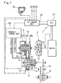
- FIG. 1 is a diagram schematically showing a belt CVT according to an embodiment of the present invention
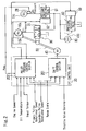
- FIG. 2 is a diagram schematically showing the constructions of a hydraulic control unit and a CVT control unit.
- a belt CVT 3 comprised of a transmission mechanism 5 including a forward-backward driving switching mechanism, not shown, and a torque converter 2 including a lock-up clutch is connected to an engine 1.
- the transmission mechanism 5 is comprised of a pair of variable pulleys consisting of a primary pulley 10 connected to an input shaft side and a secondary pulley 13 connected to an output shaft 13, and the pair of variable pulleys 10 and 11 are connected to each other via a V belt 12. It should be noted that the output shaft 13 is connected to a differential gear 6 via an idler gear 14.
- the gear ratio of the transmission 5 and the contact frictional force of the V belt 12 are controlled by a hydraulic control unit 100 that is operable in response to commands given from a CVT control unit 20.
- the CVT control unit 20 is connected to an engine control unit (hereinafter referred to as "ECU") 21 that controls the engine 1 so that the CVT control unit 20 and the ECU 21 can exchange information with each other.
- the CVT control unit 20 determines the gear ratio and the contact frictional force according to input torque information obtained from the ECU 21, the throttle valve opening (TVO) obtained from a throttle opening sensor 24, and so forth. Further, an engine speed sensor 15 that detects the revolution speed of the engine 1 is connected to the ECU 21.
- the primary pulley 10 of the transmission mechanism 5 is comprised of a fixed conical plate 10b that rotates integrally with an input shaft, and a movable conical plate 10a that is opposed to the fixed conical plate 10b to form a V-shaped pulley groove and is capable of being displaced in the axial direction according to oil pressure (hereinafter referred to as "primary pressure") applied to a primary pulley cylinder chamber 10c.
- primary pressure oil pressure
- the secondary pulley 11 is comprised of a fixed conical plate 11b that rotates integrally with the output shaft 13, and a movable conical plate 11a that is opposed to the fixed conical plate 11b to form a V-shaped pulley groove and is capable of being displaced in the axial direction according to oil pressure (hereinafter referred to as "secondary pressure") applied to a secondary pulley cylinder chamber 11c.
- secondary pressure oil pressure
- the pressure-receiving area of the primary pulley cylinder chamber 10c is set to be equal to that of the secondary pulley cylinder chamber 11c.
- the torque inputted from the engine 1 is inputted to the transmission mechanism 5 via the torque converter 2, and is transmitted from the primary pulley 10 to the secondary pulley 11 via the V belt 12.
- the movable conical plate 10a of the primary pulley 10 and the movable conical plate 11a of the secondary pulley 11 are displaced in the axial direction to change the radius of contact between the V belt 12 and each of the pulleys 10 and 11, so that the gear ratio between the primary pulley 10 and the secondary pulley 11 can be changed continuously.
- the hydraulic control unit 100 is comprised mainly of a pressure regulating valve 60 that controls the line pressure, a shift control valve 30 that controls the primary (Pri) pressure which is applied to the primary pulley cylinder chamber 10c, and a pressure reducing valve 61 that controls the secondary (Sec) pressure which is applied to the secondary pulley cylinder chamber 11c.
- the shift control valve 30 is connected to a servo link 50 constituting a mechanical feedback mechanism, so that the shift control valve 30 is driven by a step motor 40 connected to one end of the servo link 50 and receives feedback of the groove width, i.e. the actual gear ratio from the movable conical plate 10a of the primary pulley 10 connected to the other end of the servo link 50.
- a line pressure control system is comprised of the pressure regulating valve 60 including a solenoid 59 that regulates pressure oil supplied from an oil pump 80, so that the pressure oil is controlled to a predetermined line pressure according to the driving condition in accordance with a command (e.g. a duty signal) given from the CVT control unit 20.
- the line pressure is supplied to the shift control vale 30 that controls the primary pressure, and the pressure reducing valve 61 provided with a solenoid 62 that controls the secondary pressure.
- the oil pump 80 is connected to the input shaft of the belt CVT 3 and is driven by engine revolution to generate oil pressure.
- the gear ratio of the primary pulley 10 to the secondary pulley 11 is controlled by the step motor 40 that is driven in response to a shift command signal given from the CVT control unit 20, and a spool 31 of the shift control valve 30 is driven according to the displacement of the servo link 50 moving in response to the movement of the step motor 40 to supply the primary pulley 10 with the primary pressure obtained by regulating the line pressure supplied to the shift control valve 30, so that the groove width is variably controlled to set a predetermined gear ratio.
- the shift control valve 30 supplies and releases oil pressure to and from the primary pulley cylinder chamber 10c according to the displacement of the spool 31, and controls the primary pressure so that the target gear ratio can be achieved at a position where the step motor 40 is driven.
- the shift control valve 30 closes the spool 31 in response to the displacement of the servo link 50.
- the CVT control unit 20 variably controls the gear ratio and the contact frictional force of the V belt 12 by reading signals from a primary pulley speed sensor 26 that detects the rotational speed of the primary pulley 10 of the transmission 5, a secondary pulley speed sensor 27 that detects the rotational speed of the secondary pulley 11 (or the vehicle speed), and a secondary pressure sensor 28 that detects the secondary pressure applied to the secondary pulley cylinder chamber 11c, all of which are appearing in FIG.
- the CVT control unit 20 is comprised of a shift control section 201 that determines the target gear ratio according to the vehicle speed and the throttle valve opening and drives the step motor 40 to control the actual gear ratio to the target gear ratio, and a pulley pressure control section 202 that calculates the thrust (contact frictional force) of the primary pulley 10 and the secondary pulley 11 according to the input torque, gear ratio, oil temperature, and so forth and converts the calculated thrust to an oil pressure.
- a shift control section 201 that determines the target gear ratio according to the vehicle speed and the throttle valve opening and drives the step motor 40 to control the actual gear ratio to the target gear ratio
- a pulley pressure control section 202 that calculates the thrust (contact frictional force) of the primary pulley 10 and the secondary pulley 11 according to the input torque, gear ratio, oil temperature, and so forth and converts the calculated thrust to an oil pressure.
- the pulley pressure control section 202 determines the target value of the line pressure according to the input torque information and the gear ratio based on the rotational speed of the primary pulley 10 and the rotational speed of the secondary pulley 11, and the oil temperature, and drives the solenoid 59 of the pressure regulating valve 60 to control the line pressure.
- the pulley pressure control section 202 also determines the target value of the secondary pressure and drives the solenoid 62 of the pressure reducing valve 61 according to the secondary pressure detected by the secondary pressure sensor 28 and the target value of the secondary pressure, thus controlling the secondary pressure by feedback control (closed-loop control).
- FIG. 3 is a flow chart showing the procedure for controlling the line pressure and the secondary pressure by the pulley pressure control section 202
- FIG. 4 is a graph showing the relationship between the engine speed and the specified line pressure in accordance with the oil amount balance of the oil pump 80.
- a select-judgment means such a judgment that the range signal inputted from the inhibitor switch 23 to the pulley pressure control section 202 is indicative of a change from a driving range (such as a D range or an R range) to a non-driving range (such as an N range or a P range) or a change from the non-driving range to the driving range
- the select-judgment period means a period from the select-judgment to the lapse of a predetermined period of time (for example, 1.5 to 2 seconds).
- the non-driving range judgment period means a period in which the range signal indicative of the non-driving range is inputted from the inhibitor switch 23 to the pulley pressure control section 202.
- the pulley pressure control section 202 determines in a step 300 whether the select-judgment has been made due to the detection of a change in the range signal inputted from the inhibitor switch 23. If it is determined that the select-judgment has not been made, the process proceeds to a step 305. On the other hand, if it is determined that the select-judgment has been made, the process proceeds to a step 301 wherein a line pressure which is set to be lower than normal is calculated in accordance with the oil amount balance of the oil pump 80.
- the calculation of the line pressure in accordance with the oil amount balance of the oil pump is performed based on the engine speed (rpm) obtained from the engine speed sensor 15 and the oil temperature obtained from the oil temperature sensor 25. As shown in FIG. 4 , the line pressure is determined such that the line pressure becomes higher as the engine speed (rpm) increases, and that the line pressure becomes lower as the oil temperature increases.
- the secondary pressure is calculated based on the line pressure calculated in the step 301.
- the calculation of the secondary pressure is performed by multiplying the secondary pressure which has been intended to be specified by the ratio of the line pressure calculated in the step 301 to the line pressure which has been intended to be specified in the case where the select-judgment has not been made.
- the secondary pressure thus calculated is lower than normal.
- hydraulic control for the select-judgment period is carried out using the line pressure and the secondary pressure calculated in the steps 301 and 302, respectively.
- a step 304 it is determined whether the select-judgment period from the select-judgment to the lapse of a predetermined period of time has elapsed or not. This determination is made by determining whether a predetermined period of time (for example, 1.5 to 2 seconds) has elapsed or not after the select-judgment. If it is determined in the step 304 that the predetermined period of time has not elapsed, the process returns to the step 301 wherein hydraulic control is continuously carried out in accordance with the oil amount balance of the oil pump 80.
- a predetermined period of time for example, 1.5 to 2 seconds
- step 304 determines whether or not the range signal inputted from the inhibitor switch 23 is indicative of the N range or the P range. If it is determined that the range signal is indicative of the non-driving range, the process proceeds to a step 306.
- the line pressure set to be lower than normal is calculated in accordance with the oil amount balance of the oil pump 80 as in the above described step 301.
- a step 307 to maintain the pulley ratio of the belt CVT 3, as in the above described step 302, the secondary pressure is calculated based on the line pressure calculated in the step 306. The secondary pressure thus calculated is lower than normal.
- hydraulic control for the non-driving range judgment period is carried out using the line pressure and the secondary pressure calculated in the steps 306 and 307, respectively.
- step 305 determines whether the range signal inputted from the inhibitor switch 23 is indicative of the non-driving range. If it is determined in the step 305 that the range signal inputted from the inhibitor switch 23 is not indicative of the non-driving range, the process proceeds to a step 309 wherein the line pressure and the secondary are controlled in a manner suitable for a normal condition. Upon completion of all the processing, the process returns to the step 300 to repeat the above described processing.
- the pulley pressure control section 202 makes the select-judgment due to the change from the D range to the N range, and hydraulic control is carried out in accordance with the oil amount balance of the oil pump 80 until the predetermined period of time has elapsed after the select-judgment.
- the predetermined period of time has elapsed after the select-judgment, it is determined that the range signal is indicative of the non-driving range, and hydraulic control is carried out in accordance with the oil amount balance of the oil pump 80.
- the pulley pressure control section 202 calculates the line pressure in accordance with the oil amount balance of the oil pump 80 based on the engine speed and the oil temperature.
- the line pressure thus calculated is lower than normal.
- the secondary pressure is calculated based on the line pressure so as to maintain the pulley ratio, and hydraulic control is carried out using the calculated line pressure and secondary pressure.
- the engine speed sensor 15 corresponds to the engine speed detecting means of the present invention
- the steps 300 and 305 correspond to the range detecting means of the present invention
- the pulley pressure control section 202 corresponds to the hydraulic control section of the present invention.
- the line pressure according to the oil amount balance of the oil pump relative to the engine speed is specified. Therefore, it is possible to prevent the specified line pressure from becoming higher than the oil pressure generated by the oil pump due to a decrease in the engine speed, and to maintain the proper relationship between the line pressure and the oil pressure generated by the oil pump.
- the secondary pressure is controlled by multiplying it by the ratio of the calculated line pressure to the line pressure which has been intended to be specified, so that the pulley ratio of the belt CVT can be maintained even when the line pressure is controlled according to the oil amount balance of the oil pump.
- the line pressure is calculated in accordance with the oil amount balance of the oil pump based on the oil temperature and the engine speed, so that the line pressure can be calculated reliably in accordance with the oil amount balance of the oil pump.
- the engine speed is detected using the engine speed sensor 15
- the present invention is not limited to this, but the engine speed may be calculated in the ECU 21 that controls the engine.
Description
- The present invention relates to a hydraulic control apparatus for a V-belt type continuously variable transmission, which is capable of controlling a line pressure and a secondary pressure in accordance with the oil amount balance of an oil pump.
- Conventionally, a V-belt type continuously variable transmission (hereinafter referred to as "belt CVT") using a V belt has been known as a continuously variable transmission which can be suitably applied to a vehicle. The belt CVT is constructed by winding the V-belt around a primary pulley and a secondary pulley, and groove widths of the primary pulley and the secondary pulley are variably controlled by oil pressure.
- An oil pump is connected to an input shaft of the belt CVT, and a pressure regulating valve regulates an oil pressure generated by the oil pump to generate a line pressure. A first cylinder chamber and a second cylinder chamber are provided to the primary pulley and the secondary pulley, respectively. The line pressure is supplied to the first cylinder chamber via a shift control valve as a primary pressure, and a secondary pressure obtained by regulating the line pressure is supplied to the second cylinder chamber. The groove widths of the primary pulley and the secondary pulley are changed according to the oil pressures supplied to the respective cylinder chambers, and the gear ratio continuously varies according to the radius of contact between the V belt and each of the pulleys.
- Further, the primary pressure receiving area of the first cylinder chamber and the secondary pressure receiving area of the second cylinder chamber are set to be equal (see for example,
Japanese Laid-Open Patent Publication No. 2001-165293 - The conventional belt CVT as described above, however, has the problem that in the case when the shift range is switched from a D range to an N range and then switched to the D range while an accelerator pedal is kept OFF in a high vehicle speed range, the oil pump which generates basic pressure for the line pressure cannot generate a specified oil pressure due to a decrease in the engine speed in the N range. Therefore, the actual line pressure, primary pressure, and secondary pressure and equal to each other, and hence a high vehicle speed gear ratio cannot be maintained and a downshift occurs.
-
EP 0 440 422 shows the features of the preamble of claim 1 and discloses a hydraulic control apparatus for a vehicle continuously variable transmission including a pressure regulating valve having a valve spool which operates depending upon a determined current speed ratio of the transmission and a currently detected required output of the vehicle engine, to generate a controlled belt tensioning pressure for controlling the tension of a transmission belt at a required minimum level. -
US 5, 569, 114 discloses a pulley thrust pressure control apparatus for a belt-type continuously variable transmission having a drive pulley connected with an input member, a driven pulley connected with an output member, a V-belt trained around the drive and driven pulleys, a drive cylinder for varying the pulley width of the drive pulley, and a driven cylinder for varying the pulley width of the driven pulley. -
EP 1 394 446 is an interfering document which describes a vehicle engine connected with a belt-type continuously variable transmission via a clutch. The transmission transmits torque via a belt between a pair of pulleys, and varies the transmission torque according to a supply of oil pressure. The clutch engages by means of oil pressure supplied as a shift lever is changed over from a neutral range to a drive range. -
US 5, 067, 603 describes an apparatus for controlling a hydraulic clutch, including a two-position clutch control valve, a two-position rapid clutch release valve, and a first fluid passage system for releasing the clutch, a second fluid passage system for engaging the clutch, and a third fluid passage system for releasing the clutch. These three passage systems are selected by respective three combinations of the operating positions of the two valves. - It is therefore an object of the present invention for a V-belt type continuously variable transmission, which is capable of preventing a specified line pressure from becoming higher than an oil pressure generated by an oil pump.
- To attain the above object, there is provided a hydraulic control apparatus for a V-belt type continuously variable transmission in which a primary pressure is applied on the primary pulley connected to an engine side and a secondary pressure is applied on the secondary pulley connected to an output shaft, comprising: an oil pump connected to the engine, for generating a basic pressure for a line pressure which is a basic pressure for the primary pressure and the secondary pressure; a hydraulic control section that controls the line pressure and the secondary pressure; range detecting means for detecting a range selected by an operator; and engine speed detecting means for detecting a revolution speed of the engine; and wherein the hydraulic control section is operable during a predetermined period of time after the range detecting means detects a change from a driving range to a non-driving range or a change from the non-driving range to the driving range, or when the non-driving range is detected, for calculating a value of the line pressure according to oil amount balance of the oil pump relative to the engine speed and controlling the line pressure according to the calculated value of the line pressure, the hydraulic control apparatus further comprising an oil temperature sensor that detects a temperature of oil in the V-belt type continuously variable transmission; and wherein the hydraulic control section is operable when calculating the value of the line pressure according to the oil amount balance of said oil pump, for calculating the value of the line pressure according to the temperature detected by the oil temperature sensor.
- With the above arrangement, when a predetermined period of time has elapsed after the detection of a change from the driving range to the non-driving range or a change from the non-driving range to the driving range, or when the non-driving range is detected, the hydraulic control section controls the line pressure according to the oil amount balance of the oil pump relative to the engine speed. Therefore, it is possible to prevent a specified line pressure from becoming higher than the oil pressure generated by the oil pump even in the case where the oil pressure generated by the oil pump is reduced due to a decrease in the engine speed.
- The above and other objects, features, and advantages of the invention will become more apparent from the following detailed description taken in conjunction with the accompanying drawings.
-
-
FIG. 1 is a diagram showing the construction of a hydraulic control apparatus for a V-belt type continuously variable transmission according to an embodiment of the present invention; -
FIG. 2 is a diagram schematically showing the constructions of a hydraulic control unit and a CVT control unit; -
FIG. 3 is a flow chart showing the procedure for calculating the line pressure and the secondary pressure; and -
FIG. 4 is a graph showing the relationship between the engine speed and the line pressure corresponding to the oil temperature. - The present invention will now be described in detail with reference to the drawings showing a preferred embodiment thereof.
-
FIG. 1 is a diagram schematically showing a belt CVT according to an embodiment of the present invention, andFIG. 2 is a diagram schematically showing the constructions of a hydraulic control unit and a CVT control unit. - In
FIG. 1 , a belt CVT 3 comprised of atransmission mechanism 5 including a forward-backward driving switching mechanism, not shown, and atorque converter 2 including a lock-up clutch is connected to an engine 1. Thetransmission mechanism 5 is comprised of a pair of variable pulleys consisting of aprimary pulley 10 connected to an input shaft side and asecondary pulley 13 connected to anoutput shaft 13, and the pair ofvariable pulleys V belt 12. It should be noted that theoutput shaft 13 is connected to adifferential gear 6 via anidler gear 14. - The gear ratio of the
transmission 5 and the contact frictional force of theV belt 12 are controlled by ahydraulic control unit 100 that is operable in response to commands given from aCVT control unit 20. TheCVT control unit 20 is connected to an engine control unit (hereinafter referred to as "ECU") 21 that controls the engine 1 so that theCVT control unit 20 and theECU 21 can exchange information with each other. TheCVT control unit 20 determines the gear ratio and the contact frictional force according to input torque information obtained from theECU 21, the throttle valve opening (TVO) obtained from athrottle opening sensor 24, and so forth. Further, anengine speed sensor 15 that detects the revolution speed of the engine 1 is connected to theECU 21. - The
primary pulley 10 of thetransmission mechanism 5 is comprised of a fixedconical plate 10b that rotates integrally with an input shaft, and a movableconical plate 10a that is opposed to the fixedconical plate 10b to form a V-shaped pulley groove and is capable of being displaced in the axial direction according to oil pressure (hereinafter referred to as "primary pressure") applied to a primarypulley cylinder chamber 10c. - The
secondary pulley 11 is comprised of a fixedconical plate 11b that rotates integrally with theoutput shaft 13, and a movableconical plate 11a that is opposed to the fixedconical plate 11b to form a V-shaped pulley groove and is capable of being displaced in the axial direction according to oil pressure (hereinafter referred to as "secondary pressure") applied to a secondarypulley cylinder chamber 11c. - The pressure-receiving area of the primary
pulley cylinder chamber 10c is set to be equal to that of the secondarypulley cylinder chamber 11c. - The torque inputted from the engine 1 is inputted to the
transmission mechanism 5 via thetorque converter 2, and is transmitted from theprimary pulley 10 to thesecondary pulley 11 via theV belt 12. The movableconical plate 10a of theprimary pulley 10 and the movableconical plate 11a of thesecondary pulley 11 are displaced in the axial direction to change the radius of contact between theV belt 12 and each of thepulleys primary pulley 10 and thesecondary pulley 11 can be changed continuously. - As shown in
FIG. 2 , thehydraulic control unit 100 is comprised mainly of apressure regulating valve 60 that controls the line pressure, ashift control valve 30 that controls the primary (Pri) pressure which is applied to the primarypulley cylinder chamber 10c, and apressure reducing valve 61 that controls the secondary (Sec) pressure which is applied to the secondarypulley cylinder chamber 11c. - The
shift control valve 30 is connected to aservo link 50 constituting a mechanical feedback mechanism, so that theshift control valve 30 is driven by astep motor 40 connected to one end of theservo link 50 and receives feedback of the groove width, i.e. the actual gear ratio from the movableconical plate 10a of theprimary pulley 10 connected to the other end of theservo link 50. - A line pressure control system is comprised of the
pressure regulating valve 60 including asolenoid 59 that regulates pressure oil supplied from anoil pump 80, so that the pressure oil is controlled to a predetermined line pressure according to the driving condition in accordance with a command (e.g. a duty signal) given from theCVT control unit 20. The line pressure is supplied to the shift control vale 30 that controls the primary pressure, and thepressure reducing valve 61 provided with asolenoid 62 that controls the secondary pressure. Theoil pump 80 is connected to the input shaft of the belt CVT 3 and is driven by engine revolution to generate oil pressure. - The gear ratio of the
primary pulley 10 to thesecondary pulley 11 is controlled by thestep motor 40 that is driven in response to a shift command signal given from theCVT control unit 20, and aspool 31 of theshift control valve 30 is driven according to the displacement of theservo link 50 moving in response to the movement of thestep motor 40 to supply theprimary pulley 10 with the primary pressure obtained by regulating the line pressure supplied to theshift control valve 30, so that the groove width is variably controlled to set a predetermined gear ratio. - It should be noted that the
shift control valve 30 supplies and releases oil pressure to and from the primarypulley cylinder chamber 10c according to the displacement of thespool 31, and controls the primary pressure so that the target gear ratio can be achieved at a position where thestep motor 40 is driven. When gear shift has been actually finished, theshift control valve 30 closes thespool 31 in response to the displacement of theservo link 50. - It should be noted that the
CVT control unit 20 variably controls the gear ratio and the contact frictional force of theV belt 12 by reading signals from a primarypulley speed sensor 26 that detects the rotational speed of theprimary pulley 10 of thetransmission 5, a secondarypulley speed sensor 27 that detects the rotational speed of the secondary pulley 11 (or the vehicle speed), and asecondary pressure sensor 28 that detects the secondary pressure applied to the secondarypulley cylinder chamber 11c, all of which are appearing inFIG. 1 , and a range signal outputted from aninhibitor switch 23 appearing inFIG 1 , as well as a throttle valve opening (TVO) from thethrottle opening sensor 24 that detects the opening degree of the throttle valve which is opened and closed according to the operation of an accelerator pedal by the driver, and the oil temperature of thetransmission 5 detected by atemperature sensor 25 appearing inFIG. 1 . - The
CVT control unit 20 is comprised of ashift control section 201 that determines the target gear ratio according to the vehicle speed and the throttle valve opening and drives thestep motor 40 to control the actual gear ratio to the target gear ratio, and a pulleypressure control section 202 that calculates the thrust (contact frictional force) of theprimary pulley 10 and thesecondary pulley 11 according to the input torque, gear ratio, oil temperature, and so forth and converts the calculated thrust to an oil pressure. - The pulley
pressure control section 202 determines the target value of the line pressure according to the input torque information and the gear ratio based on the rotational speed of theprimary pulley 10 and the rotational speed of thesecondary pulley 11, and the oil temperature, and drives thesolenoid 59 of thepressure regulating valve 60 to control the line pressure. The pulleypressure control section 202 also determines the target value of the secondary pressure and drives thesolenoid 62 of thepressure reducing valve 61 according to the secondary pressure detected by thesecondary pressure sensor 28 and the target value of the secondary pressure, thus controlling the secondary pressure by feedback control (closed-loop control). - A description will now be given of how the line pressure and the secondary pressure are controlled during a select-judgment period or during a non-driving range judgment period.
-
FIG. 3 is a flow chart showing the procedure for controlling the line pressure and the secondary pressure by the pulleypressure control section 202, andFIG. 4 is a graph showing the relationship between the engine speed and the specified line pressure in accordance with the oil amount balance of theoil pump 80. - Here, a select-judgment means such a judgment that the range signal inputted from the
inhibitor switch 23 to the pulleypressure control section 202 is indicative of a change from a driving range (such as a D range or an R range) to a non-driving range (such as an N range or a P range) or a change from the non-driving range to the driving range, and the select-judgment period means a period from the select-judgment to the lapse of a predetermined period of time (for example, 1.5 to 2 seconds). Further, the non-driving range judgment period means a period in which the range signal indicative of the non-driving range is inputted from theinhibitor switch 23 to the pulleypressure control section 202. - The pulley
pressure control section 202 determines in astep 300 whether the select-judgment has been made due to the detection of a change in the range signal inputted from theinhibitor switch 23. If it is determined that the select-judgment has not been made, the process proceeds to astep 305. On the other hand, if it is determined that the select-judgment has been made, the process proceeds to astep 301 wherein a line pressure which is set to be lower than normal is calculated in accordance with the oil amount balance of theoil pump 80. - The calculation of the line pressure in accordance with the oil amount balance of the oil pump is performed based on the engine speed (rpm) obtained from the
engine speed sensor 15 and the oil temperature obtained from theoil temperature sensor 25. As shown inFIG. 4 , the line pressure is determined such that the line pressure becomes higher as the engine speed (rpm) increases, and that the line pressure becomes lower as the oil temperature increases. - In a
step 302, the secondary pressure is calculated based on the line pressure calculated in thestep 301. To maintain the pulley ratio of the belt CVT 3, the calculation of the secondary pressure is performed by multiplying the secondary pressure which has been intended to be specified by the ratio of the line pressure calculated in thestep 301 to the line pressure which has been intended to be specified in the case where the select-judgment has not been made. The secondary pressure thus calculated is lower than normal. In astep 303, hydraulic control for the select-judgment period is carried out using the line pressure and the secondary pressure calculated in thesteps - In a
step 304, it is determined whether the select-judgment period from the select-judgment to the lapse of a predetermined period of time has elapsed or not. This determination is made by determining whether a predetermined period of time (for example, 1.5 to 2 seconds) has elapsed or not after the select-judgment. If it is determined in thestep 304 that the predetermined period of time has not elapsed, the process returns to thestep 301 wherein hydraulic control is continuously carried out in accordance with the oil amount balance of theoil pump 80. - On the other hand, if it is determined in the
step 304 that the predetermined period of time has elapsed, the process proceeds to thestep 305 wherein it is determined whether or not the range signal inputted from theinhibitor switch 23 is indicative of the N range or the P range. If it is determined that the range signal is indicative of the non-driving range, the process proceeds to astep 306. In thestep 306, the line pressure set to be lower than normal is calculated in accordance with the oil amount balance of theoil pump 80 as in the above describedstep 301. - In a
step 307, to maintain the pulley ratio of the belt CVT 3, as in the above describedstep 302, the secondary pressure is calculated based on the line pressure calculated in thestep 306. The secondary pressure thus calculated is lower than normal. In astep 308, hydraulic control for the non-driving range judgment period is carried out using the line pressure and the secondary pressure calculated in thesteps - On the other hand, if it is determined in the
step 305 that the range signal inputted from theinhibitor switch 23 is not indicative of the non-driving range, the process proceeds to astep 309 wherein the line pressure and the secondary are controlled in a manner suitable for a normal condition. Upon completion of all the processing, the process returns to thestep 300 to repeat the above described processing. - For example, if the range signal inputted from the
inhibitor switch 23 has changed from the range signal indicative of the D range to the range signal indicative of the N range, the pulleypressure control section 202 makes the select-judgment due to the change from the D range to the N range, and hydraulic control is carried out in accordance with the oil amount balance of theoil pump 80 until the predetermined period of time has elapsed after the select-judgment. When the predetermined period of time has elapsed after the select-judgment, it is determined that the range signal is indicative of the non-driving range, and hydraulic control is carried out in accordance with the oil amount balance of theoil pump 80. - As described above, when the range signal inputted from the
inhibitor switch 23 is indicative of the non-driving range, or during the select-judgment period, the pulleypressure control section 202 calculates the line pressure in accordance with the oil amount balance of theoil pump 80 based on the engine speed and the oil temperature. The line pressure thus calculated is lower than normal. Further, the secondary pressure is calculated based on the line pressure so as to maintain the pulley ratio, and hydraulic control is carried out using the calculated line pressure and secondary pressure. - In the present embodiment, the
engine speed sensor 15 corresponds to the engine speed detecting means of the present invention, and thesteps pressure control section 202 corresponds to the hydraulic control section of the present invention. - According to the present embodiment described above, during the select-judgment period from the detection of a change from the driving range to the non-driving range or a change from the non-driving range to the driving range to the lapse of a predetermined period of time, or when the non-driving range is detected, the line pressure according to the oil amount balance of the oil pump relative to the engine speed is specified. Therefore, it is possible to prevent the specified line pressure from becoming higher than the oil pressure generated by the oil pump due to a decrease in the engine speed, and to maintain the proper relationship between the line pressure and the oil pressure generated by the oil pump.
- Further, during the select-judgment period, or when the non-driving range is detected, the secondary pressure is controlled by multiplying it by the ratio of the calculated line pressure to the line pressure which has been intended to be specified, so that the pulley ratio of the belt CVT can be maintained even when the line pressure is controlled according to the oil amount balance of the oil pump.
- Further, during the select-judgment period, or when the non-driving range is detected, the line pressure is calculated in accordance with the oil amount balance of the oil pump based on the oil temperature and the engine speed, so that the line pressure can be calculated reliably in accordance with the oil amount balance of the oil pump.
- Although in the above described embodiment, the engine speed is detected using the
engine speed sensor 15, the present invention is not limited to this, but the engine speed may be calculated in theECU 21 that controls the engine.
Claims (2)
- A hydraulic control apparatus for a V-belt type continuously variable transmission in which a primary pressure is applied on the primary pulley (10) connected to an engine side and a secondary pressure is applied on the secondary pulley (11) connected to an output shaft (13), comprising:an oil pump (80) connected to the engine (1), for generating a basic pressure for a line pressure as a basic pressure for the primary pressure and the secondary pressure;a hydraulic control section that controls the line pressure and the secondary pressure;range detecting means for detecting a range selected by an operator; andengine speed detecting means (15) for detecting a revolution speed of the engine (1); characterised in thatsaid hydraulic control section is operable during a predetermined period of time after said range detecting means detects a change from a driving range to a non-driving range or a change from the non-driving range to the driving range, or when the non-driving range is detected, for calculating a value of the line pressure according to oil amount balance of said oil pump (80) relative to the engine speed and controlling the line pressure according to the calculated value of the line pressure,the hydraulic control apparatus further comprising:an oil temperature sensor (25) that detects a temperature of oil in the V-belt type continuously variable transmission; andwherein said hydraulic control section is operable when calculating the value of the line pressure according to the oil amount balance of said oil pump (80), for calculating the value of the line pressure according to the temperature detected by said oil temperature sensor (25).
- A hydraulic control apparatus for a V-belt type continuously variable transmission according to claim 1, wherein said hydraulic control section is operable when controlling the line pressure according to the oil amount balance of said oil pump (80), for multiplying a value of the secondary pressure, which is intended to be specified, by a ratio of the line pressure according to the oil amount balance of said oil pump (80) to the line pressure which has been intended to be specified, and controlling the secondary pressure according to the calculated value of the secondary pressure.
Applications Claiming Priority (2)
| Application Number | Priority Date | Filing Date | Title |
|---|---|---|---|
| JP2002266277A JP3905445B2 (en) | 2002-09-12 | 2002-09-12 | Hydraulic control device for V-belt type continuously variable transmission |
| JP2002266277 | 2002-09-12 |
Publications (3)
| Publication Number | Publication Date |
|---|---|
| EP1406032A2 EP1406032A2 (en) | 2004-04-07 |
| EP1406032A3 EP1406032A3 (en) | 2006-04-19 |
| EP1406032B1 true EP1406032B1 (en) | 2009-02-25 |
Family
ID=31986633
Family Applications (1)
| Application Number | Title | Priority Date | Filing Date |
|---|---|---|---|
| EP03255490A Expired - Fee Related EP1406032B1 (en) | 2002-09-12 | 2003-09-03 | Hydraulic control apparatus for V-belt type continuously variable transmission |
Country Status (5)
| Country | Link |
|---|---|
| US (1) | US7211013B2 (en) |
| EP (1) | EP1406032B1 (en) |
| JP (1) | JP3905445B2 (en) |
| KR (1) | KR100638757B1 (en) |
| DE (1) | DE60326300D1 (en) |
Families Citing this family (10)
| Publication number | Priority date | Publication date | Assignee | Title |
|---|---|---|---|---|
| JP4212445B2 (en) * | 2003-09-30 | 2009-01-21 | ジヤトコ株式会社 | Control device for V-belt type continuously variable transmission |
| JP4687096B2 (en) * | 2004-02-10 | 2011-05-25 | トヨタ自動車株式会社 | Control device for belt type continuously variable transmission |
| ITTO20060432A1 (en) * | 2005-07-20 | 2007-01-21 | Honda Motor Co Ltd | TRANSMISSION WITH CONTINUOUS VARIATION OF THE TRAPEZOIDAL BELT TYPE. |
| DE102006024372A1 (en) * | 2006-05-24 | 2007-12-06 | Zf Friedrichshafen Ag | Method for the fluid-supported control of a gear unit and device therefor |
| JP2008039030A (en) * | 2006-08-04 | 2008-02-21 | Toyota Motor Corp | Vehicle controller |
| KR100836918B1 (en) * | 2006-09-08 | 2008-06-11 | 현대자동차주식회사 | Line pressure control system of continuously variable transmission for vehicles |
| JP4613226B2 (en) * | 2008-05-30 | 2011-01-12 | ジヤトコ株式会社 | Control device for continuously variable transmission |
| JP5192509B2 (en) * | 2010-03-19 | 2013-05-08 | ジヤトコ株式会社 | Automatic transmission control device and control method thereof |
| JP5331847B2 (en) * | 2011-06-20 | 2013-10-30 | ジヤトコ株式会社 | Control device for automatic transmission |
| US10442423B2 (en) * | 2016-02-24 | 2019-10-15 | Allison Transmission, Inc. | Transmission internal PTO clutch and method of control |
Citations (2)
| Publication number | Priority date | Publication date | Assignee | Title |
|---|---|---|---|---|
| US5067603A (en) * | 1989-08-09 | 1991-11-26 | Toyota Jidosha Kabushiki Kaisha | Apparatus for controlling hydraulically operated clutch in vehicle transmission system, including two valves for engaging and disengaging the clutch |
| EP1394446A2 (en) * | 2002-09-02 | 2004-03-03 | JATCO Ltd | Prevention of slippage in belt-type continuously variable transmission |
Family Cites Families (16)
| Publication number | Priority date | Publication date | Assignee | Title |
|---|---|---|---|---|
| JP2789579B2 (en) * | 1986-11-18 | 1998-08-20 | 日産自動車株式会社 | Transmission control device for continuously variable transmission |
| JPH07109233B2 (en) * | 1987-12-10 | 1995-11-22 | スズキ株式会社 | Pressure valve drive control method for continuously variable transmission for vehicle |
| US4923433A (en) * | 1988-02-22 | 1990-05-08 | Fuji Jukogyo Kabushiki Kaisha | Transmission ratio control system for a continuously variable transmission |
| DE69108754T2 (en) * | 1990-02-01 | 1995-08-17 | Toyota Motor Co Ltd | Hydraulic control system of a continuously variable belt transmission with belt pressure optimization. |
| JP2878925B2 (en) * | 1993-03-31 | 1999-04-05 | 本田技研工業株式会社 | Pulley side pressure control device for belt type continuously variable transmission |
| EP0813005B1 (en) * | 1995-01-26 | 2000-12-27 | Honda Giken Kogyo Kabushiki Kaisha | Control apparatus for transmission |
| JP2825198B2 (en) * | 1995-09-01 | 1998-11-18 | 本田技研工業株式会社 | Hydraulic control device for continuously variable transmission mechanism for vehicles |
| JPH09177928A (en) * | 1995-12-26 | 1997-07-11 | Aisin Aw Co Ltd | Continuously variable transmission |
| JP3696474B2 (en) * | 2000-03-17 | 2005-09-21 | ジヤトコ株式会社 | Hydraulic control device for continuously variable transmission |
| JP4565701B2 (en) * | 2000-05-12 | 2010-10-20 | 富士重工業株式会社 | Shift control device for continuously variable transmission |
| JP4378844B2 (en) * | 2000-05-23 | 2009-12-09 | トヨタ自動車株式会社 | Vehicle drive device |
| JP2001330134A (en) * | 2000-05-23 | 2001-11-30 | Toyota Motor Corp | Control device for vehicular continuously variable transmission |
| JP2002048232A (en) * | 2000-08-02 | 2002-02-15 | Jatco Transtechnology Ltd | Variable speed control device for continuously variable transmission |
| JP4119613B2 (en) * | 2001-01-11 | 2008-07-16 | ジヤトコ株式会社 | Automatic transmission lockup control device |
| US6666793B2 (en) * | 2001-02-22 | 2003-12-23 | Nissan Motor Co., Ltd. | Control of infinitely variable transmission |
| JP4907019B2 (en) * | 2001-09-06 | 2012-03-28 | 富士重工業株式会社 | Control device for continuously variable transmission |
-
2002
- 2002-09-12 JP JP2002266277A patent/JP3905445B2/en not_active Expired - Lifetime
-
2003
- 2003-09-03 KR KR1020030061301A patent/KR100638757B1/en active IP Right Grant
- 2003-09-03 DE DE60326300T patent/DE60326300D1/en not_active Expired - Lifetime
- 2003-09-03 EP EP03255490A patent/EP1406032B1/en not_active Expired - Fee Related
- 2003-09-12 US US10/661,825 patent/US7211013B2/en active Active
Patent Citations (2)
| Publication number | Priority date | Publication date | Assignee | Title |
|---|---|---|---|---|
| US5067603A (en) * | 1989-08-09 | 1991-11-26 | Toyota Jidosha Kabushiki Kaisha | Apparatus for controlling hydraulically operated clutch in vehicle transmission system, including two valves for engaging and disengaging the clutch |
| EP1394446A2 (en) * | 2002-09-02 | 2004-03-03 | JATCO Ltd | Prevention of slippage in belt-type continuously variable transmission |
Also Published As
| Publication number | Publication date |
|---|---|
| KR20040024464A (en) | 2004-03-20 |
| KR100638757B1 (en) | 2006-10-26 |
| US20040116219A1 (en) | 2004-06-17 |
| JP3905445B2 (en) | 2007-04-18 |
| EP1406032A2 (en) | 2004-04-07 |
| US7211013B2 (en) | 2007-05-01 |
| DE60326300D1 (en) | 2009-04-09 |
| EP1406032A3 (en) | 2006-04-19 |
| JP2004100891A (en) | 2004-04-02 |
Similar Documents
| Publication | Publication Date | Title |
|---|---|---|
| KR101363307B1 (en) | Variable Speed Control Device for Belt Type Continuously Variable Transmission | |
| US7699729B2 (en) | Speed ratio change control device and method for belt type continuously variable transmission | |
| US7998006B2 (en) | Speed ratio control device and method for belt type continuously variable transmission | |
| EP2233792B1 (en) | Belt type continuously variable transmission and control method thereof | |
| US7104907B2 (en) | System and method of controlling automatic transmission | |
| EP1818575A2 (en) | Control device for a continuously variable transmission and control method thereof | |
| EP1400729B1 (en) | System for preventing belt slip of belt-type continuously variable transmission | |
| US7384372B2 (en) | Pulley thrust control device for continuously variable transmission | |
| EP1406032B1 (en) | Hydraulic control apparatus for V-belt type continuously variable transmission | |
| US7140991B2 (en) | Shift control system, and control apparatus and method for belt-type continuously variable transmission | |
| EP1403568B1 (en) | Hydraulic pressure sensor failure control system for belt-type continuously variable transmission | |
| US7006908B2 (en) | Engine torque control apparatus | |
| US20080096719A1 (en) | Hydraulic control device for continuously variable transmisson | |
| EP1403569B1 (en) | Speed change ratio control unit for continuously variable transmission | |
| JP4553549B2 (en) | Control device for belt type continuously variable transmission | |
| JP4124625B2 (en) | Control device for continuously variable transmission | |
| US7066855B2 (en) | Line pressure control apparatus for continuously variable transmission | |
| JP2004068900A (en) | Variable speed actuator controlling device in continuously variable transmission |
Legal Events
| Date | Code | Title | Description |
|---|---|---|---|
| PUAI | Public reference made under article 153(3) epc to a published international application that has entered the european phase |
Free format text: ORIGINAL CODE: 0009012 |
|
| AK | Designated contracting states |
Kind code of ref document: A2 Designated state(s): AT BE BG CH CY CZ DE DK EE ES FI FR GB GR HU IE IT LI LU MC NL PT RO SE SI SK TR |
|
| AX | Request for extension of the european patent |
Extension state: AL LT LV MK |
|
| PUAL | Search report despatched |
Free format text: ORIGINAL CODE: 0009013 |
|
| AK | Designated contracting states |
Kind code of ref document: A3 Designated state(s): AT BE BG CH CY CZ DE DK EE ES FI FR GB GR HU IE IT LI LU MC NL PT RO SE SI SK TR |
|
| AX | Request for extension of the european patent |
Extension state: AL LT LV MK |
|
| 17P | Request for examination filed |
Effective date: 20060608 |
|
| AKX | Designation fees paid |
Designated state(s): DE FR GB |
|
| 17Q | First examination report despatched |
Effective date: 20070719 |
|
| RIC1 | Information provided on ipc code assigned before grant |
Ipc: F16H 61/662 20060101AFI20080710BHEP |
|
| GRAP | Despatch of communication of intention to grant a patent |
Free format text: ORIGINAL CODE: EPIDOSNIGR1 |
|
| GRAS | Grant fee paid |
Free format text: ORIGINAL CODE: EPIDOSNIGR3 |
|
| GRAA | (expected) grant |
Free format text: ORIGINAL CODE: 0009210 |
|
| AK | Designated contracting states |
Kind code of ref document: B1 Designated state(s): DE FR GB |
|
| REG | Reference to a national code |
Ref country code: GB Ref legal event code: FG4D |
|
| REF | Corresponds to: |
Ref document number: 60326300 Country of ref document: DE Date of ref document: 20090409 Kind code of ref document: P |
|
| PLBE | No opposition filed within time limit |
Free format text: ORIGINAL CODE: 0009261 |
|
| STAA | Information on the status of an ep patent application or granted ep patent |
Free format text: STATUS: NO OPPOSITION FILED WITHIN TIME LIMIT |
|
| 26N | No opposition filed |
Effective date: 20091126 |
|
| REG | Reference to a national code |
Ref country code: FR Ref legal event code: PLFP Year of fee payment: 14 |
|
| REG | Reference to a national code |
Ref country code: FR Ref legal event code: PLFP Year of fee payment: 15 |
|
| REG | Reference to a national code |
Ref country code: FR Ref legal event code: PLFP Year of fee payment: 16 |
|
| PGFP | Annual fee paid to national office [announced via postgrant information from national office to epo] |
Ref country code: FR Payment date: 20180813 Year of fee payment: 16 Ref country code: DE Payment date: 20180821 Year of fee payment: 16 |
|
| PGFP | Annual fee paid to national office [announced via postgrant information from national office to epo] |
Ref country code: GB Payment date: 20180829 Year of fee payment: 16 |
|
| REG | Reference to a national code |
Ref country code: DE Ref legal event code: R119 Ref document number: 60326300 Country of ref document: DE |
|
| PG25 | Lapsed in a contracting state [announced via postgrant information from national office to epo] |
Ref country code: DE Free format text: LAPSE BECAUSE OF NON-PAYMENT OF DUE FEES Effective date: 20200401 |
|
| GBPC | Gb: european patent ceased through non-payment of renewal fee |
Effective date: 20190903 |
|
| PG25 | Lapsed in a contracting state [announced via postgrant information from national office to epo] |
Ref country code: GB Free format text: LAPSE BECAUSE OF NON-PAYMENT OF DUE FEES Effective date: 20190903 Ref country code: FR Free format text: LAPSE BECAUSE OF NON-PAYMENT OF DUE FEES Effective date: 20190930 |