EP1405806A2 - Sheet feeding apparatus and image forming apparatus - Google Patents
Sheet feeding apparatus and image forming apparatus Download PDFInfo
- Publication number
- EP1405806A2 EP1405806A2 EP03021672A EP03021672A EP1405806A2 EP 1405806 A2 EP1405806 A2 EP 1405806A2 EP 03021672 A EP03021672 A EP 03021672A EP 03021672 A EP03021672 A EP 03021672A EP 1405806 A2 EP1405806 A2 EP 1405806A2
- Authority
- EP
- European Patent Office
- Prior art keywords
- face
- tilt
- ether
- sheet
- sheet feed
- Prior art date
- Legal status (The legal status is an assumption and is not a legal conclusion. Google has not performed a legal analysis and makes no representation as to the accuracy of the status listed.)
- Withdrawn
Links
Images




Classifications
-
- B—PERFORMING OPERATIONS; TRANSPORTING
- B65—CONVEYING; PACKING; STORING; HANDLING THIN OR FILAMENTARY MATERIAL
- B65H—HANDLING THIN OR FILAMENTARY MATERIAL, e.g. SHEETS, WEBS, CABLES
- B65H3/00—Separating articles from piles
- B65H3/46—Supplementary devices or measures to assist separation or prevent double feed
- B65H3/52—Friction retainers acting on under or rear side of article being separated
- B65H3/5207—Non-driven retainers, e.g. movable retainers being moved by the motion of the article
- B65H3/5215—Non-driven retainers, e.g. movable retainers being moved by the motion of the article the retainers positioned under articles separated from the top of the pile
- B65H3/5223—Retainers of the pad-type, e.g. friction pads
-
- B—PERFORMING OPERATIONS; TRANSPORTING
- B65—CONVEYING; PACKING; STORING; HANDLING THIN OR FILAMENTARY MATERIAL
- B65H—HANDLING THIN OR FILAMENTARY MATERIAL, e.g. SHEETS, WEBS, CABLES
- B65H3/00—Separating articles from piles
- B65H3/02—Separating articles from piles using friction forces between articles and separator
- B65H3/06—Rollers or like rotary separators
-
- B—PERFORMING OPERATIONS; TRANSPORTING
- B65—CONVEYING; PACKING; STORING; HANDLING THIN OR FILAMENTARY MATERIAL
- B65H—HANDLING THIN OR FILAMENTARY MATERIAL, e.g. SHEETS, WEBS, CABLES
- B65H2301/00—Handling processes for sheets or webs
- B65H2301/40—Type of handling process
- B65H2301/42—Piling, depiling, handling piles
- B65H2301/423—Depiling; Separating articles from a pile
- B65H2301/4234—Depiling; Separating articles from a pile assisting separation or preventing double feed
-
- B—PERFORMING OPERATIONS; TRANSPORTING
- B65—CONVEYING; PACKING; STORING; HANDLING THIN OR FILAMENTARY MATERIAL
- B65H—HANDLING THIN OR FILAMENTARY MATERIAL, e.g. SHEETS, WEBS, CABLES
- B65H2401/00—Materials used for the handling apparatus or parts thereof; Properties thereof
- B65H2401/10—Materials
Definitions
- the present invention relates to a sheet feed apparatus and an image forming apparatus such as a copying machine, a facsimile machine, a printer, or other similar image forming apparatus.
- Japanese Patent Laid-Open No. 10-139197 bulletin discloses a sheet feed apparatus that can separate one sheet from a plurality of stacked sheets by contacting the sheet with a tilt face of a tilt member.
- the sheet feed apparatus includes a separation means.
- the separation means includes a separation guide as the tilt member, and a high friction member. A coefficient of friction between the high friction member and the sheet is bigger than both a coefficient of friction between the sheet and the separation guide and a coefficient of friction between the sheet and the next sheet in the plurality of sheets. Therefore, one sheet can be conveyed by the separation means from stacked sheets.
- a sheet feed apparatus includes a feed roller contacting a tilt member with a separation means.
- the present invention concerns an image forming apparatus configured to form an image on a sheet fed from a sheet feeder.
- the image forming apparatus includes a sheet feed apparatus configured to separate sheets stacked on a sheet stacking member.
- the sheet feeding apparatus includes a sheet feed roller arranged to come in contact with the uppermost sheet in the sheet stacking member, and a tilt member arranged to oppose the sheet feed roller.
- the tilt member includes a contact face configured to press against the sheet feed roller, and a tilt face arranged to make contact with an edge of the uppermost sheet.
- the tilt face and the contact face are formed from at least one of polybutylene perephthalate (PBT), polyethylene (PE), metal, poly-ether-ether-ketone (PEEK), and polyimide (PI).
- PBT polybutylene perephthalate
- PE polyethylene
- PEEK poly-ether-ether-ketone
- PI polyimide
- a sheet feed apparatus 1 comprising:
- the means 54 for sequentially feeding sheets into an imaging device is a sheet feed roller 54 in pressing contact with an uppermost sheet of a plurality of sheets; and wherein the means for separating individual sheets with a tilt member 56 is opposing the sheet feed roller 54, said tilt member 56 including a contact face 56b in pressing contact with the sheet feed roller 54, and a tilt face 56a in contact with an edge of the uppermost sheet, said tilt face and said contact face each comprising one or more of polybutylene terephthalate (PBT), polyethylene (PE), metal, poly-ether-ether-ketone (PEEK), and polyimide (PI) .
- PBT polybutylene terephthalate
- PE polyethylene
- PEEK poly-ether-ether-ketone
- PI polyimide
- said tilt face and said contact face each comprise polybutylene terephthalate (PBT).
- PBT polybutylene terephthalate
- said tilt face and said contact face each comprise polyethylene (PE).
- said tilt face and said contact face each comprise metal.
- said tilt face and said contact face each comprise poly-ether-ether-ketone (PEEK).
- PEEK poly-ether-ether-ketone
- said tilt face and said contact face each comprise polyimide (PI).
- said entire tilt member 56 comprises at least one of polybutylene terephthalate (PBT); polyethylene (PE); metal; poly-ether-ether-ketone (PEEK); and polyimide (PI).
- PBT polybutylene terephthalate
- PE polyethylene
- PEEK poly-ether-ether-ketone
- PI polyimide
- said tilt face or contact face further comprise another wear resistance material, preferably glass fibers.
- the invention concerns an image forming apparatus, comprising:
- the image forming apparatus comprises a sheet feed roller 54 in pressing contact with an uppermost sheet of a plurality of sheets, and a tilt member 56 opposing the sheet feed roller 54, said tilt member including a contact face 56b in pressing contact with the sheet feed roller 54, and a tilt face 56a in contact with an edge of the uppermost sheet, said tilt face and said contact face each comprising one or more of polybutylene terephthalate (PBT), polyethylene (PE), metal, poly-ether-ether-ketone (PEEK), and polyimide (PI).
- PBT polybutylene terephthalate
- PE polyethylene
- PEEK poly-ether-ether-ketone
- PI polyimide
- said tilt face and said contact face each comprise or may even consist of one of polybutylene terephthalate (PBT), polyethylene (PE), metal, poly-ether-ether-ketone (PEEK) or polyimide (PI).
- PBT polybutylene terephthalate
- PE polyethylene
- PEEK poly-ether-ether-ketone
- PI polyimide
- said tilt face and said contact face each comprise or may even or consist of mixtures of two or more of polybutylene terephthalate (PBT), polyethylene (PE), metal, poly-ether-ether-ketone (PEEK), and polyimide (PI).
- PBT polybutylene terephthalate
- PE polyethylene
- PEEK poly-ether-ether-ketone
- PI polyimide
- said entire tilt member 56 comprises or may even consist of at least one of polybutylene terephthalate (PBT); polyethylene (PE); metal; poly-ether-ether-ketone (PEEK); and polyimide (PI).
- PBT polybutylene terephthalate
- PE polyethylene
- PEEK poly-ether-ether-ketone
- PI polyimide
- said tilt member 56 further comprises:
- said tilt face and / or said contact face further comprise another wear resistance material, preferably glass fibers.
- the invention concerns the use of a face in a sheet separator tilt member of a sheet feed apparatus, said face comprising one or more of polybutylene terephthalate (PBT), polyethylene (PE), metal, poly-ether-ether-ketone (PEEK), and polyimide (PI), and said face being at least one of a contact face 56b and a tilt face 56a.
- PBT polybutylene terephthalate
- PE polyethylene
- PEEK poly-ether-ether-ketone
- PI polyimide
- the invention concerns a method for feeding sheets to an image forming section 34 of an imaging device, comprising:
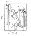
- Figure 1 is an image forming apparatus of the first embodiment.
- a latent image is formed on a photo conductor 35 of an image forming section 34 by a writing device 33 based on an image data read by a reading device 32 above a main body 31.
- a toner goes onto the latent image from a developing device 36, and then a visible image is formed.
- a sheet feed apparatus 1 is disposed below the main body 31 .
- a sheet feed roller 54 and conveying rollers 7 convey a sheet P through a passage 37 to the photo conductor 35, and then the visible image transfers the sheet P.
- the sheet P goes toward a fixing device 38, and then the fixing device 38 fixes the visible image on the sheet P.
- output rollers 39 output the sheet P to an output storing tray 40.
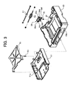
- the sheet feed apparatus 1 includes a bottom board 51 stacking sheets as a sheet stacking member, a sheet feed roller 54 feeding the sheet on the bottom board 51, a tilt member 56 having a tilt face 56a arranged to touch the edge of the sheet. The sheets are separated in the tilt face 56a.
- the whole tilt member 56 is formed from polybutylene terephthalate (PBT) or polyethylene (PE). It is possible that only the tilt face 56a and a contact face 56b contacting the sheet feed roller 54 may be formed from PBT or PE.
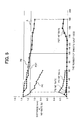
- FIG. 3 is a chart of experimental results of different materials used in the sheet feed apparatus of Figure 2. Experiment conditions were as follows:
- the line A (1.16mm) is designated as a non-feed line.
- the non-feed line is determined empirically as the point where significant non-feeds occur if the material is formed from PC. This line corresponds to 0.2mm wear from an initial thickness of material.
- the experiment showed that a tilt member formed from PE or PBT demonstrated superior wear resistance because tilt members made of these materials did not fall bellow the non-feed line A until about 110,000 sheets have been printed.
- a tilt member formed from PC did not demonstrate good wear resistance as the tilt member fell below the non-feed line when about 10,000 sheets were printed. Therefore, experimental results showed that superior performance is achieved if at least the tilt face 56a and the contact face 56b are formed from PE or PBT.
- FIG. 5 also gives Non-Feed (NF) rates for the 3 tested tilt members.
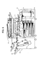
- Figure 6 is a diagram of a second embodiment of an image forming apparatus.
- the image forming apparatus of the second embodiment includes a large sheet feed apparatus 10 in the right side lower part.
- the large sheet feed apparatus 10 includes a loading board 23 configured to stack a large number of sheets, a tilt member 56 having a tilt face and a contact face, a sheet feed roller 54 feeding a sheet on the stacking board 23. The sheets are separated in the tilt face of the tilt member 56.
- the image forming apparatus also includes a main body 2, an automatic document feeder (ADF) 20, and a finisher 30 having a stapler device 21.
- ADF automatic document feeder
- a paper feed apparatus 22 including plural sheet feed cassettes is disposed in the lower part of the main body 2.
- the sheet is fed from the large sheet feed apparatus 10 or a sheet feed cassette of the sheet feed apparatus 22.
- the sheet is conveyed by rollers, and then the sheet reaches a registration roller 3.
- an image on a photo conductor 18 is transferred to the sheet by a transfer belt 4, and then a fixing device 5 fixes the image on the sheet.
- the image side of the sheet is input face-up. In this mode of operations, the sheet is conveyed to the left shown in the Figure 6.
- An entrance sensor 11 detects the image side of the sheet, and an upper divergence nail 19 and a lower divergence nail 8 are not engaged. Then, the sheet is output to the output tray 25 through the finisher 30.
- the image side of the sheet is input face-down.
- the upper divergence nail 19 and the lower divergence nail 8 each rotate so that the sheet is led to an upper turning-over path 32 or a lower turning-over path 29.
- either the upper divergence nail 19 or the lower divergence nail 8 may move first. However, the upper divergence nail 19 and the lower divergence nail 8 may move alternately to prevent the sheets from interfering with each other.
- the sheet is sent to the upper turning-over path 32. Then, a switchback roller 13 conveys the sheet. When a turning-over sensor 12 detects an end of the sheet, the switchback roller 13 turns in reverse. Then, the sheet returns to a divergence position and then the sheet is output to the output tray 25 through the finisher 30.
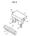
- the tilt member 66 of the second embodiment includes a tilt part 67 and a support part 68.
- the tilt part 67 includes a tilt face 67a where the sheet contacts the tilt part 67 and a contact face 67b contacting the sheet feed roller 54.
- the tilt part 67 is formed from a metal or other high durability material.
- the tilt part 67 is formed from aluminum (A1), poly-ether-ether-ketone (PEEK), polyimide (PI), or an alloy that includes polyimide (PAI).
- the tilt member 66 also includes a support member 68 that may be formed of the same material as the tilt part 67 or may be formed from a lower-cost material, for example, ABS resin, polyacetal (POM), polybutylene terephthalate (PBT), or polycarbonate (PC).
- the tilt member 66 includes two ribs 68a in order for the tilt member 66 to be guided by guiding rails formed in a main body. Further, the tilt member 66 includes two hooks 68b for limiting the range of the movement of the tilt member 66.
- Figure 9 is chart of experimental results of different materials used in the large sheet feed apparatus of Figure 6.
- the tilt member is now formed from one of aluminum (Al), poly-ether-ether-ketone (PEEK), polyimide (PI), or an alloy that includes polyimide (PAI).
- Al aluminum
- PEEK poly-ether-ether-ketone
- PI polyimide
- PAI alloy that includes polyimide
- the line B is the empirically determined non-feed line corresponding to 0.2mm wear from the initial thickness.
- a glass fiber or another material can be added to the PBT, PE, Metal, PEEK, or PI.
- alloys that include PBT, PE, Metal, PEEK, or PI can also be used.
Landscapes
- Engineering & Computer Science (AREA)
- Mechanical Engineering (AREA)
- Sheets, Magazines, And Separation Thereof (AREA)
Abstract
Description
In conventional systems, a sheet feed apparatus includes a feed roller contacting a tilt member with a separation means. However, in the conventional sheet feed apparatus there is problem in that the surface of the tilt member is easily worn or otherwise damaged when receiving a load by friction caused through contact with the feed roller. Once worn, the sheets are not consistently fed from the sheet feed apparatus, leading to missed pages, jammed pages, or other operational deficiencies. What is desirable, as discovered by the present inventors, is a sheet feed apparatus where the surface of the tilt member is not easily damaged from the friction associated with feeding sheets.
a
wherein the means for separating individual sheets with a
a
a
56 comprises at least one of polybutylene terephthalate (PBT); polyethylene (PE); metal; poly-ether-ether-ketone (PEEK); and polyimide (PI).
a
a
a
a
The sheet P goes toward a fixing
As shown in Figure 2, the
In this embodiment, the
As shown in Figure 4, the
Figure 5 is a chart of experimental results of different materials used in the sheet feed apparatus of Figure 2. Experiment conditions were as follows:
- Materials of the tilt member - polycarbonate (PC), polybutylene terephthalate (PBT), polyethylene (PE)
- A pressing force of the tilt member pushing the sheet feed roller - 2.99N
- Speed when the sheet feed roller is separating sheets - 133.5mm/sec
- Speed after the sheet feed roller is separating the sheets - 66.75mm/sec
- A pressing force when the sheet feed roller is feeding sheet - Minimum 3.90N, Max 5.90N
- An angle of the tilt side to the sheet - 60°
- Timing of measuring a wear of the tilt side - 0-60000 sheets; every 5000 sheets; 60000-180,000 sheets; every 10,000 sheets
- Kind of paper-LT size
- Interval of experiment - 5000 sheets per day
- Distance between the
contact face 56a and aplane face 56g - 1.36mm
Figure 6 is a diagram of a second embodiment of an image forming apparatus. The image forming apparatus of the second embodiment includes a large
The image forming apparatus also includes a
When an image is formed on one side of a sheet, the sheet is fed from the large
In one simplex mode of operations (i.e., single-sided copying), the image side of the sheet is input face-up. In this mode of operations, the sheet is conveyed to the left shown in the Figure 6. An
In another simplex mode of operations, the image side of the sheet is input face-down. In this mode of operations, the upper divergence nail 19 and the
If the upper divergence nail 19 moves first, the sheet is sent to the upper turning-over
In a duplex mode of operations (i.e., two-sided copying), the image forming process is the same as the simplex mode of operations. When a
As shown in Figures 7 and 8, the
Figure 9 is chart of experimental results of different materials used in the large sheet feed apparatus of Figure 6. In these experiments, conditions were similar to the conditions of the previous experiment except that the tilt member is now formed from one of aluminum (Al), poly-ether-ether-ketone (PEEK), polyimide (PI), or an alloy that includes polyimide (PAI). In Figure 9, the line B is the empirically determined non-feed line corresponding to 0.2mm wear from the initial thickness.
These experiments showed that a tilt member formed from the above-listed material has excellent wear resistance because the tilt member doesn't fall bellow the non-feed line until about 1,000,000 sheets. Therefore, these experiments show that the second embodiment has better wear resistant than the first embodiment and may be more cost-effective for use in tilt members in high-duty cycle, large sheet feed apparatus.
In other embodiments demonstrating excellent wear resistance, a glass fiber or another material can be added to the PBT, PE, Metal, PEEK, or PI. In yet other embodiments; alloys that include PBT, PE, Metal, PEEK, or PI can also be used.
It will be obvious to those having skill in the art that many changes may be made in the above-described details of the preferred embodiments of the present invention. The scope of the present invention, therefore, should be determined by the following claims.
Claims (18)
- A sheet feed apparatus 1, comprising:means 54 for sequentially feeding sheets to an imaging device; andmeans for separating individual sheets with a tilt member 56 comprising a tilt face 56a and a contact face 56b each comprising one or more of polybutylene terephthalate (PBT), polyethylene (PE), metal, poly-ether-ether-ketone (PEEK), and polyimide (PI).
- The sheet feed apparatus of claim 1,
wherein the means 54 for sequentially feeding sheets into an imaging device is a sheet feed roller 54 in pressing contact with an uppermost sheet of a plurality of sheets; and
wherein the means for separating individual sheets with a tilt member 56 is opposing the sheet feed roller 54, said tilt member 56 including
a contact face 56b in pressing contact with the sheet feed roller 54, and
a tilt face 56a in contact with an edge of the uppermost sheet, said tilt face and said contact face each comprising one or more of polybutylene terephthalate (PBT), polyethylene (PE), metal, poly-ether-ether-ketone (PEEK), and polyimide (PI). - The sheet feed apparatus according to claim 1 or 2, wherein said tilt face and said contact face each comprise polybutylene terephthalate (PBT).
- The sheet feed apparatus according to claim 1 or 2, wherein said tilt face and said contact face each comprise polyethylene (PE).
- The sheet feed apparatus according to claim 1 or 2, wherein said tilt face and said contact face each comprise metal.
- The sheet feed apparatus according to claim 1 or 2, wherein said tilt face and said contact face each comprise poly-ether-ether-ketone (PEEK).
- The sheet feed apparatus according to claim 1 or 2, wherein said tilt face and said contact face each comprise polyimide (PI).
- The sheet feed apparatus according to claim 1 or 2, wherein said entire tilt member 56 comprises at least one of polybutylene terephthalate (PBT); polyethylene (PE); metal; poly-ether-ether-ketone (PEEK); and polyimide (PI).
- The sheet feed apparatus according to claim 1 or 2, wherein said tilt face or contact face further comprise another wear resistance material, preferably glass fibers.
- An image forming apparatus, comprising:an image forming section 34; anda sheet feed apparatus according to one of claims 1 to 8 aligned to feed a sheet to the image forming section.
- The image forming apparatus of claim 10, comprising
a sheet feed roller 54 in pressing contact with an uppermost sheet of a plurality of sheets, and
a tilt member 56 opposing the sheet feed roller 54, said tilt member including
a contact face 56b in pressing contact with the sheet feed roller 54, and
a tilt face 56a in contact with an edge of the uppermost sheet, said tilt face and said contact face each comprising one or more of polybutylene terephthalate (PBT), polyethylene (PE), metal, poly-ether-ether-ketone (PEEK), and polyimide (PI). - The image forming apparatus according to claim 10 or 11, wherein said tilt face and said contact face each comprise or may even consist of one of polybutylene terephthalate (PBT), polyethylene (PE), metal, poly-ether-ether-ketone (PEEK) or polyimide (PI).
- The image forming apparatus according to claim 10 or 11, wherein said tilt face and said contact face each comprise or may even or consist of mixtures of two or more of polybutylene terephthalate (PBT), polyethylene (PE), metal, poly-ether-ether-ketone (PEEK), and polyimide (PI).
- The image forming apparatus according to claim 10 or 11, wherein said entire tilt member 56 comprises or may even consist of at least one of polybutylene terephthalate (PBT); polyethylene (PE); metal; poly-ether-ether-ketone (PEEK); and polyimide (PI).
- The image forming apparatus according to one of claims 10 to 14, wherein said tilt member 56 further comprises:a support member comprising at least one of ABS resin; polyacetal (POM); polybutylene terephthalate (PBT); and polycarbonate (PC).
- The image forming apparatus according to one of claims 10 to 14, wherein said tilt face and / or said contact face further comprise another wear resistance material, preferably glass fibers.
- Use of a face in a sheet separator tilt member of a sheet feed apparatus, said face comprising one or more of polybutylene terephthalate (PBT), polyethylene (PE), metal, poly-ether-ether-ketone (PEEK), and polyimide (PI), and said face being at least one of a contact face 56b and a tilt face 56a.
- A method for feeding sheets to an image forming section 34 of an imaging device, comprising:separating individual sheets with a tilt member 56 comprising a tilt face 56a and a contact face 56b each comprising one or more of polybutylene terephthalate (PBT), polyethylene (PE), metal, poly-ether-ether-ketone (PEEK), and polyimide (PI).
Applications Claiming Priority (2)
| Application Number | Priority Date | Filing Date | Title |
|---|---|---|---|
| JP2002291810A JP2004123341A (en) | 2002-10-04 | 2002-10-04 | Feeding device and image forming apparatus having the same |
| JP2002291810 | 2002-10-04 |
Publications (2)
| Publication Number | Publication Date |
|---|---|
| EP1405806A2 true EP1405806A2 (en) | 2004-04-07 |
| EP1405806A3 EP1405806A3 (en) | 2004-05-06 |
Family
ID=31987198
Family Applications (1)
| Application Number | Title | Priority Date | Filing Date |
|---|---|---|---|
| EP03021672A Withdrawn EP1405806A3 (en) | 2002-10-04 | 2003-09-29 | Sheet feeding apparatus and image forming apparatus |
Country Status (4)
| Country | Link |
|---|---|
| US (1) | US7469889B2 (en) |
| EP (1) | EP1405806A3 (en) |
| JP (1) | JP2004123341A (en) |
| CN (1) | CN100391814C (en) |
Families Citing this family (8)
| Publication number | Priority date | Publication date | Assignee | Title |
|---|---|---|---|---|
| DE60123712T2 (en) * | 2000-08-08 | 2007-08-16 | Ricoh Co., Ltd. | Sheet feeding method and apparatus for an image forming apparatus |
| JP4264747B2 (en) * | 2005-02-21 | 2009-05-20 | ブラザー工業株式会社 | Image recording device |
| JP5212626B2 (en) * | 2008-07-02 | 2013-06-19 | セイコーエプソン株式会社 | Conveying device, recording device |
| JP2010030768A (en) * | 2008-07-30 | 2010-02-12 | Seiko Epson Corp | Paper feeding device and recording device |
| JP4962558B2 (en) * | 2009-12-28 | 2012-06-27 | ブラザー工業株式会社 | Sheet feeding device |
| JP5450507B2 (en) * | 2011-05-12 | 2014-03-26 | 京セラドキュメントソリューションズ株式会社 | Paper feed mechanism and image forming apparatus having the same |
| JP2015196570A (en) * | 2014-04-01 | 2015-11-09 | 株式会社リコー | Sheet feeding device, image formation device, and image reader |
| JP5775954B2 (en) * | 2014-06-26 | 2015-09-09 | 京セラドキュメントソリューションズ株式会社 | Conveying device and image forming apparatus incorporating the conveying device |
Family Cites Families (19)
| Publication number | Priority date | Publication date | Assignee | Title |
|---|---|---|---|---|
| US4150181A (en) * | 1977-07-01 | 1979-04-17 | Xerox Corporation | Fixing method using polysiloxane-fluorocarbon blends as release agents |
| DE68917612T2 (en) * | 1988-02-09 | 1995-01-12 | Canon Kk | Image fixing device. |
| JPH0255634A (en) | 1988-08-22 | 1990-02-26 | Nippon Concrete Ind Co Ltd | Knitting method for reinforcing bar cage for concrete pole |
| WO1994001495A1 (en) * | 1992-07-08 | 1994-01-20 | Kawasaki Chemical Holding Co. | Elastomer toughened, wear resistant compositions |
| JPH0667480A (en) | 1992-08-19 | 1994-03-11 | Fujitsu Ltd | Printer |
| JP3448097B2 (en) * | 1994-05-19 | 2003-09-16 | ブラザー工業株式会社 | Paper feeder |
| JPH08234531A (en) | 1995-02-24 | 1996-09-13 | Ricoh Co Ltd | Color image forming device |
| JPH10139197A (en) | 1996-11-01 | 1998-05-26 | Canon Aptecs Kk | Paper feeding device and image forming device equipped with the same |
| JPH1124507A (en) | 1997-07-07 | 1999-01-29 | Ricoh Co Ltd | Image forming device |
| JPH11217136A (en) * | 1997-11-20 | 1999-08-10 | Fuji Photo Film Co Ltd | Guide plate and picture record medium carrying device using the same |
| US5997965A (en) * | 1998-03-18 | 1999-12-07 | Ntn Corporation | Stripping finger |
| US6059483A (en) * | 1998-08-03 | 2000-05-09 | Ford Motor Company | Sealed joint for a multi-component injection molded automotive lamp assembly |
| US6280055B1 (en) * | 1998-09-28 | 2001-08-28 | Andy Merko | Light modifier |
| US6260840B1 (en) * | 1998-10-14 | 2001-07-17 | Canon Kabushiki Kaisha | Sheet feeding apparatus, image forming apparatus having the same and image reading apparatus having the same |
| JP4121209B2 (en) * | 1999-02-26 | 2008-07-23 | 東北リコー株式会社 | Paper feeding device in image forming apparatus |
| DE60123712T2 (en) | 2000-08-08 | 2007-08-16 | Ricoh Co., Ltd. | Sheet feeding method and apparatus for an image forming apparatus |
| JP2002068511A (en) * | 2000-09-01 | 2002-03-08 | Sumitomo Rubber Ind Ltd | Paper sheets double feed prevention member |
| JP2002131091A (en) | 2000-10-27 | 2002-05-09 | Ricoh Co Ltd | Relative speed detection device, toner image transfer device, image forming device |
| US6688590B2 (en) * | 2000-12-08 | 2004-02-10 | Lexmark International, Inc. | Dual tray printer with single drive shaft and dual media picks |
-
2002
- 2002-10-04 JP JP2002291810A patent/JP2004123341A/en active Pending
-
2003
- 2003-07-03 US US10/611,901 patent/US7469889B2/en not_active Expired - Fee Related
- 2003-09-15 CN CNB031588638A patent/CN100391814C/en not_active Expired - Fee Related
- 2003-09-29 EP EP03021672A patent/EP1405806A3/en not_active Withdrawn
Also Published As
| Publication number | Publication date |
|---|---|
| US20040065993A1 (en) | 2004-04-08 |
| CN1490234A (en) | 2004-04-21 |
| JP2004123341A (en) | 2004-04-22 |
| CN100391814C (en) | 2008-06-04 |
| US7469889B2 (en) | 2008-12-30 |
| EP1405806A3 (en) | 2004-05-06 |
Similar Documents
| Publication | Publication Date | Title |
|---|---|---|
| US7862026B2 (en) | Sheet post-processing apparatus and sheet post-processing method | |
| US6845228B2 (en) | Sheet treating apparatus and image forming apparatus | |
| US20030038989A1 (en) | Image reading apparatus | |
| US5974290A (en) | Image forming apparatus having sheet guide members openable for removing a jammed sheet | |
| CN1003364B (en) | Paper feeding device | |
| US7469889B2 (en) | Sheet feeding apparatus and image forming apparatus | |
| US7342694B2 (en) | Image reading device | |
| US6353727B1 (en) | Image forming apparatus having staple processing section | |
| US5269505A (en) | Friction retard feeder with a stepped retard pad | |
| JP2001130769A (en) | Sheet feeding device and image processing device | |
| JP2007314258A (en) | Paper feeding device and image forming apparatus | |
| JP4240692B2 (en) | Automatic sheet material transfer device | |
| JP2003252468A (en) | Paper feeder and image forming apparatus | |
| JP2003069790A (en) | Image reading apparatus and image forming apparatus provided with this apparatus | |
| JP2007070003A (en) | Sheet feeding apparatus, image reading apparatus, and image forming apparatus | |
| US20240286856A1 (en) | Paper sheet processing apparatus | |
| JP2001048403A (en) | Image forming apparatus | |
| JPH02178133A (en) | Paper feeder | |
| JP2008179461A (en) | Sheet stacking device and image forming device | |
| JP2719590B2 (en) | Paper feeder | |
| JP2805783B2 (en) | Paper feeder | |
| JP3618994B2 (en) | Image forming apparatus | |
| JP3647249B2 (en) | Sheet conveying apparatus, image forming apparatus, image reading apparatus, and image processing apparatus including these | |
| JP2020040765A (en) | Sheet feeding apparatus and image forming apparatus | |
| JPH11255396A (en) | Image forming apparatus and duplex printing unit |
Legal Events
| Date | Code | Title | Description |
|---|---|---|---|
| PUAI | Public reference made under article 153(3) epc to a published international application that has entered the european phase |
Free format text: ORIGINAL CODE: 0009012 |
|
| PUAL | Search report despatched |
Free format text: ORIGINAL CODE: 0009013 |
|
| AK | Designated contracting states |
Kind code of ref document: A2 Designated state(s): AT BE BG CH CY CZ DE DK EE ES FI FR GB GR HU IE IT LI LU MC NL PT RO SE SI SK TR |
|
| AX | Request for extension of the european patent |
Extension state: AL LT LV MK |
|
| AK | Designated contracting states |
Kind code of ref document: A3 Designated state(s): AT BE BG CH CY CZ DE DK EE ES FI FR GB GR HU IE IT LI LU MC NL PT RO SE SI SK TR |
|
| AX | Request for extension of the european patent |
Extension state: AL LT LV MK |
|
| 17P | Request for examination filed |
Effective date: 20041021 |
|
| AKX | Designation fees paid |
Designated state(s): DE ES FR GB IT NL |
|
| 17Q | First examination report despatched |
Effective date: 20050915 |
|
| STAA | Information on the status of an ep patent application or granted ep patent |
Free format text: STATUS: THE APPLICATION HAS BEEN WITHDRAWN |
|
| 18W | Application withdrawn |
Effective date: 20090525 |