EP1405793B1 - Packaging container - Google Patents
Packaging container Download PDFInfo
- Publication number
- EP1405793B1 EP1405793B1 EP03256134A EP03256134A EP1405793B1 EP 1405793 B1 EP1405793 B1 EP 1405793B1 EP 03256134 A EP03256134 A EP 03256134A EP 03256134 A EP03256134 A EP 03256134A EP 1405793 B1 EP1405793 B1 EP 1405793B1
- Authority
- EP
- European Patent Office
- Prior art keywords
- closure panels
- side walls
- main body
- panels
- closure
- Prior art date
- Legal status (The legal status is an assumption and is not a legal conclusion. Google has not performed a legal analysis and makes no representation as to the accuracy of the status listed.)
- Expired - Lifetime
Links
- 238000004806 packaging method and process Methods 0.000 title claims description 26
- 238000003780 insertion Methods 0.000 claims description 2
- 230000037431 insertion Effects 0.000 claims description 2
- 238000005520 cutting process Methods 0.000 description 11
- 238000004049 embossing Methods 0.000 description 9
- 239000000463 material Substances 0.000 description 9
- 239000012636 effector Substances 0.000 description 5
- 238000007373 indentation Methods 0.000 description 3
- 239000000853 adhesive Substances 0.000 description 2
- 230000000712 assembly Effects 0.000 description 2
- 238000000429 assembly Methods 0.000 description 2
- 239000005022 packaging material Substances 0.000 description 2
- 239000011087 paperboard Substances 0.000 description 2
- JOYRKODLDBILNP-UHFFFAOYSA-N Ethyl urethane Chemical compound CCOC(N)=O JOYRKODLDBILNP-UHFFFAOYSA-N 0.000 description 1
- 230000004913 activation Effects 0.000 description 1
- 230000001070 adhesive effect Effects 0.000 description 1
- 238000005452 bending Methods 0.000 description 1
- 230000015572 biosynthetic process Effects 0.000 description 1
- 238000010276 construction Methods 0.000 description 1
- 239000012611 container material Substances 0.000 description 1
- 230000009977 dual effect Effects 0.000 description 1
- 238000009434 installation Methods 0.000 description 1
- 238000004519 manufacturing process Methods 0.000 description 1
- 238000000034 method Methods 0.000 description 1
- 239000012858 resilient material Substances 0.000 description 1
- 239000000565 sealant Substances 0.000 description 1
- 238000007789 sealing Methods 0.000 description 1
- 230000003313 weakening effect Effects 0.000 description 1
- 239000002023 wood Substances 0.000 description 1
Images


Classifications
-
- B—PERFORMING OPERATIONS; TRANSPORTING
- B65—CONVEYING; PACKING; STORING; HANDLING THIN OR FILAMENTARY MATERIAL
- B65D—CONTAINERS FOR STORAGE OR TRANSPORT OF ARTICLES OR MATERIALS, e.g. BAGS, BARRELS, BOTTLES, BOXES, CANS, CARTONS, CRATES, DRUMS, JARS, TANKS, HOPPERS, FORWARDING CONTAINERS; ACCESSORIES, CLOSURES, OR FITTINGS THEREFOR; PACKAGING ELEMENTS; PACKAGES
- B65D5/00—Rigid or semi-rigid containers of polygonal cross-section, e.g. boxes, cartons or trays, formed by folding or erecting one or more blanks made of paper
- B65D5/42—Details of containers or of foldable or erectable container blanks
- B65D5/64—Lids
- B65D5/66—Hinged lids
- B65D5/6626—Hinged lids formed by folding extensions of a side panel of a container body formed by erecting a "cross-like" blank
- B65D5/6629—Hinged lids formed by folding extensions of a side panel of a container body formed by erecting a "cross-like" blank the lid being formed by two mating halves joined to opposite edges of the container body
-
- B—PERFORMING OPERATIONS; TRANSPORTING
- B31—MAKING ARTICLES OF PAPER, CARDBOARD OR MATERIAL WORKED IN A MANNER ANALOGOUS TO PAPER; WORKING PAPER, CARDBOARD OR MATERIAL WORKED IN A MANNER ANALOGOUS TO PAPER
- B31B—MAKING CONTAINERS OF PAPER, CARDBOARD OR MATERIAL WORKED IN A MANNER ANALOGOUS TO PAPER
- B31B50/00—Making rigid or semi-rigid containers, e.g. boxes or cartons
- B31B50/14—Cutting, e.g. perforating, punching, slitting or trimming
- B31B50/20—Cutting sheets or blanks
Definitions
- the present invention is directed to a packaging container. More particularly, the present invention pertains to a packaging container having self-formed end closures, created from a single piece of material.
- Packaging for lengthy items takes many forms.
- One construction includes a pair of corrugated, laminated paperboard top and bottom U-shaped channels configured for one to fit within the other.
- Most packages formed in this manner require separated end closures or caps, usually manufactured from cardboard or wood. These caps generally are stapled to adjacent package walls. Not only does this method necessitate close-fit manufacturing, but it is also very cumbersome at installation, and may cause content damage due to incompletely formed or off-positioned staples.
- FR2642404 discloses a package having a self-adhesive closure.
- one of the top and bottom U-shaped channels has a notch cut into opposing side walls of the "U,” so that the "U" portion may be folded over at a 90 degree angle.
- channel ends are closed by the folded base portion and the side walls of the "U,”, which are folded over adjacent side walls.
- tape or a like strip-type adhesive sealant must be extended over the flaps that then are folded over the adjacent side walls. Even though a seal may be formed, however, openings may remain at the juncture of the folded-over base portion and the cover portion, seriously weakening the package.
- This design is disclosed in U.S. Pat. No. 4,976,374, which is incorporated herein by reference.
- Another existing packaging container resolves the above-referenced problems by providing a packaging container in which the entirety of the end closure is formed from the packaging material itself.
- the container base unit which forms end closures for the packaging container, features mitered corners. These mitered corners require complex die-cutting with mirrored tools, and mandatory strapping at specific positions to restrain the miter flaps.
- the container's end closures meet or overlap along the container's main body portion, providing a high degree of structural strength and package integrity while requiring only a central tape sealing.
- the container may be prepared simply by making two straight saw-cuts on each package end.
- a packaging container includes a preformed, rigid unit of U-shaped cross-section having a main body portion with a generally flat bottom wall and opposing side walls.
- the unit forms two end closures, at each end of the packaging container.
- Each end closure is formed from a first closure panel extending from and adjacent to an end of the main body portion, and a second closure panel extending from and adjacent to an end of a first closure panel.
- the main body portion and the first closure panels are separated from one another by first fold lines.
- the first closure panels and the second closure panels are separated from one another by second fold lines.
- the package material although defined as having a U-shaped cross-section is, in fact, formed from a material having a channel-like or squared U-shape having a flat or near-flat bottom wall.
- the corners may be formed having a radius of curvature (i.e., rounded) or they may be formed having relatively sharp angles.
- the container material is referred to as "U-shaped".
- the main body portion side walls have straight-cut square corners adjacent to the first closure panels, and the first closure panels side walls have first straight-cut square corners adjacent to the main body.
- the first closure panels side walls additionally have second straight-cut square corners adjacent to the second closure panels, and the second closure panels side walls have straight-cut square corners adjacent to the first closure panels.
- the first closure panels are configured for folding generally perpendicular to the main body bottom wall
- the second closure panels are configured for folding generally perpendicular to the first closure panels and generally parallel to the main body bottom wall.
- the main body side walls are about equal in height to the first and second closure panels side walls.
- the first and second closure panels side walls are configured for insertion inside the main body side walls when the end closures are formed.
- each second closure panel is at least half as long as the main body portion.
- the packaging container is formed in an U-shaped cross-section.
- the packaging container is formed from laminated paperboard material.
- the packaging container includes a main body portion 12, first closure panels 14, and second closure panels 16.
- the straight-cut first and second closure panels 14, 16 are formed from an extension of the main body portion 12.
- the main body portion 12 has a generally flat bottom wall 18 and upstanding side walls 20.
- the first and second closure panels 14, 16 also have bottom walls 22, 24 and upstanding side walls 26, 28.
- U-shaped the package is actually formed from a channel-like structure having a flat or near-flat bottom wall 18.
- the first closure panels 14 are formed adjacent to and at either end of the main body portion 12.
- the side wails 26 of the first closure panels 14 have first straight-cut corners 30.
- the main body side walls 20 also have straight-cut corners 32, immediately adjacent to the first panels' straight-cut corners 30.
- First fold lines or creases 34 can be formed between the main body bottom wail 18 and the first closure panels' bottom walls 22 at the junctures of the straight-cut corners 30, 32 to facilitate folding.
- the second closure panels 16 are adjacent to the first closure panels 14.
- the second closure panels 16 are separated from the first panels 14 by second fold or crease lines 36 formed between the first closure panels' bottom walls 22 and the second closure panels' bottom walls 24, parallel to the first fold lines 34.
- the side walls 28 of the second closure panels 16 include straight-cut corners 38 at the junctures with the first closure panels 14.
- the side walls 26 of the first closure panels 14 include second straight-cut corners 40 adjacent to the second closure panels 16.
- the height h 20 of the main body side walls 20 is about equal to the heights h 26 , h 28 of the first closure panels side walls 26 and the second closure panels side walls 28.
- assembling the package 10 is straightforward and readily carried out.
- the package 10 is placed on a surface, with the main body 12, and the first and second closure panels 14, 16 laid out flat.
- the articles to be packaged are placed in the main body portion 12.
- the first panels 14 are then folded upwardly, so that the first panels 14 are perpendicular to the bottom wall 18 of the main body portion 12.
- As the first panels 14 are folded their side walls 26 can be inserted between the main body side walls 20.
- the second panels 16 are then folded over, perpendicular to the first panels 14, so that the bottom walls 24 of the second panels 16 lie parallel to the bottom wall 18 of the main body portion 12.
- As the second panels 16 are folded their side walls 28 can be inserted between the side walls 26 of the first panels 14.
- FIG. 3 shows the package 10 fully assembled, with one second panel 1 6a overlapping the other second panel 16b.
- the device 104 includes a frame 106, having an upper embossing/guide assembly 108 and lower cutting assembly 110 mounted thereto.
- An exemplary U-shaped unit 112 with vertical side walls 114, 116 to be cut is positioned between the upper 108 and lower 110 assemblies.
- the unit is supported by a bench or conveyor mechanism B.
- the unit 112 is centered and restricted from lateral movement by an adjustable centering arm 118, positioned outside of the cutting plane 120.
- the upper assembly 108 includes a two-step air cylinder 122, tooled with dual embossing end-effectors 124, 126.
- a depth adjustment such as the exemplary threaded element 128 vertically adjusts the position of the cylinder 122 to accommodate varying unit depths.
- the lower assembly 110 includes an air cylinder 130, includes two pairs of notching blades 132, 134 and an embossing return pad 136.
- the embossing return pad 136 is made of a resilient material.
- the embossing return pad 136 is made of urethane.
- both the upper 108 and lower 110 assemblies are clear of the unit 112.
- the upper air cylinder 122 extends to a first pre-programmed depth 138, causing the end-effectors 124, 126 to come into contact with an internal bottom wall 140 of the unit 112.
- the end-effectors 124, 126 provide support for the crate bottom wall 140 and loosely fits between the vertical side walls 114, 116.
- the lower air cylinder 130 extends, causing the two pairs of notching blades 132, 134 to cut completely through the crate's vertical side wails 114, 116, leaving the crate's bottom wall 140 intact.
- the end-effectors 124, 126 can include guides 127 formed as channels therein. The guides 127 provide a centering means to assure that the blades 132, 134 remain straight during the cutting cycle.
- the two pairs of notching blades 132, 134 remain raised, causing the crate's bottom wall 140 to rest on the embossing return pad 136 (as seen in FIG. 5).
- the upper air cylinder 122 extends to a second pre-programmed depth 142.
- the end-effectors 124, 126 therefore embed into the crate internal bottom wall 140, deforming the material into the embossing return pad 136.
- a resulting indentation 144 compresses the crate's bottom wall 140 along future bending lines, facilitating the formation of packaging containers.
- both the upper 108 and lower 110 segments return to their original positions, as in FIG. 4.
- the indentations form a region at which the material will more readily fold to form the container 10, 210, 410.
- the present device 104 can be used with container units 112 having a wide variety of wall 114, 116 heights with minimal to no adjustment. This increases the flexibility of the packager vis-A-vis selecting a proper package based upon the articles to be packaged, rather than a package for which the device is configured or designed.
- cutting rather than sawing the material provides a "cleaner" cut with respect to the ends of the material as well as debris that may be created during the cutting operation. It has further been found that the cutting blades 132, 134, moving toward the unattached (e.g., free-) ends of the walls 114, 116 prevents collapse of the walls 114, 116, regardless of the material thickness, during the cutting operation.
Abstract
Description
- The present invention is directed to a packaging container. More particularly, the present invention pertains to a packaging container having self-formed end closures, created from a single piece of material.
- Packaging for lengthy items takes many forms. One construction includes a pair of corrugated, laminated paperboard top and bottom U-shaped channels configured for one to fit within the other. Most packages formed in this manner require separated end closures or caps, usually manufactured from cardboard or wood. These caps generally are stapled to adjacent package walls. Not only does this method necessitate close-fit manufacturing, but it is also very cumbersome at installation, and may cause content damage due to incompletely formed or off-positioned staples.
- FR2642404 discloses a package having a self-adhesive closure.
- In another variety of packaging container, one of the top and bottom U-shaped channels has a notch cut into opposing side walls of the "U," so that the "U" portion may be folded over at a 90 degree angle. In such a configuration, channel ends are closed by the folded base portion and the side walls of the "U,", which are folded over adjacent side walls. To seal such a package, tape or a like strip-type adhesive sealant must be extended over the flaps that then are folded over the adjacent side walls. Even though a seal may be formed, however, openings may remain at the juncture of the folded-over base portion and the cover portion, seriously weakening the package. This design is disclosed in U.S. Pat. No. 4,976,374, which is incorporated herein by reference.
- Another existing packaging container, disclosed in U.S. Pat. No. 6,382,447, resolves the above-referenced problems by providing a packaging container in which the entirety of the end closure is formed from the packaging material itself. However, the container base unit, which forms end closures for the packaging container, features mitered corners. These mitered corners require complex die-cutting with mirrored tools, and mandatory strapping at specific positions to restrain the miter flaps.
- Accordingly, there exists a need for a single-piece packaging container cut without miters in which the entirety of the end closures are formed from the packaging material itself. Desirably, the container's end closures meet or overlap along the container's main body portion, providing a high degree of structural strength and package integrity while requiring only a central tape sealing. Such a configuration allows for no gaps at its closure locations. Most desirably, the container may be prepared simply by making two straight saw-cuts on each package end.
- A packaging container includes a preformed, rigid unit of U-shaped cross-section having a main body portion with a generally flat bottom wall and opposing side walls. The unit forms two end closures, at each end of the packaging container. Each end closure is formed from a first closure panel extending from and adjacent to an end of the main body portion, and a second closure panel extending from and adjacent to an end of a first closure panel. The main body portion and the first closure panels are separated from one another by first fold lines. The first closure panels and the second closure panels are separated from one another by second fold lines.
- For purposes of the present disclosure, the package material, although defined as having a U-shaped cross-section is, in fact, formed from a material having a channel-like or squared U-shape having a flat or near-flat bottom wall. The corners may be formed having a radius of curvature (i.e., rounded) or they may be formed having relatively sharp angles. However, again, for purposes of the present disclosure, the container material is referred to as "U-shaped".
- The main body portion side walls have straight-cut square corners adjacent to the first closure panels, and the first closure panels side walls have first straight-cut square corners adjacent to the main body. The first closure panels side walls additionally have second straight-cut square corners adjacent to the second closure panels, and the second closure panels side walls have straight-cut square corners adjacent to the first closure panels.
- The first closure panels are configured for folding generally perpendicular to the main body bottom wall, and the second closure panels are configured for folding generally perpendicular to the first closure panels and generally parallel to the main body bottom wall.
- In a preferred embodiment, the main body side walls are about equal in height to the first and second closure panels side walls. Preferably, the first and second closure panels side walls are configured for insertion inside the main body side walls when the end closures are formed. Most preferably, each second closure panel is at least half as long as the main body portion.
- These and other features and advantages of the present invention will be apparent from the following detailed description, in conjunction with the appended claims.
- Particular embodiments in accordance with this invention will now be described with reference to the accompanying drawings; in which:-
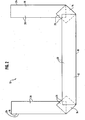
- FIG. 1 is a side view of an embodiment of the single-piece packaging container with straight-cut end closures constructed in accordance with the principles of the present invention, the container being shows with its first and second closure panels laid open, prior to folding and securing;
- FIG. 2 illustrates the folding in-progress of the end closures of FIG. 1;
- FIG. 3 is a bottom view of an embodiment of the packaging container, the container being shown in a fully constructed or assembled form and further shown with its second closure panels overlapping;
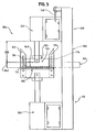
- FIG. 4 is a side view of a device for straight-cutting and embossing U-shaped packaging crates, the device being shown in its at-rest position;
- FIG. 5 illustrates the movements of the device of FIG. 4;
- FIG. 6 is an alternate side view of the device of FIG. 4, the device being shown in its at-rest position; and
- FIG. 7 illustrates an indentation in a packaging crate resulting from use of the device.
- Referring now to the figures and in particular FIG. 1, there is shown a
packaging container 10 embodying the principles of the present invention. The packaging container is formed in an U-shaped cross-section. Preferably, the packaging container is formed from laminated paperboard material. The packaging container includes amain body portion 12,first closure panels 14, andsecond closure panels 16. The straight-cut first andsecond closure panels main body portion 12. Themain body portion 12 has a generallyflat bottom wall 18 andupstanding side walls 20. The first andsecond closure panels bottom walls 22, 24 andupstanding side walls flat bottom wall 18. - The
first closure panels 14 are formed adjacent to and at either end of themain body portion 12. The side wails 26 of thefirst closure panels 14 have first straight-cut corners 30. The mainbody side walls 20 also have straight-cut corners 32, immediately adjacent to the first panels' straight-cut corners 30. First fold lines orcreases 34 can be formed between the mainbody bottom wail 18 and the first closure panels' bottom walls 22 at the junctures of the straight-cut corners - The
second closure panels 16 are adjacent to thefirst closure panels 14. Thesecond closure panels 16 are separated from thefirst panels 14 by second fold orcrease lines 36 formed between the first closure panels' bottom walls 22 and the second closure panels'bottom walls 24, parallel to thefirst fold lines 34. Theside walls 28 of thesecond closure panels 16 include straight-cut corners 38 at the junctures with thefirst closure panels 14. Theside walls 26 of thefirst closure panels 14 include second straight-cut corners 40 adjacent to thesecond closure panels 16. The height h20 of the mainbody side walls 20 is about equal to the heights h26, h28 of the first closurepanels side walls 26 and the second closurepanels side walls 28. - Referring to FIG. 2, assembling the
package 10 is straightforward and readily carried out. Thepackage 10 is placed on a surface, with themain body 12, and the first andsecond closure panels main body portion 12. Thefirst panels 14 are then folded upwardly, so that thefirst panels 14 are perpendicular to thebottom wall 18 of themain body portion 12. As thefirst panels 14 are folded, theirside walls 26 can be inserted between the mainbody side walls 20. Thesecond panels 16 are then folded over, perpendicular to thefirst panels 14, so that thebottom walls 24 of thesecond panels 16 lie parallel to thebottom wall 18 of themain body portion 12. As thesecond panels 16 are folded, theirside walls 28 can be inserted between theside walls 26 of thefirst panels 14. - FIG. 3 shows the
package 10 fully assembled, with one second panel 1 6a overlapping the othersecond panel 16b. - Referring now to FIGS. 4-6, there is shown a
device 104 for straight-cutting and embossing U-shapedpackaging container sections 10, 210, 410. Thedevice 104 includes aframe 106, having an upper embossing/guide assembly 108 andlower cutting assembly 110 mounted thereto. An exemplaryU-shaped unit 112 withvertical side walls unit 112 is centered and restricted from lateral movement by an adjustable centeringarm 118, positioned outside of the cuttingplane 120. - The
upper assembly 108 includes a two-step air cylinder 122, tooled with dual embossing end-effectors element 128 vertically adjusts the position of thecylinder 122 to accommodate varying unit depths. Thelower assembly 110 includes anair cylinder 130, includes two pairs of notchingblades embossing return pad 136. Preferably, theembossing return pad 136 is made of a resilient material. In a preferred embodiment, theembossing return pad 136 is made of urethane. - Referring now to FIG. 4, at the start of the cutting cycle, both the upper 108 and lower 110 assemblies are clear of the
unit 112. As a first step, following manual or automatic activation, theupper air cylinder 122 extends to a firstpre-programmed depth 138, causing the end-effectors internal bottom wall 140 of theunit 112. The end-effectors crate bottom wall 140 and loosely fits between thevertical side walls - Once the
device 104 senses that the first step is complete, thelower air cylinder 130 extends, causing the two pairs of notchingblades bottom wall 140 intact. As seen in FIG. 6, the end-effectors guides 127 formed as channels therein. Theguides 127 provide a centering means to assure that theblades blades bottom wall 140 to rest on the embossing return pad 136 (as seen in FIG. 5). Next, theupper air cylinder 122 extends to a secondpre-programmed depth 142. The end-effectors bottom wall 140, deforming the material into theembossing return pad 136. A resultingindentation 144, as see in FIG. 7, compresses the crate'sbottom wall 140 along future bending lines, facilitating the formation of packaging containers. Finally, both the upper 108 and lower 110 segments return to their original positions, as in FIG. 4. As will be appreciated by those skilled in the art, the indentations form a region at which the material will more readily fold to form thecontainer 10, 210, 410. - Advantageously, it has been found that the
present device 104 can be used withcontainer units 112 having a wide variety ofwall - In addition, it has been found that cutting rather than sawing the material provides a "cleaner" cut with respect to the ends of the material as well as debris that may be created during the cutting operation. It has further been found that the
cutting blades walls walls
Claims (5)
- A packaging container (10), comprising:a preformed, rigid unit of U-shaped cross-section having a main body portion (12) with a generally flat bottom wall (18) and opposing side walls (20), andtwo end closures, formed from first closure panels (14) with integral opposing side walls (26) extending from and adjacent to both ends of the main body (12), and second closure panels (16) with integral opposing side walls (28) extending from and adjacent to both ends of the first closure panels (14) wherein,the main body (12) and the first closure panels (14) are foldably connected to one another by first fold lines (34), and the first closure panels (14) and the second closure panels (16) are foldably connected to one another by second fold lines (36),the first closure panels (14) are configured for folding generally perpendicular to the main body bottom wall (18) and the second closure panels (16) are configured for folding generally perpendicular to the first closure panels (14) and generally parallel to the main body bottom wall (18),characterised in that the main body side walls (20) have straight-cut square corners (32) adjacent to the first closure panels (14) and the first closure panels side walls (26) have straight-cut square corners (30) adjacent to the main body (12), and
the first closure panels side walls (26) have straight-cut square corners (40) adjacent to the second closure panels (16) and the second closure panels side walls (28) have straight-cut square corners (38) adjacent to the first closure panels (14). - The packaging container (10) in accordance with claim 1, wherein the main body side walls (20) have a height (h20) that is about equal to a height (h26,h28) of the first and second closure panels side walls (26,28).
- The packaging container (10) in accordance with claim 1, wherein the first and second closure panels side walls (26, 28) are configured for insertion inside the main body side walls (20) when the end closures are formed.
- The packaging container (10) in accordance with claim 1, wherein each second closure panel (16) is half as long as the main body portion (12).
- The packaging container (10) in accordance with claim 1, 2 or 3, wherein the length of each second closure panel (16) is greater than half of the length of the main body portion (12), creating an overlap when the container (10) is assembled.
Applications Claiming Priority (2)
| Application Number | Priority Date | Filing Date | Title |
|---|---|---|---|
| US264506 | 2002-10-04 | ||
| US10/264,506 US6896174B2 (en) | 2002-10-04 | 2002-10-04 | Single piece packaging container |
Publications (2)
| Publication Number | Publication Date |
|---|---|
| EP1405793A1 EP1405793A1 (en) | 2004-04-07 |
| EP1405793B1 true EP1405793B1 (en) | 2007-01-03 |
Family
ID=31993580
Family Applications (1)
| Application Number | Title | Priority Date | Filing Date |
|---|---|---|---|
| EP03256134A Expired - Lifetime EP1405793B1 (en) | 2002-10-04 | 2003-09-29 | Packaging container |
Country Status (8)
| Country | Link |
|---|---|
| US (1) | US6896174B2 (en) |
| EP (1) | EP1405793B1 (en) |
| AT (1) | ATE350287T1 (en) |
| CA (1) | CA2444146C (en) |
| DE (1) | DE60310841T2 (en) |
| DK (1) | DK1405793T3 (en) |
| ES (1) | ES2280699T3 (en) |
| MX (1) | MXPA03009025A (en) |
Families Citing this family (6)
| Publication number | Priority date | Publication date | Assignee | Title |
|---|---|---|---|---|
| US7140533B2 (en) * | 2003-08-20 | 2006-11-28 | Illinois Tool Works, Inc. | Single piece packaging container and device for making same |
| WO2007095227A2 (en) * | 2006-02-13 | 2007-08-23 | Graphic Packaging International, Inc. | Pizza carton |
| US20070215495A1 (en) * | 2006-03-17 | 2007-09-20 | Illinois Tool Works, Inc. | Rigid u-shaped packaging container with integral handle |
| TW200929974A (en) * | 2007-11-19 | 2009-07-01 | Ibm | System and method for performing electronic transactions |
| US8770465B2 (en) * | 2009-02-13 | 2014-07-08 | Premark Packaging Llc | Corner lock board |
| JP5680375B2 (en) * | 2010-11-05 | 2015-03-04 | 本田技研工業株式会社 | Cutting palette |
Family Cites Families (26)
| Publication number | Priority date | Publication date | Assignee | Title |
|---|---|---|---|---|
| US1069021A (en) | 1911-01-23 | 1913-07-29 | James B Miller | Folding box and blank therefor. |
| US1102820A (en) * | 1913-01-22 | 1914-07-07 | Hezekiah Thompson | Shipping-package. |
| US1758230A (en) | 1926-11-26 | 1930-05-13 | Berthold A Lange | Box corner |
| US1880191A (en) * | 1927-08-24 | 1932-10-04 | Quality Park Box Company | Box |
| US1819933A (en) * | 1929-07-12 | 1931-08-18 | Watson Frank | Folding box |
| US1871888A (en) | 1931-08-14 | 1932-08-16 | Walter E Johnson | Christmas greeting cigar wrapper |
| US2077694A (en) * | 1936-06-15 | 1937-04-20 | Menasha Wooden Ware Corp | Adjustable depth folding box |
| US2194669A (en) | 1939-02-01 | 1940-03-26 | Earl Mumford | Carton |
| US2317884A (en) | 1939-12-28 | 1943-04-27 | Clouston Norman Edwin | Box made of transparent material |
| US2731167A (en) | 1952-03-26 | 1956-01-17 | Moore George Arlington | Heavy duty containers |
| US3543994A (en) | 1969-01-23 | 1970-12-01 | Container Corp | Container sleeve |
| US3552633A (en) | 1969-10-27 | 1971-01-05 | Inland Container Corp | Pallet case |
| US3833116A (en) | 1969-12-08 | 1974-09-03 | Georgia Pacific Corp | Package of containerized goods |
| US3669338A (en) | 1970-07-15 | 1972-06-13 | Richard Cornell & Associates | Packing container or the like |
| US3979882A (en) * | 1975-11-03 | 1976-09-14 | Georgia-Pacific Corporation | Packaging glass bottles and other rigid containers |
| IT8404803V0 (en) | 1984-03-06 | 1984-03-06 | In Pak S R L | "CONTAINER PERFECTED TO RECEIVE VARIOUS ITEMS, IN PARTICULAR CYLINDRICAL ITEMS |
| US4629069A (en) | 1984-08-13 | 1986-12-16 | Anchor Hocking Corporation | Modular display package |
| US4662512A (en) | 1986-03-07 | 1987-05-05 | Durand Jean Jacques | Unitary package for a glass or similar article |
| IT208805Z2 (en) | 1986-10-30 | 1988-05-28 | In Pak Spa | PERFECTED CONTAINER FOR VARIOUS ITEMS |
| US4976374A (en) | 1988-04-11 | 1990-12-11 | Cornerboard, Inc. | Packing container |
| FR2642404B1 (en) * | 1989-02-02 | 1991-05-17 | Chandellier Antoine | NEW FIXED HEIGHT CARDBOARD PACKAGE WITH SELF-ADHESIVE CLOSURE INCORPORATED |
| US5141149A (en) | 1991-08-05 | 1992-08-25 | Fulton J Scott | Multiple use plant shipping and display container |
| US5657872A (en) | 1995-02-06 | 1997-08-19 | The Procter & Gamble Company | Shipping/display container |
| US6027017A (en) | 1998-12-02 | 2000-02-22 | Stone Container Corporation | Container apparatus and method for converting a shipping container into one or more display trays |
| US6499655B1 (en) | 2000-03-11 | 2002-12-31 | Lenard E. Moen | Compartmented container |
| US6382447B1 (en) | 2000-12-13 | 2002-05-07 | Illinois Tool Works Inc. | Packaging container with mitered end closure |
-
2002
- 2002-10-04 US US10/264,506 patent/US6896174B2/en not_active Expired - Lifetime
-
2003
- 2003-09-29 DE DE60310841T patent/DE60310841T2/en not_active Expired - Lifetime
- 2003-09-29 DK DK03256134T patent/DK1405793T3/en active
- 2003-09-29 AT AT03256134T patent/ATE350287T1/en not_active IP Right Cessation
- 2003-09-29 EP EP03256134A patent/EP1405793B1/en not_active Expired - Lifetime
- 2003-09-29 ES ES03256134T patent/ES2280699T3/en not_active Expired - Lifetime
- 2003-10-02 MX MXPA03009025A patent/MXPA03009025A/en active IP Right Grant
- 2003-10-03 CA CA002444146A patent/CA2444146C/en not_active Expired - Lifetime
Also Published As
| Publication number | Publication date |
|---|---|
| CA2444146C (en) | 2008-01-08 |
| DE60310841T2 (en) | 2007-10-11 |
| ES2280699T3 (en) | 2007-09-16 |
| EP1405793A1 (en) | 2004-04-07 |
| US20040065725A1 (en) | 2004-04-08 |
| CA2444146A1 (en) | 2004-04-04 |
| DE60310841D1 (en) | 2007-02-15 |
| DK1405793T3 (en) | 2007-05-07 |
| US6896174B2 (en) | 2005-05-24 |
| ATE350287T1 (en) | 2007-01-15 |
| MXPA03009025A (en) | 2004-04-20 |
Similar Documents
| Publication | Publication Date | Title |
|---|---|---|
| EP1368233B1 (en) | Carton, blank, methods and apparatus for making a carton | |
| US5379571A (en) | Method and apparatus for packaging a stack of paper in a cardboard carton | |
| US4976374A (en) | Packing container | |
| US4623072A (en) | Corrugated container with foldable flaps | |
| AU2002237880A1 (en) | Carton, blank, methods and apparatus for making a carton | |
| KR20140015345A (en) | Fold-resistance reducing mechanism | |
| EP1405793B1 (en) | Packaging container | |
| US7500594B1 (en) | Carton and blank for producing a carton | |
| EP1405792B1 (en) | Packaging container and device for forming it | |
| US7296728B2 (en) | Single piece packaging container and device for making same | |
| CA2447974C (en) | Packaging container with integral rigidizer | |
| US6868969B2 (en) | Packaging container for randomly shaped objects | |
| KR200420544Y1 (en) | The packing box which has V - cutting | |
| US4627217A (en) | Apparatus for automatically closing L-slide lock cases | |
| EP0411045B1 (en) | Packing container | |
| WO2021065588A1 (en) | Plastic corrugated box | |
| GB2208846A (en) | Box | |
| RU24187U1 (en) | PACKING DEMO | |
| NZ244433A (en) | Presenting package for filling: machine folding of flaps | |
| JPH06329171A (en) | Fixing member for packing iron | |
| NZ193238A (en) | Two containers held together by top opening flaps |
Legal Events
| Date | Code | Title | Description |
|---|---|---|---|
| PUAI | Public reference made under article 153(3) epc to a published international application that has entered the european phase |
Free format text: ORIGINAL CODE: 0009012 |
|
| AK | Designated contracting states |
Kind code of ref document: A1 Designated state(s): AT BE BG CH CY CZ DE DK EE ES FI FR GB GR HU IE IT LI LU MC NL PT RO SE SI SK TR |
|
| AX | Request for extension of the european patent |
Extension state: AL LT LV MK |
|
| 17P | Request for examination filed |
Effective date: 20040927 |
|
| 17Q | First examination report despatched |
Effective date: 20041026 |
|
| AKX | Designation fees paid |
Designated state(s): AT BE BG CH CY CZ DE DK EE ES FI FR GB GR HU IE IT LI LU MC NL PT RO SE SI SK TR |
|
| GRAP | Despatch of communication of intention to grant a patent |
Free format text: ORIGINAL CODE: EPIDOSNIGR1 |
|
| GRAS | Grant fee paid |
Free format text: ORIGINAL CODE: EPIDOSNIGR3 |
|
| GRAA | (expected) grant |
Free format text: ORIGINAL CODE: 0009210 |
|
| AK | Designated contracting states |
Kind code of ref document: B1 Designated state(s): AT BE BG CH CY CZ DE DK EE ES FI FR GB GR HU IE IT LI LU MC NL PT RO SE SI SK TR |
|
| PG25 | Lapsed in a contracting state [announced via postgrant information from national office to epo] |
Ref country code: LI Free format text: LAPSE BECAUSE OF FAILURE TO SUBMIT A TRANSLATION OF THE DESCRIPTION OR TO PAY THE FEE WITHIN THE PRESCRIBED TIME-LIMIT Effective date: 20070103 Ref country code: AT Free format text: LAPSE BECAUSE OF FAILURE TO SUBMIT A TRANSLATION OF THE DESCRIPTION OR TO PAY THE FEE WITHIN THE PRESCRIBED TIME-LIMIT Effective date: 20070103 Ref country code: SI Free format text: LAPSE BECAUSE OF FAILURE TO SUBMIT A TRANSLATION OF THE DESCRIPTION OR TO PAY THE FEE WITHIN THE PRESCRIBED TIME-LIMIT Effective date: 20070103 Ref country code: FI Free format text: LAPSE BECAUSE OF FAILURE TO SUBMIT A TRANSLATION OF THE DESCRIPTION OR TO PAY THE FEE WITHIN THE PRESCRIBED TIME-LIMIT Effective date: 20070103 Ref country code: CH Free format text: LAPSE BECAUSE OF FAILURE TO SUBMIT A TRANSLATION OF THE DESCRIPTION OR TO PAY THE FEE WITHIN THE PRESCRIBED TIME-LIMIT Effective date: 20070103 |
|
| REG | Reference to a national code |
Ref country code: GB Ref legal event code: FG4D |
|
| RIN1 | Information on inventor provided before grant (corrected) |
Inventor name: GOSIS, ANATOLY Inventor name: LOESCHEN, MICHAEL D. Inventor name: BROOKS, IAN Inventor name: VELAN, G. MICHAEL Inventor name: SHERIDAN, LEE A. |
|
| REF | Corresponds to: |
Ref document number: 60310841 Country of ref document: DE Date of ref document: 20070215 Kind code of ref document: P |
|
| REG | Reference to a national code |
Ref country code: IE Ref legal event code: FG4D |
|
| PG25 | Lapsed in a contracting state [announced via postgrant information from national office to epo] |
Ref country code: BG Free format text: LAPSE BECAUSE OF EXPIRATION OF PROTECTION Effective date: 20070404 |
|
| REG | Reference to a national code |
Ref country code: SE Ref legal event code: TRGR |
|
| REG | Reference to a national code |
Ref country code: DK Ref legal event code: T3 |
|
| PG25 | Lapsed in a contracting state [announced via postgrant information from national office to epo] |
Ref country code: PT Free format text: LAPSE BECAUSE OF FAILURE TO SUBMIT A TRANSLATION OF THE DESCRIPTION OR TO PAY THE FEE WITHIN THE PRESCRIBED TIME-LIMIT Effective date: 20070604 |
|
| ET | Fr: translation filed | ||
| REG | Reference to a national code |
Ref country code: CH Ref legal event code: PL |
|
| REG | Reference to a national code |
Ref country code: ES Ref legal event code: FG2A Ref document number: 2280699 Country of ref document: ES Kind code of ref document: T3 |
|
| PLBE | No opposition filed within time limit |
Free format text: ORIGINAL CODE: 0009261 |
|
| STAA | Information on the status of an ep patent application or granted ep patent |
Free format text: STATUS: NO OPPOSITION FILED WITHIN TIME LIMIT |
|
| PG25 | Lapsed in a contracting state [announced via postgrant information from national office to epo] |
Ref country code: SK Free format text: LAPSE BECAUSE OF FAILURE TO SUBMIT A TRANSLATION OF THE DESCRIPTION OR TO PAY THE FEE WITHIN THE PRESCRIBED TIME-LIMIT Effective date: 20070103 |
|
| 26N | No opposition filed |
Effective date: 20071005 |
|
| PG25 | Lapsed in a contracting state [announced via postgrant information from national office to epo] |
Ref country code: CZ Free format text: LAPSE BECAUSE OF FAILURE TO SUBMIT A TRANSLATION OF THE DESCRIPTION OR TO PAY THE FEE WITHIN THE PRESCRIBED TIME-LIMIT Effective date: 20070103 Ref country code: RO Free format text: LAPSE BECAUSE OF FAILURE TO SUBMIT A TRANSLATION OF THE DESCRIPTION OR TO PAY THE FEE WITHIN THE PRESCRIBED TIME-LIMIT Effective date: 20070103 |
|
| PG25 | Lapsed in a contracting state [announced via postgrant information from national office to epo] |
Ref country code: MC Free format text: LAPSE BECAUSE OF NON-PAYMENT OF DUE FEES Effective date: 20070930 Ref country code: GR Free format text: LAPSE BECAUSE OF FAILURE TO SUBMIT A TRANSLATION OF THE DESCRIPTION OR TO PAY THE FEE WITHIN THE PRESCRIBED TIME-LIMIT Effective date: 20070404 |
|
| PG25 | Lapsed in a contracting state [announced via postgrant information from national office to epo] |
Ref country code: IE Free format text: LAPSE BECAUSE OF NON-PAYMENT OF DUE FEES Effective date: 20071001 |
|
| PG25 | Lapsed in a contracting state [announced via postgrant information from national office to epo] |
Ref country code: EE Free format text: LAPSE BECAUSE OF FAILURE TO SUBMIT A TRANSLATION OF THE DESCRIPTION OR TO PAY THE FEE WITHIN THE PRESCRIBED TIME-LIMIT Effective date: 20070103 |
|
| PG25 | Lapsed in a contracting state [announced via postgrant information from national office to epo] |
Ref country code: CY Free format text: LAPSE BECAUSE OF FAILURE TO SUBMIT A TRANSLATION OF THE DESCRIPTION OR TO PAY THE FEE WITHIN THE PRESCRIBED TIME-LIMIT Effective date: 20070103 |
|
| PG25 | Lapsed in a contracting state [announced via postgrant information from national office to epo] |
Ref country code: LU Free format text: LAPSE BECAUSE OF NON-PAYMENT OF DUE FEES Effective date: 20070929 |
|
| PG25 | Lapsed in a contracting state [announced via postgrant information from national office to epo] |
Ref country code: HU Free format text: LAPSE BECAUSE OF FAILURE TO SUBMIT A TRANSLATION OF THE DESCRIPTION OR TO PAY THE FEE WITHIN THE PRESCRIBED TIME-LIMIT Effective date: 20070704 Ref country code: TR Free format text: LAPSE BECAUSE OF FAILURE TO SUBMIT A TRANSLATION OF THE DESCRIPTION OR TO PAY THE FEE WITHIN THE PRESCRIBED TIME-LIMIT Effective date: 20070103 |
|
| REG | Reference to a national code |
Ref country code: GB Ref legal event code: 732E Free format text: REGISTERED BETWEEN 20140424 AND 20140430 |
|
| REG | Reference to a national code |
Ref country code: GB Ref legal event code: 732E Free format text: REGISTERED BETWEEN 20140717 AND 20140723 |
|
| REG | Reference to a national code |
Ref country code: DE Ref legal event code: R081 Ref document number: 60310841 Country of ref document: DE Owner name: PREMARK PACKAGING LLC, GLENVIEW, US Free format text: FORMER OWNER: ILLINOIS TOOL WORKS INC., GLENVIEW, ILL., US Effective date: 20140729 Ref country code: DE Ref legal event code: R081 Ref document number: 60310841 Country of ref document: DE Owner name: SIGNODE INTERNATIONAL IP HOLDINGS LLC, GLENVIE, US Free format text: FORMER OWNER: ILLINOIS TOOL WORKS INC., GLENVIEW, ILL., US Effective date: 20140729 |
|
| REG | Reference to a national code |
Ref country code: FR Ref legal event code: TP Owner name: PREMARK PACKAGING LLC, US Effective date: 20140827 |
|
| REG | Reference to a national code |
Ref country code: DE Ref legal event code: R081 Ref document number: 60310841 Country of ref document: DE Owner name: SIGNODE INTERNATIONAL IP HOLDINGS LLC, GLENVIE, US Free format text: FORMER OWNER: PREMARK PACKAGING LLC, GLENVIEW, ILL., US Effective date: 20140912 |
|
| REG | Reference to a national code |
Ref country code: FR Ref legal event code: TP Owner name: SIGNODE INTERNATIONAL IP HOLDINGS LLC, US Effective date: 20150127 |
|
| REG | Reference to a national code |
Ref country code: FR Ref legal event code: PLFP Year of fee payment: 13 |
|
| REG | Reference to a national code |
Ref country code: ES Ref legal event code: PC2A Owner name: SIGNODE INTERNATIONAL IP HOLDINGS LLC Effective date: 20160510 |
|
| REG | Reference to a national code |
Ref country code: FR Ref legal event code: PLFP Year of fee payment: 14 |
|
| PGFP | Annual fee paid to national office [announced via postgrant information from national office to epo] |
Ref country code: DK Payment date: 20160927 Year of fee payment: 14 |
|
| PGFP | Annual fee paid to national office [announced via postgrant information from national office to epo] |
Ref country code: SE Payment date: 20160928 Year of fee payment: 14 |
|
| PGFP | Annual fee paid to national office [announced via postgrant information from national office to epo] |
Ref country code: ES Payment date: 20160926 Year of fee payment: 14 Ref country code: BE Payment date: 20160927 Year of fee payment: 14 |
|
| PGFP | Annual fee paid to national office [announced via postgrant information from national office to epo] |
Ref country code: IT Payment date: 20160923 Year of fee payment: 14 |
|
| REG | Reference to a national code |
Ref country code: FR Ref legal event code: PLFP Year of fee payment: 15 |
|
| PGFP | Annual fee paid to national office [announced via postgrant information from national office to epo] |
Ref country code: GB Payment date: 20170927 Year of fee payment: 15 |
|
| PGFP | Annual fee paid to national office [announced via postgrant information from national office to epo] |
Ref country code: NL Payment date: 20170926 Year of fee payment: 15 |
|
| PGFP | Annual fee paid to national office [announced via postgrant information from national office to epo] |
Ref country code: DE Payment date: 20170927 Year of fee payment: 15 |
|
| REG | Reference to a national code |
Ref country code: DK Ref legal event code: EBP Effective date: 20170930 |
|
| REG | Reference to a national code |
Ref country code: SE Ref legal event code: EUG |
|
| REG | Reference to a national code |
Ref country code: BE Ref legal event code: MM Effective date: 20170930 Ref country code: BE Ref legal event code: PD Owner name: SIGNODE INTERNATIONAL IP HOLDINGS LLC; US Free format text: DETAILS ASSIGNMENT: CHANGE OF OWNER(S), AFFECTATION / CESSION; FORMER OWNER NAME: PREMARK PACKAGING LLC Effective date: 20140901 |
|
| PG25 | Lapsed in a contracting state [announced via postgrant information from national office to epo] |
Ref country code: IT Free format text: LAPSE BECAUSE OF NON-PAYMENT OF DUE FEES Effective date: 20170929 Ref country code: BE Free format text: LAPSE BECAUSE OF NON-PAYMENT OF DUE FEES Effective date: 20170930 |
|
| REG | Reference to a national code |
Ref country code: FR Ref legal event code: PLFP Year of fee payment: 16 |
|
| REG | Reference to a national code |
Ref country code: ES Ref legal event code: FD2A Effective date: 20181017 |
|
| PG25 | Lapsed in a contracting state [announced via postgrant information from national office to epo] |
Ref country code: DK Free format text: LAPSE BECAUSE OF NON-PAYMENT OF DUE FEES Effective date: 20170930 |
|
| PG25 | Lapsed in a contracting state [announced via postgrant information from national office to epo] |
Ref country code: ES Free format text: LAPSE BECAUSE OF NON-PAYMENT OF DUE FEES Effective date: 20170930 |
|
| REG | Reference to a national code |
Ref country code: DE Ref legal event code: R119 Ref document number: 60310841 Country of ref document: DE |
|
| REG | Reference to a national code |
Ref country code: NL Ref legal event code: MM Effective date: 20181001 |
|
| GBPC | Gb: european patent ceased through non-payment of renewal fee |
Effective date: 20180929 |
|
| PG25 | Lapsed in a contracting state [announced via postgrant information from national office to epo] |
Ref country code: NL Free format text: LAPSE BECAUSE OF NON-PAYMENT OF DUE FEES Effective date: 20181001 |
|
| PG25 | Lapsed in a contracting state [announced via postgrant information from national office to epo] |
Ref country code: DE Free format text: LAPSE BECAUSE OF NON-PAYMENT OF DUE FEES Effective date: 20190402 Ref country code: SE Free format text: LAPSE BECAUSE OF NON-PAYMENT OF DUE FEES Effective date: 20170930 |
|
| PG25 | Lapsed in a contracting state [announced via postgrant information from national office to epo] |
Ref country code: GB Free format text: LAPSE BECAUSE OF NON-PAYMENT OF DUE FEES Effective date: 20180929 |
|
| PGFP | Annual fee paid to national office [announced via postgrant information from national office to epo] |
Ref country code: FR Payment date: 20200925 Year of fee payment: 18 |
|
| PG25 | Lapsed in a contracting state [announced via postgrant information from national office to epo] |
Ref country code: FR Free format text: LAPSE BECAUSE OF NON-PAYMENT OF DUE FEES Effective date: 20210930 |