EP1405766A1 - Clip for attaching strip member - Google Patents
Clip for attaching strip member Download PDFInfo
- Publication number
- EP1405766A1 EP1405766A1 EP03018700A EP03018700A EP1405766A1 EP 1405766 A1 EP1405766 A1 EP 1405766A1 EP 03018700 A EP03018700 A EP 03018700A EP 03018700 A EP03018700 A EP 03018700A EP 1405766 A1 EP1405766 A1 EP 1405766A1
- Authority
- EP
- European Patent Office
- Prior art keywords
- clip
- strip member
- groove
- attaching
- strip
- Prior art date
- Legal status (The legal status is an assumption and is not a legal conclusion. Google has not performed a legal analysis and makes no representation as to the accuracy of the status listed.)
- Granted
Links
- 210000000078 claw Anatomy 0.000 description 6
- 238000005452 bending Methods 0.000 description 5
- 238000007789 sealing Methods 0.000 description 4
- 230000002093 peripheral effect Effects 0.000 description 3
- 229920003002 synthetic resin Polymers 0.000 description 3
- 239000000057 synthetic resin Substances 0.000 description 3
- 206010016173 Fall Diseases 0.000 description 2
- 239000000463 material Substances 0.000 description 2
- 238000003466 welding Methods 0.000 description 2
- 241000219122 Cucurbita Species 0.000 description 1
- 235000009852 Cucurbita pepo Nutrition 0.000 description 1
- 230000032683 aging Effects 0.000 description 1
- 238000007796 conventional method Methods 0.000 description 1
- 230000003247 decreasing effect Effects 0.000 description 1
- 230000001419 dependent effect Effects 0.000 description 1
- 239000013013 elastic material Substances 0.000 description 1
- 230000000149 penetrating effect Effects 0.000 description 1
- 238000009751 slip forming Methods 0.000 description 1
- XLYOFNOQVPJJNP-UHFFFAOYSA-N water Substances O XLYOFNOQVPJJNP-UHFFFAOYSA-N 0.000 description 1
Images


Classifications
-
- F—MECHANICAL ENGINEERING; LIGHTING; HEATING; WEAPONS; BLASTING
- F16—ENGINEERING ELEMENTS AND UNITS; GENERAL MEASURES FOR PRODUCING AND MAINTAINING EFFECTIVE FUNCTIONING OF MACHINES OR INSTALLATIONS; THERMAL INSULATION IN GENERAL
- F16B—DEVICES FOR FASTENING OR SECURING CONSTRUCTIONAL ELEMENTS OR MACHINE PARTS TOGETHER, e.g. NAILS, BOLTS, CIRCLIPS, CLAMPS, CLIPS OR WEDGES; JOINTS OR JOINTING
- F16B5/00—Joining sheets or plates, e.g. panels, to one another or to strips or bars parallel to them
- F16B5/12—Fastening strips or bars to sheets or plates, e.g. rubber strips, decorative strips for motor vehicles, by means of clips
- F16B5/123—Auxiliary fasteners specially designed for this purpose
-
- B—PERFORMING OPERATIONS; TRANSPORTING
- B60—VEHICLES IN GENERAL
- B60J—WINDOWS, WINDSCREENS, NON-FIXED ROOFS, DOORS, OR SIMILAR DEVICES FOR VEHICLES; REMOVABLE EXTERNAL PROTECTIVE COVERINGS SPECIALLY ADAPTED FOR VEHICLES
- B60J10/00—Sealing arrangements
- B60J10/30—Sealing arrangements characterised by the fastening means
-
- B—PERFORMING OPERATIONS; TRANSPORTING
- B60—VEHICLES IN GENERAL
- B60R—VEHICLES, VEHICLE FITTINGS, OR VEHICLE PARTS, NOT OTHERWISE PROVIDED FOR
- B60R13/00—Elements for body-finishing, identifying, or decorating; Arrangements or adaptations for advertising purposes
- B60R13/06—Sealing strips
-
- F—MECHANICAL ENGINEERING; LIGHTING; HEATING; WEAPONS; BLASTING
- F16—ENGINEERING ELEMENTS AND UNITS; GENERAL MEASURES FOR PRODUCING AND MAINTAINING EFFECTIVE FUNCTIONING OF MACHINES OR INSTALLATIONS; THERMAL INSULATION IN GENERAL
- F16B—DEVICES FOR FASTENING OR SECURING CONSTRUCTIONAL ELEMENTS OR MACHINE PARTS TOGETHER, e.g. NAILS, BOLTS, CIRCLIPS, CLAMPS, CLIPS OR WEDGES; JOINTS OR JOINTING
- F16B5/00—Joining sheets or plates, e.g. panels, to one another or to strips or bars parallel to them
- F16B5/12—Fastening strips or bars to sheets or plates, e.g. rubber strips, decorative strips for motor vehicles, by means of clips
- F16B5/128—Fastening strips or bars to sheets or plates, e.g. rubber strips, decorative strips for motor vehicles, by means of clips a strip with a C-or U-shaped cross section being fastened to a plate such that the fastening means remain invisible, e.g. the fastening being completely enclosed by the strip
-
- Y—GENERAL TAGGING OF NEW TECHNOLOGICAL DEVELOPMENTS; GENERAL TAGGING OF CROSS-SECTIONAL TECHNOLOGIES SPANNING OVER SEVERAL SECTIONS OF THE IPC; TECHNICAL SUBJECTS COVERED BY FORMER USPC CROSS-REFERENCE ART COLLECTIONS [XRACs] AND DIGESTS
- Y10—TECHNICAL SUBJECTS COVERED BY FORMER USPC
- Y10T—TECHNICAL SUBJECTS COVERED BY FORMER US CLASSIFICATION
- Y10T403/00—Joints and connections
- Y10T403/59—Manually releaseable latch type
-
- Y—GENERAL TAGGING OF NEW TECHNOLOGICAL DEVELOPMENTS; GENERAL TAGGING OF CROSS-SECTIONAL TECHNOLOGIES SPANNING OVER SEVERAL SECTIONS OF THE IPC; TECHNICAL SUBJECTS COVERED BY FORMER USPC CROSS-REFERENCE ART COLLECTIONS [XRACs] AND DIGESTS
- Y10—TECHNICAL SUBJECTS COVERED BY FORMER USPC
- Y10T—TECHNICAL SUBJECTS COVERED BY FORMER US CLASSIFICATION
- Y10T403/00—Joints and connections
- Y10T403/59—Manually releaseable latch type
- Y10T403/591—Manually releaseable latch type having operating mechanism
-
- Y—GENERAL TAGGING OF NEW TECHNOLOGICAL DEVELOPMENTS; GENERAL TAGGING OF CROSS-SECTIONAL TECHNOLOGIES SPANNING OVER SEVERAL SECTIONS OF THE IPC; TECHNICAL SUBJECTS COVERED BY FORMER USPC CROSS-REFERENCE ART COLLECTIONS [XRACs] AND DIGESTS
- Y10—TECHNICAL SUBJECTS COVERED BY FORMER USPC
- Y10T—TECHNICAL SUBJECTS COVERED BY FORMER US CLASSIFICATION
- Y10T403/00—Joints and connections
- Y10T403/59—Manually releaseable latch type
- Y10T403/591—Manually releaseable latch type having operating mechanism
- Y10T403/595—Lever
Definitions
- the invention relates to a clip for attaching a weatherstrip to an opening of a groove formed on a panel.
- Japanese Patent Publication (KOKAI) No. 11-105638 has disclosed a structure having a center portion in a width direction of the automobile and separate side portions connected to the center portion by welding.
- a strip or cover member is attached to an opening of a groove formed at the welded portions in the front and rear directions of the automobile to cover the welded portions.
- the above-mentioned patent publication has disclosed a clip made of an elastic material and bonded to the bottom surface of the groove in advance. The strip member is pressed against the clip to elastically engage the clip.
- an object of the invention is to provide a clip for attaching a strip member, wherein it is easy to attach the strip member as well as the strip member can be fixed to the clip with a high strength.
- the clip for attaching a strip member attaches a strip member to at least a part of an opening of a groove formed on a panel.
- the clip for attaching a strip member including a first portion (car body side joining portion) to be attached to a bottom surface of the groove and a second portion (strip side joining portion) to be attached to the strip member.
- the second portion is connected to the first portion rotatably around an axis line along a groove extending direction.
- an upright-state holding device is provided between the first and second portions.
- the strip side joining portion is rotated with respect to the car body side joining portion, and these portions can be held in an upright state. Therefore, when the clip is fixed to the bottom surface of the groove in advance, the strip member can be easily attached to the clip with a large bending margin.
- the upright-state holding device is obtained from a frictional resistance between a shaft having a non-circular cross section orthogonal to a rotary axis line and a shaft receiving hole. Therefore, it is possible to prevent wobbling around a rotational center.
- an engagement device having a ratchet function is provided around a rotational center shaft of the first portion and the second portion. Therefore, it is possible to provide a restriction when engaged, so that an operator can easily recognize when the assembling is completed.
- Fig. 1 is a perspective view of an entire automobile to which the present invention is applied;
- Fig. 2 is a sectional view showing an essential part taken along line 2-2 in Fig. 1;
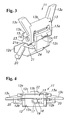
- Fig. 3 is a perspective view of an entire clip according to the present invention;
- Fig. 4 is a top view of the clip;
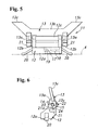
- Fig. 5 is a side view of the clip; and
- Fig. 6 is a front view of the clip.
- FIG. 1 is a perspective view showing an entire body of an automobile to which the present invention is applied.
- a roof R of a car body 1 includes a main roof panel 2 covering a large part of the roof R at the central portion in the horizontal direction, and side roof panels 3 adjacent to window frames at both sides of the main roof panel 2.
- the both roof panels 2, 3 shown by phantom lines in Fig. 2 are integrally connected by overlapping and welding edge portions 2a, 3a of the roof panels 2, 3 extending in the front-to-rear direction.
- a groove 4 with an open upper surface extends in the front-to-rear direction at joining portions of the roof panels 2, 3. Incidentally, a direction in the present specification is expressed relative to the car body for convenience.
- the groove 4 has a U-character shape section, and a shallow step 5 is formed on one side edge (on the side of the side roof panel 3) of the open surface.
- a strip member 6 coated with a synthetic resin abuts against the step 5, and the other side thereof abuts against an upper surface of the main roof panel 2, so that the joining portions of the roof panels 2, 3 are covered with the strip member 6, thereby obtaining a good appearance.
- the strip member 6 includes a core 7 having an approximately C shape cross section with a downward opening and a covering portion 8 formed of a relatively soft synthetic resin for covering an outer surface of the core 7. Sealing portions 8a, 8b are continuously formed at both side edges of the covering portion for elastically contacting the upper surfaces of the panels 2, 3 continued to the open surface of the groove 4, thereby preventing water from entering the groove 4.
- the strip member 6 is attached to the car body with the clip as described below.
- a clip 11 is formed of a hard synthetic resin material. As shown in Figs. 3 to 6, the clip 11 includes a car body side joining portion (a first portion) 12 and a strip side joining portion (a second portion) 13. When shaft portions 14 projecting from both end surfaces of the car body side joining portion 12 in the front and rear directions are fitted in bearing holes 15 formed on the strip side joining portion 13, the car body side joining portion 12 and the strip side joining portion 13 are relatively rotatable by a predetermined angle.
- the car body side joining portion 12 includes a base portion 12a connected to a wide diameter head portion 16 of a T-stud uprightly welded on the bottom surface of the groove 4; stay portions 12b projecting upwardly at both front and rear end surfaces of the base portion 12a for supporting the strip side joining portion 13; and a bridge portion 12c for connecting upper surfaces of the front and rear stay portions 12b facing the side roof panel 3.
- the base portion 12a has an approximately rectangular shape, and a vertically penetrating long hole 17 extends from an intermediate portion of the base portion 12a to the forward end thereof in the front and rear directions.
- An engaging member 18 having a cantilever beam shape is projected from an inner surface of a forward end side of the long hole 17 at an intermediate portion in the vertical direction, so that a free end portion thereof is bent in the vertical direction.
- An inward step portion 19 extending in the peripheral direction is formed at an intermediate portion of an inner peripheral wall in the height direction rearwards from an intermediate portion of the long hole 17 in the front-to-rear direction.
- elastic members 20 extend diagonally downward from upper portions of the respective front and rear end surfaces of the base portion 12a.
- Ratchet lever portions 21 having hook nails 21a at free ends thereof and the shaft portions 14 are vertically disposed side by side on the respective front and rear end surfaces of the stay portions 12b.
- a projection 22 having a triangular cross section is formed on an outer surface at an intermediate portion of the bridge portion 12c in the front and rear directions.
- the strip side joining portion 13 includes shaft receiving holes 15 for receiving therein the shaft portions 14; a pair of front and rear shaft receiving plates 13a provided with ratchet claws 23 for engaging the hook nails 21a of the ratchet lever portions 21 and stopper projections 24; a connecting plate 13b for connecting the front and rear shaft receiving plates 13a; and a pair of angular projections 13c extending diagonally outwards from the respective connecting portions of the front and rear shaft receiving plates 13a and connecting plate 13b.
- the core 7 of the strip member 6 has a flat C-character shape as a whole.
- a deep groove 7a is formed at a side of the core positioned at the center of the roof R, and a shallow groove 7b is formed at the opposite side thereof.
- the angular projections 13c of the strip side joining portion 13 are received in the deep groove 7a.
- An edge at the shallow groove 7b side hooks on a projection 22 of the outer surface of the bridge portion 12c of the car body side joining portion 12, so that the strip member 6 is attached to the clip 11.
- the strip side joining portion 13 is held in a standing state. While the pair of the angular projections 13c is covered with the deep groove 7a of the core 7, the strip side joining portion 13 is rotated in a falling-down direction so that one side sealing portion 8a is pressed against the upper surface of the main roof panel 2. Then, while bending the angular projections 13c as well as the bridge portion 12c of the car body side joining portion 12, the projection 22 on the outer surface of the bridge portion 12c is allowed to get over an edge of the shallow groove 7b of the core 7. The shallow groove 7b side is allowed to engage the projection 22, and the other side sealing portion 8b is allowed to abut against the step 5 of the groove 4. Thus, the completely joined state as shown in Fig. 2 is obtained.
- a distance from the forward end of the angular projection 13c to the outer end of the projection 22 of the bridge portion 12c is set to be larger than an inner width dimension of the core 7 of the strip member 6, when the strip side joining portion 13 is fallen down without any outer force.
- the shaft portion 14 and the shaft receiving hole 15 have a gourd shape narrowed at an intermediate portion. When both of them are held in an upright state, the outlines thereof are overlapped with each other.
- the stopper projection 24 faces the hook nail 21a of the ratchet lever portion 21. Therefore, when there is no outer force, the upright state is held, so that the workability of attaching the strip member 6 to the strip side joining portion 13 is improved.
- the narrowed portion of the shaft receiving hole 15 contacts the swelled portion of the shaft portion 14, thereby causing friction.
- the ratchet claw 23 pushes away the ratchet lever portion 21 to deform, so that the elastic force also acts as the rotational friction.
- the ratchet lever portion 21 restores to the original state from the elastically deformed state by the ratchet claw 23 of the strip side joining portion 13 when the strip side joining portion 13 is rotated.
- the hook nail 21a of the free end engages the ratchet claw 23. At this time, there is no rotational friction by the ratchet lever portion 21, and the operator can easily recognize that the ratchet lever portion 21 reaches the complete position.
- the strip side joining portion of the clip is held in the upright state. Therefore, the attaching ability of the strip member to the clip fixed in advance is greatly improved. Moreover, the bending margin of the clip can be set relatively large. Therefore, the binding strength of the strip member with respect to the clip can be increased greatly.
- the shaft and the shaft receiving hole are formed in the non-circular shape so that the strip side joining portion can be held in the upright state through the contact resistance. Therefore, it is possible to eliminate the wobbling around the rotational center.
- the ratchet mechanism is provided for locking the strip side joining portion with respect to the car body side joining portion, thereby creating the restriction when it stops. Therefore, the operator can easily and positively determine the assembling completion state. Moreover, the holding force can be easily adjusted through setting the height of the claw or the like.
Landscapes
- Engineering & Computer Science (AREA)
- General Engineering & Computer Science (AREA)
- Mechanical Engineering (AREA)
- Connection Of Plates (AREA)
- Vehicle Interior And Exterior Ornaments, Soundproofing, And Insulation (AREA)
Abstract
Description
Fig. 2 is a sectional view showing an essential part taken along line 2-2 in Fig. 1;
Fig. 3 is a perspective view of an entire clip according to the present invention;
Fig. 4 is a top view of the clip;
Fig. 5 is a side view of the clip; and
Fig. 6 is a front view of the clip.
Claims (7)
- A clip (11) for attaching a strip member (6) to a groove (4), comprising:a first portion (12) to be attached to the groove, anda second portion (13) to be attached to the strip member,said clip (11) being characterized in that said second portion (13) is rotatably connected to the first portion (12) around an axis line along the groove, anda holding device (14, 15) is disposed between the first portion and the second portion for holding the second portion in an upright state relative to the first portion.
- A clip (11) for attaching a strip member according to claim 1, wherein said holding device includes a shaft (14) disposed on one of the first and second portions, and a shaft receiving hole (15) disposed on the other of the first and second portions for receiving the shaft, said shaft (14) and shaft receiving hole (15) having a non-circular cross section perpendicular to the axis line so that when the shaft and shaft receiving hole are engaged without force, the second portion is held in the upright state.
- A clip (11) for attaching a strip member according to claim 1 or 2, further comprising an engagement device (21a, 23) with a ratchet function disposed between the first portion and the second portion for fixing the second portion relative to the first portion in an inclined state.
- A clip (11) for attaching a strip member according to claim 3, wherein said engagement device includes a hook (21a) formed on the first portion, and a ratchet tooth (23) formed on the second portion so that when the second portion is rotated relative to the first portion, the ratchet tooth (23) engages the hook (21a) to hold the second portion in the inclined state.
- A clip (11) for attaching a strip member according to claim 4, wherein said second portion further includes a stopper projection (24) engaging the hook (21a) so that the second portion is held in the upright state.
- A clip (11) for attaching a strip member according to any one of claims 1 to 5, wherein said first portion includes an engagement hole (17) for engaging a stud (16) formed on the groove, and an elastic member (20) at a bottom thereof so that when the engagement hole engages the stud, the elastic member (20) abuts against the groove to stably hold the first portion.
- A clip (11) for attaching a strip member according to any one of claims 1 to 6, wherein said first portion includes a first projection (22) at one side thereof, and said second portion includes a second projection (13c) at one side thereof, said first and second projections engaging the strip member for holding the same.
Applications Claiming Priority (2)
| Application Number | Priority Date | Filing Date | Title |
|---|---|---|---|
| JP2002292684 | 2002-10-04 | ||
| JP2002292684A JP2004125122A (en) | 2002-10-04 | 2002-10-04 | Mall mounting clip |
Publications (2)
| Publication Number | Publication Date |
|---|---|
| EP1405766A1 true EP1405766A1 (en) | 2004-04-07 |
| EP1405766B1 EP1405766B1 (en) | 2006-05-24 |
Family
ID=31987224
Family Applications (1)
| Application Number | Title | Priority Date | Filing Date |
|---|---|---|---|
| EP03018700A Expired - Lifetime EP1405766B1 (en) | 2002-10-04 | 2003-08-22 | Clip for attaching strip member |
Country Status (4)
| Country | Link |
|---|---|
| US (1) | US7556449B2 (en) |
| EP (1) | EP1405766B1 (en) |
| JP (1) | JP2004125122A (en) |
| DE (1) | DE60305404T2 (en) |
Families Citing this family (2)
| Publication number | Priority date | Publication date | Assignee | Title |
|---|---|---|---|---|
| US7980613B2 (en) * | 2008-08-07 | 2011-07-19 | Honda Motor Co., Ltd. | Rear garnish clip |
| JP5856027B2 (en) * | 2012-08-09 | 2016-02-09 | 株式会社コスメック | Clamping device |
Citations (5)
| Publication number | Priority date | Publication date | Assignee | Title |
|---|---|---|---|---|
| US3634991A (en) * | 1969-11-13 | 1972-01-18 | Gen Motors Corp | Molding retainer |
| GB2040350A (en) * | 1979-01-19 | 1980-08-28 | Tucker Fasteners Ltd | Securing trim |
| JP2001030852A (en) * | 1999-07-21 | 2001-02-06 | Togo Seisakusho Corp | Roof molding clip |
| FR2800024A1 (en) * | 1999-10-22 | 2001-04-27 | Aries Ind Structure | Decorative trim, for vehicle roof, has lower profile section, designed to anchor to mounting feet and upper profile in two longitudinal sections |
| EP1211115A2 (en) * | 2000-11-29 | 2002-06-05 | Emhart LLC | Clip for fixing strips |
Family Cites Families (12)
| Publication number | Priority date | Publication date | Assignee | Title |
|---|---|---|---|---|
| US4229844A (en) * | 1979-04-30 | 1980-10-28 | Ethyl Corporation | Swimming pool coping |
| US4530195A (en) * | 1980-04-03 | 1985-07-23 | Glass Equipment Development, Inc. | Spacer frame for an insulating glass panel and method of making the same |
| CA1294824C (en) * | 1987-01-21 | 1992-01-28 | Gunter Berdan | Fold-up corner piece for spacer tube assembly |
| US4794663A (en) * | 1987-03-02 | 1989-01-03 | Quickie Manufacturing Company, Inc. | Flexible dust mop |
| US4942271A (en) * | 1988-12-07 | 1990-07-17 | Hubbell Incorporated | Hinged plastic duct for conduit |
| JP2563935Y2 (en) * | 1991-02-14 | 1998-03-04 | 株式会社ニフコ | Mounting fixture |
| US5154531A (en) * | 1991-04-09 | 1992-10-13 | Alumet Mfg., Inc. | Flexible corner connector for insulated glass panel spacer frame |
| DE9406076U1 (en) * | 1994-04-13 | 1994-06-23 | Emhart Inc., Newark, Del. | Fastening device for rod-shaped objects |
| JP3075707B2 (en) * | 1997-12-24 | 2000-08-14 | 日本圧着端子製造株式会社 | Printed wiring board connector |
| US6053458A (en) * | 1998-01-08 | 2000-04-25 | Illinois Tool Works Inc. | Swivel hinge for a clip |
| US6368125B1 (en) * | 1999-05-18 | 2002-04-09 | Tyco Electronics Corporation | Connector with lever |
| US6736655B2 (en) * | 2002-04-17 | 2004-05-18 | Tyco Electronics Corporation | Rack and pinion electrical connector with offset gear teeth |
-
2002
- 2002-10-04 JP JP2002292684A patent/JP2004125122A/en active Pending
-
2003
- 2003-08-21 US US10/644,973 patent/US7556449B2/en not_active Expired - Fee Related
- 2003-08-22 DE DE60305404T patent/DE60305404T2/en not_active Expired - Lifetime
- 2003-08-22 EP EP03018700A patent/EP1405766B1/en not_active Expired - Lifetime
Patent Citations (5)
| Publication number | Priority date | Publication date | Assignee | Title |
|---|---|---|---|---|
| US3634991A (en) * | 1969-11-13 | 1972-01-18 | Gen Motors Corp | Molding retainer |
| GB2040350A (en) * | 1979-01-19 | 1980-08-28 | Tucker Fasteners Ltd | Securing trim |
| JP2001030852A (en) * | 1999-07-21 | 2001-02-06 | Togo Seisakusho Corp | Roof molding clip |
| FR2800024A1 (en) * | 1999-10-22 | 2001-04-27 | Aries Ind Structure | Decorative trim, for vehicle roof, has lower profile section, designed to anchor to mounting feet and upper profile in two longitudinal sections |
| EP1211115A2 (en) * | 2000-11-29 | 2002-06-05 | Emhart LLC | Clip for fixing strips |
Non-Patent Citations (1)
| Title |
|---|
| PATENT ABSTRACTS OF JAPAN vol. 2000, no. 19 5 June 2001 (2001-06-05) * |
Also Published As
| Publication number | Publication date |
|---|---|
| DE60305404T2 (en) | 2006-11-23 |
| DE60305404D1 (en) | 2006-06-29 |
| JP2004125122A (en) | 2004-04-22 |
| EP1405766B1 (en) | 2006-05-24 |
| US7556449B2 (en) | 2009-07-07 |
| US20040067100A1 (en) | 2004-04-08 |
Similar Documents
| Publication | Publication Date | Title |
|---|---|---|
| US20020101096A1 (en) | Clip for attaching cover member and structure for attaching the cover member | |
| JPS5950529B2 (en) | Vehicle window molding installation device | |
| EP1405766B1 (en) | Clip for attaching strip member | |
| JPH1086765A (en) | Mall clips | |
| JP3297629B2 (en) | Positioning structure of windshield panel for automobile | |
| JP4017718B2 (en) | Clip for roof molding | |
| JPH0618848Y2 (en) | Automotive roof molding installation device | |
| JPH0310404Y2 (en) | ||
| JP3416003B2 (en) | Pantograph jack holding device | |
| JPH0214485Y2 (en) | ||
| JP3352991B2 (en) | Roof panel connection structure and roof panel fastener | |
| JPH04121510U (en) | Molding mounting clip | |
| JPH0114489Y2 (en) | ||
| JP2509803Y2 (en) | Clip for T-stud | |
| JP3879710B2 (en) | Wall panel mounting structure | |
| JP2540720B2 (en) | A suspension for a thatched roof and a roof structure using this suspension | |
| JPH01160727A (en) | Cover of sliding movablle roof for automobile | |
| JP2543071Y2 (en) | Eave gutter support device | |
| JPH0738529Y2 (en) | Backing plate | |
| JPH0738527Y2 (en) | Roof board joining material | |
| JPH0738018Y2 (en) | Roof molding mounting structure | |
| JPS6116168Y2 (en) | ||
| JPS621443Y2 (en) | ||
| JPS6128822Y2 (en) | ||
| JP2548317Y2 (en) | Eaves back ceiling panel |
Legal Events
| Date | Code | Title | Description |
|---|---|---|---|
| PUAI | Public reference made under article 153(3) epc to a published international application that has entered the european phase |
Free format text: ORIGINAL CODE: 0009012 |
|
| AK | Designated contracting states |
Kind code of ref document: A1 Designated state(s): AT BE BG CH CY CZ DE DK EE ES FI FR GB GR HU IE IT LI LU MC NL PT RO SE SI SK TR |
|
| AX | Request for extension of the european patent |
Extension state: AL LT LV MK |
|
| 17P | Request for examination filed |
Effective date: 20040227 |
|
| 17Q | First examination report despatched |
Effective date: 20040727 |
|
| AKX | Designation fees paid |
Designated state(s): DE FR GB |
|
| GRAP | Despatch of communication of intention to grant a patent |
Free format text: ORIGINAL CODE: EPIDOSNIGR1 |
|
| GRAS | Grant fee paid |
Free format text: ORIGINAL CODE: EPIDOSNIGR3 |
|
| GRAA | (expected) grant |
Free format text: ORIGINAL CODE: 0009210 |
|
| AK | Designated contracting states |
Kind code of ref document: B1 Designated state(s): DE FR GB |
|
| REG | Reference to a national code |
Ref country code: GB Ref legal event code: FG4D |
|
| REF | Corresponds to: |
Ref document number: 60305404 Country of ref document: DE Date of ref document: 20060629 Kind code of ref document: P |
|
| ET | Fr: translation filed | ||
| PLBE | No opposition filed within time limit |
Free format text: ORIGINAL CODE: 0009261 |
|
| STAA | Information on the status of an ep patent application or granted ep patent |
Free format text: STATUS: NO OPPOSITION FILED WITHIN TIME LIMIT |
|
| 26N | No opposition filed |
Effective date: 20070227 |
|
| PGFP | Annual fee paid to national office [announced via postgrant information from national office to epo] |
Ref country code: FR Payment date: 20080818 Year of fee payment: 6 |
|
| REG | Reference to a national code |
Ref country code: FR Ref legal event code: ST Effective date: 20100430 |
|
| PG25 | Lapsed in a contracting state [announced via postgrant information from national office to epo] |
Ref country code: FR Free format text: LAPSE BECAUSE OF NON-PAYMENT OF DUE FEES Effective date: 20090831 |
|
| PGFP | Annual fee paid to national office [announced via postgrant information from national office to epo] |
Ref country code: DE Payment date: 20130814 Year of fee payment: 11 |
|
| PGFP | Annual fee paid to national office [announced via postgrant information from national office to epo] |
Ref country code: GB Payment date: 20130821 Year of fee payment: 11 |
|
| REG | Reference to a national code |
Ref country code: DE Ref legal event code: R119 Ref document number: 60305404 Country of ref document: DE |
|
| GBPC | Gb: european patent ceased through non-payment of renewal fee |
Effective date: 20140822 |
|
| REG | Reference to a national code |
Ref country code: DE Ref legal event code: R119 Ref document number: 60305404 Country of ref document: DE Effective date: 20150303 |
|
| PG25 | Lapsed in a contracting state [announced via postgrant information from national office to epo] |
Ref country code: GB Free format text: LAPSE BECAUSE OF NON-PAYMENT OF DUE FEES Effective date: 20140822 Ref country code: DE Free format text: LAPSE BECAUSE OF NON-PAYMENT OF DUE FEES Effective date: 20150303 |