EP1405729A1 - Printer - Google Patents
Printer Download PDFInfo
- Publication number
- EP1405729A1 EP1405729A1 EP20030256194 EP03256194A EP1405729A1 EP 1405729 A1 EP1405729 A1 EP 1405729A1 EP 20030256194 EP20030256194 EP 20030256194 EP 03256194 A EP03256194 A EP 03256194A EP 1405729 A1 EP1405729 A1 EP 1405729A1
- Authority
- EP
- European Patent Office
- Prior art keywords
- paper
- sheet
- printing
- support
- printer
- Prior art date
- Legal status (The legal status is an assumption and is not a legal conclusion. Google has not performed a legal analysis and makes no representation as to the accuracy of the status listed.)
- Withdrawn
Links
Images





Classifications
-
- B—PERFORMING OPERATIONS; TRANSPORTING
- B41—PRINTING; LINING MACHINES; TYPEWRITERS; STAMPS
- B41J—TYPEWRITERS; SELECTIVE PRINTING MECHANISMS, i.e. MECHANISMS PRINTING OTHERWISE THAN FROM A FORME; CORRECTION OF TYPOGRAPHICAL ERRORS
- B41J11/00—Devices or arrangements of selective printing mechanisms, e.g. ink-jet printers or thermal printers, for supporting or handling copy material in sheet or web form
- B41J11/0065—Means for printing without leaving a margin on at least one edge of the copy material, e.g. edge-to-edge printing
-
- B—PERFORMING OPERATIONS; TRANSPORTING
- B41—PRINTING; LINING MACHINES; TYPEWRITERS; STAMPS
- B41J—TYPEWRITERS; SELECTIVE PRINTING MECHANISMS, i.e. MECHANISMS PRINTING OTHERWISE THAN FROM A FORME; CORRECTION OF TYPOGRAPHICAL ERRORS
- B41J11/00—Devices or arrangements of selective printing mechanisms, e.g. ink-jet printers or thermal printers, for supporting or handling copy material in sheet or web form
- B41J11/02—Platens
- B41J11/06—Flat page-size platens or smaller flat platens having a greater size than line-size platens
Definitions
- the present invention relates to a printer comprising an scanning ink head having a plurality of nozzles, an ink collector extending parallel to and under the scanning path of the ink head and sheet support members for supporting a sheet being printed on over the ink collector.
- FIG. 1 is a diagram of a conventional printer.
- a sheet of paper 11 is fed between a paper feed roller 12 and a pressure roller 14 in a paper feed direction.
- a head 15 ink from an ink cartridge (not shown), installed in the head 15, is expelled onto the paper 11 through nozzles (not shown).
- the head 15 performs a reciprocating motion in a scan direction, i.e. a direction perpendicular to the paper feed direction, while expelling ink.
- the paper 11 is discharged by a discharge roller 16 and a star wheel 18.
- Figure 2 is a diagram showing a sheet of paper on which printing by the conventional printer shown in Figure 1 has been completed.
- the conventional printer is designed such that printing is not performed in the margins 11-A, 11-B, 11-C, and 11-D even if the user sets the printing margin to 0.
- US-A-20020070991 discloses a printer which can print in the margins of a sheet without contaminating the printer's rollers and a shingling method.
- FIG 3 is a schematic side view of the printer disclosed in US-A-20020070991.
- a sheet of paper P passes between upstream feed rollers 25a, 25b and transported in a paper feed direction.
- the front margin Pf of the sheet P passes over a front slot 26f and a platen 26 and reaches a rear slot 26r.
- ink Ip is expelled from the head 28 by nozzles #1 through #8, and to effect printing. Since printing starts before the front margin Pf of the sheet P reaches the first nozzle #1, printing can be performed starting from the front margin Pf without a printing margin. Ink drops, which miss the sheet P are absorbed by absorption members 27f, 27r.
- the front to back depth of print heads has been increased to increase the speed of printing.
- the depth of the platen 26 In order to increase the depth of the ink head, the depth of the platen 26 must also be increased.
- the distance between the front slot 26f and the rear slot 26r is increased, so it is difficult to guide the sheet P through the printing section without it becoming skewed.
- the rear edge of a sheet must be located above a slot when being printed, which limits the feeding during printing in a margin and a high degree of mechanical precision is required.
- nozzle variation decreases as compared to normal shingling and thus the quality of the printed image is degraded.
- a printer according to the present invention is characterised by the sheet support members extending partially across the ink collector from the sheet feeding and sheet discharging sides thereof, the support members on the sheet feeding side not being aligned in the sheet feeding direction with support members on the sheet discharge side.
- the support members on the sheet feeding side are interdigitated with support members on the sheet discharging side.
- a controller for controlling the ink head is preferably configured to mask nozzle control signals according to the position of a sheet being printed on with respect to said ink collector.
- the controller is configured to mask nozzle control signals with first and second complementary masks, the first mask being used when a leading or trailing margin of a sheet is lying over the support members on the sheet feeding side and disabling nozzles when substantially aligned with the support members on the sheet feeding side, and the second mask being used when a leading or trailing margin of a sheet is lying over the support members on the sheet discharging side and disabling nozzles when substantially aligned with the support members on the sheet discharging side.
- the controller applies said masks respectively to a sheet feeding side nozzle group and a sheet discharging side nozzle group.
- the first mask enables nozzles when substantially aligned with the support members on the sheet discharging side and the second mask enabling nozzles when substantially aligned with the support members on the sheet feeding side.
- the masks comprise blending patterns of nozzle enabling elements and nozzle disabling elements to blend the periods when nozzles are disabled because of an underlying substantially aligned support member into the period when nozzles are enabled because of an non-underlying substantially aligned support member.
- a printer includes a feed roller 58 and a pinch roller 59 which are used to feed a sheet P, an ink head 51 which performs printing by ejecting ink droplets while moving in a scan direction perpendicular to the paper feed direction, first and second sets of support ribs 53a, 53b which support a sheet P and assist printing, a platen 52, from which the support ribs 53a, 53b project, and a discharge roller 56 and a star wheel 57 which are used to discharge the sheet P.
- the pinch roller 59 presses the sheet P against the feed roller 58.
- the first set of support rib 53a supports sheets on the paper feed side and the second set of support ribs 53b supports sheets on the paper discharge side.
- the ink head 51 includes a nozzle unit 62 with a depth "d" in the paper feed direction.
- the nozzle unit 62 ejects ink droplets onto the sheet P when the ink head 51 moves in the scan direction.
- An ink collector 50 is located under the paper and has a breadth corresponding to the depth "d" of the nozzle unit 62. However, the breadth of the ink collector 50 is not restricted to the depth "d" of the nozzle unit 62 and may be broader than the depth "d” of the nozzle unit 62.
- the ink collector 50 includes a single space or a plurality of spaces, which are parallel with the nozzle unit 62 in the scan direction.
- the ink collector 50 comprises a trough having a floor 50a and walls 50b. In the printer shown in Figures 4A and 4B, the trough is formed integrally with the platen 52. Felt 54 is placed in the trough to absorb ink droplets that miss the sheet.
- the first and second support sets ribs 53a, 53b are interdigitated in an upper portion of the trough forming the ink collector 50.
- Each support rib 53a of the first set extends from the platen 52 on the paper feed side in the paper feed direction
- each support rib 53b of the second set extends from the platen 52 at a paper discharge side in the opposite direction to the paper feed direction.
- the support ribs 53a, 53b of the first and second sets may have the same length, and ends of the first and second support ribs 53a and 53b be aligned with each other in the scan direction.
- the distal ends of the support ribs 53a of the first set may overlap the distal ends of the support ribs 53b of the second set in the feed direction in order to support the sheet P more effectively or the distal ends of the support ribs 53a, 53b may not be aligned or overlap and leave a gap fully across the length of the trough.
- Figure 4A shows the distal end of a support rib 53a of the first set extending in the paper feed direction and overlapping the distal end of a support rib 53b of the second set.
- Figure 4B show the distal end of a support rib 53b of the second set extending in the opposite direction to the paper feed direction and overlapping the distal end of the a support rib 53a of the first set.
- a plurality of first and second support ribs 53a, 53b are arranged alternately in the scan direction such that the distal end of each support rib 53a of the first set is aligned with or overlaps the distal ends of adjacent support ribs 53b of the second set in the scan direction, thereby preventing the sheet P from being jammed.
- the support ribs 53a and 53b are narrow to maximize the ink collecting space in the trough.
- the ink collector 50 follows a single uninterrupted meandering path across the platen 52 in the scan direction.
- the support ribs 53a of the first set and the support ribs 53b of the second set are interdigitated and segment the trough forming the ink collector 50 without actually isolating the segments from each other.
- the support ribs 53a of the first set extend from the platen 52 on the feeding side and the support ribs 53b of the second set extends from the platen 52 on the discharge side.
- the felt 54 has notches to accommodate the support ribs 53a, 53b.
- the sheet P is transported by the feed roller 58 and moves onto the support ribs 53a of the first set and front margin printing then starts with ink droplets being ejected by the nozzle unit 62 (see Figure 4A).
- Shingling modes providing front and rear margin printing are implemented in the printer by applying data, which is generated by masking data corresponding to the positions of the support ribs 53a, 53b, to the ink head 51. These shingling modes can be varied from printer to printer according to the support rib arrangement used.
- a first alternative ink collector 70 includes a plurality of wells separated by barriers 71.
- Support ribs 73a, 73b extend upwards from the barriers 71 to the same height.
- the support ribs 73a, 73b are divided into two sets.
- the support ribs 73a of the first set are on the paper feed sides of the barriers 71 from which they project.
- the support ribs 73b of the second set alternate with those of the first set and extend from the paper discharge side of the barriers 71 from which they project.
- the distal ends support ribs 73a, 73b of the first and second sets are aligned or overlap to prevent paper jams or the distal ends of the support ribs 73a, 73b may not be aligned or overlap and leave a gap fully across the length of the trough.
- An ink absorbing member such as a felt pad, can be further provided within each well of the ink collector 70 in order to collect ink more effectively.
- the support ribs 73b of the second set are rounded or slope gently downwards by a distance "h" at their distal ends, as shown in Figure 7A, to prevent paper jams.
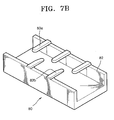
- a second alternative ink collector 80 includes a plurality of support fingers 83a, 83b in two interdigitated sets projecting respectively from the tops of the paper feed and paper discharge sides of an uninterrupted trough 82 which forms in trap of the ink collector 80.
- the distal ends of the support fingers 83a, 83b of the first and second sets are aligned or overlap or the distal ends of the support finger 83a, 83b may not be aligned or overlap and leave a gap fully across the length of the trough.
- the tops of the distal ends of the support fingers 83a of the first set are rounded or chamfered to prevent paper jams.
- the present invention provides a shingling method providing margin printing along with the above-described printer.
- a conventional shingling method consecutive printing scans are made to overlap with each other so that a high-resolution image can be printed.
- the printing is effected differently at different scan positions.
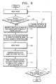
- a sheet is initially moved in the paper feed direction by a paper feed motor in operation 101. If it is determined that a front or rear margin of the sheet is located under a nozzle unit in operation 103, first data is generated by masking data corresponding to the positions of the support ribs 53a on the paper feed side in operation 105. However, if it is determined that neither the front nor the rear margin of the sheet is located under the nozzle unit, printing is performed in a conventional shingling mode in operation 104. After completing printing in the normal shingling mode, if it is determined that more content remains to be printed in operation 115, the shingling algorithm goes to operation 101.
- the presence of the front or rear margin of the sheet under the nozzle unit can be determined using a sensor.
- a sensor When the front or rear margin of the sheet is located under the nozzle unit, as shown in Figure 4A, that margin rests initially on the support ribs at the paper feed side.
- the first data is applied to the nozzle unit and thus printed in the front or rear margin of the sheet, which is positioned on the support ribs, in operation 107.
- the paper is moved in operation 109. It is possible that the paper feed motor is rotated to move the paper by 1/2 of the entire depth "d" of the nozzle unit in one go. In other words, one half of the nozzle unit scans across the support ribs 53a on the paper feed side, and the other half scans across the support ribs 53b on the paper discharge side.
- second data complementing the first data is generated in operation 111.
- the second data is applied to the nozzle unit 62 and is printed in the front or rear margin of the paper between the support ribs on the paper discharge side in operation 113. Since the first data has a complementary relationship with the second data, when both the first and second data have been printed, edge printing is completed.
- a shingling method providing edge printing according to the present invention can accomplish a high resolution printing by performing shingling in the paper feed direction, like the conventional shingling method, along with shingling in the scan direction.
- a first set of sections 62a of the nozzle unit 62 eject ink droplets so that printing is performed in the front edge margin of the sheet P.
- the print control data is masked, producing the first data, to ensure that the nozzles are not activated when over the feed side support ribs 53a. Accordingly, in a first stage in the shingling method providing front margin printing, data is printed only on parts P-A of the sheet P which are positioned between the feed side support ribs 53a.
- the second data is applied to the second section 62b of the nozzle unit 62 and data is simultaneously applied to the first section 62a of the nozzle unit 62 such that printing is performed on the sheet P in normal shingling mode.
- the front edge printing is completed.
- the first and second data have a complementary relationship and are printed at complementary positions in the scan direction in shingling mode for front margin printing.
- the shingling method providing front margin printing according to this embodiment can be applied to any structure, in which support ribs are formed as shown in Figures 4A through 7B, or in which support ribs at a paper feed side alternate with support ribs at a paper discharge side so as to effectively support the sheet P and an ink collector is formed to collect ink through spaces between the support ribs.
- Figure 9C shows a third stage, in which printing is performed in the normal shingling mode, after the shingling method providing front margin printing is completed in the first and second stages and then the sheet P is moved.
- the first and second sections 62a, 62b of the nozzle unit 62 eject ink droplets in the normal shingling mode so that printing for an intermediate portion P-C of the sheet P is performed..
- rear margin printing is performed in the normal shingling mode by ejecting ink droplets using the first and second sections 62a, 62b of the nozzle unit 62 onto area P-E.
- Figure 10B when the margin edge of the sheet P is moved under the nozzle unit 62, printing is performed on the sheet P except for parts P-F of the sheet P positioned over the feed side support ribs 53a.
- first data which is generated by masking data corresponding to the positions of the first support ribs 53a among data to be printed on the rear margin of the sheet P, is applied to the first section 62a of the nozzle unit 62.
- the sheet P is moved by half of the depth of the nozzle unit 62.
- second data complementing the first data is applied to the second section 62b of the nozzle unit 62, and thus printed on the rear part P-G of the rear margin of the sheet P which is positioned on the discharge side support ribs 53b in a second stage.
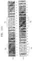
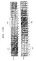
- Figures 11A through 11C are diagrams showing examples of masks used in a shingling method providing edge printing according to embodiments of the present invention. Each of the example masks is represented using hexadecimal numbers.
- a borderline may appear between the printing areas P-A and P-B in Figure 9B and between the printing areas P-F and P-G in Figure 10C, thereby degrading picture quality.
- a shingling method providing edge printing is performed, printing in the printing areas P-A and P-B or P-F and P-G is not simultaneously performed, and thus ink ejected on the sheet P become dry at different times. As a result, a borderline appears between these printing areas.
- the present invention provides a mask, which filters image data for edge printing.
- Masks are paired and the masks in a pair are complementary. Accordingly, a complete image can be formed only after both masks of a mask pair have been used. During margin printing, one mask of the mask pair is repeatedly used for some scans and the other of the mask pair is repeatedly used for the other scans, so that a complete image is formed. In each mask, a 100% printing column 1 to print image data in the scan direction of a nozzle unit and a 0% printing column 0 to not print image data at all are repeated. Data corresponding to the positions of support ribs is filtered by continuously repeating the 0% printing columns 0 so that the support ribs are prevented from being contaminated.
- the portions of the first mask 91a corresponding to feed side support ribs 53a comprise runs 74a of columns containing 0s and the portions of the first mask 91a corresponding to a discharge side support ribs 53a comprise runs 76a of columns containing 1s.
- the intervening portions contain patterns of columns of 1s and 0s so that the runs 74a of columns containing 0s, corresponding to feed side support ribs 53a, blend into the runs 74b of columns containing 1s, corresponding to discharge side support ribs 53b.
- the second mask 91b is the complement of the first mask with runs 76b of 1s aligned with the runs 74a of 0s of the first mask 91a and with runs 74b of 0s aligned with the runs 76a of 0s of the first mask 91a.
- the blending patterns are similarly complementary to prevent the formation of borderlines.
- a first mask 81a and a second mask 81b have complementary data arrays containing runs 86a, 86b and runs 84a, 84b of 0s as in Figure 11A. However the blending pattern is different.
- a first mask 71a and a second mask 71b have complementary data arrays containing runs 96a, 96b and runs 94a, 94b of 0s as in Figure 11A. However the blending pattern is different again.
- the present invention uses masks, as shown in Figures 11A, 11B, or 11C, in order to remove a borderline between a printing area in which printing is performed on paper except for a part corresponding to support ribs, and a printing area in which printing is performed on the part of the paper corresponding to the support ribs. Consequently, degradation of picture quality can be prevented.
- an ink collector has a structure suitable to shingling providing edge printing.
- support ribs extending from one side of an ink collector in a paper feed direction are interlaced with support ribs extending from the other side thereof in an opposite direction to the paper feed direction, so that a shingling algorithm providing edge printing can be variously applied without contaminating the support ribs and the front and rear edge portions of paper can be effectively supported.
- various modifications can be made to support ribs.
- the present invention provides a shingling method providing edge printing so that printing can be performed on the front and rear edge portions of paper without leaving a margin and without contaminating support ribs.
- the present invention also uses filtering masks to gradually print data in an area between support ribs so that degradation of picture quality can be prevented.
- support ribs of an ink collector are alternately arranged with each other, thereby effectively supporting the front and rear edge portion of paper and efficiently collecting ink digressing from the paper.
- printing can be performed on the front and rear edge portions of paper at a high resolution without leaving a margin and without contaminating support ribs.
Landscapes
- Ink Jet (AREA)
Abstract
Description
- The present invention relates to a printer comprising an scanning ink head having a plurality of nozzles, an ink collector extending parallel to and under the scanning path of the ink head and sheet support members for supporting a sheet being printed on over the ink collector.
- Figure 1 is a diagram of a conventional printer. Referring to Figure 1, in the conventional printer, a sheet of
paper 11 is fed between apaper feed roller 12 and apressure roller 14 in a paper feed direction. When thepaper 11 is located under ahead 15, ink from an ink cartridge (not shown), installed in thehead 15, is expelled onto thepaper 11 through nozzles (not shown). Thehead 15 performs a reciprocating motion in a scan direction, i.e. a direction perpendicular to the paper feed direction, while expelling ink. After completion of printing, thepaper 11 is discharged by adischarge roller 16 and astar wheel 18. - Figure 2 is a diagram showing a sheet of paper on which printing by the conventional printer shown in Figure 1 has been completed. As shown in Figure 2, when a user sets the printer to perform printing over the whole of the sheet of
paper 11, printing is actually performed only within a printable area 11-E and not in the margins 11-A, 11-B, 11-C, and 11-D of the sheet. The conventional printer is designed such that printing is not performed in the margins 11-A, 11-B, 11-C, and 11-D even if the user sets the printing margin to 0. - In order to overcome this problem, US-A-20020070991 discloses a printer which can print in the margins of a sheet without contaminating the printer's rollers and a shingling method.
- Figure 3 is a schematic side view of the printer disclosed in US-A-20020070991. Referring to Figure 3, a sheet of paper P passes between
upstream feed rollers front slot 26f and aplaten 26 and reaches arear slot 26r. At this time, ink Ip is expelled from thehead 28 bynozzles # 1 through #8, and to effect printing. Since printing starts before the front margin Pf of the sheet P reaches thefirst nozzle # 1, printing can be performed starting from the front margin Pf without a printing margin. Ink drops, which miss the sheet P are absorbed byabsorption members discharge roller front slot 26f and theplaten 26 toward therear slot 26r. Printing for the rear margin Pr of the sheet P is performed in the same manner as printing for the front margin Pf of the sheet P. - Recently, the front to back depth of print heads has been increased to increase the speed of printing. In order to increase the depth of the ink head, the depth of the
platen 26 must also be increased. When increasing the depth of theplaten 26, the distance between thefront slot 26f and therear slot 26r is increased, so it is difficult to guide the sheet P through the printing section without it becoming skewed. - Different complex shingling processes are used for printing on the front, middle, and rear portions of a sheet. Moreover, in order to perform normal printing on the middle portion of paper, only some of the nozzles are used, which means that the printing speed is not optimal.
- In addition, the rear edge of a sheet must be located above a slot when being printed, which limits the feeding during printing in a margin and a high degree of mechanical precision is required. Moreover, when performing shingling without feeding paper, nozzle variation decreases as compared to normal shingling and thus the quality of the printed image is degraded.
- A printer according to the present invention is characterised by the sheet support members extending partially across the ink collector from the sheet feeding and sheet discharging sides thereof, the support members on the sheet feeding side not being aligned in the sheet feeding direction with support members on the sheet discharge side.
- Preferably, the support members on the sheet feeding side are interdigitated with support members on the sheet discharging side.
- A controller for controlling the ink head is preferably configured to mask nozzle control signals according to the position of a sheet being printed on with respect to said ink collector.
- Preferably, the controller is configured to mask nozzle control signals with first and second complementary masks, the first mask being used when a leading or trailing margin of a sheet is lying over the support members on the sheet feeding side and disabling nozzles when substantially aligned with the support members on the sheet feeding side, and the second mask being used when a leading or trailing margin of a sheet is lying over the support members on the sheet discharging side and disabling nozzles when substantially aligned with the support members on the sheet discharging side.
- Preferably, the controller applies said masks respectively to a sheet feeding side nozzle group and a sheet discharging side nozzle group.
- Preferably, the first mask enables nozzles when substantially aligned with the support members on the sheet discharging side and the second mask enabling nozzles when substantially aligned with the support members on the sheet feeding side.
- Preferably, the masks comprise blending patterns of nozzle enabling elements and nozzle disabling elements to blend the periods when nozzles are disabled because of an underlying substantially aligned support member into the period when nozzles are enabled because of an non-underlying substantially aligned support member.
- Further preferred and optional features are set forth in
claims 8 to 31 appended hereto. - Embodiments of the present invention will now be described, by way of example, with reference to Figures 4A to 11C of the accompanying drawings, in which:
- Figure 1 is a schematic diagram of a conventional printer;
- Figure 2 is a diagram showing the printable area of a sheet of paper when using a conventional printer;
- Figure 3 is a schematic side view of a conventional printer;
- Figures 4A and 4B are schematic diagrams of a printer according to the present invention, respectively;
- Figure 5 is a perspective view of part of the printer of Figures 4A and 4B;
- Figure 6 is a diagram a sheet of paper being fed into the printer of Figures 4A and 4B;
- Figure 7A is a perspective view of a first alternative ink collector structure of the printer of Figures 4A and 4B;
- Figure 7B is a perspective view of a second alternative ink collector structure;
- Figure 8 is a flowchart of a shingling method providing edge printing according to the present invention;
- Figures 9A to 9C are diagrams showing the stages of a shingling method providing front margin printing according to the present invention;
- Figures 10A through 10C are diagrams showing the stages in a shingling method providing rear margin printing according to the present invention; and
- Figures 11A through 11C are diagrams showing examples of masks used in shingling according to the present invention.
-
- Referring to Figures 4A and 4B, a printer includes a
feed roller 58 and apinch roller 59 which are used to feed a sheet P, anink head 51 which performs printing by ejecting ink droplets while moving in a scan direction perpendicular to the paper feed direction, first and second sets ofsupport ribs platen 52, from which the support ribs 53a, 53b project, and adischarge roller 56 and astar wheel 57 which are used to discharge the sheet P. Thepinch roller 59 presses the sheet P against thefeed roller 58. The first set ofsupport rib 53a supports sheets on the paper feed side and the second set ofsupport ribs 53b supports sheets on the paper discharge side. - The
ink head 51 includes anozzle unit 62 with a depth "d" in the paper feed direction. Thenozzle unit 62 ejects ink droplets onto the sheet P when theink head 51 moves in the scan direction. Anink collector 50 is located under the paper and has a breadth corresponding to the depth "d" of thenozzle unit 62. However, the breadth of theink collector 50 is not restricted to the depth "d" of thenozzle unit 62 and may be broader than the depth "d" of thenozzle unit 62. - The
ink collector 50 includes a single space or a plurality of spaces, which are parallel with thenozzle unit 62 in the scan direction. Theink collector 50 comprises a trough having afloor 50a andwalls 50b. In the printer shown in Figures 4A and 4B, the trough is formed integrally with theplaten 52.Felt 54 is placed in the trough to absorb ink droplets that miss the sheet. - The first and second
support sets ribs ink collector 50. Each support rib 53a of the first set extends from theplaten 52 on the paper feed side in the paper feed direction, and eachsupport rib 53b of the second set extends from theplaten 52 at a paper discharge side in the opposite direction to the paper feed direction. The support ribs 53a, 53b of the first and second sets may have the same length, and ends of the first andsecond support ribs support ribs 53a of the first set may overlap the distal ends of thesupport ribs 53b of the second set in the feed direction in order to support the sheet P more effectively or the distal ends of thesupport ribs support rib 53a of the first set extending in the paper feed direction and overlapping the distal end of asupport rib 53b of the second set. Figure 4B show the distal end of asupport rib 53b of the second set extending in the opposite direction to the paper feed direction and overlapping the distal end of the asupport rib 53a of the first set. - Unlike in the conventional technology, in the above embodiment of the present invention, a plurality of first and
second support ribs support rib 53a of the first set is aligned with or overlaps the distal ends ofadjacent support ribs 53b of the second set in the scan direction, thereby preventing the sheet P from being jammed. In addition, thesupport ribs - Referring to Figure 5, the
ink collector 50 follows a single uninterrupted meandering path across theplaten 52 in the scan direction. Thesupport ribs 53a of the first set and thesupport ribs 53b of the second set are interdigitated and segment the trough forming theink collector 50 without actually isolating the segments from each other. Thesupport ribs 53a of the first set extend from theplaten 52 on the feeding side and thesupport ribs 53b of the second set extends from theplaten 52 on the discharge side. The felt 54 has notches to accommodate thesupport ribs - Referring to Figure 6, the sheet P is transported by the
feed roller 58 and moves onto thesupport ribs 53a of the first set and front margin printing then starts with ink droplets being ejected by the nozzle unit 62 (see Figure 4A). Shingling modes providing front and rear margin printing are implemented in the printer by applying data, which is generated by masking data corresponding to the positions of thesupport ribs ink head 51. These shingling modes can be varied from printer to printer according to the support rib arrangement used. - Referring to Figure 7A, a first
alternative ink collector 70 includes a plurality of wells separated bybarriers 71.Support ribs barriers 71 to the same height. Thesupport ribs support ribs 73a of the first set are on the paper feed sides of thebarriers 71 from which they project. Thesupport ribs 73b of the second set alternate with those of the first set and extend from the paper discharge side of thebarriers 71 from which they project. The distal endssupport ribs support ribs ink collector 70 in order to collect ink more effectively. - The
support ribs 73b of the second set are rounded or slope gently downwards by a distance "h" at their distal ends, as shown in Figure 7A, to prevent paper jams. - Referring to Figure 7B, a second
alternative ink collector 80 includes a plurality ofsupport fingers uninterrupted trough 82 which forms in trap of theink collector 80. The distal ends of thesupport fingers support finger support fingers 83a of the first set are rounded or chamfered to prevent paper jams. - In order to perform printing from a front edge to a rear edge without leaving a margin, the present invention provides a shingling method providing margin printing along with the above-described printer.
- In a conventional shingling method, consecutive printing scans are made to overlap with each other so that a high-resolution image can be printed. However, in a shingling method providing edge printing according to the present invention, the printing is effected differently at different scan positions.
- Referring to Figure 8, during printing, a sheet is initially moved in the paper feed direction by a paper feed motor in
operation 101. If it is determined that a front or rear margin of the sheet is located under a nozzle unit inoperation 103, first data is generated by masking data corresponding to the positions of thesupport ribs 53a on the paper feed side inoperation 105. However, if it is determined that neither the front nor the rear margin of the sheet is located under the nozzle unit, printing is performed in a conventional shingling mode inoperation 104. After completing printing in the normal shingling mode, if it is determined that more content remains to be printed inoperation 115, the shingling algorithm goes tooperation 101. - The presence of the front or rear margin of the sheet under the nozzle unit can be determined using a sensor. When the front or rear margin of the sheet is located under the nozzle unit, as shown in Figure 4A, that margin rests initially on the support ribs at the paper feed side. The first data is applied to the nozzle unit and thus printed in the front or rear margin of the sheet, which is positioned on the support ribs, in
operation 107. Next, the paper is moved inoperation 109. It is possible that the paper feed motor is rotated to move the paper by 1/2 of the entire depth "d" of the nozzle unit in one go. In other words, one half of the nozzle unit scans across thesupport ribs 53a on the paper feed side, and the other half scans across thesupport ribs 53b on the paper discharge side. - When the paper is moved and rests on the
support ribs 53b at the paper discharge side, as shown in Figure 4B, second data complementing the first data is generated inoperation 111. The second data is applied to thenozzle unit 62 and is printed in the front or rear margin of the paper between the support ribs on the paper discharge side inoperation 113. Since the first data has a complementary relationship with the second data, when both the first and second data have been printed, edge printing is completed. Next, it is determined whether more content remains to be printed inoperation 115. If it is determined that more content remains to be printed, the shingling method goes tooperation 101. However, if it is determined that no more content remains to be printed, the shingling method ends. - A shingling method providing edge printing according to the present invention can accomplish a high resolution printing by performing shingling in the paper feed direction, like the conventional shingling method, along with shingling in the scan direction.
- Referring to Figure 9A, when the front margin of a sheet P is moved and located on the
support ribs 53a on the paper feed side and under thenozzle unit 62, a first set ofsections 62a of thenozzle unit 62 eject ink droplets so that printing is performed in the front edge margin of the sheet P. In order to prevent thesupport ribs 53a of the first set being contaminated, the print control data is masked, producing the first data, to ensure that the nozzles are not activated when over the feedside support ribs 53a. Accordingly, in a first stage in the shingling method providing front margin printing, data is printed only on parts P-A of the sheet P which are positioned between the feedside support ribs 53a. - Referring to Figure 9B, after the first stage for front margin printing is completed, as shown in Figure 9A, in a second stage the paper feed motor is rotated to move the sheet by half of the depth of the
nozzle unit 62 so that the sheet P is moved under asecond section 62b of thenozzle unit 62. When the front margin portion of the sheet P rests on the dischargeside support ribs 53b, second data complementing the first data is generated and printed in printing areas P-B. The data corresponding to the positions of dischargeside support ribs 53b is masked to ensure that the nozzles are not activated when over the dischargeside support ribs 53b. The second data is applied to thesecond section 62b of thenozzle unit 62 and data is simultaneously applied to thefirst section 62a of thenozzle unit 62 such that printing is performed on the sheet P in normal shingling mode. When the second stage is completed, the front edge printing is completed. - The first and second data have a complementary relationship and are printed at complementary positions in the scan direction in shingling mode for front margin printing.
- The shingling method providing front margin printing according to this embodiment can be applied to any structure, in which support ribs are formed as shown in Figures 4A through 7B, or in which support ribs at a paper feed side alternate with support ribs at a paper discharge side so as to effectively support the sheet P and an ink collector is formed to collect ink through spaces between the support ribs.
- Figure 9C shows a third stage, in which printing is performed in the normal shingling mode, after the shingling method providing front margin printing is completed in the first and second stages and then the sheet P is moved. The first and
second sections nozzle unit 62 eject ink droplets in the normal shingling mode so that printing for an intermediate portion P-C of the sheet P is performed.. - As shown in Figure 10A, rear margin printing is performed in the normal shingling mode by ejecting ink droplets using the first and
second sections nozzle unit 62 onto area P-E. Thereafter, as shown in Figure 10B, when the margin edge of the sheet P is moved under thenozzle unit 62, printing is performed on the sheet P except for parts P-F of the sheet P positioned over the feedside support ribs 53a. For this operation, first data, which is generated by masking data corresponding to the positions of thefirst support ribs 53a among data to be printed on the rear margin of the sheet P, is applied to thefirst section 62a of thenozzle unit 62. - After completing the first stage, the sheet P is moved by half of the depth of the
nozzle unit 62. Next, as shown in Figure 10C, second data complementing the first data is applied to thesecond section 62b of thenozzle unit 62, and thus printed on the rear part P-G of the rear margin of the sheet P which is positioned on the dischargeside support ribs 53b in a second stage. - Figures 11A through 11C are diagrams showing examples of masks used in a shingling method providing edge printing according to embodiments of the present invention. Each of the example masks is represented using hexadecimal numbers.
- When marginless printing is performed, a borderline may appear between the printing areas P-A and P-B in Figure 9B and between the printing areas P-F and P-G in Figure 10C, thereby degrading picture quality. In other words, when a shingling method providing edge printing is performed, printing in the printing areas P-A and P-B or P-F and P-G is not simultaneously performed, and thus ink ejected on the sheet P become dry at different times. As a result, a borderline appears between these printing areas. In order to overcome this problem, the present invention provides a mask, which filters image data for edge printing.
- Masks are paired and the masks in a pair are complementary. Accordingly, a complete image can be formed only after both masks of a mask pair have been used. During margin printing, one mask of the mask pair is repeatedly used for some scans and the other of the mask pair is repeatedly used for the other scans, so that a complete image is formed. In each mask, a 100
% printing column 1 to print image data in the scan direction of a nozzle unit and a 0% printing column 0 to not print image data at all are repeated. Data corresponding to the positions of support ribs is filtered by continuously repeating the 0% printing columns 0 so that the support ribs are prevented from being contaminated. - Referring to Figure 11A, the portions of the
first mask 91a corresponding to feedside support ribs 53a comprise runs 74a of columns containing 0s and the portions of thefirst mask 91a corresponding to a dischargeside support ribs 53a comprise runs 76a of columns containing 1s. The intervening portions contain patterns of columns of 1s and 0s so that theruns 74a of columns containing 0s, corresponding to feedside support ribs 53a, blend into theruns 74b of columns containing 1s, corresponding to dischargeside support ribs 53b. Thesecond mask 91b is the complement of the first mask withruns 76b of 1s aligned with theruns 74a of 0s of thefirst mask 91a and withruns 74b of 0s aligned with theruns 76a of 0s of thefirst mask 91a. The blending patterns are similarly complementary to prevent the formation of borderlines. - Referring Figure 11B, a
first mask 81a and asecond mask 81b have complementary dataarrays containing runs - Referring Figure 11C, a
first mask 71a and asecond mask 71b have complementary dataarrays containing runs - As described above, the present invention uses masks, as shown in Figures 11A, 11B, or 11C, in order to remove a borderline between a printing area in which printing is performed on paper except for a part corresponding to support ribs, and a printing area in which printing is performed on the part of the paper corresponding to the support ribs. Consequently, degradation of picture quality can be prevented.
- In the printer described above, an ink collector has a structure suitable to shingling providing edge printing. In particular, support ribs extending from one side of an ink collector in a paper feed direction are interlaced with support ribs extending from the other side thereof in an opposite direction to the paper feed direction, so that a shingling algorithm providing edge printing can be variously applied without contaminating the support ribs and the front and rear edge portions of paper can be effectively supported. In a printer according to the present invention, various modifications can be made to support ribs.
- The present invention provides a shingling method providing edge printing so that printing can be performed on the front and rear edge portions of paper without leaving a margin and without contaminating support ribs. The present invention also uses filtering masks to gradually print data in an area between support ribs so that degradation of picture quality can be prevented.
- As described above, in a printer providing edge printing according to the embodiments of the present invention, support ribs of an ink collector are alternately arranged with each other, thereby effectively supporting the front and rear edge portion of paper and efficiently collecting ink digressing from the paper.
- In a shingling method providing edge printing according to the present invention, printing can be performed on the front and rear edge portions of paper at a high resolution without leaving a margin and without contaminating support ribs.
- While this invention has been particularly shown and described with reference to the embodiments thereof, the embodiments should be considered in a descriptive sense only and not for purposes of limitation. Although a few embodiments of the present invention have been shown and described, it will be appreciated by those skilled in the art that changes may be made in these embodiments. For example, the shape of an ink collector or the positions of support ribs can be changed by those skilled in the art.
Claims (31)
- A printer comprising an scanning ink head (51) having a plurality of nozzles (62), an ink collector (50) extending parallel to and under the scanning path of the ink head (51) and sheet support members (53a, 53b; 73a, 73b; 83a, 83b) for supporting a sheet (P) being printed on over the ink collector (50), characterised by the sheet support members (53a, 53b; 73a, 73b; 83a, 83b) extending partially across the ink collector (50) from the sheet feeding and sheet discharging sides thereof, the support members (53a; 73a; 83a) on the sheet feeding side not being aligned in the sheet feeding direction with support members (53b; 73b; 83b) on the sheet discharge side.
- A printer according to claim 1, wherein the support members (53a; 73a; 83a) on the sheet feeding side are interdigitated with support members on the sheet discharging side (53b; 73b; 83b).
- A printer according to claim 1 or 2, including a controller for controlling the ink head (51), the controller being configured to mask nozzle control signals according to the position of a sheet (P) being printed on with respect to said ink collector (51).
- A printer according to claim 3, wherein the controller is configured to mask nozzle control signals with first and second complementary masks (71a, 71 b; 81a, 81b; 91a, 91b), the first mask (71a; 81a; 91a) being used when a leading or trailing margin of a sheet (P) is lying over the support members (53a; 73a; 83a) on the sheet feeding side and disabling nozzles (62a) when substantially aligned with the support members (53a; 73a; 83a) on the sheet feeding side, and the second mask being used when a leading or trailing margin of a sheet (P) is lying over the support members (53b; 73b; 83b) on the sheet discharging side and disabling nozzles (62b) when substantially aligned with the support members (53b; 73b; 83b) on the sheet discharging side.
- A printer according to claim 3 or 4, wherein the controller applies said masks respectively to a sheet feeding side nozzle group (62a) and a sheet discharging side nozzle group (62b).
- A printer according to claim 3, 4 or 5, wherein the first mask enables nozzles (62a) when substantially aligned with the support members (53b; 73b; 83b) on the sheet discharging side and the second mask enabling nozzles when substantially aligned with the support members (53a; 73a; 83a) on the sheet feeding side.
- A printer according to claim 6, wherein the masks comprise blending patterns of nozzle enabling elements and nozzle disabling elements to blend the periods (74a, 74b; 84a, 84b; 94a, 94b) when nozzles (62) are disabled because of an underlying substantially aligned support member (53a, 53b; 73a, 73b, 83a, 83b) into the period (76a, 76b; 86a, 86b; 96a, 96b) when nozzles (62) are enabled because of an non-underlying substantially aligned support member (53a, 53b; 73a, 73b, 83a, 83b).
- A printer comprising:an ink head comprising a nozzle unit to eject ink drops in a shingling mode providing edge printing;an ink collector positioned under paper to correspond to the nozzle unit and collect ink digressing from the paper; anda plurality of support beams extending at an upper portion of the ink collector in a paper feed direction and in an opposite direction to the paper feed direction and alternately arranged with each other in a scan direction.
- The printer of claim 8, wherein the support beams comprise:a first support beam extending from a paper feed side of the ink collector in the paper feed direction; anda second support beam extending from a paper discharge side of the ink collector in the opposite direction to the paper feed direction.
- The printer of claim 9, wherein the first and second support beams extend to have the same length to support the paper.
- The printer of claim 10, wherein an end point of the first support beam and an end point of the second support beam face each other in the scan direction.
- The printer of claim 10, wherein the end portion of the first support beam extends in the paper feed direction to interlace with that of the second support beam.
- The printer of claim 11, wherein one first and second support beams have the same height in a direction toward the ink head, the direction perpendicular to the paper feed direction and the scan direction.
- The printer of claim 12, wherein the first and second support beams have the same height in a direction toward the ink head, the direction perpendicular to the paper feed direction and the scan direction.
- The printer of claim 14, wherein the support beam extends from a barrier, which partitions the ink collector.
- The printer of claim 14, wherein the support beam is a rib segmenting a space of the ink collector without partitioning it.
- The printer of claim 9, wherein the second support beam has a round end portion.
- The printer of claim 9, wherein the second support beam has a slant end portion inclining in the paper feed direction.
- A shingling method to provide edge printing, comprising:feeding paper such that an edge portion of the paper is located under a nozzle unit of an ink head and printing first data on the edge portion of the paper positioned between support beams supporting the paper, the first data being generated by masking data corresponding to positions of the support beams; andmoving the paper in a paper feed direction by a predetermined width and printing second data on the edge portion of the paper positioned between support beams.
- The shingling method of claim 19, wherein the first data and the second data are in a complementary relationship.
- The shingling method of claim 19, wherein in the paper feeding operation, masking is performed using a first mask in which a number of consecutive 0% printing columns, which are alternately distributed with a number of 100% printing columns, gradually changes in inverse proportion to the number of consecutive 100% printing columns in a scan direction perpendicular to the paper feed direction.
- The shingling method of claim 21, wherein in the paper moving operation, the second data is generated by performing masking using a second mask, which is in a complementary relationship with the first mask.
- The shingling method of claim 19, wherein in the paper feeding operation, the support beams extend from a paper feed side in the paper feed direction.
- The shingling method of claim 23, wherein in the paper moving operation, the support beams extend from a paper discharge side in an opposite direction to the paper feed direction and interlace with the support beams extending from the paper feed side.
- The shingling method of claim 23, wherein the support beams are part of an ink collector collecting ink digressing from the paper.
- The shingling method of claim 24, wherein the support beams are part of an ink collector collecting ink digressing from the paper.
- The shingling method of claim 19, wherein in the paper feeding operation, the paper is fed by 1/2 of a width of the nozzle unit in the paper feed direction.
- The shingling method of claim 27, wherein in the paper moving operation, the paper is fed by 1/2 of the width of the nozzle unit in the paper feed direction.
- The shingling method of claim 19, wherein in the paper moving operation, the second data is applied to a nozzle section positioned above the edge portion of the paper, and the other nozzle section operates in a shingling mode providing normal printing.
- The shingling method of claim 19, further comprising moving the paper in the paper feed direction after completing front edge printing in the paper moving operation and performing printing in a normal shingling mode.
- The shingling method of claim 19, further comprising performing printing in a normal shingling mode before the paper feeding operation, wherein printing is performed in a shingling mode providing rear edge printing in the paper feeding operation.
Applications Claiming Priority (4)
| Application Number | Priority Date | Filing Date | Title |
|---|---|---|---|
| KR10-2002-0059773A KR100449741B1 (en) | 2002-10-01 | 2002-10-01 | Printer with structure for edge printing |
| KR2002059773 | 2002-10-01 | ||
| KR10-2002-0062695A KR100438738B1 (en) | 2002-10-15 | 2002-10-15 | Shingling method for printing edge |
| KR2002062695 | 2002-10-15 |
Publications (1)
| Publication Number | Publication Date |
|---|---|
| EP1405729A1 true EP1405729A1 (en) | 2004-04-07 |
Family
ID=31996291
Family Applications (1)
| Application Number | Title | Priority Date | Filing Date |
|---|---|---|---|
| EP20030256194 Withdrawn EP1405729A1 (en) | 2002-10-01 | 2003-10-01 | Printer |
Country Status (2)
| Country | Link |
|---|---|
| US (1) | US20040125164A1 (en) |
| EP (1) | EP1405729A1 (en) |
Families Citing this family (6)
| Publication number | Priority date | Publication date | Assignee | Title |
|---|---|---|---|---|
| US6899421B2 (en) * | 2002-09-05 | 2005-05-31 | Konica Corporation | Platen and inkjet recording apparatus having that platen |
| JP4013909B2 (en) * | 2003-04-10 | 2007-11-28 | セイコーエプソン株式会社 | Liquid ejector |
| US7543899B2 (en) * | 2004-03-25 | 2009-06-09 | Fujifilm Corporation | Inkjet recording apparatus and liquid application method |
| JP4375552B2 (en) * | 2004-07-28 | 2009-12-02 | ブラザー工業株式会社 | Image recording device |
| US7717634B1 (en) * | 2006-01-11 | 2010-05-18 | Lexmark International, Inc. | Trough support ribs |
| EP3659964A1 (en) | 2018-11-28 | 2020-06-03 | Hysilabs, SAS | Catalysed process of production of hydrogen from silylated derivatives as hydrogen carrier compounds |
Citations (3)
| Publication number | Priority date | Publication date | Assignee | Title |
|---|---|---|---|---|
| US20020041303A1 (en) * | 2000-10-10 | 2002-04-11 | Kenji Yoshinaga | Ink jet recording apparatus |
| US20020070991A1 (en) * | 2000-09-27 | 2002-06-13 | Seiko Epson Corporation | Printing up to edges of printing paper without platen soiling |
| US20020089564A1 (en) | 2000-12-27 | 2002-07-11 | Tetsuyo Ohashi | Ink jet recording apparatus and method for performing ink jet recording |
Family Cites Families (4)
| Publication number | Priority date | Publication date | Assignee | Title |
|---|---|---|---|---|
| JPH08169155A (en) * | 1994-10-21 | 1996-07-02 | Seiko Epson Corp | Inkjet printer, recording medium used therefor, recording medium supply source |
| US6158840A (en) * | 1997-03-25 | 2000-12-12 | Seiko Epson Corporation | Ink jet recording apparatus |
| US6239817B1 (en) * | 1998-10-20 | 2001-05-29 | Hewlett-Packard Comapny | Apparatus and method for printing borderless print image |
| US6964466B1 (en) * | 1999-04-06 | 2005-11-15 | Seiko Epson Corporation | Ink-jet recording apparatus and recording method thereof |
-
2003
- 2003-09-29 US US10/671,940 patent/US20040125164A1/en not_active Abandoned
- 2003-10-01 EP EP20030256194 patent/EP1405729A1/en not_active Withdrawn
Patent Citations (3)
| Publication number | Priority date | Publication date | Assignee | Title |
|---|---|---|---|---|
| US20020070991A1 (en) * | 2000-09-27 | 2002-06-13 | Seiko Epson Corporation | Printing up to edges of printing paper without platen soiling |
| US20020041303A1 (en) * | 2000-10-10 | 2002-04-11 | Kenji Yoshinaga | Ink jet recording apparatus |
| US20020089564A1 (en) | 2000-12-27 | 2002-07-11 | Tetsuyo Ohashi | Ink jet recording apparatus and method for performing ink jet recording |
Also Published As
| Publication number | Publication date |
|---|---|
| US20040125164A1 (en) | 2004-07-01 |
Similar Documents
| Publication | Publication Date | Title |
|---|---|---|
| EP1555134B1 (en) | Print media edge printing | |
| EP1193072B1 (en) | Printing up to edges of printing paper without platen soiling | |
| EP0861730B1 (en) | Method of manufacturing a printhead for use in an ink jet printer & method of printing using the same | |
| JP2000118058A (en) | Apparatus and method for printing a print image | |
| JP2004216651A (en) | Inkjet printer | |
| JP2002264319A5 (en) | ||
| US6840617B2 (en) | Mid-frame for an imaging apparatus | |
| EP1193073B1 (en) | Printing up to edges of printing paper without platen soiling | |
| JP2002103584A5 (en) | ||
| EP1405729A1 (en) | Printer | |
| US7980660B2 (en) | Ink jet printer and method of cleaning platen | |
| CN101391534B (en) | Liquid ejecting apparatus and image forming method | |
| US6113289A (en) | Dot recording device | |
| US8333466B2 (en) | Ink jet recording apparatus | |
| US7513599B2 (en) | Inkjet recording apparatus | |
| JP7834995B2 (en) | printing device | |
| JP2004106432A (en) | Inkjet recorder | |
| CN1240547C (en) | Printer providing edge printing and its compressing method | |
| US6837569B2 (en) | Shingling algorithms for edge printing and printer using the same | |
| JP4133014B2 (en) | Printing pattern printing method for transport deviation detection | |
| JPH07148976A (en) | Dot printing method and device | |
| KR20040033557A (en) | Shingling method for printing edge | |
| JP2002192713A (en) | Ink jet recording method and ink jet recording apparatus | |
| JP2010284849A (en) | Recording apparatus and recording method | |
| JP2006168196A (en) | Inkjet recording device |
Legal Events
| Date | Code | Title | Description |
|---|---|---|---|
| PUAI | Public reference made under article 153(3) epc to a published international application that has entered the european phase |
Free format text: ORIGINAL CODE: 0009012 |
|
| AK | Designated contracting states |
Kind code of ref document: A1 Designated state(s): AT BE BG CH CY CZ DE DK EE ES FI FR GB GR HU IE IT LI LU MC NL PT RO SE SI SK TR |
|
| AX | Request for extension of the european patent |
Extension state: AL LT LV MK |
|
| RAP1 | Party data changed (applicant data changed or rights of an application transferred) |
Owner name: SAMSUNG ELECTRONICS CO., LTD. |
|
| 17P | Request for examination filed |
Effective date: 20041005 |
|
| AKX | Designation fees paid |
Designated state(s): DE FR GB NL |
|
| 17Q | First examination report despatched |
Effective date: 20061110 |
|
| GRAC | Information related to communication of intention to grant a patent modified |
Free format text: ORIGINAL CODE: EPIDOSCIGR1 |
|
| GRAP | Despatch of communication of intention to grant a patent |
Free format text: ORIGINAL CODE: EPIDOSNIGR1 |
|
| STAA | Information on the status of an ep patent application or granted ep patent |
Free format text: STATUS: THE APPLICATION IS DEEMED TO BE WITHDRAWN |
|
| 18D | Application deemed to be withdrawn |
Effective date: 20090501 |