Technical Field
-
The present invention relates to a cutting device and a cutting
method that can cut an object formed of a single material, such as glass,
ceramics, resin, metal, or the like, or a composite material thereof
continuously using one kind of cutting tool. More particularly, the present
invention relates to a cutting device and a cutting method that cut an object
while smashing the very surface portion of the object that is subjected to an
impact by allowing an impacting body formed of a hard solid body to impact
on the object at a high speed with a high frequency.
Background Art
-
Generally, methods used for cutting and disassembling glass used in a
cathode-ray tube (CRT) (hereinafter, referred to as "CRT glass") for the
purpose of its recycling include a method of utilizing the thermal shock
obtained by winding a heater wire around the CRT and energizing the heater
wire to heat the CRT, a cutting method of using a diamond wheel cutter that
is rotated at a high speed, a gas cutting method (a method of melting and
cutting glass using a gas), or the like.
-
Generally, sheet steel pieces (cold-rolled steel sheets or the like)
forming bodies of automobiles and case bodies or other components of various
household electric appliances are cut by a band-shaped cutter (a band saw
machine) or a disc-shaped cutter (a metal slitting saw), which is provided
with a high hardness saw blade, by grinder cutting using a grinding tool in
which abrasive grains are formed in a disc shape or in a cylindrical shape, or
by gas cutting using an acetylene torch or the like.
-
Generally, resin-molded articles are cut by a band saw machine, a
metal slitting saw, an end mill, or the like.
-
In this connection, no cutting device that can cut a member
containing different materials such as glass of the CRT or the like, sheet steel,
or resin-molded articles continuously one after another by rotating one kind
of tool (a tool provided with a cutting blade) or by moving it at a high speed
has been proposed.
-
However, in the respective conventional cutting methods described
above, there have been the following problems.
- (1) In cutting the CRT glass as described above, due to the differences
in shape, size, manufacturing processes, or the like of the CRT, the residual
stress in the glass varies. Therefore, in the method of energizing and
heating a heater wire in which the thermal shock is utilized, it is difficult to
determine stable cutting and heating conditions or to form a certain stable
cut surface.
In the cutting method using a diamond wheel cutter, when the
cutting speed is increased, the wear rate of the diamond wheel cutter
increases due to frictional heat and therefore the cutting speed is limited. In
addition, the diamond wheel cutter is expensive and the cutting amount and
the wear rate of the diamond wheel have a close relationship, resulting in a
high cutting cost.Furthermore, in the gas cutting method using a hot gas, the cutting
speed is slow and this method is dangerous when combustible materials are
present near an object to be cut or a section to be cut. Thus, the applicability
of this method is limited.
- (2) When the sheet steels pieces are cut using a tool such as a band
saw machine or a metal slitting saw, a cutting blade of the tool is pressed
strongly against an object to be cut to cause a continuous shear fracture in
the object to be cut, thus cutting and processing the object to be cut.
Since the cutting blade is pressed strongly against the object to be cut,
frictional heat is generated greatly at the cutting part. Therefore, the
embrittlement and enfeeblement of its cutting edge due to the heat aggravate
the abrasion of the cutting edge.Due to the abrasion of the cutting blade, the cutting speed lowers
considerably and thus is limited. In addition, since the cutting blade is
allowed to bite into the object to be cut, a high stiffness is needed for holding
the tool (a cutter) and the object to be cut, thus requiring a large-scale
holding mechanism and a high installation cost.The grinder cutting using a grindstone is carried out by causing
continuous small shears by cutting blades of the abrasive grains. Since the
corners (cutting blades) of the abrasive grains are not so sharp and the
peripheral speed of the grinder is relatively high, the frictional heat
generated at the cutting part is great. In order to secure the lifetime of the
grindstone, it is necessary to control the temperature of the cutting part
appropriately. Thus, the cutting speed is limited. In the gas cutting using a gas such as acetylene, it is important in
view of safety that no combustibles be present in the vicinity of the cutting
section. Therefore, the applicability of the gas cutting is limited.
- (3) In the case of using a band saw machine, a metal slitting saw, or
the like for cutting resin-molded articles, when the cutting speed is raised,
the vicinity of the cutting part of an object to be cut starts burning or melts
due to the frictional heat generated by the friction with the tool, thus causing
a change in the physical properties of the object.
- (4) When a blade made of a material containing a ferroalloy as a main
constituent is used in cutting a metallic magnetic component, the fragments
and powder that are produced by cutting an object to be cut are magnetic
substances and thus adhere to the edge of the blade. Consequently, the
increase in frictional resistance or the damage of the edge lowers the cutting
performance of the blade considerably.
- (5) It is extremely difficult to cut an object formed of a plurality of
members with different physical properties (for example, metal, resin-molded
articles, glass, ferrite, or the like) continuously using the same tool.
- (6) When the information required for cutting and processing
(physical properties or the like) an object is unknown or when an object to be
cut is formed of a plurality of members and the shapes and materials of the
members hiding behind the surface member are unknown, optimal cutting
conditions cannot be determined merely from the image information of the
surface and outer shape of the object to be cut. Therefore, the automatic
control for optimal cutting is impossible.
-
Disclosure of Invention
-
It is an object of the present invention to solve the above-described
problems of various conventional cutting methods and to provide a cutting
device and a cutting method that can cut an object to be processed formed of a
single material, such as glass, ceramics, resin, metal, or the like, or a
composite material thereof using one kind of cutting tool. It is a further
object of the present invention to provide a cutting device with improved
lifetime and reliability.
-
In order to achieve the above-mentioned objects, the present
invention puts a theory into practical use as a cutting device and a cutting
method. The theory is a plastic wave theory in which when a high-speed
tensile force is applied at least at a critical impact velocity, a fracture occurs
immediately at the part where the force has been applied, or a theory in
which when a high-speed compressive force is applied at least at a critical
impact velocity, the ductility is deteriorated rapidly and thus the part where
the force has been applied is broken even by a small distortion (a
phenomenon similar to the embrittlement).
-
Particularly, a cutting device according to the present invention
replaces a conventional tool provided with a blade, and in the cutting device
an impacting body formed of a hard solid body such as metal is allowed to
impact on an object to be cut (hereinafter referred to as "an object to be
processed" or "a workpiece") at a very high speed with a high frequency to
generate a plastic wave by the impact energy, thus breaking and removing
the part subjected to the impact instantaneously.
-
In other words, the cutting device and the cutting method of the
present invention are based on the following principle: when an impacting
body that executes a high speed circular motion impacts on a workpiece at
least at the critical impact velocity of the workpiece and then bounces
(rebounds), the surface of the workpiece in a highly limited portion including
the part subjected to the impact by the impacting body and its vicinity is
smashed (broken) instantaneously into a minute granular state or minute
fragments by a high speed compression that occurs together with impact, a
high speed tension due to friction, high speed shearing, or the like.
-
Generally, in processing a workpiece, external forces such as a tensile
force, a compressive force, or a shearing force are applied to the workpiece by
the movement of a tool and thus the workpiece is distorted or deformed. In
this case, when the speed of the tool, i.e. the processing speed, is increased
gradually and reaches a certain limitation, the ductility of the workpiece
deteriorates rapidly. This limitation speed is called the critical impact
velocity. In the workpiece, the part subjected to the force applied by a tool is
broken immediately when the processing speed is increased to the critical
impact velocity or more. When utilizing this, by allowing an impacting body
to impact on the workpiece at least at the critical impact velocity, only the
very surface portion of the workpiece that is subjected to the impact by the
impacting body can be broken and removed. By setting an extremely large
number of impacts by the impacting body per unit time, this phenomenon can
be created repeatedly. Furthermore, by successively changing the position at
which the impacting body impacts, only the part on which the impacting body
impacts can be removed and processed successively without breaking the
portion other than the part in the workpiece. Macroscopically, this can be
considered as cutting and processing of the workpiece. According to this
cutting method, a relatively smooth cut surface can be obtained.
-
In order to generate a plastic wave, the impacting body has to impact
on a workpiece at least at the critical impact velocity of the workpiece. More
specifically, in general, the impact velocity preferably is set to be at least
about 139 m/second (about 500 km/hour), more preferably at least about 340
m/second (about 1224 km/hour).
-
When converted to the peripheral speed of a disc with a diameter of
100 mm, the above-mentioned impact velocities correspond to rotational
speeds of at least 26,500 rpm and of at least 65,130 rpm, respectively.
-
In practice, the critical impact velocity varies depending on the kind
of a workpiece. For instance, the critical impact velocities of aluminum, soft
steel, stainless steel, and titanium are about 49.7 m/second, 30.0 m/second,
152.3 m/second, and 61.8 m/second, respectively. Therefore, the impact
velocity of the impacting body can be changed according to the kind of
workpiece. The impact velocity of the impacting body preferably is set to be
at least twice, further preferably at least three times, and particularly
preferably at least four times as high as the critical impact velocity of the
workpiece, because this allows stable cutting.
-
The impacting body has a through hole and is maintained rotatably
by a spindle provided perpendicularly on a rotor with a predetermined fitting
gap being provided between the impacting body and the spindle. By
providing the fitting gap, it is possible to absorb the displacement of the
impacting body that occurs right after the impacting body has impacted on a
workpiece. Preferably, the fitting gap between the spindle for supporting the
impacting body and the through hole of the impacting body is set to be at
least 2 mm, more preferably about 5 to 10 mm. It is preferable that the
fitting gap is designed to be larger along with an increase in impact velocity
of the impacting body. The fitting gap according to the present invention is
far beyond the gap value according to the Japanese Industrial Standard (JIS),
which generally defines the fitting state between an axis and a bearing, and
is two to three orders of magnitude larger than the gap value.
-
As described above, the processing principle of the present invention
is different from a conventional processing principle by utilizing impact. In
the conventional processing principle, a cutting blade of a cutting tool is
allowed to collide with a workpiece at a low speed (a maximum of about 10
m/second) and the workpiece is deformed in a sequence from elastic
deformation through plastic deformation to breakage, thus breaking the
surface of the workpiece in a relatively large area.
-
The impacting body of the present invention is not provided with a
sharp cutting blade as in the conventional cutting tool.
-
The cutting according to the present invention based on the
above-mentioned principle is characterized as follows.
- (1) According to the smashing (cutting) principle utilizing the high
speed compression and high speed tension at least at a critical impact
velocity when the impacting body impacts on a workpiece, an extremely small
amount of the frictional heat is generated only at the part to be cut in the
workpiece. In addition, the impacting body is air-cooled rapidly by its quick
movement and thus the increase in temperature of the impacting body itself
also is extremely small.
- (2) A conventional cutting tool that executes a rotational motion, a
reciprocating motion, or a rectilinear motion is heavily worn away. On the
other hand, the impacting body of the present invention is subjected to the
work hardening by the impact on a workpiece and therefore is hardened as it
is used, thus increasing its abrasion resistance.
- (3) In the processing principle of the present invention, the cutting
resistance and the frictional resistance are low. As a result, a workpiece
does not have to be held and fixed firmly during cutting. In addition, it is
not necessary to provide a high stiffness for a spindle for supporting the
impacting body, a rotor that rotates at a high speed, a main shaft, a bearing
and a robot for holding the main shaft of the rotor.
- (4) By mounting an oscillation detector for detecting an intrinsic
oscillatory wave form (or an intrinsic oscillation frequency), which is
generated by a rotor depending on the nature of the workpiece when cutting
the workpiece, on a multi-axis control robot, processing conditions (the
impact velocity of the impacting body, the moving speed, etc.) can be
controlled depending on the workpiece to be processed.
- (5) Even when a workpiece is formed of a plurality of different
members (for example, metal, a resin-molded article, glass or ferrite (iron
based material)) and the inside of the workpiece cannot be seen from the
outside, the workpiece can be cut continuously using the same cutting device.
-
-
As described above, the cutting device of the present invention has a
simple configuration and can achieve an extended lifetime and a considerably
improved reliability. In addition, since it is not necessary to take into
consideration during the cutting process that different materials may be
intermixed in a workpiece, the cutting device of the present invention is
extremely useful as a smashing or cutting device that is a part of recycling
equipment.
-
Therefore, the present invention can automate disassembling and
cutting processes of household electric appliances, automobiles, or the like for
the purpose of disposal, and eliminates the need for changing the type of
cutting tool, processing conditions, or a cutting device according to the kind of
an object to be processed or members included in the object. In addition, the
present invention contributes to the improvement in reliability, the extension
of lifetime of the cutting device and the increase in recycling ratio, the
environmental protection, and the efficient use of natural resources.
-
A specific configuration of a cutting device according to the present
invention is described in the following.
-
A cutting device of the present invention includes at least a first
rotating unit and a second rotating unit. Each of these rotating units
includes a rotor with a principal plane, a spindle provided in a normal
direction to the principal plane, and at least one impacting body mounted on
the spindle rotatably. The impacting body is mounted so that a
predetermined fitting gap is provided between the impacting body and the
spindle and a part of a periphery of the impacting body can be positioned
beyond a periphery of the rotor. The impacting body of the first rotating unit
and the impacting body of the second rotating unit impact on an object to be
processed sequentially while the rotating units are rotated in a plane parallel
with the principal plane of the rotor at a high speed and the first and second
rotating units are held so that a circular path of a tip (a cutting blade) of the
impacting body of the first rotating unit and a circular path of a tip (a cutting
blade) of the impacting body of the second rotating unit during the rotation
substantially are on the same plane, thereby cutting the object to be
processed in a direction substantially parallel with the principal plane of the
rotor. A cutting depth by the impacting body of the second rotating unit is
larger than that by the impacting body of the first rotating unit, and the
impacting body of at least one of the rotating units impacts on the object to be
processed at least at a critical impact velocity. Here, the "critical impact
velocity" refers to an intrinsic physical property value of an object to be
processed and, when the object to be processed is a composite material of a
plurality of materials with different critical impact velocities, means the
largest critical impact velocity among them.
-
In accordance with the above-described cutting device, while rotating
at least two rotating units, the impacting bodies thereof are allowed to impact
on a workpiece by sequentially increasing the cutting depths by the
impacting bodies. At this time, the impacting body of at least one of the
rotating units is allowed to impact at least at the critical impact velocity of
the workpiece. Such an impact cutting utilizing a centrifugal force can
reduce abrasion of the impacting body serving as a cutting blade, thereby
extending a lifetime of the cutting device and improving its reliability.
Furthermore, a high speed smashing or a high speed cutting can be achieved
regardless of the kind of the object to be processed.
-
Moreover, by allowing the impacting body to impact on the workpiece
such that the cutting depths of a plurality of the rotating units increase
sequentially, a stable and excellent cutting performance can be achieved with
respect to a thick workpiece or a workpiece formed by layering in a thickness
direction a plurality of members with different physical properties.
-
The above-described cutting device can be designed such that the
impacting body of the first rotating unit, which impacts on the object to be
processed first, impacts on the object to be processed at least at the critical
impact velocity. When a top layer of the workpiece is formed of a hard
material (a difficult-to-machine material) such as metal and a relatively soft
material such as resin is layered on its back side, for example, only the
difficult-to-machine material layer as the top layer is cut by the first rotating
unit, and the soft layer below is then cut by the second rotating unit. At this
time, by allowing the impacting body of the first rotating unit to impact at
least at the critical impact velocity of the difficult-to-machine material layer
as the top layer, the difficult-to-machine material layer can be cut by a
processing principle of the present invention described above. In this
manner, with respect to the workpiece formed by layering different kinds of
materials, the rotational speed of each rotating unit is set according to
physical properties (the critical impact velocity) of each layer, thereby
allowing the impacting body to impact on the workpiece in which different
kinds of materials are layered, so that an efficient and stable cutting can be
achieved. In the above example, it is preferable that the impacting body of
the second rotating unit, which cuts the soft layer below, also is allowed to
impact at least at the critical impact velocity of this soft layer, but there are
some cases where, depending on the material of the soft layer, the soft layer
can be cut excellently even when allowing the impacting body to impact at
the critical impact velocity or lower.
-
Also, in the above-described cutting device, the rotating units can be
provided on a common base. This makes it possible to configure a compact
cutting device. Also, it becomes easier to control the position of each rotating
unit.
-
Furthermore, in the above-described cutting device, an outer shape of
the impacting body can be any one of a polygon with a plurality of corners, a
shape with projections at substantially equal angles on its periphery, a disc
shape, a substantially-bell shape, a substantially-"9" shape and a
substantially-bow shape. The shape of the impacting body is selected
according to the impact velocity of the impacting body, a cutting depth and a
material of the workpiece serving as an object to be cut, thereby achieving an
efficient cutting device.
-
Moreover, in the above-described cutting device, the impacting body
can be made to have a different shape for each of the rotating units. For
example, an optimal shape of the impacting body is selected according to a
rotational speed of the rotating unit, a radius of gyration of the impacting
body or a cutting depth thereof, thereby balancing a cutting performance, cost
and an installation safety in an excellent manner.
-
Also, in the above-described cutting device, it is preferable that the
fitting gap between the spindle and the impacting body is at least 2 mm, and
it is particularly preferable that the fitting gap is 5 to 10 mm. When the
fitting gap is smaller than the above range, the displacement of the impacting
body caused by the rebound after the impacting body has impacted on the
workpiece cannot be absorbed excellently, lowering a cutting performance.
On the other hand, when the fitting gap is too large, the effect of improving
the cutting performance cannot be obtained, or rather the cutting
performance deteriorates because the position of the impacting body is
unstable or the adjacent impacting bodies collide with each other.
-
Moreover, in the above-described cutting device, it is preferable that
the impacting body of at least one of the rotating units impacts on the object
to be processed at a speed of at least about 139 m/second (about 500 km/hour),
and it is particularly preferable that the impacting body of at least one of the
rotating units is allowed to impact at a speed of at least about 340 m/second
(about 1224 km/hour). It also is preferable that the impacting body is
allowed to impact on the object to be processed at a frequency of at least
about 150 times/min. This allows a high-speed cutting regardless of a
material and a kind of the object to be processed.
-
Furthermore, in the above-described cutting device, it is preferable
that the impacting body of at least one of the rotating units impacts on the
object to be processed at a speed at least twice as high as the critical impact
velocity of the object to be processed. This allows a high-speed cutting
regardless of a material and a kind of the object to be processed.
-
In addition, the above-described cutting device can be mounted to an
arm of a robot with a multi-axis control function. This allows
three-dimensional processing (processing of a curved surface).
-
Also, in the above-described cutting device, at least one of an
intrinsic oscillatory waveform and an intrinsic oscillation frequency that are
caused by an impact of the impacting body against the object to be processed,
a load on a driving motor for rotating each of the rotating units and an outer
shape of the object to be processed can be detected, and at least one of a
rotational speed of the rotating units, a cutting depth and a relative speed
and a relative moving direction between the rotating units and the object to
be processed can be changed. This makes it possible to set optimal cutting
conditions automatically even when the material of the object to be processed
is unknown, allowing an automation of the cutting.
-
In the above, it is preferable that at least one of the intrinsic
oscillatory waveform, the intrinsic oscillation frequency and the load on the
driving motor is detected for each of the rotating units, and at least one of the
rotational speed of the rotating units, the cutting depth and the relative
speed and the relative moving direction between the rotating units and the
object to be processed is changed for each of the rotating units. This makes
it possible to set optimal cutting conditions automatically for each of the
rotating units, allowing for efficient cutting.
-
Next, a cutting method of the present invention includes using at
least a first rotating unit and a second rotating unit, each of these rotating
units including a rotor with a principal plane, a spindle provided in a normal
direction to the principal plane, and at least one impacting body mounted on
the spindle rotatably, and allowing the impacting body of the first rotating
unit and the impacting body of the second rotating unit to impact on an object
to be processed sequentially while the rotating units are rotated in a plane
parallel with the principal plane of the rotor at a high speed and the first and
second rotating units are held so that a circular path of a tip (a cutting blade)
of the impacting body of the first rotating unit and a circular path of a tip (a
cutting blade) of the impacting body of the second rotating unit during the
rotation substantially are on the same plane, thereby cutting the object to be
processed in a direction substantially parallel with the principal plane of the
rotor. The impacting body of each of the rotating units is mounted so that a
predetermined fitting gap is provided between the impacting body and the
spindle and a part of a periphery of the impacting body can be positioned
beyond a periphery of the rotor. A cutting depth by the impacting body of
the second rotating unit is made larger than that by the impacting body of
the first rotating unit. The impacting body of at least one of the rotating
units is allowed to impact on the object to be processed at least at a critical
impact velocity. Here, the "critical impact velocity" refers to an intrinsic
physical property value of an object to be processed and, when the object to be
processed is a composite material of a plurality of materials with different
critical impact velocities, means the largest critical impact velocity among
them.
-
In accordance with the above-described cutting method, while
rotating at least two rotating units, the impacting bodies thereof are allowed
to impact on the workpiece by sequentially increasing the cutting depths by
the impacting bodies. At this time, the impacting body of at least one of the
rotating units is allowed to impact at least at the critical impact velocity of
the workpiece. Such an impact cutting utilizing a centrifugal force can
reduce abrasion of the impacting body serving as a cutting blade, thereby
extending a lifetime of the cutting device and improving its reliability.
Furthermore, a high speed smashing or a high speed cutting can be achieved
regardless of the kind of the object to be processed.
-
Moreover, by allowing the impacting body to impact on the workpiece
such that the cutting depths of a plurality of the rotating units increase
sequentially, a stable and excellent cutting performance can be achieved with
respect to a thick workpiece or a workpiece formed by layering in a thickness
direction a plurality of members with different physical properties.
-
In the above-described method, it is preferable that, when the object
to be processed is formed by layering at least a first layer and a second layer
that have different critical impact velocities, the first layer is cut mainly by
the impacting body of the first rotating unit, the second layer is cut mainly by
the impacting body of the second rotating unit, and an impact velocity of the
impacting body of the first rotating unit against the object to be processed is
made different from that of the impacting body of the second rotating unit
against the object to be processed. In other words, when cutting an object to
be processed that is formed by layering a plurality of layers with different
critical impact velocities, the cutting depths of the impacting bodies of the
rotating units are adjusted, thus cutting different layers with different
rotating units. This makes it possible to set optimally the impact velocities
of the impacting bodies of the rotating units according to the respective
critical impact velocity of the layer they cut. As a result, an efficient cutting
becomes possible. In addition, an unnecessary high-speed rotation of the
rotating unit can be avoided, and an excessive installation design and a
wasteful energy consumption can be suppressed.
-
Furthermore, in the above-described cutting method, when the object
to be processed is formed by layering at least a first layer and a second layer
that has a critical impact velocity smaller than the first layer, it is preferable
that the first layer first is cut mainly by the impacting body of the first
rotating unit, and then the second layer is cut mainly by the impacting body
of the second rotating unit. In other words, when cutting an object to be
processed that is formed by layering layers with different critical impact
velocities, the first layer with a larger critical impact velocity is cut first using
the first rotating unit, and then the second layer with a smaller critical
impact velocity is cut using the second rotating unit. In general, it is
preferable to increase the impact velocity of the impacting body as the critical
impact velocity of a material to be cut becomes larger. However, in order to
increase the impact velocity of the impacting body, the rotating unit has to be
rotated at a high speed, which generates a larger centrifugal force. This
brings about the need for a weight reduction for suppressing the generation of
centrifugal force or the need for a reinforcement of the impacting body. On
the other hand, a smaller cutting depth allows a miniaturization of the
impacting body, making it possible to reduce weight, which can suppress the
generation of the centrifugal force. Thus, by cutting the first layer with a
larger critical impact velocity first, it becomes possible both to secure the
necessary impact velocity of the impacting body and to reduce the centrifugal
force that is generated.
-
In this case, it is preferable that the cutting depth by the impacting
body of the first rotating unit is equal to or larger than a thickness of the first
layer. This allows the first layer with a larger critical impact velocity to be
cut by the first rotating unit. Therefore, it becomes unnecessary to cut the
first layer with the second rotating unit, so that a load on the second rotating
unit can be reduced. For example, the impact velocity of the impacting body
of the second rotating unit can be set lower than that of the first rotating
unit.
-
It is preferable that the impacting body of the first rotating unit is
allowed to impact on the first layer at least at the critical impact velocity of
the first layer, and it is particularly preferable that the impacting body of the
first rotating unit is allowed to impact at a speed at least twice as high as the
critical impact velocity of the first layer. In this manner, the first layer that
is difficult to cut can be cut stably based on a processing principle of the
present invention described above. Also, a stable high-speed cutting
becomes possible along with an increase in the impact velocity of the
impacting body. More specifically, although it depends on a material for the
first layer, the impacting body of the first rotating unit desirably is allowed to
impact on the first layer at a speed of at least about 139 m/second (about 500
km/hour), in particular, at a speed of at least about 340 m/second (about 1224
km/hour). Accordingly, the first layer can be cut at a high speed regardless
of the material and kind of the object to be processed.
-
On the other hand, the impacting body of the second rotating unit can
be allowed to impact on the second layer at a speed not greater than the
critical impact velocity of the first layer. In other words, by cutting the first
layer almost entirely by the first rotating unit, the impact velocity of the
impacting body of the second rotating unit can be set lower than that of the
first rotating unit. This can reduce the rotational speed of the second
rotating unit, thus relaxing the design strength of each part of the rotating
unit (for example, a spindle, a peripheral region of a through hole of the
impacting body through which the spindle is passed, or the like). This also
eliminates the need for a large driving device for a high-speed rotation.
Thus, it becomes possible to reduce the cost and improve the reliability and
safety. In the case described above, it is preferable that the impacting body
of the second rotating unit is allowed to impact at least at the critical impact
velocity of the second layer. In this manner, the second layer can be cut
stably based on the processing principle of the present invention described
above. Nevertheless, there are some cases where, depending on the material
of the second layer, the second layer can be cut even when allowing the
impacting body of the second rotating unit to impact at the critical impact
velocity of the second layer or lower. In such cases, it is preferable in view of
the lifetime of the impacting body, cost, reliability, safety and energy
consumption that it is allowed to impact at as low a speed as possible.
-
In the above method, it is preferable that the circular path of the tip
of the impacting body of the first rotating unit has a smaller radius than the
circular path of the tip of the impacting body of the second rotating unit. By
reducing the size of the circular path of the first rotating unit, it becomes
easier to rotate the first rotating unit at a high speed. Therefore, the
impacting body of the first rotating unit can be allowed to impact on the first
layer with a larger critical impact velocity at a higher speed.
Brief Description of Drawings
-
- FIG. 1 is a top view showing a cutting device according to a first
embodiment of the present invention.
- FIG. 2 is a sectional view taken along the line II-II in FIG. 1 in an
arrow direction.
- FIG. 3A is a front view showing a specific configuration of a square
impacting body used in the cutting device according to the first embodiment,
and FIG. 3B is a side view thereof.
- FIG. 4A is a front view showing a specific configuration of a
substantially bow-shaped impacting body used in the cutting device
according to the first embodiment, and FIG. 4B is a side view thereof.
- FIG. 5A is a front view showing a cruciform impacting body, and FIG.
5B is a sectional view thereof taken along the line 5B-5B in FIG. 5A in an
arrow direction.
- FIG. 6A is a front view showing a modified cruciform impacting body,
and FIG. 6B is a side view thereof.
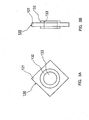
- FIG. 7A is a front view showing a disc-shaped impacting body, and
FIG. 7B is a sectional view thereof taken along the line 7B-7B in FIG. 7A in
an arrow direction.
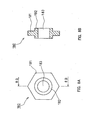
- FIG. 8A is a front view showing a regular-hexagonal impacting body,
and FIG. 8B is a sectional view thereof taken along the line 8B-8B in FIG. 8A
in an arrow direction.
- FIG. 9A is a front view showing a substantially bell-shaped
impacting body, and FIG. 9B is a side view thereof.
- FIG. 10A is a front view showing a modified pentagonal impacting
body, and FIG. 10B is a side view thereof.
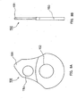
- FIG. 11A is a front view showing a substantially "9"-shaped
impacting body, and FIG. 11B is a sectional view thereof taken along the line
11B-11B in FIG. 11A in an arrow direction.
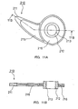
- FIG. 12A is a front view showing a substantially bow-shaped
impacting body, and FIG. 12B is a side view thereof.
- FIG. 13A is a front view showing a substantially bow-shaped
impacting body, and FIG. 13B is a side view thereof.
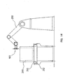
- FIG. 14 is a side view showing cutting and processing equipment in a
second embodiment of the present invention.
-
Best Mode for Carrying Out the Invention
-
The following is a description of embodiments of a cutting device and
a cutting method of the present invention, with reference to the
accompanying drawings.
(First Embodiment)
-
FIG. 1 is a top view showing a cutting device according to a first
embodiment of the present invention, and FIG. 2 is a sectional view thereof
taken along the line II-II in FIG. 1 in an arrow direction, showing the state of
cutting a workpiece as well.
-
A cutting device 100 in the first embodiment has a first rotating unit
110 and a second rotating unit 120 as shown in FIGs. 1 and 2.
-
The first rotating unit 110 has a pair of discs (rotors) 111, 111 that are
spaced at a predetermined distance and attached to a main shaft 112 with
their principal planes opposing each other, and impacting bodies (hard solid
bodies) 130 mounted rotatably to spindles 113 provided between the pair of
discs 111, 111. The main shaft 112 is connected to a rotating shaft of a
driving motor 115, so that the first rotating unit 110 is rotated about the
main shaft 112 serving as a rotational center. Four spindles 113 are
provided on the circumference of a circle, whose center corresponds to this
rotational center, in such a manner as to be spaced at equal angles.
-
Similarly, the second rotating unit 120 has a pair of discs (rotors) 121,
121 that are spaced at a predetermined distance and attached to a main shaft
122 with their principal planes opposing each other, and impacting bodies
(hard solid bodies) 140 mounted rotatably to spindles 123 provided between
the pair of discs 121, 121. The main shaft 122 is connected to a rotating
shaft of a driving motor 125, so that the second rotating unit 120 is rotated
about the main shaft 122 serving as a rotational center. Four spindles 123
are provided on the circumference of a circle, whose center corresponds to this
rotational center, in such a manner as to be spaced at equal angles.
-
The first rotating unit 110 and the second rotating unit 120 are held
by a common base 103 so that the directions of the axes of rotation thereof
are parallel and the principal planes of the discs 111 and the discs 121 are on
substantially the same plane, in other words, so that a circular path 117 of
cutting blades 131 at the tip of the impacting bodies 130 and a circular path
127 of cutting blades 141 at the tip of the impacting bodies 140 during the
rotation substantially are on the same plane. The base 103 is mounted on a
robot arm 251.
-
FIGs. 3A and 3B show a specific configuration of the impacting body
130. FIG. 3A is a front view, and FIG. 3B is a side view. As shown in these
figures, the square impacting body 130 has a shape such as the one obtained
by attaching a cylindrical body 132 with a through hole 133 to the central
portion of a plate member with a planar shape of a square and a
predetermined thickness. The cylindrical body 132 is made to have a length
larger than the thickness of the square plate member, thus securing
mechanical strength. Four corners 131 of the square plate member
correspond to cutting blades in a conventional tool and impact on the
workpiece. The impacting body 130 is attached to the rotating unit 110 by
passing the spindle 113 through the through hole 133. As shown in FIGs. 1
and 2, the impacting body 130 is attached so that a part of its periphery (in
particular, the cutting blade 131) is located beyond the periphery of the disc
111 when the rotating unit 110 rotates. In the device shown in FIGs. 1 and 2,
four impacting bodies 130 are arranged on the principal planes of the discs
111 so as to be spaced equally from each other.
-
FIGs. 4A and 4B show a specific configuration of the impacting body
140. FIG. 4A is a front view, and FIG. 4B is a side view. As shown in these
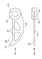
figures, the substantially bow-shaped impacting body 140 has a floating
portion 145, a through hole 143 provided at one end of the floating portion
145 and the cutting blade 141 provided at the other end of the floating
portion 145. The floating portion 145 has a shape approximately that of a
substantially-bow shape that is formed of a substantially circular-arc portion
and a chord extending between both ends of the circular-arc, or a
substantially-bow shape that is substantially the same as that of pieces
obtained by bisecting an ellipse or an oval along its longitudinal direction.
The cutting blade 141 is formed to be thick so as to be resistant to shock at
the time of impacting on the workpiece, the peripheral portion of the through
hole 143 is formed to be thick so as to be resistant to centrifugal force during
rotation, and other portions are formed to be thin so as to reduce weight.
The impacting body 140 is attached to the rotating unit 120 with its cutting
blade 141 facing forward in the rotational direction by passing the spindle
123 through the through hole 143. As shown in FIGs. 1 and 2, the impacting
body 140 is attached so that a part of its periphery (in particular, the cutting
blade 141) is located beyond the periphery of the disc 121 when the rotating
unit 120 rotates. In the device shown in FIGs. 1 and 2, four impacting
bodies 140 are arranged on the principal planes of the discs 121 so as to be
spaced equally from each other. The planar shape of the through hole 143
preferably is an ellipse as shown in FIGs. 4A and 4B. More accurately, the
planar shape of the through hole 143 is a circular-arc elliptical shape that is
formed by two circular arcs with different radii whose centers are the center
of gravity of the impacting body 140 and semicircles connecting both ends of
these two circular arcs in the circumferential direction. By forming the
through hole 143 to be a circular-arc elliptical hole whose center is the center
of gravity of the impacting body 140, the displacement of the impacting body
140 when the impacting body 140 rebounds in such a manner as to rotate
about its center of gravity after impacting on a workpiece can be absorbed
well, thus improving the cutting performance. Since a rotationally
symmetric impacting body such as the impacting body 130 shown in FIGs. 3A
and 3B has a center of gravity substantially corresponding to the center of
the through hole 133, the planar shape of the through hole 133 is formed to
be circular, thereby absorbing the above-mentioned displacement caused by
the rebound at the time of impacting.
-
A predetermined fitting gap 114 is provided between the spindle 113
and the through hole 133 of the impacting body 130. Similarly, a
predetermined fitting gap 124 is provided between the spindle 123 and the
through hole 143 of the impacting body 140. By providing the fitting gaps
114, 124, the impacts on the cutting blades 131, 141 and the spindles 113, 123
are relieved when the impacting bodies impact on the workpiece even though
the rotors 111, 121 rotate at a high speed, thus preventing components of the
rotating units 110, 120 such as the spindles from being damaged.
-
The following is a description of an example of cutting a workpiece
(an object to be processed) by using the above-described cutting device 100.
The description is directed to the case of cutting a workpiece 290 having a
layered structure including a steel plate layer 291, a urethane foam layer 292
and a resin plate layer 293 in this order as shown in FIG. 2. The cutting
device 100 and the workpiece 290 are arranged such that the directions of the
axes of rotation of the main shafts 112, 122 are substantially parallel with a
surface of the plate-like workpiece 290. Then, the cutting device 100 is
moved in the direction indicated by an arrow 109 while rotating the first
rotating unit 110 and the second rotating unit 120 at a high speed in the
directions indicated respectively by arrows 119, 129. The moving direction
109 is parallel with the principal planes of the discs 111, 121 and also with
the surface of the workpiece 290. Accordingly, the impacting bodies 130 of
the first rotating unit 110 first impact on the steel plate layer 291 on the
surface of the workpiece 290, and the steel plate layer 291 and a part of the
upper portion of the urethane layer 292 are cut, so that a groove having a
predetermined width and depth is formed on the upper surface of the
workpiece 290. Subsequently, the impacting bodies 140 of the second
rotating unit 120 advance along this groove, thus cutting the lower portion of
the urethane layer 292 and the resin plate layer 293, which have not been
subjected to the impacting bodies 130.
-
At this time, the rotating units are rotated so that at least either of
the impacting bodies 130 or the impacting bodies 140 impact on the
workpiece at least at the critical impact velocity of the workpiece 290. In the
above example, it is preferable that the impacting bodies 130 impacting on
the steel plate layer 291, which is made of a high hardness material and
difficult to cut, impact at least at the critical impact velocity of a material of
the steel plate layer 291. With respect to the rotational speed, a variation of
about ±10% is allowable due to the variation in power supply voltage or other
reasons.
-
The impact velocity of the impacting bodies 130 against the workpiece
290 naturally corresponds to the rotational speed of the pair of discs (rotors)
111. The present embodiment employs a rotational speed in a high
rotational speed range of, for example, 10,000 to 60,000 rpm as the rotational
speed of the pair of discs 111. The high rotational speed range enables the
impact force of the impacting bodies 130 to increase and the lifetime thereof
to be extended by an air-cooling effect and work hardening. In the cutting
device 100 shown in FIG. 1, four impacting bodies 130 are spaced equally
between the principal planes of the discs 111. Therefore, the impacting
frequency of the first rotating unit 110 against the workpiece 290 is at least
(10,000 rotations/minute) x four impacting bodies = 40,000 times/minute.
-
In the above example, the impacting bodies 140 of the second rotating
unit 120 need not be allowed to impact at least at the critical impact velocity
of the workpiece 290 (in particular, the urethane layer 292 and the resin plate
layer 293). Since the urethane layer 292 and the resin plate layer 293 have
a low hardness and do not cause a brittle fracture easily, even when the
impacting bodies 140 are allowed to impact at the critical impact velocity of
the workpiece or lower, only the vicinity of the part subjected to the impact is
smashed and can be cut easily. In such cases, it may be possible to choose to
rotate the second rotating unit 120 not at a high speed but at a low speed,
thereby saving a driving energy. This also eliminates the need for the design
that is resistant to a great centrifugal force generated at the time of
high-speed rotation, making it possible to reduce the size and weight of the
second rotating unit 120 and improve safety. Also, it becomes possible to
reduce the size of the driving motor 125. In this way, the equipment cost
and operating cost can be reduced. Of course, there are some cases where,
depending on a material of the layer to be cut mainly by the impacting bodies
140 of the second rotating unit 120, the impacting bodies 140 preferably are
allowed to impact at least at the critical impact velocity of this material.
-
As described above, in the cutting device 100 of the present
embodiment, the impacting bodies 130 of the first rotating unit 110 cut only
the top layer of the workpiece 290, and the impacting bodies 140 of the
following second rotating unit 120 cut deeply to the back surface thereof. In
the present embodiment, in order that the impacting bodies of these rotating
units have different cutting depths, the circular paths 117, 127 of the tips of
the cutting blades of the impacting bodies of these rotating units are made to
have different radii and the main shafts 112, 122 are made to have different
heights above (distances from) the surface of the workpiece 290 as shown in
FIG. 2. Simply changing the heights of the axes of rotation (the main shafts)
of these rotating units while keeping their configurations completely the
same also can change the cutting depths of the impacting bodies of these
rotating units. However, there are some cases where the circular path 117 of
the first rotating unit 110 preferably is designed to have a smaller radius
than the circular path 127 of the second rotating unit 120 by modifying the
shapes of the impacting bodies as described in the present embodiment. The
reason follows. In order to allow the impacting bodies to impact on the
workpiece at least at the critical impact velocity, the rotating unit has to be
rotated at a high speed. On the other hand, in order to cut the workpiece
having a certain thickness, the projecting length of the impacting bodies
beyond the disc during rotation has to be longer than the thickness of the
workpiece. Thus, there is a lower limit for the size of the impacting body.
When a large impacting body is attached to the rotating unit, the weight of
the impacting body and the distance from the rotational center to the center
of gravity of the impacting body increase. Therefore, as the impacting body
becomes larger, the centrifugal force generated at the time of high-speed
rotation increases in an accelerating manner. As a result, it becomes
necessary to design the device having a mechanical strength that can
withstand this centrifugal force, leading to a further increase in weight and
costs. Accordingly, when cutting the workpiece 290 having a layered
structure and whose surface and back layers have different critical impact
velocities as in the above example, the workpiece is disposed so that the steel
plate layer 291 having a large critical impact velocity can be cut first and the
circular path 117 of the first rotating unit 110 cutting the steel plate layer
291 is made to be smaller than the circular path 127 of the second rotating
unit 120. Consequently, the size of the impacting bodies 130 of the first
rotating unit 110 can be reduced, and thus their radius of gyration also
decreases, thus achieving a high-speed rotation of the first rotating unit 110
easily. On the other hand, since the rotational speed of the second rotating
unit 120 cutting the urethane layer 292 and the resin plate layer 293 having
a relatively small critical impact velocity can be made lower than that of the
first rotating unit 110, the strength design can be carried out relatively easily
even when providing large impacting bodies 140.
-
The cutting device of the present invention includes at least two
rotating units. There are the following problems in the case of cutting the
workpiece at one time with only a single rotating unit. For example, when
the workpiece is thick, the projecting length of the impacting bodies beyond
the disc at the time of rotation has to be greater than the workpiece thickness
in order to cut the workpiece at one time with one rotating unit. This
increases the size and weight of the impacting bodies. In order to rotate
them at a high speed, the mechanical strength needs to be improved, leading
to an increase in the weight of the rotating unit and higher costs as described
above. Also, when cutting the workpiece formed by layering different kinds
of materials, the impacting bodies have to be allowed to impact at least at the
largest critical impact velocity among those of the layered materials in order
to cut the workpiece at one time with one rotating unit. Thus, it is necessary
to rotate the rotating unit at a high speed. Therefore, the strength design
and driving mechanism of the rotating unit have to be brought into
correspondence with such a rotation, which brings about much waste.
Furthermore, when attempting to cut the workpiece 290 at one time with
only the second rotating unit 120 provided with, for example, the
substantially bow-shaped impacting bodies 140 with longer projecting
lengths, the impact on the difficult-to-machine steel plate layer 291 causes
each impacting body 140 to rebound and rotate about the spindle 123 and
then interfere with the impacting body 140 positioned toward the back in the
rotational direction, which is supposed to impact on the workpiece
subsequently. Also, when the workpiece is thick, the speed of the impacting
body lowers at some midpoint in the thickness direction of the workpiece, and
then this impacting body interferes with the subsequent impacting body 140
within the workpiece. Such interferences between the impacting bodies
deteriorate the cutting efficiency and the reliability of the cutting device.
When the intervals between the impacting bodies are increased for the
purpose of preventing the interference therebetween, the number of the
impacting bodies declines, leading to fewer impacting times and lower cutting
efficiency. For the above reasons, the workpiece is cut by sequentially
increasing the cutting depth using a plurality of the cutting units, thereby
achieving an excellent cutting performance with respect to a thick workpiece
and a workpiece formed by layering different kinds of materials. As becomes
clear from the above, when the workpiece is relatively thin, it also is possible
to cut the workpiece at one time with only a single rotating unit.
-
Impacting bodies attachable to the rotating units are not limited to
those shown in FIGs. 3A and 3B and FIGs. 4A and 4B, but can be those with
various shapes. In the following, examples of usable shapes of impacting
bodies will be described.
-
FIGs. 5A and 5B show a cruciform impacting body as an example of
an impacting body having projections at substantially equal angles on its
periphery, with FIG. 5A being a front view and FIG. 5B being a sectional view
of FIG. 5A taken along the line 5B-5B in an arrow direction. The cruciform
impacting body 150 has four rectangular projections 151, which are spaced at
equal angles in a circumferential direction, on the peripheral surface of a
cylindrical body 152 having a through hole 153. The rectangular projections
151 correspond to cutting blades in a conventional tool and impact on the
workpiece. The number of the rectangular projections (cutting blades) 151 is
not limited to four as in the present example but may be less (two, three) or
more (for example, five, six).
-
FIGs. 6A and 6B show a modified cruciform impacting body as
another example of an impacting body having projections at substantially
equal angles on its periphery, with FIG. 6A being a front view and FIG. 6B
being a side view. A modified cruciform impacting body 160 is formed by
modifying the shape of the rectangular projections 151 in the cruciform
impacting body 150 shown in FIGs. 5A and 5B. In other words, the modified
cruciform impacting body 160 has four substantially parallelogram
projections 161, which are spaced at equal angles in a circumferential
direction, on the peripheral surface of a cylindrical body 162 having a through
hole 163. The projections 161 are attached so that an acute end 161a on a
periphery of each projection 161 faces the direction of impacting on the
workpiece. The number of the substantially parallelogram projections 161 is
not limited to four as in the present example but may be less (two, three) or
more (for example, five, six). Also, instead of the substantially
parallelogram projections 161, projections such as substantially triangle
projections, arch-shaped projections or substantially semicircular projections
also may be provided in such a manner as to be spaced at equal angles.
-
FIGs. 7A and 7B show a disc-shaped impacting body 170, with FIG.
7A being a front view and FIG. 7B being a sectional view taken along the line
7B-7B in FIG. 7A in an arrow direction. The disc-shaped impacting body
170 has a shape such as the one obtained by inserting a cylindrical body 172
with a through hole 173 into the central portion of a ring cutting blade 171
with a predetermined thickness.
-
FIGs. 8A and 8B show a regular-hexagonal impacting body, with FIG.
8A being a front view and FIG. 8B being a sectional view taken along the line
8B-8B in FIG. 8A in an arrow direction. The regular-hexagonal impacting
body 180 has a shape such as the one obtained by inserting a cylindrical body
182 with a through hole 183 into the central portion of a plate member with
an outer shape of regular hexagon and a predetermined thickness. Six
comers 181 on the periphery of the plate member serve as cutting blades.
Instead of the regular hexagon, the plate member can have an outer shape of
other regular polygons such as a regular triangle, a regular pentagon and a
regular octagon.
-
FIGs. 9A and 9B show a substantially bell-shaped impacting body,
with FIG. 9A being a front view and FIG. 9B being a side view. A
substantially bell-shaped impacting body 190 has a planar shape of a bell
shape or a suitable variation thereof. An end corresponding to the portion
by which a bell is suspended is a cutting blade 191 for impacting on the
workpiece, and a wide region on the opposite side is provided with a through
hole 193 through which a spindle is passed. Furthermore, a through hole
194 is provided for reducing weight, and the region in which the through hole
194 is formed is thinner than the region in which the through hole 193 is
formed.
-
FIGs. 10A and 10B show a modified pentagonal impacting body, with
FIG. 10A being a front view and FIG. 10B being a side view. A modified
pentagonal impacting body 200 has a planar shape that is substantially the
same as a pentagon obtained by cutting off corners on both sides on one
shorter side of a rectangle. A resultant corner at the tip formed by cutting
off the corners on the both sides is a cutting blade 201 for impacting on the
workpiece. On the opposite side, a through hole 203 through which a
spindle is passed is formed .
-
FIGs. 11A and 11B show a substantially "9"-shaped impacting body,
with FIG. 11A being a front view and FIG. 11B being a sectional view taken
along the line 11B-11B in FIG. 11A in an arrow direction. A substantially
"9"-shaped impacting body 210 has a substantially disc-shaped plate 216
having a substantially circular (or substantially oval) shape and a
wedge-shaped portion 215, which are connected so as to form a substantially
"9" shape or a substantially "," (comma) shape. An end of the wedge-shaped
portion 215 is a cutting blade 211 for impacting on the workpiece. In
addition, the substantially central portion of the substantially disc-shaped
plate 216 is provided with a through hole 213 through which a spindle is
passed, and the periphery thereof is formed to be thick for raising the
mechanical strength. Furthermore, the edge portions of the substantially
disc-shaped plate 216 and the wedge-shaped portion 215 are formed to be
thick and inner regions thereof are formed to be thin for reducing weight
while maintaining the necessary mechanical strength.
-
FIGs. 12A and 12B show a substantially bow-shaped impacting body,
with FIG. 12A being a front view and FIG. 12B being a side view. A
substantially bow-shaped impacting body 220 shown in FIGs. 12A and 12B is
an example of modifying the substantially bow-shaped impacting body 140
shown in FIGs. 4A and 4B. As the substantially bow-shaped impacting body
140 shown in FIGs. 4A and 4B, the substantially bow-shaped impacting body
220 has a substantially bow-shaped floating portion 225, a through hole 223
having a circular-arc elliptical shape provided at one end of the floating
portion 225 and a cutting blade 221 provided at the other end of the floating
portion 225. The substantially bow-shaped impacting body 220 is different
from the substantially bow-shaped impacting body 140 shown in FIGs. 4A
and 4B in the following points. First, the peripheral region of the through
hole 223 through which a spindle is passed is formed to be still thicker, thus
improving a mechanical strength to resist a centrifugal force generated at the
time of rotation. Second, the floating portion 225 is provided with through
holes 224 so as to reduce weight, thus reducing the centrifugal force
generated at the time of rotation.
-
FIGs. 13A and 13B show another example of a substantially
bow-shaped impacting body, with FIG. 13A being a front view and FIG. 13B
being a side view. A substantially bow-shaped impacting body 230 shown in
FIGs. 13A and 13B is an example of modifying the substantially bow-shaped
impacting body 140 shown in FIGs. 4A and 4B. The substantially
bow-shaped impacting body 230 has a floating portion 235 like the
substantially bow-shaped impacting body 140 shown in FIGs. 4A and 4B, but
a portion corresponding to the chord of the bow is bent in the same direction
as the substantially circular arc portion in the impacting body 230, whereas it
is a straight line in the impacting body 140 shown in FIGs. 4A and 4B. As in
the substantially bow-shaped impacting body 140 shown in FIGs. 4A and 4B,
a through hole 233 having a circular-arc elliptical shape is formed at one end
of the floating portion 235 and a cutting blade 231 is formed at the other end
of the floating portion 235. In addition, as in the substantially bow-shaped
impacting body 220 shown in FIGs. 12A and 12B, the peripheral region of the
through hole 233 through which a spindle is passed is formed to be thick,
thus improving a mechanical strength to resist a centrifugal force generated
at the time of rotation.
-
The impacting body can have various shapes other than the above as
long as it has a through hole through which a spindle can be passed and a
cutting blade to impact on the workpiece. Furthermore, the tips of the
through hole and the cutting blade may be made thick for raising the
mechanical strength, while a through hole may be provided suitably or the
plate thickness may be reduced partially so as to reduce weight for the
purpose of reducing the centrifugal force that is generated.
-
Among the impacting bodies described above, impacting bodies that
are rotationally symmetric with respect to an axis of the through hole
through which a spindle is inserted such as the impacting body 130 (FIGs. 3A
and 3B), the impacting body 150 (FIGs. 5A and 5B), the impacting body 160
(FIGs. 6A and 6B), the impacting body 170 (FIGs. 7A and 7B) and the
impacting body 180 (FIGs. 8A and 8B) have a smaller projecting length
beyond the rotor but can achieve lighter weight. Therefore, they can be used
suitably as an impacting body of a rotating unit rotating at a very high speed
or a rotating unit that does not require a great cutting depth (the first
rotating unit 110 in the above example). On the other hand, impacting
bodies provided with a through hole through which a spindle is inserted at
one end of an oblong floating portion such as the impacting body 140 (FIGs.
4A and 4B), the impacting body 220 (FIGs. 12A and 12B) and the impacting
body 230 (FIGs. 13A and 13B) can achieve a larger projecting length beyond
the rotor so as to obtain a greater cutting depth, but are a relatively heavy
and have the center of gravity far from an axis of rotation of the rotating unit.
Accordingly, the strength to withstand the centrifugal force generated when
rotating the unit at a very high speed has to be considered. Therefore; they
can be used suitably as an impacting body of a rotating unit rotating at a
relatively low speed or a rotating unit that requires a great cutting depth (the
second rotating unit 120 in the above example). Furthermore, the shapes of
the impacting body 190 (FIGs. 9A and 9B), the impacting body 200 (FIGs.
10A and 10B) and the impacting body 210 (FIGs. 11A and 11B) have
intermediate characteristics between the above two groups and can be used
for both the first rotating unit 110 and the second rotating unit 120 in the
above example.
-
Besides the disc type, the rotors 111, 121 may have an arbitrary
shape such as a regular polygon. However, as a matter of course, the rotors
should be balanced during rotation.
-
Next, examples of dimensions and materials of the rotors and the
impacting bodies are described. In the cutting device according to the
embodiment shown in FIGs. 1 and 2, the disc 111 had a diameter of 100 mm
and a plate thickness of 5 mm and was made of carbon steel for machine
structural use, and the disc 121 had a diameter of 200 mm and a plate
thickness of 10 mm and was made of carbon steel for machine structural use.
The spindle 113 had a diameter of 10 mm and was made of carbon steel for
machine structural use or carbon tool steel (JIS code: SK2), and the spindle
123 had a diameter of 21 mm and was made of carbon steel for machine
structural use or carbon tool steel (JIS code: SK2). The impacting body 130
had a 34.2 mm x 34.2 mm square plate member with a thickness of 5 mm, the
cylindrical body 132 with an outer diameter of 25 mm and a length of 10 mm
and the through hole 133 with an inner diameter of 17 mm. The impacting
body 140 had a total length L0 of 200 mm, a length L1 from substantially the
center of the through hole 143 to the end of the cutting blade 141 of 160 mm,
the through hole 143 thereof had an inner dimension along its lengthwise
direction of 26 mm and that along its widthwise direction of 22 mm, and the
cutting blade 141, the peripheral portion of the through hole 143 and the
other portions had thicknesses of 6 mm, 10 mm and 5 mm, respectively, as
shown in FIGs. 4A and 4B. The impacting bodies 130 and 140 were made of
any one material selected from carbon steel for machine structural use (S45C),
carbon tool steel (SK2), high speed tool steel (SKH2), Ni-Cr steel (SNC631),
Ni-Cr-Mo steel (SNCM420), Cr-Mo steel (SCM430), chromium steel
(SCr430) and manganese steel for machine structural use (SMn433).
-
In the example of cutting a workpiece, which is shown in FIGs. 1 and
2, the disc 110 was rotated at 30,000 rpm in the direction indicated by the
arrow 119, and the impact velocity of the impacting bodies 130 against the
steel plate layer 291 (a 1-mm-thick cold-rolled steel sheet) as the top layer of
the workpiece 290 was set to be about 157 m/second (565 km/hour). Also,
the disc 120 was rotated at 3000 rpm in the direction indicated by the arrow
129, and the impact velocity of the impacting bodies 140 against the urethane
layer 292 (a 60-mm-thick urethane foam) and the resin plate layer 293 (a
1-mm-thick ABS resin (acrylonitrile-butadiene-styrene copolymer)) of the
workpiece 290 was set to be about 72 m/second (260 km/hour). The
workpiece 290 was fixed, and the robot arm 251 was controlled to move the
cutting device 100 at a moving speed for cutting of 50 mm/second in the
direction indicated by the arrow 109. In this case, the impacting frequencies
were (30,000 rotations/minute) × four impacting bodies = 120,000
times/minute for the impacting bodies 130 and (3,000 rotations/minute) x four
impacting bodies = 12,000 times/minute for the impacting bodies 140.
-
Since the main shaft 112 rotates at a high speed as described above, a
great centrifugal force acts on the impacting bodies 130. The centrifugal
force causes a high-speed compressive force accompanied with impacts in a
limited portion of the steel plate layer 291 including the surface subjected to
the impact by the cutting blades 131 of the impacting bodies 130 and the
vicinity of the impact surface. Thus, the top layer of the impact surface of
the steel plate layer 291 is smashed at a high speed instantaneously. Cut
scraps are in a minute granular state. It has been confirmed by a test that
the workpiece can be cut even when no sharp cutting blade is provided.
-
The impact velocity of the impacting bodies 140 against the urethane
layer 292 and the resin plate layer 293 is not greater than the critical impact
velocity of materials for these layers. Even when the impacting bodies 140
are allowed to impact on these layers at their critical impact velocity or lower,
unlike the case of the difficult-to-machine steel plate layer, only the vicinity
of the part subjected to the impact is smashed and the fracture does not
propagate widely. Thus, the workpiece 290 can be cut substantially along
the groove formed by the impacting bodies 130.
-
In the above, the impact velocities of the impacting bodies 130, 140
are not limited to the above-mentioned specific example and can be set freely
depending on the kind of a workpiece, cutting conditions, or the like as long
as at least either of them is at least the critical impact velocity of the
workpiece (when the workpiece is formed of a layered body including a
plurality of layers, the impact velocity of the impacting bodies cutting the
layer that is most difficult to cut in view of physical properties such as
hardness, brittleness and strength is considered to be at least at the critical
impact velocity of the material for this layer). Similarly, the number of
impacts by the impacting bodies 130, 140 per unit time also can be changed
depending on the kind of a workpiece, cutting conditions, or the like.
-
When the material of a workpiece is unknown, when a workpiece is
formed of a plurality of different kinds of members, or when a member whose
material is unknown hides in a part that cannot be seen from the outside,
such a workpiece can be cut excellently by setting the impact velocity of the
impacting bodies to be somewhat higher.
-
With respect to the material for the impacting bodies, members other
than metallic members also can be used freely as long as they are hard solid
bodies.
-
Furthermore, the number of the impacting bodies provided in one
rotating unit may be only one or at least two. In the case of providing a
plurality of the impacting bodies, it is preferable to provide them at equal
angles with respect to the rotational center of the rotors, because this results
in equal impact intervals to allow stable cutting. In the case of using only
one impacting body, a balancer (a weight) is provided to secure the rotational
balance.
-
It is preferable that the cutting blade of the impacting body provided
in the following rotating unit is designed to have substantially the same
thickness as or to be thinner than that provided in the foregoing rotating unit,
which cuts into the workpiece earlier. By cutting into the workpiece with
the impacting bodies having the same thickness or with decreasing thickness,
the following impacting bodies reliably can fit into a groove-like incised
portion formed on the workpiece by the foregoing impacting bodies.
-
Moreover, instead of spacing the pair of rotors so as to arrange the
impacting bodies therebetween, only one rotor may be used with the spindles
provided on one side thereof perpendicularly thereto with a cantilevered
support structure, so that the impacting bodies may be provided on these
spindles.
-
The rotor may be driven to rotate at a high speed using a general
spindle motor or the like.
-
The number of the rotating units is not limited to two as described
above but may be three or more. If three or more rotating units are used
and the workpiece is cut sequentially by increasing the cutting depth of the
impacting bodies of these units as described above, such a workpiece can be
cut excellently even when the workpiece is thick or has a multilayered
structure. In such cases, it is preferable that the impacting bodies of these
rotating units are allowed to impact on the workpiece at least at the critical
impact velocity of each material of the workpiece to be cut by the respective
units. However, as is already mentioned, there are some cases where,
depending on a material of the workpiece, the workpiece can be cut without
any problems even when not all the impacting bodies of a plurality of the
rotating units are allowed to impact at least at the critical impact velocity.
-
For example, when the steel plate layer 291 as the top layer of the
workpiece 290 is thick and thus the entire thickness thereof is difficult to cut
at one time with the first rotating unit in the above example, a third rotating
unit that has substantially the same configuration with the first rotating unit
is provided between the first rotating unit and the second rotating unit in the
cutting device shown in FIGs. 1 and 2. Then, the cutting depth is increased
in the order of the first, third and second rotating units, thus cutting the steel
plate layer 291 with the first rotating unit and the third rotating unit. In
this case, it is needless to say that the impacting bodies of the first and third
rotating units preferably are allowed to impact on the steel plate layer 291 at
least at the critical impact velocity of the steel plate layer 291.
-
The plurality of the rotating units constituting the cutting device do
not have to be attached to the common base as in the above example, but may
be supported and moved individually so as to move along cutting positions on
the workpiece sequentially. However, when they are mounted on the
common base, it is possible to control the movement of the cutting device as
one piece, allowing a simplification of equipment and cost reduction.
-
In addition, although the workpiece was cut by moving the cutting
device while fixing the workpiece in the above example, it also may be cut by
moving the workpiece while fixing the cutting device at a predetermined
position.
-
As described above, the impacting bodies of the present invention are
not provided with sharp cutting blades as in a conventional cutting tool. The
cutting principle of the present invention goes beyond a conventional
practical sense and enables even brittle members such as metal, resin, glass,
ceramics, or the like to be cut by a single cutting device without using sharp
cutting blades by providing the impacting bodies with a far higher speed than
that in a conventional cutting tool.
(Second Embodiment)
-
FIG. 14 shows a side view of cutting and processing equipment
according to a second embodiment of the present invention. The cutting and
processing equipment of the present embodiment has the configuration in
which the cutting device 100 of the first embodiment is mounted to a robot
arm.
-
In FIG. 14, numeral 100 indicates the cutting device described in the
first embodiment, numeral 250 indicates a commercially available robot
controlled with five axes, numeral 295 indicates a workpiece (an object to be
processed, for example, a case body of a household electric appliance or the
like), numeral 260 indicates a carrier pallet on which the workpiece 295 is
loaded, and numeral 262 indicates a roller conveyor for carrying the carrier
pallet 260. The cutting device 100 of the present invention is mounted to a
robot arm 251 at the tip of the robot 250 as shown in FIG. 1.
-
When the workpiece 295 loaded on the carrier pallet 260 is placed in
front of the cutting device 100, which is detected automatically, the cutting
device 100 mounted to the arm of the robot 250 is rotated and driven. Thus,
the periphery of the workpiece 295 is cut and processed in a predetermined
manner by the five-axes control function (not shown in the figure).
-
The above-mentioned equipment preferably is provided with the
following control device (not shown in the figure). The control device detects
at least one of an intrinsic oscillatory waveform and an intrinsic oscillation
frequency that are caused by the impact of the impacting bodies against the
workpiece 295, a load on driving motors 115, 125 for rotating the rotating
units 110, 120 and an outer shape of the workpiece 295 and controls and
changes at least one of the rotational speed of each rotating unit (the impact
velocity of the impacting bodies), a cutting depth and a relative speed and a
relative moving direction (for example, when the cutting is judged to be
difficult, the cutting device 100 may be reversed slightly) between the
rotating unit and the object to be processed. In this manner, even when the
workpiece 295 is formed of a plurality of members with different physical
properties, even when the material of the workpiece 295 is unknown, or even
when the internal structure of the workpiece 295 that cannot be seen from
the outside is unknown, the optimum cutting conditions can be set
automatically, thus achieving the automation of the cutting work.
-
Furthermore, the above-mentioned control device can be provided for
each rotating unit. In other words, the control device detects at least one of
the intrinsic oscillatory waveform and the intrinsic oscillation frequency that
are caused by the impact of the impacting bodies against the workpiece 295,
the load on the driving motor for rotating each rotating unit and the outer
shape of the workpiece and changes at least one of the rotational speed, the
cutting depth and the relative speed and the relative moving direction
between the rotating unit and the object to be processed for each of the
rotating units. In this manner, it is possible to set an appropriate cutting
condition for each rotating unit.
-
It is needless to say that the conveyor system may be a belt conveyor
or a chain conveyor.
-
Moreover, although FIG. 14 illustrated an example of mounting the
cutting device 100 of the first embodiment including the first and second
rotating units to one robot, the present invention is not limited thereto. For
example, it also is possible to provide a plurality of robots, each of which is
provided with one rotating unit, thereby cutting into the workpiece
sequentially.
-
The invention may be embodied in other specific forms without
departing from the spirit or essential characteristics thereof. The
embodiments disclosed in this application are to be considered in all respects
as illustrative and not restrictive, the scope of the invention being indicated
by the appended claims rather than by the foregoing description, all changes
that come within the meaning and range of equivalency of the claims are
intended to be embraced therein.