EP1405678B1 - Cartridges for dispensing fluent material - Google Patents
Cartridges for dispensing fluent material Download PDFInfo
- Publication number
- EP1405678B1 EP1405678B1 EP03029563A EP03029563A EP1405678B1 EP 1405678 B1 EP1405678 B1 EP 1405678B1 EP 03029563 A EP03029563 A EP 03029563A EP 03029563 A EP03029563 A EP 03029563A EP 1405678 B1 EP1405678 B1 EP 1405678B1
- Authority
- EP
- European Patent Office
- Prior art keywords
- cartridge
- nozzle
- piston
- tongue
- cartridge according
- Prior art date
- Legal status (The legal status is an assumption and is not a legal conclusion. Google has not performed a legal analysis and makes no representation as to the accuracy of the status listed.)
- Expired - Lifetime
Links
- 239000000463 material Substances 0.000 title claims abstract description 17
- 230000015572 biosynthetic process Effects 0.000 claims description 15
- 238000005755 formation reaction Methods 0.000 claims description 15
- 239000012530 fluid Substances 0.000 claims description 8
- 240000000254 Agrostemma githago Species 0.000 claims description 2
- 235000009899 Agrostemma githago Nutrition 0.000 claims description 2
- 238000010137 moulding (plastic) Methods 0.000 claims description 2
- 229920003023 plastic Polymers 0.000 abstract description 5
- 239000004033 plastic Substances 0.000 abstract description 5
- 229920005989 resin Polymers 0.000 description 21
- 239000011347 resin Substances 0.000 description 21
- 238000000034 method Methods 0.000 description 6
- 230000008878 coupling Effects 0.000 description 5
- 238000010168 coupling process Methods 0.000 description 5
- 238000005859 coupling reaction Methods 0.000 description 5
- 238000007789 sealing Methods 0.000 description 3
- 239000011324 bead Substances 0.000 description 2
- 238000010276 construction Methods 0.000 description 2
- 238000009877 rendering Methods 0.000 description 2
- 230000001419 dependent effect Effects 0.000 description 1
- 230000008021 deposition Effects 0.000 description 1
- 238000007598 dipping method Methods 0.000 description 1
- 238000005108 dry cleaning Methods 0.000 description 1
- 239000004744 fabric Substances 0.000 description 1
- 238000004519 manufacturing process Methods 0.000 description 1
- 238000012986 modification Methods 0.000 description 1
- 230000004048 modification Effects 0.000 description 1
- 239000002904 solvent Substances 0.000 description 1
- 238000010186 staining Methods 0.000 description 1
- 229920003002 synthetic resin Polymers 0.000 description 1
- 239000000057 synthetic resin Substances 0.000 description 1
- 229920001187 thermosetting polymer Polymers 0.000 description 1
Images



Classifications
-
- B—PERFORMING OPERATIONS; TRANSPORTING
- B05—SPRAYING OR ATOMISING IN GENERAL; APPLYING FLUENT MATERIALS TO SURFACES, IN GENERAL
- B05C—APPARATUS FOR APPLYING FLUENT MATERIALS TO SURFACES, IN GENERAL
- B05C17/00—Hand tools or apparatus using hand held tools, for applying liquids or other fluent materials to, for spreading applied liquids or other fluent materials on, or for partially removing applied liquids or other fluent materials from, surfaces
- B05C17/005—Hand tools or apparatus using hand held tools, for applying liquids or other fluent materials to, for spreading applied liquids or other fluent materials on, or for partially removing applied liquids or other fluent materials from, surfaces for discharging material from a reservoir or container located in or on the hand tool through an outlet orifice by pressure without using surface contacting members like pads or brushes
- B05C17/00503—Details of the outlet element
- B05C17/00516—Shape or geometry of the outlet orifice or the outlet element
-
- A—HUMAN NECESSITIES
- A41—WEARING APPAREL
- A41D—OUTERWEAR; PROTECTIVE GARMENTS; ACCESSORIES
- A41D1/00—Garments
- A41D1/06—Trousers
- A41D1/10—Means for maintaining the crease
-
- B—PERFORMING OPERATIONS; TRANSPORTING
- B05—SPRAYING OR ATOMISING IN GENERAL; APPLYING FLUENT MATERIALS TO SURFACES, IN GENERAL
- B05C—APPARATUS FOR APPLYING FLUENT MATERIALS TO SURFACES, IN GENERAL
- B05C17/00—Hand tools or apparatus using hand held tools, for applying liquids or other fluent materials to, for spreading applied liquids or other fluent materials on, or for partially removing applied liquids or other fluent materials from, surfaces
- B05C17/005—Hand tools or apparatus using hand held tools, for applying liquids or other fluent materials to, for spreading applied liquids or other fluent materials on, or for partially removing applied liquids or other fluent materials from, surfaces for discharging material from a reservoir or container located in or on the hand tool through an outlet orifice by pressure without using surface contacting members like pads or brushes
- B05C17/00596—The liquid or other fluent material being supplied from a rigid removable cartridge having no active dispensing means, i.e. the cartridge requiring cooperation with means of the handtool to expel the material
-
- B—PERFORMING OPERATIONS; TRANSPORTING
- B05—SPRAYING OR ATOMISING IN GENERAL; APPLYING FLUENT MATERIALS TO SURFACES, IN GENERAL
- B05C—APPARATUS FOR APPLYING FLUENT MATERIALS TO SURFACES, IN GENERAL
- B05C17/00—Hand tools or apparatus using hand held tools, for applying liquids or other fluent materials to, for spreading applied liquids or other fluent materials on, or for partially removing applied liquids or other fluent materials from, surfaces
- B05C17/005—Hand tools or apparatus using hand held tools, for applying liquids or other fluent materials to, for spreading applied liquids or other fluent materials on, or for partially removing applied liquids or other fluent materials from, surfaces for discharging material from a reservoir or container located in or on the hand tool through an outlet orifice by pressure without using surface contacting members like pads or brushes
- B05C17/015—Hand tools or apparatus using hand held tools, for applying liquids or other fluent materials to, for spreading applied liquids or other fluent materials on, or for partially removing applied liquids or other fluent materials from, surfaces for discharging material from a reservoir or container located in or on the hand tool through an outlet orifice by pressure without using surface contacting members like pads or brushes with pneumatically or hydraulically actuated piston or the like
Definitions
- This invention relates to a cartridge and cartridge/nozzle combinations for dispensing fluent material into creases or garments or fabrics.
- the cartridge or cartridge/nozzle combination has a dispensing aperture and the fluent material is of such viscosity that a pressure is needed to cause the material to be dispensed through the dispensing aperture.
- Cartridges of this type have been known for at least fifteen years, and one form of known cartridge is set forth in European Patent No.0059413, and is used in the application of crease setting composition (which forms the fluent material) to garment creases to render them more permanent.
- the crease setting composition originally used typically was a synthetic resin based material which is thermosetting so that it cures when heated to render the crease more permanent, but nowadays it is more usual to use a naturally setting composition, which is still resin based.
- the known cartridge comprises an elongate, plastic material body which contains the resin and has a piston therein at one end of the body.
- the interior communicates with a transverse bore, and into the bore is fitted (initially) a plug which prevents the resin from leaking out of the bore when the cartridge is not in use.
- the plug is removed and is replaced by a nozzle tube which is fitted into the bore.
- the nozzle tube is closed at one end, is hollow, has a hole therein communicating with the body interior, and at the other end has a nozzle outlet slit from which the resin is dispensed as a fine narrow ribbon, when pressure is applied to the piston.
- the pressure may be applied to the piston by mechanical means or by fluid pressure, specifically compressed air.
- the cartridge As the resin is dispensed, the cartridge is moved along the line of the crease of the garment, either by manual judgement, or by machine, the nozzle slit lying along the line of the crease.
- a major difficulty with the existing cartridge arrangements is the keeping of the nozzle slit in alignment with the crease and the body of the cartridge.
- various means have been tried, as these nozzles tend to be used in a rough way by operatives, it happens that the nozzle slit becomes out of alignment with crease by becoming twisted relative to the body, and the result is that the resin is not applied in the correct manner rendering the process inefficient at best and useless at worst.
- the cartridge is suspended to lie with the length direction extending vertically, with the cartridge free to swing to a limited extent as the garment, usually trousers, is pulled vertically past the cartridge. This swinging is needed to allow the cartridge to accommodate the widening shape of trousers from bottoms to the waistband.
- Conventional cartridges have not been able to operate totally effectively in such machines.
- DE-A-1954812 shows such a cartridge which includes a cap with a releasable bayonet fitting to the cartridge body.
- the present invention aims to provide an improved cartridge and cartridge/nozzle combination which has/have a number of novel and inventive features which overcome the difficulties mentioned above.
- the cartridge is also easier to make, and is easier to use.
- a cartridge for or containing a fluent composition to be dispensed therefrom through an aperture of the cartridge comprising a one piece plastic moulding defining a body containing or for containing the composition having an integral dispensing nozzle, the outlet of which forms the aperture of the cartridge for dispensing a ribbon of fluent composition the body containing a piston for dispensing the fluent material by the application of fluid under pressure on the piston, and a cap sealed to the body at the end opposing the nozzle, said cap having an integral fluid pressure connection by which the fluid pressure source can be connected to the cartridge to drive the piston and characterised in that the cap is permanently sealed to the body.
- the body is elongate and the slit extends in the direction of the length of the body.
- the nozzle is in the form of a narrow tongue projecting from the body at one end thereof.
- the nozzle sleeve bore is of constant cross section in the shape of the narrow slit, and it is also preferred that the body is elongate and has the tongue at one end thereof, and the nozzle slit extends in the direction of the length of the body when the nozzle is received in the tongue.
- the tongue is narrower in one direction than in the other, and the tongue lies with its wide direction lying in the length direction of the body.
- nozzle there is a range of sizes of nozzle, each having a different width of slit for the dispensing of different widths of ribbon of fluent material, and particular advantage is gained by providing that the nozzle or each nozzle has gripping means whereby the nozzle can be gripped and removed from or inserted into the cartridge tongue.
- the nozzle When the nozzle is inserted in the tongue, it is preferred that its sleeve portion is in the tongue bore and the gripping means is to the outside of the tongue.
- the nozzle and tongue have interengaging catch means to prevent the nozzle from being forced out of the tongue in use, and the catch means comprises a catch bead on at least one of the nozzle and tongue so that when the nozzle is applied the nozzle or tongue has to be snapped over the catch bead.
- the cartridge may have integral guide means thereon in the form of one or more fin formations which is or are adapted to lie in the crease to which the fluent material is to be applied, and the fin formation or fin formations may be aligned with the nozzle slit when the nozzle is inserted into the tongue.
- the body defines an axis extending in the length direction, and there are at least two fin formations which are spaced apart lengthwise of the body, and of which the edges which lie in the crease of the garment lie in a plane which lies at a slight angle to the said body axis, and when the nozzle is inserted into the tongue, it projects further from the body than the fin formations.
- the end of the nozzle having the slit lies at a slight angle to the body axis.
- the nozzle is of narrow shape (narrow rectangular in cross section) with a bore of constant cross section in the shape of the slit, which fits into the narrow tongue bore (of the same narrow rectangular cross section as the sleeve of the nozzle).
- This ensures exact alignment and avoidance of turning of the nozzle relative to the body, and the achievement of more consistently efficient operation of the process.
- the fin formation and design ensures more consistent results in the process where the cartridge is suspended for swinging movement as discussed above, by inclining the fin formation edges relative to the body axis.
- the nozzle slit being held securely in alignment with the body axis, and the fin formations also being so held, provides for a most exact and controlled application of the crease setting composition, not achievable in the prior art.
- the cartridge can be stored without using the oil bath, in that the nozzle bore is narrow, and the small amount of resin in the that bore can be allowed to harden (but the resin in the body of the cartridge will not), and the nozzle can simply be removed and replaced with another when the cartridge is again to be used.
- a small removable bung may be provide which is pushed into the nozzle bore when the cartridge is not in use.
- the cap is sealed to the body it has a stepped cross section, and the body has a corresponding stepped cross section, so that the cap and body at the sealed region fit together in an overlapping fashion, the overlapping parts being sealed together, and the stepped portion of the cap may lie to the outside or inside of the stepped portion of the body.
- the cap of body may additionally be held together by being screwed, bayonet or otherwise fitted together, and the parts may be additionally connected by a layer of the resin therebetween.
- a cartridge for dispensing crease setting composition in the form of a thermo-setting resin is indicated by reference numeral 10.
- the cartridge is a hollow elongate body, and in this example is of circular cross section, but it could be of other cross section as desired.
- the cartridge has a first end 12 which is for the reception of fluid under pressure, in this case compressed air, and a second end 14 which is the dispensing end of the cartridge, as will be clear hereinafter.
- the cartridge has an integral dispensing tongue 16 which along with a pair of guide skids 18 and 20 lies in the vertical symmetrical plane 22 (Fig. 2) of the cartridge.
- Fig. 1 is shown diagrammatically a source of compressed air, for example a compressor 24 which supplies via a pipe 26 containing a control valve 28, a supply of compressed air to a coupling 30 at the first end of the cartridge.
- a source of compressed air for example a compressor 24 which supplies via a pipe 26 containing a control valve 28, a supply of compressed air to a coupling 30 at the first end of the cartridge.
- the compressed air is supplied to the interior of the cartridge at the first end and drives a piston 32 inside the cartridge lengthwise from the front end towards the second end.
- the piston 32 is so driven, so the crease setting composition inside the cartridge is dispensed from the tongue 16 to an aperture therein.
- Fig. 1 also shows a table 34 for supporting a garment 36 (Figs 2 and 3), a crease 38 of which is to have the crease setting composition 40 (shown in Fig. 3) applied thereto.
- the apparatus is described as a table 34, it is in fact a long arm which is supported cantilever fashion from a fixed end 42, the other end 44 being free so that the garment can be placed thereover.
- the garment may typically be a pair of trousers of which the creases are to be rendered more permanent.
- the garment 36 is placed on the table 34 as illustrated in Fig. 2, and then the cartridge 10 is brought into position with the tongue 16 at the end of the garment adjacent the fixed end 42 of the table.
- Air under pressure is connected from the source 24 to the interior of the cartridge to cause the crease setting composition to be dispensed as shown at 42 in Fig. 3 in the form of a fine narrow ribbon into the crease 38.
- the operator moves the cartridge 10 as indicated by the arrow 44A in Fig. 1 along the line of the crease, and so the crease setting composition is thereby applied.
- the operator may control the supply of compressed air via the valve 28 which may in fact be foot operated. It could be hand operated or it could be operated by the positioning of the cartridge into the operative position, or by any other suitable means.
- Fig. 4 shows the cartridge in the full condition.
- the cartridge At its first end 12 the cartridge has an integral flange 52 to which is sealed a similar flange 54 of a plastic cap 56.
- the cap 56 also has the coupling pipe or tube 30 formed therein, and it may if required have a one-way valve 58 to prevent escape of the compressed air after it has been injected into the space behind the piston 32.
- Fig. 5 shows that each of the skids or skis 18 and 20 is provided at its free edge with a tapered cross section 60 to ensure that the edge will fit neatly into the garment crease.
- These edges also determine the location of the outlet end of the tongue 16 in relation to the garment material, as in fact the dispensing of the fluent composition from the tongue 16 has to be accurately controlled.
- the outer edge 62 of the tongue may need to be angled at a small angle X to the horizontal (e.g. 5°) so as to give the correct deposition of the ribbon of crease setting composition which is dispensed therefrom.
- Fig. 6 shows the cross section of the tongue 16, and it will be seen to be hollow and comprise a passage of constant width T which controls the thickness of the narrow ribbon which is dispensed from the tongue.
- the thickness T will be calculated dependent upon the type of garment which is to be treated. For coarser garments such as jeans, a thicker ribbon is required whilst for the medium and largest range of weight of garments a middle thickness T is selected, whilst for lightweight and fine garments the smallest thickness T must be selected. Typically these thicknesses may be 2mm, 1mm and 1 ⁇ 2mm.
- the tongue 16 At its outlet end, the tongue 16 has its edges chamfered as shown at 64 again for best fitting in the crease of the garment.
- the tongue 16 also in fact forms a dispensing nozzle in the form of a narrow outlet slit which is in alignment with the aligned edges of the skis 18 and 20.
- the tongue provides an aperture through which the material can be dispensed.
- the interior defines a shallow conical surface to match the shape of the front of the piston 32 to give maximum dispensing of the material, or the piston and may be designed to the shape of the end of the body to ensure maximum dispensing of the composition.
- Fig. 4 wherein the tongue 16 also forms the dispensing nozzle, it may be necessary to provide a narrow isolating plug or bung which fits into the end of the tongue to close the outlet thereof so that the material in the tongue will not harden when the cartridge is stored when not in use.
- this particular form of cartridge can be stored with the tongue 16 dipping into an oil isolating bath of known type.
- the advantage of the cartridge arrangement shown in Fig. 4 is the provision of the integral tongue 16 which defines the outlet ribbon size, and it is not necessary to manufacture separate nozzles defining the ribbon size as in the conventional arrangement. Also the integral tongue and fins 20, 18 ensure fixed alignment between the crease and cartridge, and the use of two integral fins ensures excellent stability of the cartridge during use.
- Figs. 7 and 8 however indicate another embodiment of the present invention and referring to Figs. 7 and 8, the tongue 16 is still provided and is shown in these figures, but in this case it will have an interior width W as shown in Figure 8 which is greater than the largest thickness of ribbon to be dispensed from the cartridge.
- a removable nozzle 70 is applied to the outlet end of the tongue 16.
- the nozzle 70 as shown in Fig. 8 is of special construction, and is provided with a sleeve portion 72 which fits inside the passage of the tongue 16 basically as shown in Fig. 8, but the top 72A of the sleeve 72 preferably extends for the length of the tongue so as to lie flush with the interior of the body.
- the nozzle 70 forms a seal with the tongue 16 in the region 74 around the end of the tongue, and the sleeve portion 72 has a through passage 76 which forms the nozzle passage and dictates the final thickness of the ribbon which emerges from the nozzle 70.
- the nozzle 70 can be any of several sizes so as to define the different widths as indicated in dotted lines at 78 and 80.
- the nozzle 70 has bulbous wings 82 and 84 which form finger grips whereby the nozzle can be gripped and pulled from the tongue 16.
- these may be interengaging catch means on the sleeve and tongue to ensure that the parts have to be snapped together and apart. This ensures correct connection and provides a means resisting detachments the nozzle in use.
- the cartridge with a nozzle 70 fitted can be left standing overnight without being arranged to dip into a bath of oil because as the nozzle 70 is provided with a sleeve portion 72, there is provided a long length of narrow passage in which the material can harden, and the user simply removes the nozzle 70 with the hardened composition therein and throws it away, and inserts a new nozzle.
- These nozzles are small plastic items and are particularly inexpensive and therefore this is a convenient method of operation and it removes the messiness and undesirable characteristics of using a bath of oil.
- Fig. 9 shows basically the arrangement of Fig. 4 but embodying the detachable nozzle arrangement of Figs 7 and 8, with modifications.
- the piston 100 is of modified form in that it has a bevelled face 102 adapted to the shape of the bevelled end of the interior of the body, to maximise dispensing of the composition.
- the piston has sealing ring 103 of known form and in a rear recess 105 of the piston is fitted a known non-return blade spring (not shown), which does not resist forward movement of the piston, but resists reverse movement by digging into the wall of the body if any attempt is made to move the piston in the reverse direction.
- the end cap 104 which is sealed to the body 106 is so sealed by the means shown in Fig. 10, wherein the stepped end 104A of the cap 104 is fitted over (it could be fitted into) a corresponding stepped end 106A of the body 106, and the overlapped portions are sealed together (by any suitable means).
- the fin formations 110, 112 have their lower edges on a plane 114 which lies at a slight angle Y to the axis 116 of the body 106 of the cartridge, which enables the cartridge to be used in the vertical arrangement referred to herein.
- This cartridge can also be used in the conventional way.
- the nozzle 120 and the tongue 122 are designed so that the nozzle tip lies slightly proud of the fin formations 110, 112, but angled for example at the same angle Y, so that the tip lies basically in the same inclined plane 114.
- a spike shown in dotted lines and indicated by the reference Z in Fig. 4, which engages the piston 32 at the end of the stroke and causes it to tilt or cockle under the air pressure.
- the spike may puncture the piston as it reaches the end of its travel.
- the piston skirt may be perforated or may become perforated or an air passage may be created at a certain position of the piston along the body so that air can leak past the piston and out of the nozzle. This has the advantage that the cartridge will have an audible indication (the escape of air) of when the resin has been used up.
- the aperture prevents the refilling of the cartridge from the nozzle end.
- the piston will be fitted with hook step or other non return means which engages the bore of the body for example in a recess or shoulder, when the piston reaches a predetermined position, preventing its return along the inside of the body.
- the hook means may be one or more flaps which are kept alongside the body bore until it or they reach the recess, when they spring or are forced outwards into the recess or the shoulder.
Landscapes
- Engineering & Computer Science (AREA)
- Mechanical Engineering (AREA)
- Physics & Mathematics (AREA)
- Geometry (AREA)
- Textile Engineering (AREA)
- Coating Apparatus (AREA)
- Containers And Packaging Bodies Having A Special Means To Remove Contents (AREA)
- Treatment Of Fiber Materials (AREA)
- Dental Tools And Instruments Or Auxiliary Dental Instruments (AREA)
- Paper (AREA)
- Processing And Handling Of Plastics And Other Materials For Molding In General (AREA)
- Crystals, And After-Treatments Of Crystals (AREA)
- Prostheses (AREA)
- Packaging Of Annular Or Rod-Shaped Articles, Wearing Apparel, Cassettes, Or The Like (AREA)
- Agricultural Chemicals And Associated Chemicals (AREA)
- Polymerisation Methods In General (AREA)
- Cosmetics (AREA)
- Beverage Vending Machines With Cups, And Gas Or Electricity Vending Machines (AREA)
- Spinning Methods And Devices For Manufacturing Artificial Fibers (AREA)
Abstract
Description
- This invention relates to a cartridge and cartridge/nozzle combinations for dispensing fluent material into creases or garments or fabrics. The cartridge or cartridge/nozzle combination has a dispensing aperture and the fluent material is of such viscosity that a pressure is needed to cause the material to be dispensed through the dispensing aperture.
- Cartridges of this type have been known for at least fifteen years, and one form of known cartridge is set forth in European Patent No.0059413, and is used in the application of crease setting composition (which forms the fluent material) to garment creases to render them more permanent. The crease setting composition originally used typically was a synthetic resin based material which is thermosetting so that it cures when heated to render the crease more permanent, but nowadays it is more usual to use a naturally setting composition, which is still resin based. The known cartridge comprises an elongate, plastic material body which contains the resin and has a piston therein at one end of the body. At the other end, the interior communicates with a transverse bore, and into the bore is fitted (initially) a plug which prevents the resin from leaking out of the bore when the cartridge is not in use. When the cartridge is to be used, the plug is removed and is replaced by a nozzle tube which is fitted into the bore.
- The nozzle tube is closed at one end, is hollow, has a hole therein communicating with the body interior, and at the other end has a nozzle outlet slit from which the resin is dispensed as a fine narrow ribbon, when pressure is applied to the piston. The pressure may be applied to the piston by mechanical means or by fluid pressure, specifically compressed air.
- As the resin is dispensed, the cartridge is moved along the line of the crease of the garment, either by manual judgement, or by machine, the nozzle slit lying along the line of the crease.
- When the cartridge is exhausted of resin, it is thrown away. However, it is often the case that a cartridge may be used periodically depending upon demand, and when it is not in use, but still retains some useable resin, it is stored.
- The system has been successful and the components thereof have operated satisfactorily for many years, but there is now a demand for better performance, in that in attempts to prevent the resin at the nozzle outlet from hardening, for example by being left exposed to the atmosphere when stored, it has become the recommended practice to put the cartridge when stored in a cradle device so that the nozzle tip lies in a bath of oil. The oil prevents the air from coming into contact with the nozzle tip, and so prevents the residual resin in the nozzle tip from curing.
- This use of oil is not really satisfactory in that the oil may be spilled if the cradle is knocked, and also there is the possibility that the oil will come into contact with the garment being treated, which can result in an undesired staining of the garment, and removal of the stain requires the use of solvent or requires dry cleaning. This is a considerable disadvantage to the person providing the permanent creasing service.
- A major difficulty with the existing cartridge arrangements is the keeping of the nozzle slit in alignment with the crease and the body of the cartridge. Although various means have been tried, as these nozzles tend to be used in a rough way by operatives, it happens that the nozzle slit becomes out of alignment with crease by becoming twisted relative to the body, and the result is that the resin is not applied in the correct manner rendering the process inefficient at best and useless at worst.
- Again, in some machines the cartridge is suspended to lie with the length direction extending vertically, with the cartridge free to swing to a limited extent as the garment, usually trousers, is pulled vertically past the cartridge. This swinging is needed to allow the cartridge to accommodate the widening shape of trousers from bottoms to the waistband. Conventional cartridges have not been able to operate totally effectively in such machines.
- Additionally, when use is made of compressed air to force the piston along the body for the dispensing of the resin, a removable plug is placed in the end of the body to enable the connection of the air supply, and that plug must make air tight contact with the body for the driving by the compressed air to be effective. This can cause a problem, and special coupling devices are needed. These coupling devices are difficult to insert and remove properly, and operators find them difficult to work with as they are or soon become very tight.
- Finally, by the use of a removable plug to form the mounting for the air supply coupling, there is the possibility that the cartridges can be refilled by removing the plug. Refilling of the cartridges is not recommended, as invariably there will be residue of resin from the first filling which may be cured, and can cause inefficiencies in cartridge operation, leading to unsatisfactory results. Also, air can become trapped in the cartridge which causes a resin quality problem, and for best results in any event a used cartridge should be cleaned before reuse.
- DE-A-1954812 shows such a cartridge which includes a cap with a releasable bayonet fitting to the cartridge body.
- The present invention aims to provide an improved cartridge and cartridge/nozzle combination which has/have a number of novel and inventive features which overcome the difficulties mentioned above. The cartridge is also easier to make, and is easier to use.
- According to the invention there is provided, in a first aspect, a cartridge for or containing a fluent composition to be dispensed therefrom through an aperture of the cartridge, said cartridge comprising a one piece plastic moulding defining a body containing or for containing the composition having an integral dispensing nozzle, the outlet of which forms the aperture of the cartridge for dispensing a ribbon of fluent composition the body containing a piston for dispensing the fluent material by the application of fluid under pressure on the piston, and a cap sealed to the body at the end opposing the nozzle, said cap having an integral fluid pressure connection by which the fluid pressure source can be connected to the cartridge to drive the piston and characterised in that the cap is permanently sealed to the body.
- Preferably, the body is elongate and the slit extends in the direction of the length of the body.
- Preferably, the nozzle is in the form of a narrow tongue projecting from the body at one end thereof.
- Preferably, the nozzle sleeve bore is of constant cross section in the shape of the narrow slit, and it is also preferred that the body is elongate and has the tongue at one end thereof, and the nozzle slit extends in the direction of the length of the body when the nozzle is received in the tongue.
- In one arrangement, the tongue is narrower in one direction than in the other, and the tongue lies with its wide direction lying in the length direction of the body.
- It is preferred that there is a range of sizes of nozzle, each having a different width of slit for the dispensing of different widths of ribbon of fluent material, and particular advantage is gained by providing that the nozzle or each nozzle has gripping means whereby the nozzle can be gripped and removed from or inserted into the cartridge tongue.
- When the nozzle is inserted in the tongue, it is preferred that its sleeve portion is in the tongue bore and the gripping means is to the outside of the tongue.
- Preferably the nozzle and tongue have interengaging catch means to prevent the nozzle from being forced out of the tongue in use, and the catch means comprises a catch bead on at least one of the nozzle and tongue so that when the nozzle is applied the nozzle or tongue has to be snapped over the catch bead.
- The cartridge may have integral guide means thereon in the form of one or more fin formations which is or are adapted to lie in the crease to which the fluent material is to be applied, and the fin formation or fin formations may be aligned with the nozzle slit when the nozzle is inserted into the tongue. Specifically, the body defines an axis extending in the length direction, and there are at least two fin formations which are spaced apart lengthwise of the body, and of which the edges which lie in the crease of the garment lie in a plane which lies at a slight angle to the said body axis, and when the nozzle is inserted into the tongue, it projects further from the body than the fin formations.
- To ensure best application of resin to the crease, the end of the nozzle having the slit lies at a slight angle to the body axis.
- By preferred features exact and fixed alignment of the nozzle with the body axis can be achieved, and by making the fin formations integral with the body, further alignment security is achieved. Of particular advantage is that the nozzle is of narrow shape (narrow rectangular in cross section) with a bore of constant cross section in the shape of the slit, which fits into the narrow tongue bore (of the same narrow rectangular cross section as the sleeve of the nozzle). This ensures exact alignment and avoidance of turning of the nozzle relative to the body, and the achievement of more consistently efficient operation of the process. The fin formation and design ensures more consistent results in the process where the cartridge is suspended for swinging movement as discussed above, by inclining the fin formation edges relative to the body axis. The nozzle slit being held securely in alignment with the body axis, and the fin formations also being so held, provides for a most exact and controlled application of the crease setting composition, not achievable in the prior art.
- Also, by providing a sleeve portion which enters the tongue of the cartridge, when the cartridge is filled with resin, the cartridge can be stored without using the oil bath, in that the nozzle bore is narrow, and the small amount of resin in the that bore can be allowed to harden (but the resin in the body of the cartridge will not), and the nozzle can simply be removed and replaced with another when the cartridge is again to be used. As an alternative, a small removable bung may be provide which is pushed into the nozzle bore when the cartridge is not in use.
- Preferably where the cap is sealed to the body it has a stepped cross section, and the body has a corresponding stepped cross section, so that the cap and body at the sealed region fit together in an overlapping fashion, the overlapping parts being sealed together, and the stepped portion of the cap may lie to the outside or inside of the stepped portion of the body. The cap of body may additionally be held together by being screwed, bayonet or otherwise fitted together, and the parts may be additionally connected by a layer of the resin therebetween.
- By permanently sealing the cap to the body, refilling is prevented, and also there is no danger of the atmosphere reaching the resin at that end of the cartridge body.
- The various aspects of the invention can be used independently of one another or in any combination.
- An example of a cartridge/nozzle combination embodying the aspects of the present invention will now be described, by way of example, with reference to the accompanying drawings, wherein
- Fig. 1 shows a diagrammatic arrangement indicating the operation of a cartridge according to the present invention;
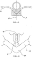
- Fig. 2 is an enlarged sectional elevation taken on the line 2-2 in Fig. 1;
- Fig. 3 is a sectional elevation to an even further enlarged scale taken on the line 3-3 in Fig. 1;
- Fig. 4 is an enlarged sectional view of the cartridge shown in Fig. 1, and in accordance with a first aspect of the invention;
- Fig. 5 is a sectional elevation to an enlarged scale taken on the line 5-5 of Fig. 1;
- Fig. 6 is a sectional elevation to an enlarged scale taken on the line 6-6 in Fig. 4;
- Fig. 7 is a side view showing a portion of the cartridge with a removable nozzle in accordance with another embodiment of the present invention;
- Fig. 8 is a sectional elevation taken on the line 7-7 in Figure 7 to an increased scale;
- Fig. 9 is a side view of a practical arrangement of the cartridge of Figure 4 embodying the nozzle of Figs. 7 and 8; and
- Fig 10 is a sectional view of the ringed detail of Fig. 9.
- Referring to the drawings, a cartridge for dispensing crease setting composition in the form of a thermo-setting resin is indicated by
reference numeral 10. The cartridge is a hollow elongate body, and in this example is of circular cross section, but it could be of other cross section as desired. The cartridge has afirst end 12 which is for the reception of fluid under pressure, in this case compressed air, and asecond end 14 which is the dispensing end of the cartridge, as will be clear hereinafter. - At the dispensing end, the cartridge has an
integral dispensing tongue 16 which along with a pair of guide skids 18 and 20 lies in the vertical symmetrical plane 22 (Fig. 2) of the cartridge. - In Fig. 1 is shown diagrammatically a source of compressed air, for example a
compressor 24 which supplies via apipe 26 containing acontrol valve 28, a supply of compressed air to acoupling 30 at the first end of the cartridge. As will be explained, the compressed air is supplied to the interior of the cartridge at the first end and drives apiston 32 inside the cartridge lengthwise from the front end towards the second end. As thepiston 32 is so driven, so the crease setting composition inside the cartridge is dispensed from thetongue 16 to an aperture therein. - Fig. 1 also shows a table 34 for supporting a garment 36 (Figs 2 and 3), a
crease 38 of which is to have the crease setting composition 40 (shown in Fig. 3) applied thereto. - Although the apparatus is described as a table 34, it is in fact a long arm which is supported cantilever fashion from a
fixed end 42, theother end 44 being free so that the garment can be placed thereover. - The garment may typically be a pair of trousers of which the creases are to be rendered more permanent.
- In the operation of the apparatus and cartridge the
garment 36 is placed on the table 34 as illustrated in Fig. 2, and then thecartridge 10 is brought into position with thetongue 16 at the end of the garment adjacent thefixed end 42 of the table. Air under pressure is connected from thesource 24 to the interior of the cartridge to cause the crease setting composition to be dispensed as shown at 42 in Fig. 3 in the form of a fine narrow ribbon into thecrease 38. At the same time the operator moves thecartridge 10 as indicated by thearrow 44A in Fig. 1 along the line of the crease, and so the crease setting composition is thereby applied. The operator may control the supply of compressed air via thevalve 28 which may in fact be foot operated. It could be hand operated or it could be operated by the positioning of the cartridge into the operative position, or by any other suitable means. - This basic method of operation, although not particulars of the cartridge, is known and has been practised for many years and continues to be a successful commercial operation.
- The present invention is concerned with the construction of the cartridge, and if reference is now made to Fig. 4, the
cartridge 10 is illustrated in cross sectional elevation. It will be seen that thecartridge 10 has abody 50 and thetongue 16 is integral with the body, the body and tongue being formed in a one-piece plastics moulded component. Also integral with the body are the ski guides 18 and 20. Thepiston 32 is a sealing, sliding fit inside thebody 10 so as to trap a quantity ofcrease setting composition 40 to be dispensed. Fig. 4 shows the cartridge in the full condition. - At its
first end 12 the cartridge has anintegral flange 52 to which is sealed asimilar flange 54 of aplastic cap 56. Thecap 56 also has the coupling pipe ortube 30 formed therein, and it may if required have a one-way valve 58 to prevent escape of the compressed air after it has been injected into the space behind thepiston 32. - Fig. 5 shows that each of the skids or
skis tapered cross section 60 to ensure that the edge will fit neatly into the garment crease. These edges also determine the location of the outlet end of thetongue 16 in relation to the garment material, as in fact the dispensing of the fluent composition from thetongue 16 has to be accurately controlled. Theouter edge 62 of the tongue may need to be angled at a small angle X to the horizontal (e.g. 5°) so as to give the correct deposition of the ribbon of crease setting composition which is dispensed therefrom. - Fig. 6 shows the cross section of the
tongue 16, and it will be seen to be hollow and comprise a passage of constant width T which controls the thickness of the narrow ribbon which is dispensed from the tongue. The thickness T will be calculated dependent upon the type of garment which is to be treated. For coarser garments such as jeans, a thicker ribbon is required whilst for the medium and largest range of weight of garments a middle thickness T is selected, whilst for lightweight and fine garments the smallest thickness T must be selected. Typically these thicknesses may be 2mm, 1mm and ½mm. - At its outlet end, the
tongue 16 has its edges chamfered as shown at 64 again for best fitting in the crease of the garment. - In the arrangement of Fig. 4, the
tongue 16 also in fact forms a dispensing nozzle in the form of a narrow outlet slit which is in alignment with the aligned edges of theskis body 10 at the dispensingend 14 the interior defines a shallow conical surface to match the shape of the front of thepiston 32 to give maximum dispensing of the material, or the piston and may be designed to the shape of the end of the body to ensure maximum dispensing of the composition. - With the arrangement of Fig. 4, wherein the
tongue 16 also forms the dispensing nozzle, it may be necessary to provide a narrow isolating plug or bung which fits into the end of the tongue to close the outlet thereof so that the material in the tongue will not harden when the cartridge is stored when not in use. Alternatively, this particular form of cartridge can be stored with thetongue 16 dipping into an oil isolating bath of known type. - The advantage of the cartridge arrangement shown in Fig. 4 is the provision of the
integral tongue 16 which defines the outlet ribbon size, and it is not necessary to manufacture separate nozzles defining the ribbon size as in the conventional arrangement. Also the integral tongue andfins - Figs. 7 and 8 however indicate another embodiment of the present invention and referring to Figs. 7 and 8, the
tongue 16 is still provided and is shown in these figures, but in this case it will have an interior width W as shown in Figure 8 which is greater than the largest thickness of ribbon to be dispensed from the cartridge. To define the finished ribbon thickness aremovable nozzle 70 is applied to the outlet end of thetongue 16. Thenozzle 70 as shown in Fig. 8 is of special construction, and is provided with asleeve portion 72 which fits inside the passage of thetongue 16 basically as shown in Fig. 8, but the top 72A of thesleeve 72 preferably extends for the length of the tongue so as to lie flush with the interior of the body. Thenozzle 70 forms a seal with thetongue 16 in theregion 74 around the end of the tongue, and thesleeve portion 72 has a throughpassage 76 which forms the nozzle passage and dictates the final thickness of the ribbon which emerges from thenozzle 70. Thenozzle 70 can be any of several sizes so as to define the different widths as indicated in dotted lines at 78 and 80. - As also shown in Fig. 8, the
nozzle 70 hasbulbous wings tongue 16. In this connection these may be interengaging catch means on the sleeve and tongue to ensure that the parts have to be snapped together and apart. This ensures correct connection and provides a means resisting detachments the nozzle in use. - The advantage of using this arrangement is that the cartridge with a
nozzle 70 fitted can be left standing overnight without being arranged to dip into a bath of oil because as thenozzle 70 is provided with asleeve portion 72, there is provided a long length of narrow passage in which the material can harden, and the user simply removes thenozzle 70 with the hardened composition therein and throws it away, and inserts a new nozzle. These nozzles are small plastic items and are particularly inexpensive and therefore this is a convenient method of operation and it removes the messiness and undesirable characteristics of using a bath of oil. - Fig. 9 shows basically the arrangement of Fig. 4 but embodying the detachable nozzle arrangement of Figs 7 and 8, with modifications. Firstly, the
piston 100 is of modified form in that it has a bevelledface 102 adapted to the shape of the bevelled end of the interior of the body, to maximise dispensing of the composition. Also, the piston has sealingring 103 of known form and in arear recess 105 of the piston is fitted a known non-return blade spring (not shown), which does not resist forward movement of the piston, but resists reverse movement by digging into the wall of the body if any attempt is made to move the piston in the reverse direction. - Secondly, the
end cap 104 which is sealed to thebody 106 is so sealed by the means shown in Fig. 10, wherein the steppedend 104A of thecap 104 is fitted over (it could be fitted into) a corresponding stepped end 106A of thebody 106, and the overlapped portions are sealed together (by any suitable means). - Also, the
fin formations plane 114 which lies at a slight angle Y to theaxis 116 of thebody 106 of the cartridge, which enables the cartridge to be used in the vertical arrangement referred to herein. This cartridge can also be used in the conventional way. Thenozzle 120 and thetongue 122 are designed so that the nozzle tip lies slightly proud of thefin formations inclined plane 114. - By the present invention in each of its various aspects taken alone or in combination, there is provided a particularly advantageous and novel cartridge rendering the successful crease setting application methods more convenient and even further improved.
- In a modified arrangement, which could be included in the embodiments set forth, there may be means for preventing refilling of the cartridge from the nozzle end. The means may take any forms and several are described and or indicated below.
- In a first arrangement, inside the cartridge body is moulded a spike shown in dotted lines and indicated by the reference Z in Fig. 4, which engages the
piston 32 at the end of the stroke and causes it to tilt or cockle under the air pressure. Alternatively, the spike may puncture the piston as it reaches the end of its travel. Also, the piston skirt may be perforated or may become perforated or an air passage may be created at a certain position of the piston along the body so that air can leak past the piston and out of the nozzle. This has the advantage that the cartridge will have an audible indication (the escape of air) of when the resin has been used up. The aperture prevents the refilling of the cartridge from the nozzle end. In another arrangement, the piston will be fitted with hook step or other non return means which engages the bore of the body for example in a recess or shoulder, when the piston reaches a predetermined position, preventing its return along the inside of the body. The hook means may be one or more flaps which are kept alongside the body bore until it or they reach the recess, when they spring or are forced outwards into the recess or the shoulder. - This aspect of the invention can be used with the other aspects herein set forth.
Claims (12)
- A cartridge (10) for or containing a fluent composition (40) to be dispensed therefrom through an aperture of the cartridge, said cartridge comprising a one piece plastic moulding defining a body containing or for containing the composition having an integral dispensing nozzle, the outlet of which forms the aperture of the cartridge for dispensing a ribbon of fluent composition, the body containing a piston (32, 100) for dispensing the fluent material by the application of fluid under pressure on the piston, and a cap (56, 104) sealed to the body at the end opposing the nozzle, said cap having an integral fluid pressure connection (30) by which the fluid pressure source can be connected to the cartridge to drive the piston and characterised in that the cap (56, 104) is permanently sealed to the body.
- A cartridge according to claim 1, wherein the body is elongate and the aperture extends in the direction of the length of the body.
- A cartridge according to claim 2, wherein the nozzle is in the form of a narrow tongue projecting from the body at one end thereof.
- A cartridge according to claim 1, wherein the body includes an integral fin formation or fin formations aligned with the longitudinal axis of the body.
- A cartridge according to claim 4, wherein the body defines an axis extending in the length direction, and there are at least two fin formations which are spaced apart lengthways of the body, and of which the edges lie in the crease of the garment lie in a plane which lies at a slight angle to the said body axis.
- The cartridge according to claim 4, wherein, when the nozzle is inserted into the tongue, it projects further from the body than the fin formations.
- A cartridge according to claim 6 wherein the end of the nozzle having the aperture lies at a slight angle to the body axis.
- A cartridge according to claim 1, wherein the cap is sealed to the body with a stepped cross section, and the body has a corresponding stepped cross section, so that the cap and body at the sealed region fit together I an overlapping fashion, the overlapping parts being sealed together.
- A cartridge according to claim 1, wherein the stepped portion of the cap lies to the outside of the stepped portion of the body.
- A cartridge according to claim 1 wherein there are provided means on the body adapted to co-operate with the piston after the piston has travelled a predetermined distance along the length of the body, to prevent the piston from being moved in the reverse direction.
- A cartridge according to claim 10, wherein the means on the body comprises a spike to engage the piston to tilt, cockle or puncture it.
- A cartridge according to claim 10, wherein the means on the body comprises a shoulder or step for co-operation with a hook or flap on the piston.
Applications Claiming Priority (3)
| Application Number | Priority Date | Filing Date | Title |
|---|---|---|---|
| GBGB9912776.3A GB9912776D0 (en) | 1999-06-02 | 1999-06-02 | Improvements relating to cartridges for dispensingf fluent material |
| GB9912776 | 1999-06-02 | ||
| EP00931403A EP1185379B1 (en) | 1999-06-02 | 2000-05-22 | Improvements relating to cartridge and nozzle combinations for dispensing fluent material |
Related Parent Applications (2)
| Application Number | Title | Priority Date | Filing Date |
|---|---|---|---|
| EP00931403A Division EP1185379B1 (en) | 1999-06-02 | 2000-05-22 | Improvements relating to cartridge and nozzle combinations for dispensing fluent material |
| EP00931403A Division-Into EP1185379B1 (en) | 1999-06-02 | 2000-05-22 | Improvements relating to cartridge and nozzle combinations for dispensing fluent material |
Publications (3)
| Publication Number | Publication Date |
|---|---|
| EP1405678A2 EP1405678A2 (en) | 2004-04-07 |
| EP1405678A3 EP1405678A3 (en) | 2004-06-30 |
| EP1405678B1 true EP1405678B1 (en) | 2007-03-07 |
Family
ID=10854580
Family Applications (2)
| Application Number | Title | Priority Date | Filing Date |
|---|---|---|---|
| EP00931403A Expired - Lifetime EP1185379B1 (en) | 1999-06-02 | 2000-05-22 | Improvements relating to cartridge and nozzle combinations for dispensing fluent material |
| EP03029563A Expired - Lifetime EP1405678B1 (en) | 1999-06-02 | 2000-05-22 | Cartridges for dispensing fluent material |
Family Applications Before (1)
| Application Number | Title | Priority Date | Filing Date |
|---|---|---|---|
| EP00931403A Expired - Lifetime EP1185379B1 (en) | 1999-06-02 | 2000-05-22 | Improvements relating to cartridge and nozzle combinations for dispensing fluent material |
Country Status (14)
| Country | Link |
|---|---|
| US (1) | US6722537B1 (en) |
| EP (2) | EP1185379B1 (en) |
| JP (3) | JP4686085B2 (en) |
| CN (2) | CN1133506C (en) |
| AT (2) | ATE265277T1 (en) |
| AU (1) | AU4935900A (en) |
| CA (1) | CA2371056C (en) |
| DE (2) | DE60010257T2 (en) |
| ES (1) | ES2220463T3 (en) |
| GB (1) | GB9912776D0 (en) |
| HK (1) | HK1045821B (en) |
| MX (1) | MXPA01012393A (en) |
| PT (1) | PT1185379E (en) |
| WO (1) | WO2000074865A1 (en) |
Families Citing this family (13)
| Publication number | Priority date | Publication date | Assignee | Title |
|---|---|---|---|---|
| GB9912776D0 (en) * | 1999-06-02 | 1999-08-04 | Clantex Ltd | Improvements relating to cartridges for dispensingf fluent material |
| US6929161B2 (en) * | 1999-06-02 | 2005-08-16 | Clantex Limited | Cartridges for dispensing fluent material |
| US7682098B2 (en) * | 2007-02-08 | 2010-03-23 | Wagner Spray Tech Corporation | Two stage double piston manual liquid applicator |
| CN102209866A (en) * | 2008-11-10 | 2011-10-05 | 威姆斯工业有限公司,以莱格西制造公司营业 | Quick connect grease gun barrel and how to use it |
| US9139952B2 (en) | 2012-03-08 | 2015-09-22 | James Hangley | Applicator for applying resin to a precreased piece of fabric and method of the same |
| GB201510784D0 (en) * | 2015-06-19 | 2015-08-05 | Supercrease Ltd | Apparatus, material and method of applying the same to garments |
| US10518289B2 (en) * | 2015-10-15 | 2019-12-31 | The Boeing Company | Apparatuses for applying glutinous substances |
| GB201708640D0 (en) | 2017-05-31 | 2017-07-12 | Supercrease Ltd | Apparatus for the application of material to a crease of a garment |
| GB201805761D0 (en) * | 2018-04-06 | 2018-05-23 | Supercrease Ltd | Improvements to apparatus for the application of a fluid material to a garment |
| GB201900257D0 (en) * | 2019-01-08 | 2019-02-27 | Supercrease Ltd | Improvements to apparatus for the application of resin along a crease line |
| GB2574499A (en) * | 2018-04-06 | 2019-12-11 | Supercrease Ltd | Improvements to apparatus and a method for the application of a fluid material to a garment |
| CN110102423B (en) * | 2019-06-11 | 2023-08-29 | 上海西武科技有限公司 | Rail mounted paint spraying machine convenient to adjust |
| GB202219272D0 (en) * | 2022-12-20 | 2023-02-01 | Supercrease Ltd | Improvements to apparatus for the application of resin along a crease line of a garment |
Family Cites Families (26)
| Publication number | Priority date | Publication date | Assignee | Title |
|---|---|---|---|---|
| US3272393A (en) * | 1963-12-13 | 1966-09-13 | John O Roeser | Apparatus and method for precision metering and deposit of viscous materials |
| US3960294A (en) * | 1975-06-18 | 1976-06-01 | Bernard Rodolphe J | Viscous material dispenser |
| US4182264A (en) * | 1977-02-21 | 1980-01-08 | I.W.S. Nominee Company Limited | Apparatus for applying a crease retaining coating in a preformed crease |
| DE3262177D1 (en) * | 1981-02-24 | 1985-03-21 | Clantex Ltd | Dispenser for flowable compositions |
| US4391590A (en) * | 1981-04-09 | 1983-07-05 | Dentsply Research & Development Corp. | Cartridge for viscous material |
| ZA823183B (en) * | 1981-05-16 | 1983-03-30 | Wool Dev Int | Improved applicator |
| US4637531A (en) * | 1982-09-29 | 1987-01-20 | Olsson Sven O | Spout with gate |
| GB2158159B (en) * | 1984-04-17 | 1987-09-30 | Dynic Corp | Applicator for crease-setting composition |
| DE3503191A1 (en) * | 1985-01-31 | 1986-08-07 | Bramlage Gmbh, 2842 Lohne | Nozzle for a bottle of liquid glue |
| GB2173862A (en) * | 1985-04-17 | 1986-10-22 | Wool Dev Int | Fluid dispensing cartridge |
| GB8520043D0 (en) * | 1985-08-09 | 1985-09-18 | Clantex Ltd | Flowable compositions |
| GB2181368B (en) * | 1985-10-08 | 1989-11-15 | Wool Dev Int | Improvements in or relating to crease setting apparatus |
| GB8526656D0 (en) * | 1985-10-29 | 1985-12-04 | Wool Dev Int | Applicator for crease setting composition |
| JPH0784702B2 (en) * | 1986-10-29 | 1995-09-13 | ウ−ル デイベロツプメント インタ−ナシヨナル リミテツド | Fold fixative applicator |
| US4767326A (en) * | 1986-11-25 | 1988-08-30 | Dentsply Research & Development Corp. | Cartridge container and ejector piston therefor |
| GB2199774B (en) * | 1987-01-14 | 1990-07-18 | Wool Dev Int | Application for crease-setting composition |
| JPH0261473U (en) * | 1988-10-26 | 1990-05-08 | ||
| EP0419967A1 (en) * | 1989-09-27 | 1991-04-03 | von Schuckmann, Alfred | Dispenser |
| US5061179A (en) * | 1990-09-04 | 1991-10-29 | Dragan William B | Manual extruder and cartridge having interlocking bearing surfaces |
| US5211755A (en) * | 1991-08-19 | 1993-05-18 | Hangley Ii James P | Apparatus for applying a creasing agent to a formed crease in a textile article |
| US5195663A (en) * | 1991-11-25 | 1993-03-23 | Minnesota Mining And Manufacturing Company | Mixing and dispensing assembly for preparations such as dental materials |
| DE4226956A1 (en) * | 1992-08-14 | 1994-02-17 | Friedhelm Schneider | Hydraulic dispensing pistol for material in hose-type bag - has disc on piston extension expanding against housing |
| US5295615A (en) * | 1992-09-30 | 1994-03-22 | Chesebrough-Pond's Usa Co., Division Of Conopco, Inc. | Refillable pump dispensing container |
| US5647515A (en) * | 1995-09-29 | 1997-07-15 | Zwijnenberg; Lambertus Herman | Stepping plunger for air-activated dispensing system |
| US5887764A (en) * | 1996-11-27 | 1999-03-30 | Ennis, Iii; James F. | Apparatus for a pressurized injector |
| GB9912776D0 (en) * | 1999-06-02 | 1999-08-04 | Clantex Ltd | Improvements relating to cartridges for dispensingf fluent material |
-
1999
- 1999-06-02 GB GBGB9912776.3A patent/GB9912776D0/en not_active Ceased
-
2000
- 2000-05-22 AU AU49359/00A patent/AU4935900A/en not_active Abandoned
- 2000-05-22 CN CNB008084300A patent/CN1133506C/en not_active Expired - Lifetime
- 2000-05-22 CN CNB2003101237618A patent/CN1270833C/en not_active Expired - Lifetime
- 2000-05-22 MX MXPA01012393A patent/MXPA01012393A/en active IP Right Grant
- 2000-05-22 US US09/980,018 patent/US6722537B1/en not_active Expired - Lifetime
- 2000-05-22 HK HK02107274.0A patent/HK1045821B/en unknown
- 2000-05-22 EP EP00931403A patent/EP1185379B1/en not_active Expired - Lifetime
- 2000-05-22 ES ES00931403T patent/ES2220463T3/en not_active Expired - Lifetime
- 2000-05-22 AT AT00931403T patent/ATE265277T1/en not_active IP Right Cessation
- 2000-05-22 JP JP2001501383A patent/JP4686085B2/en not_active Expired - Fee Related
- 2000-05-22 WO PCT/GB2000/001927 patent/WO2000074865A1/en not_active Ceased
- 2000-05-22 EP EP03029563A patent/EP1405678B1/en not_active Expired - Lifetime
- 2000-05-22 PT PT00931403T patent/PT1185379E/en unknown
- 2000-05-22 AT AT03029563T patent/ATE355910T1/en not_active IP Right Cessation
- 2000-05-22 DE DE60010257T patent/DE60010257T2/en not_active Expired - Lifetime
- 2000-05-22 DE DE60033860T patent/DE60033860D1/en not_active Expired - Lifetime
- 2000-05-22 CA CA002371056A patent/CA2371056C/en not_active Expired - Lifetime
-
2005
- 2005-05-31 JP JP2005159466A patent/JP2005334880A/en active Pending
-
2010
- 2010-12-09 JP JP2010274864A patent/JP5388230B2/en not_active Expired - Lifetime
Also Published As
| Publication number | Publication date |
|---|---|
| PT1185379E (en) | 2004-09-30 |
| JP5388230B2 (en) | 2014-01-15 |
| HK1068571A1 (en) | 2005-04-29 |
| ES2220463T3 (en) | 2004-12-16 |
| AU4935900A (en) | 2000-12-28 |
| JP2005334880A (en) | 2005-12-08 |
| MXPA01012393A (en) | 2003-06-24 |
| EP1185379A1 (en) | 2002-03-13 |
| JP2011136332A (en) | 2011-07-14 |
| DE60010257D1 (en) | 2004-06-03 |
| DE60010257T2 (en) | 2005-01-13 |
| HK1045821B (en) | 2004-12-03 |
| CN1519058A (en) | 2004-08-11 |
| US6722537B1 (en) | 2004-04-20 |
| CN1270833C (en) | 2006-08-23 |
| CN1353628A (en) | 2002-06-12 |
| HK1045821A1 (en) | 2002-12-13 |
| CA2371056C (en) | 2008-03-25 |
| JP4686085B2 (en) | 2011-05-18 |
| GB9912776D0 (en) | 1999-08-04 |
| ATE265277T1 (en) | 2004-05-15 |
| CN1133506C (en) | 2004-01-07 |
| ATE355910T1 (en) | 2007-03-15 |
| EP1405678A3 (en) | 2004-06-30 |
| EP1405678A2 (en) | 2004-04-07 |
| JP2003501236A (en) | 2003-01-14 |
| CA2371056A1 (en) | 2000-12-14 |
| WO2000074865A1 (en) | 2000-12-14 |
| DE60033860D1 (en) | 2007-04-19 |
| EP1185379B1 (en) | 2004-04-28 |
Similar Documents
| Publication | Publication Date | Title |
|---|---|---|
| JP5388230B2 (en) | Improvements associated with cartridges for dispensing flowable material | |
| US6929161B2 (en) | Cartridges for dispensing fluent material | |
| US4637531A (en) | Spout with gate | |
| EP0167671A2 (en) | Coating material cartridge for a spray gun and spray gun for the use of such a cartridge | |
| CN101155612B (en) | tattoo machine nozzle | |
| CA2503481C (en) | Improvements relating to cartridges for dispensing fluent material | |
| US2142780A (en) | Method of maintaining a dental varnish dispenser in usable condition | |
| US20210362887A1 (en) | Method and Apparatus for Refilling a Container | |
| US4824270A (en) | Dispensers for flowable compositions | |
| DK158636B (en) | CONTAINER FOR EJECTING A BINDING MASK FOR ANCHORING A DETAILS IN A DRILL | |
| CA1072891A (en) | Air-line lubricators and the like | |
| US7246726B2 (en) | Liquid material delivering method and device therefor | |
| JP6902535B2 (en) | Equipment for maintaining creases and how to apply material to clothing | |
| US2587536A (en) | Bubble blowing device | |
| KR102080073B1 (en) | Paint auto feed roller | |
| KR19990035562U (en) | spray | |
| KR101584250B1 (en) | a traffic lane makking apparatus | |
| EP0670691A1 (en) | Container bag unit. | |
| JPS5969173A (en) | Self-hardening viscous liquid dispensing device | |
| EP0305661A1 (en) | Improvements in dispensers for flowable compositions | |
| GB2128174A (en) | Filling pipe assembly for filling machines | |
| EP1038469A2 (en) | A toothbrush | |
| CN120475919A (en) | Improvements in apparatus for applying resin along the crease lines of garments | |
| NL8301380A (en) | APPARATUS FOR REPAIRING HOSES AND AIR TIRES. |
Legal Events
| Date | Code | Title | Description |
|---|---|---|---|
| PUAI | Public reference made under article 153(3) epc to a published international application that has entered the european phase |
Free format text: ORIGINAL CODE: 0009012 |
|
| 17P | Request for examination filed |
Effective date: 20031222 |
|
| AC | Divisional application: reference to earlier application |
Ref document number: 1185379 Country of ref document: EP Kind code of ref document: P |
|
| AK | Designated contracting states |
Kind code of ref document: A2 Designated state(s): AT BE CH CY DE DK ES FI FR GB GR IE IT LI LU MC NL PT SE |
|
| PUAL | Search report despatched |
Free format text: ORIGINAL CODE: 0009013 |
|
| AK | Designated contracting states |
Kind code of ref document: A3 Designated state(s): AT BE CH CY DE DK ES FI FR GB GR IE IT LI LU MC NL PT SE |
|
| RIC1 | Information provided on ipc code assigned before grant |
Ipc: 7B 05C 17/005 A Ipc: 7A 41D 1/10 B Ipc: 7B 05C 17/015 B |
|
| AKX | Designation fees paid |
Designated state(s): AT BE CH CY DE DK ES FI FR GB GR IE IT LI LU MC NL PT SE |
|
| GRAP | Despatch of communication of intention to grant a patent |
Free format text: ORIGINAL CODE: EPIDOSNIGR1 |
|
| GRAC | Information related to communication of intention to grant a patent modified |
Free format text: ORIGINAL CODE: EPIDOSCIGR1 |
|
| GRAS | Grant fee paid |
Free format text: ORIGINAL CODE: EPIDOSNIGR3 |
|
| GRAA | (expected) grant |
Free format text: ORIGINAL CODE: 0009210 |
|
| AC | Divisional application: reference to earlier application |
Ref document number: 1185379 Country of ref document: EP Kind code of ref document: P |
|
| AK | Designated contracting states |
Kind code of ref document: B1 Designated state(s): AT BE CH CY DE DK ES FI FR GB GR IE IT LI LU MC NL PT SE |
|
| PG25 | Lapsed in a contracting state [announced via postgrant information from national office to epo] |
Ref country code: CH Free format text: LAPSE BECAUSE OF FAILURE TO SUBMIT A TRANSLATION OF THE DESCRIPTION OR TO PAY THE FEE WITHIN THE PRESCRIBED TIME-LIMIT Effective date: 20070307 Ref country code: LI Free format text: LAPSE BECAUSE OF FAILURE TO SUBMIT A TRANSLATION OF THE DESCRIPTION OR TO PAY THE FEE WITHIN THE PRESCRIBED TIME-LIMIT Effective date: 20070307 Ref country code: NL Free format text: LAPSE BECAUSE OF FAILURE TO SUBMIT A TRANSLATION OF THE DESCRIPTION OR TO PAY THE FEE WITHIN THE PRESCRIBED TIME-LIMIT Effective date: 20070307 Ref country code: AT Free format text: LAPSE BECAUSE OF FAILURE TO SUBMIT A TRANSLATION OF THE DESCRIPTION OR TO PAY THE FEE WITHIN THE PRESCRIBED TIME-LIMIT Effective date: 20070307 Ref country code: BE Free format text: LAPSE BECAUSE OF FAILURE TO SUBMIT A TRANSLATION OF THE DESCRIPTION OR TO PAY THE FEE WITHIN THE PRESCRIBED TIME-LIMIT Effective date: 20070307 Ref country code: FI Free format text: LAPSE BECAUSE OF FAILURE TO SUBMIT A TRANSLATION OF THE DESCRIPTION OR TO PAY THE FEE WITHIN THE PRESCRIBED TIME-LIMIT Effective date: 20070307 |
|
| REG | Reference to a national code |
Ref country code: GB Ref legal event code: FG4D |
|
| REG | Reference to a national code |
Ref country code: CH Ref legal event code: EP |
|
| REF | Corresponds to: |
Ref document number: 60033860 Country of ref document: DE Date of ref document: 20070419 Kind code of ref document: P |
|
| REG | Reference to a national code |
Ref country code: IE Ref legal event code: FG4D |
|
| PG25 | Lapsed in a contracting state [announced via postgrant information from national office to epo] |
Ref country code: SE Free format text: LAPSE BECAUSE OF FAILURE TO SUBMIT A TRANSLATION OF THE DESCRIPTION OR TO PAY THE FEE WITHIN THE PRESCRIBED TIME-LIMIT Effective date: 20070607 |
|
| PG25 | Lapsed in a contracting state [announced via postgrant information from national office to epo] |
Ref country code: ES Free format text: LAPSE BECAUSE OF FAILURE TO SUBMIT A TRANSLATION OF THE DESCRIPTION OR TO PAY THE FEE WITHIN THE PRESCRIBED TIME-LIMIT Effective date: 20070618 |
|
| PG25 | Lapsed in a contracting state [announced via postgrant information from national office to epo] |
Ref country code: PT Free format text: LAPSE BECAUSE OF FAILURE TO SUBMIT A TRANSLATION OF THE DESCRIPTION OR TO PAY THE FEE WITHIN THE PRESCRIBED TIME-LIMIT Effective date: 20070807 |
|
| NLV1 | Nl: lapsed or annulled due to failure to fulfill the requirements of art. 29p and 29m of the patents act | ||
| REG | Reference to a national code |
Ref country code: CH Ref legal event code: PL |
|
| EN | Fr: translation not filed | ||
| PLBE | No opposition filed within time limit |
Free format text: ORIGINAL CODE: 0009261 |
|
| STAA | Information on the status of an ep patent application or granted ep patent |
Free format text: STATUS: NO OPPOSITION FILED WITHIN TIME LIMIT |
|
| PG25 | Lapsed in a contracting state [announced via postgrant information from national office to epo] |
Ref country code: DE Free format text: LAPSE BECAUSE OF FAILURE TO SUBMIT A TRANSLATION OF THE DESCRIPTION OR TO PAY THE FEE WITHIN THE PRESCRIBED TIME-LIMIT Effective date: 20070611 Ref country code: MC Free format text: LAPSE BECAUSE OF NON-PAYMENT OF DUE FEES Effective date: 20070531 Ref country code: DK Free format text: LAPSE BECAUSE OF FAILURE TO SUBMIT A TRANSLATION OF THE DESCRIPTION OR TO PAY THE FEE WITHIN THE PRESCRIBED TIME-LIMIT Effective date: 20070307 |
|
| 26N | No opposition filed |
Effective date: 20071210 |
|
| PG25 | Lapsed in a contracting state [announced via postgrant information from national office to epo] |
Ref country code: IT Free format text: LAPSE BECAUSE OF FAILURE TO SUBMIT A TRANSLATION OF THE DESCRIPTION OR TO PAY THE FEE WITHIN THE PRESCRIBED TIME-LIMIT Effective date: 20070307 Ref country code: GR Free format text: LAPSE BECAUSE OF FAILURE TO SUBMIT A TRANSLATION OF THE DESCRIPTION OR TO PAY THE FEE WITHIN THE PRESCRIBED TIME-LIMIT Effective date: 20070608 Ref country code: FR Free format text: LAPSE BECAUSE OF FAILURE TO SUBMIT A TRANSLATION OF THE DESCRIPTION OR TO PAY THE FEE WITHIN THE PRESCRIBED TIME-LIMIT Effective date: 20071026 |
|
| PG25 | Lapsed in a contracting state [announced via postgrant information from national office to epo] |
Ref country code: IE Free format text: LAPSE BECAUSE OF NON-PAYMENT OF DUE FEES Effective date: 20070522 |
|
| PG25 | Lapsed in a contracting state [announced via postgrant information from national office to epo] |
Ref country code: FR Free format text: LAPSE BECAUSE OF FAILURE TO SUBMIT A TRANSLATION OF THE DESCRIPTION OR TO PAY THE FEE WITHIN THE PRESCRIBED TIME-LIMIT Effective date: 20070307 |
|
| PG25 | Lapsed in a contracting state [announced via postgrant information from national office to epo] |
Ref country code: CY Free format text: LAPSE BECAUSE OF FAILURE TO SUBMIT A TRANSLATION OF THE DESCRIPTION OR TO PAY THE FEE WITHIN THE PRESCRIBED TIME-LIMIT Effective date: 20070307 |
|
| PG25 | Lapsed in a contracting state [announced via postgrant information from national office to epo] |
Ref country code: LU Free format text: LAPSE BECAUSE OF NON-PAYMENT OF DUE FEES Effective date: 20070522 |
|
| PGFP | Annual fee paid to national office [announced via postgrant information from national office to epo] |
Ref country code: GB Payment date: 20190429 Year of fee payment: 20 |
|
| REG | Reference to a national code |
Ref country code: GB Ref legal event code: PE20 Expiry date: 20200521 |
|
| PG25 | Lapsed in a contracting state [announced via postgrant information from national office to epo] |
Ref country code: GB Free format text: LAPSE BECAUSE OF EXPIRATION OF PROTECTION Effective date: 20200521 |