EP1404429B1 - Compact automated radionuclide separator - Google Patents
Compact automated radionuclide separator Download PDFInfo
- Publication number
- EP1404429B1 EP1404429B1 EP02749624A EP02749624A EP1404429B1 EP 1404429 B1 EP1404429 B1 EP 1404429B1 EP 02749624 A EP02749624 A EP 02749624A EP 02749624 A EP02749624 A EP 02749624A EP 1404429 B1 EP1404429 B1 EP 1404429B1
- Authority
- EP
- European Patent Office
- Prior art keywords
- radionuclides
- separation
- automatically separating
- parent
- daughter
- Prior art date
- Legal status (The legal status is an assumption and is not a legal conclusion. Google has not performed a legal analysis and makes no representation as to the accuracy of the status listed.)
- Expired - Lifetime
Links
Images







Classifications
-
- B—PERFORMING OPERATIONS; TRANSPORTING
- B01—PHYSICAL OR CHEMICAL PROCESSES OR APPARATUS IN GENERAL
- B01D—SEPARATION
- B01D15/00—Separating processes involving the treatment of liquids with solid sorbents; Apparatus therefor
- B01D15/08—Selective adsorption, e.g. chromatography
- B01D15/10—Selective adsorption, e.g. chromatography characterised by constructional or operational features
-
- B—PERFORMING OPERATIONS; TRANSPORTING
- B01—PHYSICAL OR CHEMICAL PROCESSES OR APPARATUS IN GENERAL
- B01D—SEPARATION
- B01D15/00—Separating processes involving the treatment of liquids with solid sorbents; Apparatus therefor
- B01D15/08—Selective adsorption, e.g. chromatography
- B01D15/10—Selective adsorption, e.g. chromatography characterised by constructional or operational features
- B01D15/18—Selective adsorption, e.g. chromatography characterised by constructional or operational features relating to flow patterns
- B01D15/1864—Selective adsorption, e.g. chromatography characterised by constructional or operational features relating to flow patterns using two or more columns
-
- G—PHYSICS
- G01—MEASURING; TESTING
- G01N—INVESTIGATING OR ANALYSING MATERIALS BY DETERMINING THEIR CHEMICAL OR PHYSICAL PROPERTIES
- G01N30/00—Investigating or analysing materials by separation into components using adsorption, absorption or similar phenomena or using ion-exchange, e.g. chromatography or field flow fractionation
- G01N30/02—Column chromatography
- G01N30/88—Integrated analysis systems specially adapted therefor, not covered by a single one of the groups G01N30/04 - G01N30/86
-
- G—PHYSICS
- G01—MEASURING; TESTING
- G01N—INVESTIGATING OR ANALYSING MATERIALS BY DETERMINING THEIR CHEMICAL OR PHYSICAL PROPERTIES
- G01N30/00—Investigating or analysing materials by separation into components using adsorption, absorption or similar phenomena or using ion-exchange, e.g. chromatography or field flow fractionation
- G01N30/02—Column chromatography
- G01N30/04—Preparation or injection of sample to be analysed
- G01N30/06—Preparation
- G01N30/08—Preparation using an enricher
- G01N2030/085—Preparation using an enricher using absorbing precolumn
-
- G—PHYSICS
- G01—MEASURING; TESTING
- G01N—INVESTIGATING OR ANALYSING MATERIALS BY DETERMINING THEIR CHEMICAL OR PHYSICAL PROPERTIES
- G01N30/00—Investigating or analysing materials by separation into components using adsorption, absorption or similar phenomena or using ion-exchange, e.g. chromatography or field flow fractionation
- G01N30/02—Column chromatography
- G01N30/88—Integrated analysis systems specially adapted therefor, not covered by a single one of the groups G01N30/04 - G01N30/86
- G01N2030/8804—Integrated analysis systems specially adapted therefor, not covered by a single one of the groups G01N30/04 - G01N30/86 automated systems
-
- G—PHYSICS
- G01—MEASURING; TESTING
- G01N—INVESTIGATING OR ANALYSING MATERIALS BY DETERMINING THEIR CHEMICAL OR PHYSICAL PROPERTIES
- G01N30/00—Investigating or analysing materials by separation into components using adsorption, absorption or similar phenomena or using ion-exchange, e.g. chromatography or field flow fractionation
- G01N30/02—Column chromatography
- G01N30/88—Integrated analysis systems specially adapted therefor, not covered by a single one of the groups G01N30/04 - G01N30/86
- G01N2030/8809—Integrated analysis systems specially adapted therefor, not covered by a single one of the groups G01N30/04 - G01N30/86 analysis specially adapted for the sample
-
- G—PHYSICS
- G01—MEASURING; TESTING
- G01N—INVESTIGATING OR ANALYSING MATERIALS BY DETERMINING THEIR CHEMICAL OR PHYSICAL PROPERTIES
- G01N30/00—Investigating or analysing materials by separation into components using adsorption, absorption or similar phenomena or using ion-exchange, e.g. chromatography or field flow fractionation
- G01N30/02—Column chromatography
- G01N30/26—Conditioning of the fluid carrier; Flow patterns
- G01N30/38—Flow patterns
- G01N30/46—Flow patterns using more than one column
- G01N30/468—Flow patterns using more than one column involving switching between different column configurations
-
- G—PHYSICS
- G01—MEASURING; TESTING
- G01N—INVESTIGATING OR ANALYSING MATERIALS BY DETERMINING THEIR CHEMICAL OR PHYSICAL PROPERTIES
- G01N30/00—Investigating or analysing materials by separation into components using adsorption, absorption or similar phenomena or using ion-exchange, e.g. chromatography or field flow fractionation
- G01N30/02—Column chromatography
- G01N30/86—Signal analysis
- G01N30/8651—Recording, data aquisition, archiving and storage
-
- G—PHYSICS
- G21—NUCLEAR PHYSICS; NUCLEAR ENGINEERING
- G21G—CONVERSION OF CHEMICAL ELEMENTS; RADIOACTIVE SOURCES
- G21G1/00—Arrangements for converting chemical elements by electromagnetic radiation, corpuscular radiation or particle bombardment, e.g. producing radioactive isotopes
- G21G1/0005—Isotope delivery systems
-
- Y—GENERAL TAGGING OF NEW TECHNOLOGICAL DEVELOPMENTS; GENERAL TAGGING OF CROSS-SECTIONAL TECHNOLOGIES SPANNING OVER SEVERAL SECTIONS OF THE IPC; TECHNICAL SUBJECTS COVERED BY FORMER USPC CROSS-REFERENCE ART COLLECTIONS [XRACs] AND DIGESTS
- Y10—TECHNICAL SUBJECTS COVERED BY FORMER USPC
- Y10S—TECHNICAL SUBJECTS COVERED BY FORMER USPC CROSS-REFERENCE ART COLLECTIONS [XRACs] AND DIGESTS
- Y10S422/00—Chemical apparatus and process disinfecting, deodorizing, preserving, or sterilizing
- Y10S422/903—Radioactive material apparatus
Definitions
- the field of the invention relates to nuclear medicine. More particularly, the invention relates to methods of producing radioactive materials of high radionuclidic and chemical purity for use in nuclear medicine.
- Radioactive materials may be used for any of a number of diagnostic and therapeutic purposes.
- radioactive materials i.e., a tracer
- the distribution of the radioactive substance within the body or a part of the body may be portrayed in a series of images. The images may be based upon the emission of gamma rays by the tracer. As the radioactive materials within the tracer decay, the gamma rays may pass out of the body and be recorded by a scintillation camera.
- the scintillation camera contains a radiation detector that detects the interaction of gamma rays with the detector and where on a face of the detector the interaction has occurred.
- the interactions may be used to produce a picture or image of where the gamma rays originated from within the body.
- radioactive materials of relatively short half-life (e.g., 2-72 hours) may be used for therapeutic purposes, for example, in the treatment of certain types of tumors (e.g., cancerous tumors).
- tumors e.g., cancerous tumors
- a biolocalization agent that concentrates at the site of the tumor. By localizing the materials at the site of the tumor, the radiation may have a maximum effect on the tumor before natural decay reduces the radiation level or blood circulation carries the material away to other parts of the body.
- the radioactive material used for diagnostic or therapeutic purposes is tailored for the application. Where the site has a relatively high circulation rate, a material with a very short half-life may be used. Where the circulation rate is lower a material with a longer half-life may be used.
- US-A-5368736 discloses a general method for the separation and the purification of Yttrium-90 for medical applications by an extraction chromatographic method.
- a method and apparatus are provided for automatically separating radionuclides using an chromatographic separation process.
- the method includes the steps of displaying a first flow diagram on a display depicting flow of the radionuclides through a first set of separation elements of the plurality of separation processing elements, but only during a first step of the chromatographic separation process and displaying a second flow diagram on the display depicting flow of the radionuclides through a second set of separation elements of the plurality of separation processing elements, but only during a second step of the chromatographic separation process.
- FIG. 1 is a block diagram of an apparatus for separating radionuclides in accordance with an illustrated embodiment of the invention
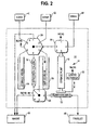
- FIG. 2 is a connection diagram of a separation module that may be used with the system of FIG. 1 ;
- FIG. 3 is a programming screen that may be used with the system of FIG. 1 ;
- FIG. 4 depicts programming steps that may be used with the system of FIG. 1 ;
- FIG. 5 depicts additional programming steps that may be used with the system of FIG. 1 ;
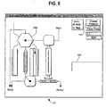
- FIG. 6 depicts operation selection steps that may be used with the system of FIG. 1 ;
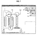
- FIGs. 7-17 depict steps of a separation process that may be provided by the system of FIG. 1 .
- FIG. 1 is a block diagram of a separation system 10, for the separation of radioactive materials, shown generally.
- the system 10 provides for the rapid chromatographic separation of clinically useful quantities of highly pure radioactive materials for use in diagnostic or therapeutic nuclear medicine.
- the separation system 10 may be used to separate a parent radionuclide from a daughter radionuclide where the daughter radionuclide may be produced by decay of the parent. Separation may occur by trapping the parent radionuclide (i.e., using a conventional generator and the forward COW process) or by trapping the daughter radionuclide (i.e., using a selectivity inversion generator and the reverse COW process). While the system 10 will be described in terms of a multicolumn selectivity inversion generator, it is to be understood that either method may be used.
- the system may be fabricated in the form of a lightweight, portable, modular system 10 that is simple to use in radionuclide production facilities, nuclear pharmacies or a medical environment.
- the modular system 10 may include a computer controller (e.g., a laptop computer) 12, a power supply/interface module 13, radioactivity shield 15 and a separation module 14.
- the shield 15 may be of any appropriate material (e.g., glass, plexiglass, plastic, lead, depleted uranium) and may be positioned between the laptop 12 and the separation unit 14 for the protection of the operator (not shown) during the separation process.
- Lightweight shielding e.g., plastic, plexiglass, etc.
- the heavier shielding materials may be used for high energy gamma rays.
- the controller 12 may include a central processing unit (CPU) 18, a keyboard 22 and display 23.
- An internal memory 19 may be provided for the storage and retrieval of separation programs and set points.
- One or more software timers 21 may be provided for controlling the separation process.
- controller 12 will be described in terms of control using the keyboard 22, it should be understood that the keyboard 22 may be replaced by touchscreen technology or other advanced user input device. Accordingly, the controller 12 may include appropriate hardware and software to support a touchscreen interface.
- FIG. 2 is a connection diagram of the processing elements of the separation module 14 of FIG. 1 in more detail.
- the separation module 14 may include a high speed syringe pump 16, multiport valves 24, 26, 28 and a set of chromatographic columns 30, 32 containing one or more materials with high chemical selectivities.
- the separation module 14 may be remotely controlled by the computer system 12 through interface 13.
- the control of the separation module 14 by the computer 12 simplifies operation and enforces strict adherence to approved protocols for radionuclide purification.
- the small size of the separation module 14 simplifies shielding and, when combined with remote operation, the module 14 minimizes radiation exposure to the clinical staff and/or patient.
- the separations chemistry, hardware and software can be readily adapted to meet any of a range of needs of the nuclear medical practitioner.
- the system 10 is particularly well suited for use as a radionuclide generator in that separations can be performed rapidly (e.g., in less than 5 minutes) to yield an ultra-high purity product (e.g., decontamination factors of 10 6 or greater).
- the ultra-high purity of the end product is enhanced by a unique guard column 32 that follows the primary separation column 30.
- Separation columns 30, 32 can be selected for purification of a wide range of radionuclides, depending upon the diagnostic or therapeutic objectives.
- the apparatus has been found to be particularly well suited for the purification of yttrium-90, bismuth-212 and 213, or rhenium-188 for radiotherapy or technetium-99m, thallium-201, fluorine-18 or indium-111 for diagnostic imaging.
- the transport of radionuclides within the system 10 relies upon the syringe pump 16 and multiport valves 24, 26, 28.
- the syringe pump 16 may be any small volume device with a relatively precise volume control (e.g., a model MBP2000 syringe pump provided by Advanced Liquid Handling of Milwaukee, WI).
- the syringe pump 16 may include a syringe body 18 and linear actuator 20.
- the syringe body 18 may be a variable displacement device (e.g., with a maximum capacity of 5 milliliters (ml), 10 ml, etc.).
- the linear actuator 20 may provide a resolution of 2000 steps between a maximum volume state of the syringe body 18 and a zero volume state of the syringe body 18.
- the syringe body 18 may have a maximum volume state of 5 ml.
- any size syringe 18 may be used.
- the step rate at which the controller 12 drives the linear actuator 20 defines the flow rate into or out of the syringe body 18. For example, if the syringe body 18 has a maximum volume of 5 ml and the linear actuator has 2000 positions between maximum and zero volume, then each step of (i.e., actuating pulse applied to) the actuator 20 results in a volume change within the syringe body 18 of 0.0025 ml. At a rate of one pulse per second, the flow rate into or out of the syringe pump 16 would be 0.0025 ml/second. Alternatively, the linear actuator 20 may be driven at a rate of up to 2000 pulses/s resulting in a flow rate of 5 ml/s, or any rate in between.
- the multiport valves may be sized to accommodate expected flow rates from the syringe pump 16.
- Multiport valve A 24 may be any appropriately sized multi-position valve (e.g., a Model 6-5 MVP plug valve, 6 port distribution, by Hamilton Co., Reno, NV) with a common port connected to multiport valve C 26.
- multiport valve B 28 may be an appropriately sized multi-position valve (e.g., a Model 4-5 MVP, plug valve, 4-port distribution by Hamilton Co.) with common port connected to the separation column 30.
- Multiport valve C 26 may be a 4-port special valve supplied as a part of the assembly of the syringe pump 16 (as provided for in the part number given above for the syringe pump 16) or may be supplied as a separate, stand-alone valve assembly.
- Appropriate valve positioners e.g., a Hamilton 'Modular Valve Positioner' (MVP) with digital TTL communications
- MVP Hamilton 'Modular Valve Positioner'
- Additional valve positioners and syringe pumps may be connected to the interface module 13 to provide additional fluid delivery and control capabilities.
- the separation column 30 and guard column 32 may be fabricated as cylindrical structures (e.g., 1.27 cm x 5.08 cm (1/2 inch x 2 inches)) with tubing connections on each end.
- the separation column 30 and guard column 32 may be filled with a chromatographic material (e.g., ion-exchange resin, extraction chromatographic material, etc.) appropriate for the radionuclide to be separated.
- the guard column 32 may include one, two or more discrete segments (three shown in the figures) of separation materials.
- the separation elements 16, 24, 26, 28, 30, 32, 36, 38 and external containers 40, 42, 44, 46, 48 may be connected using an appropriate chemical resistant tubing (e.g., Teflon).
- the tubing and fittings may be provided with a diameter (e.g., 2 mm) intended to reduce the deadspace within the separation module 14.
- the controller 12 may be provided with a graphical user interface (GUI) 17 that provides instantaneous flow diagrams and process parameters on the display 23.
- GUI graphical user interface
- the flow diagrams and process parameters allow an operator to monitor operation of the module 14 without directly viewing the module 14. Monitoring the mechanical operations of the module 14 is important since the operator may not be able to directly view the module 14 during operation because of the radiation that may be emitted by the materials processed within the separation module 14.
- the sequence of valve and pump operations of the separator 14 may be controlled by a customized protocol stored in the memory 19 of the controller 12.
- the operator may use predefined existing protocols or may create a new protocol. To create a new protocol, the operator may click on a specific icon on the display and proceed to manually enter operational parameters directly. Alternatively, a specialized graphical user interface may be provided to allow the operator to create new protocols. As a further alternative, the operator may be prompted to enter identifiers of devices and operational activities.
- a programming screen 100 ( FIG. 3 ) may be presented to the operator.
- the operator may click on a "Create New Protocol" button 104.
- the operator may click on a mode box 106.
- the controller 12 may present the operator with a selection box 110 ( FIG. 4 ) offering the operator a number of possible operations.
- the operator may click on the Withdraw box 112.
- the operator may then click on Valve A, Valve B or Valve C boxes to define values for the positions of the valves 24, 28, 26, respectively, to execute the selected step. Defining values may simply mean entry of a port number shown in FIG. 2 in the box appearing directly below the valve identifier.
- the box 116 may appear offering the operator a number of sources to withdraw material from. Clicking on 'Strip' may automatically program Valves A and C. Alternatively, the operator may click on and program the valves individually.
- the operator may click on a Volume box 102. Following selection of the Volume box 102, the operator may enter a total volume using the keyboard 22. Using the procedure described herein, the operator may create a separation program appropriate to the radionuclide being processed.
- the operator may activate a "Load Existing Protocol" box 120 ( FIG. 5 ).
- the operator may also click on a particular step (e.g., step 4).
- a flow diagram 122 may be presented to the operator displaying the flow provided by the selected step.
- the operator may also edit existing programs. For example, the operator may click on an "Add Step” button 122 to add another process step or a "Remove Step” button 124 to remove a step. Alternatively, the operator may click on an "Insert Step” button 126 to insert another step. Upon completing a protocol, the operator may activate a "Save to File” button to save the protocol and then click on an "Exit” button (128) to close the protocol preparation program.
- the operator may click on a predefined icon located on the display 23.
- the controller 12 may present the operator with a protocol selection screen 130 ( FIG. 6 ).
- the operator may click on a "Choose Protocol" button 132 and enter a protocol identifier in a selection window 134.
- FIGs. 7-17 depict program screens that may be used in a particular separation process. For purposes of explanation, it may be assumed that a parent radionuclide has previously been transferred from an external source (shipping container) 40 to an internal storage vessel 38 ( FIG. 2 ).
- the storage vessel 38 may contain a mixture of parent and daughter radionuclides.
- the program of FIGS. 7-17 may be executed automatically or one step at a time.
- the execution mode may be selected by a selection switch 148.
- the operator may initiate each step by activating the "START" button 146.
- an instantaneous flow diagram ( FIGs. 7-17 ) is presented to the operator showing the process step being executed.
- a cumulative flow indicator 142 and elapsed time indicator 150 or progress bar may be provided for purposes of monitoring a flow rate.
- Step #1 of the process is shown in FIG. 7 .
- the controller 12 has moved Valve A 24 to port #5 ( FIG. 1 ) and Valve C 26 to port #1.
- the fact that the process has not yet started is reflected in the time display 142 which remains at zero.
- Step #1 the selected volume of Step #1 is 2 ml.
- the controller 12 may automatically proceed to the second step ( FIG. 8 ). As shown in FIG. 8 , the second step is loading the separation column 30 with the parent and daughter radionuclide.
- Step #2 the controller 12 has moved Valve A 24 to port #4.
- the position of Valve C 26 has not changed.
- Valve B 28 has been moved to port #1 to discharge into the temporary storage container 36.
- the controller 12 instructs the linear actuator 20 to move a plunger of the syringe body 18 upwards to discharge the parent and daughter radionuclides into the separation column 30.
- the daughter radionuclide may be captured within the resin operating as part of a multicolumn selectivity inversion generator.
- the rate of movement of the plunger may be programmed to accommodate the optimal chromatographic flow rate for use with the separation column 30. In general, a flow rate of 1 ml per second for each square cm of column cross-sectional area (1 ml/min/cm 2 ) may be chosen.
- the controller 12 moves to the third step ( FIG. 9 ).
- the controller 12 has moved Valve C 26 to port #2 to retrieve a wash solution.
- the display shows that 2.000 ml has been delivered through the column 30 and 1 ml is to be loaded as a wash.
- Valve C 26 has been moved back to port #1. In this case, the wash solution is passed though the separation column 30 to wash any remaining parent radionuclides from the column.
- the fifth and sixth steps FIGs. 11 and 12 ). the process is repeated.
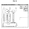
- FIG. 13 shows Step #7.
- a stripping solution is loaded from an external stripping solution container 42.
- the stripping solution used may be specific to the chromatographic material within the separation column 30 and functions to cause the chromatographic material to release the daughter radionuclide.
- Step #8 the stripping solution is directed to a waste container 48. Drawing in and discarding the initial volume of stripping solution in Step #8 functions to wash the syringe body 18 of any remaining parent radionuclides.
- Steps #9 and 10 the stripping solution is again drawn in and then passed through the separation column 30 and guard column 32.
- the guard column 32 functions to remove any remaining parent radionuclide still present in the daughter radionuclide.
- the result passing to the product container 46) is a highly purified solution of the daughter radionuclide.
- the parent radionuclide may be retrieved from the temporary storage container 36 and returned to the storage vessel 38.
- FIGs. 7-17 While the steps of FIGs. 7-17 are shown as occurring in the manual mode, it is to be understood that they may also occur automatically (i.e., each step commencing immediately after conclusion of the preceding step without human intervention). Where performed automatically, the instantaneous flow diagrams shown in FIGs. 7-17 are updated accordingly. A total volume may be displayed along with a relative position of the plunger within the syringe body 18.
- the linear actuator 20 may be operated either open or closed loop. Where controlled in a closed loop fashion, feedback of the plunger position may be used to advance the process from one step to the next. Where performed in an open loop mode, a timer 21 may be used to allow the plunger to advance to a predetermined position before advancing to a following process step.
Landscapes
- Chemical & Material Sciences (AREA)
- Analytical Chemistry (AREA)
- Chemical Kinetics & Catalysis (AREA)
- Physics & Mathematics (AREA)
- Health & Medical Sciences (AREA)
- Life Sciences & Earth Sciences (AREA)
- Biochemistry (AREA)
- General Health & Medical Sciences (AREA)
- General Physics & Mathematics (AREA)
- Immunology (AREA)
- Pathology (AREA)
- Treatment Of Liquids With Adsorbents In General (AREA)
- Medicines Containing Antibodies Or Antigens For Use As Internal Diagnostic Agents (AREA)
- Sampling And Sample Adjustment (AREA)
- Infusion, Injection, And Reservoir Apparatuses (AREA)
- Input Circuits Of Receivers And Coupling Of Receivers And Audio Equipment (AREA)
- Toys (AREA)
- Circuits Of Receivers In General (AREA)
Abstract
Description
- The field of the invention relates to nuclear medicine. More particularly, the invention relates to methods of producing radioactive materials of high radionuclidic and chemical purity for use in nuclear medicine.
- The use of radioactive materials for nuclear medicine is known. Radioactive materials may be used for any of a number of diagnostic and therapeutic purposes. For example, in the case of diagnostic medicine, radioactive materials (i.e., a tracer) may be injected into an arm vein of a patient, and the distribution of the radioactive substance within the body or a part of the body may be portrayed in a series of images. The images may be based upon the emission of gamma rays by the tracer. As the radioactive materials within the tracer decay, the gamma rays may pass out of the body and be recorded by a scintillation camera. The scintillation camera contains a radiation detector that detects the interaction of gamma rays with the detector and where on a face of the detector the interaction has occurred. The interactions may be used to produce a picture or image of where the gamma rays originated from within the body.
- Alternatively, radioactive materials of relatively short half-life (e.g., 2-72 hours) may be used for therapeutic purposes, for example, in the treatment of certain types of tumors (e.g., cancerous tumors). Typically, such materials are coupled to a biolocalization agent that concentrates at the site of the tumor. By localizing the materials at the site of the tumor, the radiation may have a maximum effect on the tumor before natural decay reduces the radiation level or blood circulation carries the material away to other parts of the body.
- Often the radioactive material used for diagnostic or therapeutic purposes is tailored for the application. Where the site has a relatively high circulation rate, a material with a very short half-life may be used. Where the circulation rate is lower a material with a longer half-life may be used.
- While the radioactive materials used in nuclear medicine are very effective, the preparation and handling of such materials has its own difficulties and risks. Because of the short half-lives associated with some materials, they cannot be stored for long periods. Often a material that would have the greatest benefit cannot be used because it cannot be produced in a location convenient for use. Because of the importance of nuclear medicine, a need exists for improved means of providing short half-life radioactive materials of high radionuclidic and chemical purity.
US-A-5368736 discloses a general method for the separation and the purification of Yttrium-90 for medical applications by an extraction chromatographic method. - A method and apparatus are provided for automatically separating radionuclides using an chromatographic separation process. The method includes the steps of displaying a first flow diagram on a display depicting flow of the radionuclides through a first set of separation elements of the plurality of separation processing elements, but only during a first step of the chromatographic separation process and displaying a second flow diagram on the display depicting flow of the radionuclides through a second set of separation elements of the plurality of separation processing elements, but only during a second step of the chromatographic separation process.
-
FIG. 1 is a block diagram of an apparatus for separating radionuclides in accordance with an illustrated embodiment of the invention; -
FIG. 2 is a connection diagram of a separation module that may be used with the system ofFIG. 1 ; -
FIG. 3 is a programming screen that may be used with the system ofFIG. 1 ; -
FIG. 4 depicts programming steps that may be used with the system ofFIG. 1 ; -
FIG. 5 depicts additional programming steps that may be used with the system ofFIG. 1 ; -
FIG. 6 depicts operation selection steps that may be used with the system ofFIG. 1 ; and -
FIGs. 7-17 depict steps of a separation process that may be provided by the system ofFIG. 1 . -
FIG. 1 is a block diagram of aseparation system 10, for the separation of radioactive materials, shown generally. Thesystem 10 provides for the rapid chromatographic separation of clinically useful quantities of highly pure radioactive materials for use in diagnostic or therapeutic nuclear medicine. - The
separation system 10 may be used to separate a parent radionuclide from a daughter radionuclide where the daughter radionuclide may be produced by decay of the parent. Separation may occur by trapping the parent radionuclide (i.e., using a conventional generator and the forward COW process) or by trapping the daughter radionuclide (i.e., using a selectivity inversion generator and the reverse COW process). While thesystem 10 will be described in terms of a multicolumn selectivity inversion generator, it is to be understood that either method may be used. - The system may be fabricated in the form of a lightweight, portable,
modular system 10 that is simple to use in radionuclide production facilities, nuclear pharmacies or a medical environment. Themodular system 10 may include a computer controller (e.g., a laptop computer) 12, a power supply/interface module 13,radioactivity shield 15 and aseparation module 14. Theshield 15 may be of any appropriate material (e.g., glass, plexiglass, plastic, lead, depleted uranium) and may be positioned between thelaptop 12 and theseparation unit 14 for the protection of the operator (not shown) during the separation process. - Lightweight shielding (e.g., plastic, plexiglass, etc.) may be used for separating radionuclides producing low-energy particles (e.g., alpha rays, beta rays, etc.). The heavier shielding materials may be used for high energy gamma rays.
- The
controller 12 may include a central processing unit (CPU) 18, akeyboard 22 anddisplay 23. Aninternal memory 19 may be provided for the storage and retrieval of separation programs and set points. One ormore software timers 21 may be provided for controlling the separation process. - While the
controller 12 will be described in terms of control using thekeyboard 22, it should be understood that thekeyboard 22 may be replaced by touchscreen technology or other advanced user input device. Accordingly, thecontroller 12 may include appropriate hardware and software to support a touchscreen interface. -
FIG. 2 is a connection diagram of the processing elements of theseparation module 14 ofFIG. 1 in more detail. Theseparation module 14 may include a highspeed syringe pump 16,multiport valves chromatographic columns - The
separation module 14 may be remotely controlled by thecomputer system 12 throughinterface 13. The control of theseparation module 14 by thecomputer 12 simplifies operation and enforces strict adherence to approved protocols for radionuclide purification. The small size of theseparation module 14 simplifies shielding and, when combined with remote operation, themodule 14 minimizes radiation exposure to the clinical staff and/or patient. - The separations chemistry, hardware and software can be readily adapted to meet any of a range of needs of the nuclear medical practitioner. For example, the
system 10 is particularly well suited for use as a radionuclide generator in that separations can be performed rapidly (e.g., in less than 5 minutes) to yield an ultra-high purity product (e.g., decontamination factors of 106 or greater). The ultra-high purity of the end product is enhanced by aunique guard column 32 that follows theprimary separation column 30. -
Separation columns - Turning now to the specifics of the
system 10, an explanation will be provided of the hardware and software. Following an explanation of the hardware and software, an example will be provided of the use of thesystem 10. - The transport of radionuclides within the
system 10 relies upon thesyringe pump 16 andmultiport valves syringe pump 16 may be any small volume device with a relatively precise volume control (e.g., a model MBP2000 syringe pump provided by Advanced Liquid Handling of Milwaukee, WI). Thesyringe pump 16 may include asyringe body 18 andlinear actuator 20. Thesyringe body 18 may be a variable displacement device (e.g., with a maximum capacity of 5 milliliters (ml), 10 ml, etc.). - The
linear actuator 20 may provide a resolution of 2000 steps between a maximum volume state of thesyringe body 18 and a zero volume state of thesyringe body 18. For example, under one embodiment thesyringe body 18 may have a maximum volume state of 5 ml. However, anysize syringe 18 may be used. - The step rate at which the
controller 12 drives thelinear actuator 20 defines the flow rate into or out of thesyringe body 18. For example, if thesyringe body 18 has a maximum volume of 5 ml and the linear actuator has 2000 positions between maximum and zero volume, then each step of (i.e., actuating pulse applied to) theactuator 20 results in a volume change within thesyringe body 18 of 0.0025 ml. At a rate of one pulse per second, the flow rate into or out of thesyringe pump 16 would be 0.0025 ml/second. Alternatively, thelinear actuator 20 may be driven at a rate of up to 2000 pulses/s resulting in a flow rate of 5 ml/s, or any rate in between. - The multiport valves may be sized to accommodate expected flow rates from the
syringe pump 16.Multiport valve A 24 may be any appropriately sized multi-position valve (e.g., a Model 6-5 MVP plug valve, 6 port distribution, by Hamilton Co., Reno, NV) with a common port connected tomultiport valve C 26. Similarly,multiport valve B 28 may be an appropriately sized multi-position valve (e.g., a Model 4-5 MVP, plug valve, 4-port distribution by Hamilton Co.) with common port connected to theseparation column 30.Multiport valve C 26 may be a 4-port special valve supplied as a part of the assembly of the syringe pump 16 (as provided for in the part number given above for the syringe pump 16) or may be supplied as a separate, stand-alone valve assembly. Appropriate valve positioners (e.g., a Hamilton 'Modular Valve Positioner' (MVP) with digital TTL communications) may be used as elements of theinterface module 13. Additional valve positioners and syringe pumps may be connected to theinterface module 13 to provide additional fluid delivery and control capabilities. - The
separation column 30 andguard column 32 may be fabricated as cylindrical structures (e.g., 1.27 cm x 5.08 cm (1/2 inch x 2 inches)) with tubing connections on each end. Theseparation column 30 andguard column 32 may be filled with a chromatographic material (e.g., ion-exchange resin, extraction chromatographic material, etc.) appropriate for the radionuclide to be separated. Theguard column 32 may include one, two or more discrete segments (three shown in the figures) of separation materials. - The
separation elements external containers separation module 14. - The
controller 12 may be provided with a graphical user interface (GUI) 17 that provides instantaneous flow diagrams and process parameters on thedisplay 23. The flow diagrams and process parameters allow an operator to monitor operation of themodule 14 without directly viewing themodule 14. Monitoring the mechanical operations of themodule 14 is important since the operator may not be able to directly view themodule 14 during operation because of the radiation that may be emitted by the materials processed within theseparation module 14. - The sequence of valve and pump operations of the
separator 14 may be controlled by a customized protocol stored in thememory 19 of thecontroller 12. The operator may use predefined existing protocols or may create a new protocol. To create a new protocol, the operator may click on a specific icon on the display and proceed to manually enter operational parameters directly. Alternatively, a specialized graphical user interface may be provided to allow the operator to create new protocols. As a further alternative, the operator may be prompted to enter identifiers of devices and operational activities. - Upon startup of the protocol creation software, a programming screen 100 (
FIG. 3 ) may be presented to the operator. To create a new separation program, the operator may click on a "Create New Protocol"button 104. - Next, the operator may click on a
mode box 106. In response, thecontroller 12 may present the operator with a selection box 110 (FIG. 4 ) offering the operator a number of possible operations. The operator may click on the Withdrawbox 112. The operator may then click on Valve A, Valve B or Valve C boxes to define values for the positions of thevalves FIG. 2 in the box appearing directly below the valve identifier. - For example, if after clicking on the Withdraw
box 112 the operator should click on the Valve C box, then thebox 116 may appear offering the operator a number of sources to withdraw material from. Clicking on 'Strip' may automatically program Valves A and C. Alternatively, the operator may click on and program the valves individually. - Following selection of a mode, the operator may click on a
Volume box 102. Following selection of theVolume box 102, the operator may enter a total volume using thekeyboard 22. Using the procedure described herein, the operator may create a separation program appropriate to the radionuclide being processed. - As an alternative to creating a new program, the operator may activate a "Load Existing Protocol" box 120 (
FIG. 5 ). The operator may also click on a particular step (e.g., step 4). In response to selecting a particular step, a flow diagram 122 may be presented to the operator displaying the flow provided by the selected step. - The operator may also edit existing programs. For example, the operator may click on an "Add Step"
button 122 to add another process step or a "Remove Step"button 124 to remove a step. Alternatively, the operator may click on an "Insert Step"button 126 to insert another step. Upon completing a protocol, the operator may activate a "Save to File" button to save the protocol and then click on an "Exit" button (128) to close the protocol preparation program. - To execute a specific protocol, the operator may click on a predefined icon located on the
display 23. In response, thecontroller 12 may present the operator with a protocol selection screen 130 (FIG. 6 ). The operator may click on a "Choose Protocol"button 132 and enter a protocol identifier in aselection window 134. -
FIGs. 7-17 depict program screens that may be used in a particular separation process. For purposes of explanation, it may be assumed that a parent radionuclide has previously been transferred from an external source (shipping container) 40 to an internal storage vessel 38 (FIG. 2 ). - It also may be assumed that sufficient time has passed for some of the parent radionuclide to have decayed into daughter radionuclide. As such, the
storage vessel 38 may contain a mixture of parent and daughter radionuclides. - The program of
FIGS. 7-17 may be executed automatically or one step at a time. The execution mode may be selected by aselection switch 148. - When in manual mode, the operator may initiate each step by activating the "START"
button 146. During each step of the automatic or manual process, an instantaneous flow diagram (FIGs. 7-17 ) is presented to the operator showing the process step being executed. Acumulative flow indicator 142 and elapsedtime indicator 150 or progress bar may be provided for purposes of monitoring a flow rate. -
Step # 1 of the process is shown inFIG. 7 . As shown, thecontroller 12 has movedValve A 24 to port #5 (FIG. 1 ) andValve C 26 toport # 1. The fact that the process has not yet started is reflected in thetime display 142 which remains at zero. - As may be seen the selected volume of
Step # 1 is 2 ml. Once theSTART button 146 is activated, thecontroller 12 may initiate thelinear actuator 20 to draw the parent radionuclide from thestorage container 38. - Once the first step is complete, the
controller 12 may automatically proceed to the second step (FIG. 8 ). As shown inFIG. 8 , the second step is loading theseparation column 30 with the parent and daughter radionuclide. - For
Step # 2, thecontroller 12 has movedValve A 24 toport # 4. The position ofValve C 26 has not changed.Valve B 28 has been moved toport # 1 to discharge into thetemporary storage container 36. - Once the
START button 146 is activated, thecontroller 12 instructs thelinear actuator 20 to move a plunger of thesyringe body 18 upwards to discharge the parent and daughter radionuclides into theseparation column 30. - Within the
separation column 30, the daughter radionuclide may be captured within the resin operating as part of a multicolumn selectivity inversion generator. In order to maximize the efficiency of the process, the rate of movement of the plunger may be programmed to accommodate the optimal chromatographic flow rate for use with theseparation column 30. In general, a flow rate of 1 ml per second for each square cm of column cross-sectional area (1 ml/min/cm2) may be chosen. - Once the second step is complete, the
controller 12 moves to the third step (FIG. 9 ). In this case, thecontroller 12 has movedValve C 26 toport # 2 to retrieve a wash solution. In this case, the display shows that 2.000 ml has been delivered through thecolumn - In the fourth step (
FIG. 10 ),Valve C 26 has been moved back toport # 1. In this case, the wash solution is passed though theseparation column 30 to wash any remaining parent radionuclides from the column. In the fifth and sixth steps (FIGs. 11 and12 ), the process is repeated. -
FIG. 13 shows Step # 7. InStep # 7, a stripping solution is loaded from an external strippingsolution container 42. The stripping solution used may be specific to the chromatographic material within theseparation column 30 and functions to cause the chromatographic material to release the daughter radionuclide. - In
Step # 8, the stripping solution is directed to awaste container 48. Drawing in and discarding the initial volume of stripping solution inStep # 8 functions to wash thesyringe body 18 of any remaining parent radionuclides. - In
Steps # separation column 30 andguard column 32. Theguard column 32 functions to remove any remaining parent radionuclide still present in the daughter radionuclide. The result (passing to the product container 46) is a highly purified solution of the daughter radionuclide. - In
step # 11, the parent radionuclide may be retrieved from thetemporary storage container 36 and returned to thestorage vessel 38. - While the steps of
FIGs. 7-17 are shown as occurring in the manual mode, it is to be understood that they may also occur automatically (i.e., each step commencing immediately after conclusion of the preceding step without human intervention). Where performed automatically, the instantaneous flow diagrams shown inFIGs. 7-17 are updated accordingly. A total volume may be displayed along with a relative position of the plunger within thesyringe body 18. - The
linear actuator 20 may be operated either open or closed loop. Where controlled in a closed loop fashion, feedback of the plunger position may be used to advance the process from one step to the next. Where performed in an open loop mode, atimer 21 may be used to allow the plunger to advance to a predetermined position before advancing to a following process step.
Claims (15)
- A compact apparatus for automatically separating radionuclides using a chromatographic separation process, such apparatus comprising:a plurality of separation processing elements;means for passing radionuclides sequentially through the plurality of separation processing elements;a radioactivity shield disposed around the plurality of separation processing elements;display means located on a protected side of the radioactivity shield;means for causing said display means to display a first flow diagram depicting flow of the radionuclides through a first set of separation elements of the plurality of separation processing elements, but only during a first step of the chromatographic separation process; andmeans for causing said display means to display a second flow diagram depicting flow of the radionuclides through a second set of separation elements of the plurality of separation processing elements, but only during a second step of the chromatographic separation process.
- The apparatus for automatically separating radionuclides as in claim 1 wherein a separation processing element of the plurality of separation processing elements further comprises a separation column containing a chromatographic material.
- The apparatus for automatically separating radionuclides as in claim 2 further comprising means for withdrawing a parent radionuclide from a shipping container.
- The apparatus for automatically separating radionuclides as in claim 3 further comprising means for transferring the parent radionuclide to a second container wherein radioactive decay produces a desired daughter radionuclide.
- The apparatus for automatically separating radionuclides as in claim 4 further comprising means for loading the separation column with the daughter and parent radionuclides.
- The apparatus for automatically separating radionuclides as in claim 5 wherein the means for loading the separation column with the daughter and parent radionuclides further comprises means for passing the parent and daughter radionuclides through the separation column, thereby allowing capture of one of the parent and daughter radionuclides by the separation column.
- The apparatus for automatically separating radionuclides as in claim 6 wherein the means for passing the daughter and parent radionuclides through the separation column further comprises means for routing the radionuclides that have passed through the separation column to a storage container.
- The apparatus for automatically separating radionuclides as in claim 6 further comprising means for withdrawing a wash solution from a vessel containing wash solution.
- The apparatus for automatically separating radionuclides as in claim 8 further comprising means for flushing the separation column with the wash solution to remove any residual parent radionuclides.
- The apparatus for automatically separating radionuclides as in claim 9 further comprising means for withdrawing a strip solution from a vessel containing strip solution.
- The apparatus for automatically separating radionuclides as in claim 10 further comprising means for stripping the daughter radionuclide from the separation column by passing the stripping solution through the separation column.
- The apparatus for automatically separating radionuclides as in claim 11 further comprising means for capturing any remaining traces of the parent radionuclide from the daughter radionuclide using a second column containing one or more chromatographic materials serving as a guard column.
- The apparatus for automatically separating radionuclides as in claim 7 further comprising means for withdrawing the parent radionuclide from the storage container.
- The apparatus for automatically separating radionuclides as in claim 13 further comprising means for returning the parent radionuclide to the growth container for regrowth of daughter radionuclides.
- The apparatus for automatically separating radionuclides as in claim 14 further comprising means for equilibrating the separation column with the solution to be passed through the separation column.
Applications Claiming Priority (3)
| Application Number | Priority Date | Filing Date | Title |
|---|---|---|---|
| US30013401P | 2001-06-22 | 2001-06-22 | |
| US300134P | 2001-06-22 | ||
| PCT/US2002/019609 WO2003000375A1 (en) | 2001-06-22 | 2002-06-21 | Compact automated radionuclide separator |
Publications (3)
| Publication Number | Publication Date |
|---|---|
| EP1404429A1 EP1404429A1 (en) | 2004-04-07 |
| EP1404429A4 EP1404429A4 (en) | 2005-02-02 |
| EP1404429B1 true EP1404429B1 (en) | 2008-09-17 |
Family
ID=23157852
Family Applications (1)
| Application Number | Title | Priority Date | Filing Date |
|---|---|---|---|
| EP02749624A Expired - Lifetime EP1404429B1 (en) | 2001-06-22 | 2002-06-21 | Compact automated radionuclide separator |
Country Status (11)
| Country | Link |
|---|---|
| US (1) | US6770195B2 (en) |
| EP (1) | EP1404429B1 (en) |
| JP (1) | JP4309254B2 (en) |
| CN (1) | CN1306981C (en) |
| AT (1) | ATE408818T1 (en) |
| AU (1) | AU2002320124B2 (en) |
| CA (1) | CA2451154C (en) |
| DE (1) | DE60228960D1 (en) |
| EA (1) | EA005712B1 (en) |
| WO (1) | WO2003000375A1 (en) |
| ZA (1) | ZA200309765B (en) |
Families Citing this family (15)
| Publication number | Priority date | Publication date | Assignee | Title |
|---|---|---|---|---|
| US7087206B2 (en) * | 2002-04-12 | 2006-08-08 | Pg Research Foundation | Multicolumn selectivity inversion generator for production of high purity actinium for use in therapeutic nuclear medicine |
| US6998052B2 (en) * | 2002-04-12 | 2006-02-14 | Pg Research Foundation | Multicolumn selectivity inversion generator for production of ultrapure radionuclides |
| EP1772157A1 (en) * | 2005-10-06 | 2007-04-11 | Karl-Heinz Jansen | Modular assembly and synthesis method for the production of radiopharmaceuticals and nuclides |
| US7402251B2 (en) * | 2005-12-28 | 2008-07-22 | Mann Welding Company | Chromatography column and method of operation |
| KR100742639B1 (en) * | 2006-01-19 | 2007-07-25 | 한국원자력안전기술원 | Multiple automatic simultaneous separation device for radionuclide separation and uranium automatic separation method using the same |
| US7554098B2 (en) * | 2007-04-20 | 2009-06-30 | Battelle Memorial Institute | Medical isotope generator systems |
| MX2010002249A (en) * | 2007-08-31 | 2010-03-17 | Amgen Inc | Solid-state protein formulation. |
| FR2990956B1 (en) * | 2012-05-24 | 2014-07-04 | Areva Med Sas | PROCESS AND APPARATUS FOR THE PRODUCTION OF LEAD 212 FOR MEDICAL USE |
| US9299466B2 (en) * | 2013-10-30 | 2016-03-29 | NorthStar Medical Radioisotopes LLC | System for processing and tracking radionuclides |
| CN104268374B (en) * | 2014-09-09 | 2017-07-28 | 中国核电工程有限公司 | The method for calculating the short-half-life daughter nucleus bank deposit external irradiation dose of Long-lived Radionuclides |
| US20160223205A1 (en) * | 2015-01-30 | 2016-08-04 | Oscar Yonghwan CHOI | Timer device for stove |
| CN106732481B (en) * | 2017-01-10 | 2019-04-05 | 苏州大学 | A kind of pertechnetate adsorbent and its synthesis method and its application in the treatment of radioactive wastewater |
| WO2019183724A1 (en) | 2018-03-26 | 2019-10-03 | Triumf, A Joint Venture Of The Governors Of The University Of Alberta, The University Of British Columbia, The Governors Of The University Of Calgary, Carleton University, University Of Guelph, Mcmaster University, University Of Manitoba, Universite De Montreal, Queen's University, University Of Reg | Systems, apparatus and methods for separating actinium, radium, and thorium |
| CN109521457B (en) * | 2018-09-25 | 2022-10-21 | 中国辐射防护研究院 | Gamma radiation source item partitioning method and system based on information criterion |
| CN116594053B (en) * | 2023-07-18 | 2024-01-19 | 清华大学 | The radioactive solution contains transuranic alpha nuclide, 90 Sr and 137 cs separation system and device |
Family Cites Families (17)
| Publication number | Priority date | Publication date | Assignee | Title |
|---|---|---|---|---|
| JPS59145022A (en) * | 1983-02-08 | 1984-08-20 | Japan Atom Energy Res Inst | Separation of lithium isotope |
| US4762617A (en) * | 1987-01-15 | 1988-08-09 | The United States Of America As Represented By The United States Department Of Energy | Size-exclusion chromatography system for macromolecular interaction analysis |
| US5110474A (en) * | 1990-04-09 | 1992-05-05 | Arch Development Corporation | Method for liquid chromatographic extraction of strontium from acid solutions |
| US5368736A (en) * | 1993-07-26 | 1994-11-29 | The United States Of America As Represented By The United States Department Of Energy | Process for the separation and purification of yttrium-90 for medical applications |
| CA2146177C (en) * | 1995-04-03 | 2000-09-05 | Adrian P. Wade | Intelligent flow analysis network |
| US5774782A (en) * | 1996-05-22 | 1998-06-30 | Lockheed Martin Energy Systems, Inc. | Technetium-99m generator system |
| WO1998008481A2 (en) * | 1996-08-26 | 1998-03-05 | Arch Development Corporation | PROCESS AND APPARATUS FOR THE PRODUCTION OF Bi-212 AND A USE THEREOF |
| US5729821A (en) * | 1996-12-10 | 1998-03-17 | Lockheed Martin Energy Research Coirporation | Concentration of perrhenate and pertechnetate solutions |
| WO1998040395A1 (en) * | 1997-03-14 | 1998-09-17 | Transgenomic, Inc. | Band array display of polynucleotide separations |
| US5854968A (en) * | 1997-06-09 | 1998-12-29 | Arch Development Corporation | Process and apparatus for the production of BI-213 cations |
| WO1999049931A2 (en) * | 1998-03-30 | 1999-10-07 | Sloan-Kettering Institute For Cancer Research | Bismuth-213 generator and uses thereof |
| US6153154A (en) * | 1998-05-27 | 2000-11-28 | Battelle Memorial Institute | Method for sequential injection of liquid samples for radioisotope separations |
| PT967618E (en) * | 1998-06-22 | 2003-12-31 | Europ Economic Community | METHOD AND DEVICE FOR THE PREPARATION OF BI-213 FOR HUMAN THERAPEUTIC USE |
| US6245305B1 (en) * | 1998-11-10 | 2001-06-12 | Battelle Memorial Institute | Method of separating and purifying gadolinium-153 |
| US6157036A (en) * | 1998-12-02 | 2000-12-05 | Cedars-Sinai Medical Center | System and method for automatically eluting and concentrating a radioisotope |
| WO2001046687A2 (en) * | 1999-12-22 | 2001-06-28 | Transgenomic, Inc. | System and method for automated matched ion polynucleotide chromatography |
| ATE527038T1 (en) * | 2001-06-22 | 2011-10-15 | Pg Res Foundation Inc | AUTOMATED SYSTEM AND METHOD FOR SEPARATION OF RADIONUCLIDES |
-
2002
- 2002-06-21 DE DE60228960T patent/DE60228960D1/en not_active Expired - Lifetime
- 2002-06-21 EP EP02749624A patent/EP1404429B1/en not_active Expired - Lifetime
- 2002-06-21 US US10/178,003 patent/US6770195B2/en not_active Expired - Lifetime
- 2002-06-21 CN CNB028125290A patent/CN1306981C/en not_active Expired - Lifetime
- 2002-06-21 WO PCT/US2002/019609 patent/WO2003000375A1/en not_active Ceased
- 2002-06-21 EA EA200301245A patent/EA005712B1/en unknown
- 2002-06-21 AU AU2002320124A patent/AU2002320124B2/en not_active Expired
- 2002-06-21 JP JP2003507015A patent/JP4309254B2/en not_active Expired - Fee Related
- 2002-06-21 AT AT02749624T patent/ATE408818T1/en not_active IP Right Cessation
- 2002-06-21 CA CA2451154A patent/CA2451154C/en not_active Expired - Lifetime
-
2003
- 2003-12-17 ZA ZA200309765A patent/ZA200309765B/en unknown
Also Published As
| Publication number | Publication date |
|---|---|
| CN1518475A (en) | 2004-08-04 |
| EP1404429A1 (en) | 2004-04-07 |
| US20020195391A1 (en) | 2002-12-26 |
| JP4309254B2 (en) | 2009-08-05 |
| EA005712B1 (en) | 2005-04-28 |
| JP2005500517A (en) | 2005-01-06 |
| WO2003000375A1 (en) | 2003-01-03 |
| CN1306981C (en) | 2007-03-28 |
| CA2451154A1 (en) | 2003-01-03 |
| CA2451154C (en) | 2012-02-07 |
| ATE408818T1 (en) | 2008-10-15 |
| EP1404429A4 (en) | 2005-02-02 |
| AU2002320124B2 (en) | 2006-12-14 |
| ZA200309765B (en) | 2004-09-28 |
| DE60228960D1 (en) | 2008-10-30 |
| EA200301245A1 (en) | 2004-06-24 |
| US6770195B2 (en) | 2004-08-03 |
Similar Documents
| Publication | Publication Date | Title |
|---|---|---|
| CA2451154C (en) | Compact automated radionuclide separator | |
| AU2002320124A1 (en) | Compact automated radionuclide separator | |
| US6157036A (en) | System and method for automatically eluting and concentrating a radioisotope | |
| US20030127395A1 (en) | Automated radionuclide separation system and method | |
| KR20090057979A (en) | Medical devices for the collection, calibration, dilution and / or infusion of injectable radioactive material | |
| US20090224171A1 (en) | System and Method for Controlling Elution from a Radioisotope Generator with Electronic Pinch Valves | |
| EP3062840B1 (en) | Product cartridge for radionuclide | |
| US10589250B2 (en) | Automated purification and formulation device for radiopharmaceutical compounds | |
| Lebowitz et al. | Radionuclide generator systems | |
| JP6535336B2 (en) | Radionuclide processing and tracking system | |
| JP4486252B2 (en) | Method and apparatus for continuous injection of liquid sample for radioisotope separation | |
| JP2016500819A (en) | Radioisotope concentrator | |
| Petrik et al. | Radiolabelling of peptides for PET, SPECT and therapeutic applications using a fully automated disposable cassette system | |
| Bray et al. | Development of a unique bismuth (Bi-213) automated generator for use in cancer therapy | |
| Asti et al. | Semiautomated labelling and fractionation of yttrium-90 and lutetium-177 somatostatin analogues using disposable syringes and vials | |
| JP2005230366A (en) | Synthesis and administration apparatus for radioactive pharmaceutical | |
| US20240177880A1 (en) | Terminally sterilized alpha-emitting isotope generator and method for producing terminally sterilized alpha-emitting isotope | |
| EP3840651B1 (en) | 82rb elution system control and configurations | |
| EP0967618A1 (en) | Method and apparatus for preparing Bi-213 for human therapeutic use | |
| Diaz et al. | Development and validation of a semi-automated [13N] Ammonia preparation system for clinical research | |
| CN119548985A (en) | A system and processing method for extracting and separating 228Th after reactor irradiation with 226Ra | |
| Votaw et al. | Automatic, sterile, and apyrogenic delivery of PET radiotracers from the cyclotron to the patient | |
| CN117594277A (en) | Enrichment from reactor irradiation 46 Extracting Ca target material 47 Sc device and method | |
| Bond et al. | A compact automated radionuclide separation system for nuclear medical applications | |
| Yano | Essentials of a Rubidium-82 generator for nuclear medicine |
Legal Events
| Date | Code | Title | Description |
|---|---|---|---|
| PUAI | Public reference made under article 153(3) epc to a published international application that has entered the european phase |
Free format text: ORIGINAL CODE: 0009012 |
|
| 17P | Request for examination filed |
Effective date: 20031219 |
|
| AK | Designated contracting states |
Kind code of ref document: A1 Designated state(s): AT BE CH CY DE DK ES FI FR GB GR IE IT LI LU MC NL PT SE TR |
|
| AX | Request for extension of the european patent |
Extension state: AL LT LV MK RO SI |
|
| RIC1 | Information provided on ipc code assigned before grant |
Ipc: 7B 01D 15/08 B Ipc: 7G 01N 30/88 A |
|
| A4 | Supplementary search report drawn up and despatched |
Effective date: 20041217 |
|
| 17Q | First examination report despatched |
Effective date: 20050908 |
|
| GRAP | Despatch of communication of intention to grant a patent |
Free format text: ORIGINAL CODE: EPIDOSNIGR1 |
|
| GRAS | Grant fee paid |
Free format text: ORIGINAL CODE: EPIDOSNIGR3 |
|
| GRAA | (expected) grant |
Free format text: ORIGINAL CODE: 0009210 |
|
| AK | Designated contracting states |
Kind code of ref document: B1 Designated state(s): AT BE CH CY DE DK ES FI FR GB GR IE IT LI LU MC NL PT SE TR |
|
| REG | Reference to a national code |
Ref country code: GB Ref legal event code: FG4D |
|
| REG | Reference to a national code |
Ref country code: CH Ref legal event code: EP |
|
| REG | Reference to a national code |
Ref country code: IE Ref legal event code: FG4D |
|
| REF | Corresponds to: |
Ref document number: 60228960 Country of ref document: DE Date of ref document: 20081030 Kind code of ref document: P |
|
| PG25 | Lapsed in a contracting state [announced via postgrant information from national office to epo] |
Ref country code: FI Free format text: LAPSE BECAUSE OF FAILURE TO SUBMIT A TRANSLATION OF THE DESCRIPTION OR TO PAY THE FEE WITHIN THE PRESCRIBED TIME-LIMIT Effective date: 20080917 Ref country code: AT Free format text: LAPSE BECAUSE OF FAILURE TO SUBMIT A TRANSLATION OF THE DESCRIPTION OR TO PAY THE FEE WITHIN THE PRESCRIBED TIME-LIMIT Effective date: 20080917 |
|
| NLV1 | Nl: lapsed or annulled due to failure to fulfill the requirements of art. 29p and 29m of the patents act | ||
| PG25 | Lapsed in a contracting state [announced via postgrant information from national office to epo] |
Ref country code: BE Free format text: LAPSE BECAUSE OF FAILURE TO SUBMIT A TRANSLATION OF THE DESCRIPTION OR TO PAY THE FEE WITHIN THE PRESCRIBED TIME-LIMIT Effective date: 20080917 |
|
| PG25 | Lapsed in a contracting state [announced via postgrant information from national office to epo] |
Ref country code: ES Free format text: LAPSE BECAUSE OF FAILURE TO SUBMIT A TRANSLATION OF THE DESCRIPTION OR TO PAY THE FEE WITHIN THE PRESCRIBED TIME-LIMIT Effective date: 20081228 |
|
| PG25 | Lapsed in a contracting state [announced via postgrant information from national office to epo] |
Ref country code: PT Free format text: LAPSE BECAUSE OF FAILURE TO SUBMIT A TRANSLATION OF THE DESCRIPTION OR TO PAY THE FEE WITHIN THE PRESCRIBED TIME-LIMIT Effective date: 20090217 Ref country code: NL Free format text: LAPSE BECAUSE OF FAILURE TO SUBMIT A TRANSLATION OF THE DESCRIPTION OR TO PAY THE FEE WITHIN THE PRESCRIBED TIME-LIMIT Effective date: 20080917 |
|
| PLBE | No opposition filed within time limit |
Free format text: ORIGINAL CODE: 0009261 |
|
| STAA | Information on the status of an ep patent application or granted ep patent |
Free format text: STATUS: NO OPPOSITION FILED WITHIN TIME LIMIT |
|
| PG25 | Lapsed in a contracting state [announced via postgrant information from national office to epo] |
Ref country code: DK Free format text: LAPSE BECAUSE OF FAILURE TO SUBMIT A TRANSLATION OF THE DESCRIPTION OR TO PAY THE FEE WITHIN THE PRESCRIBED TIME-LIMIT Effective date: 20080917 |
|
| 26N | No opposition filed |
Effective date: 20090618 |
|
| PG25 | Lapsed in a contracting state [announced via postgrant information from national office to epo] |
Ref country code: MC Free format text: LAPSE BECAUSE OF NON-PAYMENT OF DUE FEES Effective date: 20090630 Ref country code: SE Free format text: LAPSE BECAUSE OF FAILURE TO SUBMIT A TRANSLATION OF THE DESCRIPTION OR TO PAY THE FEE WITHIN THE PRESCRIBED TIME-LIMIT Effective date: 20081217 |
|
| REG | Reference to a national code |
Ref country code: CH Ref legal event code: PL |
|
| REG | Reference to a national code |
Ref country code: IE Ref legal event code: MM4A |
|
| PG25 | Lapsed in a contracting state [announced via postgrant information from national office to epo] |
Ref country code: IE Free format text: LAPSE BECAUSE OF NON-PAYMENT OF DUE FEES Effective date: 20090621 Ref country code: CH Free format text: LAPSE BECAUSE OF NON-PAYMENT OF DUE FEES Effective date: 20090630 Ref country code: LI Free format text: LAPSE BECAUSE OF NON-PAYMENT OF DUE FEES Effective date: 20090630 |
|
| PG25 | Lapsed in a contracting state [announced via postgrant information from national office to epo] |
Ref country code: GR Free format text: LAPSE BECAUSE OF FAILURE TO SUBMIT A TRANSLATION OF THE DESCRIPTION OR TO PAY THE FEE WITHIN THE PRESCRIBED TIME-LIMIT Effective date: 20081218 |
|
| PG25 | Lapsed in a contracting state [announced via postgrant information from national office to epo] |
Ref country code: LU Free format text: LAPSE BECAUSE OF NON-PAYMENT OF DUE FEES Effective date: 20090621 |
|
| PG25 | Lapsed in a contracting state [announced via postgrant information from national office to epo] |
Ref country code: TR Free format text: LAPSE BECAUSE OF FAILURE TO SUBMIT A TRANSLATION OF THE DESCRIPTION OR TO PAY THE FEE WITHIN THE PRESCRIBED TIME-LIMIT Effective date: 20080917 |
|
| PG25 | Lapsed in a contracting state [announced via postgrant information from national office to epo] |
Ref country code: CY Free format text: LAPSE BECAUSE OF FAILURE TO SUBMIT A TRANSLATION OF THE DESCRIPTION OR TO PAY THE FEE WITHIN THE PRESCRIBED TIME-LIMIT Effective date: 20080917 |
|
| REG | Reference to a national code |
Ref country code: FR Ref legal event code: PLFP Year of fee payment: 15 |
|
| REG | Reference to a national code |
Ref country code: FR Ref legal event code: PLFP Year of fee payment: 16 |
|
| REG | Reference to a national code |
Ref country code: FR Ref legal event code: PLFP Year of fee payment: 17 |
|
| PGFP | Annual fee paid to national office [announced via postgrant information from national office to epo] |
Ref country code: IT Payment date: 20210511 Year of fee payment: 20 Ref country code: FR Payment date: 20210513 Year of fee payment: 20 Ref country code: DE Payment date: 20210525 Year of fee payment: 20 |
|
| PGFP | Annual fee paid to national office [announced via postgrant information from national office to epo] |
Ref country code: GB Payment date: 20210526 Year of fee payment: 20 |
|
| REG | Reference to a national code |
Ref country code: DE Ref legal event code: R071 Ref document number: 60228960 Country of ref document: DE |
|
| REG | Reference to a national code |
Ref country code: GB Ref legal event code: PE20 Expiry date: 20220620 |
|
| PG25 | Lapsed in a contracting state [announced via postgrant information from national office to epo] |
Ref country code: GB Free format text: LAPSE BECAUSE OF EXPIRATION OF PROTECTION Effective date: 20220620 |