EP1404048A1 - Signalling mechanisms in MIMO HARQ schemes for wireless communication systems - Google Patents
Signalling mechanisms in MIMO HARQ schemes for wireless communication systems Download PDFInfo
- Publication number
- EP1404048A1 EP1404048A1 EP20030255072 EP03255072A EP1404048A1 EP 1404048 A1 EP1404048 A1 EP 1404048A1 EP 20030255072 EP20030255072 EP 20030255072 EP 03255072 A EP03255072 A EP 03255072A EP 1404048 A1 EP1404048 A1 EP 1404048A1
- Authority
- EP
- European Patent Office
- Prior art keywords
- information
- channels
- signaling
- communication system
- communication
- Prior art date
- Legal status (The legal status is an assumption and is not a legal conclusion. Google has not performed a legal analysis and makes no representation as to the accuracy of the status listed.)
- Granted
Links
Images


Classifications
-
- H—ELECTRICITY
- H04—ELECTRIC COMMUNICATION TECHNIQUE
- H04B—TRANSMISSION
- H04B7/00—Radio transmission systems, i.e. using radiation field
- H04B7/02—Diversity systems; Multi-antenna system, i.e. transmission or reception using multiple antennas
- H04B7/04—Diversity systems; Multi-antenna system, i.e. transmission or reception using multiple antennas using two or more spaced independent antennas
- H04B7/0413—MIMO systems
-
- H—ELECTRICITY
- H04—ELECTRIC COMMUNICATION TECHNIQUE
- H04L—TRANSMISSION OF DIGITAL INFORMATION, e.g. TELEGRAPHIC COMMUNICATION
- H04L1/00—Arrangements for detecting or preventing errors in the information received
- H04L1/12—Arrangements for detecting or preventing errors in the information received by using return channel
- H04L1/16—Arrangements for detecting or preventing errors in the information received by using return channel in which the return channel carries supervisory signals, e.g. repetition request signals
- H04L1/18—Automatic repetition systems, e.g. Van Duuren systems
- H04L1/1867—Arrangements specially adapted for the transmitter end
-
- H—ELECTRICITY
- H04—ELECTRIC COMMUNICATION TECHNIQUE
- H04B—TRANSMISSION
- H04B7/00—Radio transmission systems, i.e. using radiation field
- H04B7/02—Diversity systems; Multi-antenna system, i.e. transmission or reception using multiple antennas
- H04B7/04—Diversity systems; Multi-antenna system, i.e. transmission or reception using multiple antennas using two or more spaced independent antennas
- H04B7/06—Diversity systems; Multi-antenna system, i.e. transmission or reception using multiple antennas using two or more spaced independent antennas at the transmitting station
- H04B7/0602—Diversity systems; Multi-antenna system, i.e. transmission or reception using multiple antennas using two or more spaced independent antennas at the transmitting station using antenna switching
-
- H—ELECTRICITY
- H04—ELECTRIC COMMUNICATION TECHNIQUE
- H04B—TRANSMISSION
- H04B7/00—Radio transmission systems, i.e. using radiation field
- H04B7/02—Diversity systems; Multi-antenna system, i.e. transmission or reception using multiple antennas
- H04B7/04—Diversity systems; Multi-antenna system, i.e. transmission or reception using multiple antennas using two or more spaced independent antennas
- H04B7/06—Diversity systems; Multi-antenna system, i.e. transmission or reception using multiple antennas using two or more spaced independent antennas at the transmitting station
- H04B7/0602—Diversity systems; Multi-antenna system, i.e. transmission or reception using multiple antennas using two or more spaced independent antennas at the transmitting station using antenna switching
- H04B7/0608—Antenna selection according to transmission parameters
- H04B7/061—Antenna selection according to transmission parameters using feedback from receiving side
-
- H—ELECTRICITY
- H04—ELECTRIC COMMUNICATION TECHNIQUE
- H04L—TRANSMISSION OF DIGITAL INFORMATION, e.g. TELEGRAPHIC COMMUNICATION
- H04L1/00—Arrangements for detecting or preventing errors in the information received
- H04L1/12—Arrangements for detecting or preventing errors in the information received by using return channel
- H04L1/16—Arrangements for detecting or preventing errors in the information received by using return channel in which the return channel carries supervisory signals, e.g. repetition request signals
- H04L1/18—Automatic repetition systems, e.g. Van Duuren systems
- H04L1/1812—Hybrid protocols; Hybrid automatic repeat request [HARQ]
-
- H—ELECTRICITY
- H04—ELECTRIC COMMUNICATION TECHNIQUE
- H04L—TRANSMISSION OF DIGITAL INFORMATION, e.g. TELEGRAPHIC COMMUNICATION
- H04L1/00—Arrangements for detecting or preventing errors in the information received
- H04L1/12—Arrangements for detecting or preventing errors in the information received by using return channel
- H04L1/16—Arrangements for detecting or preventing errors in the information received by using return channel in which the return channel carries supervisory signals, e.g. repetition request signals
- H04L1/18—Automatic repetition systems, e.g. Van Duuren systems
- H04L1/1812—Hybrid protocols; Hybrid automatic repeat request [HARQ]
- H04L1/1816—Hybrid protocols; Hybrid automatic repeat request [HARQ] with retransmission of the same, encoded, message
-
- H—ELECTRICITY
- H04—ELECTRIC COMMUNICATION TECHNIQUE
- H04L—TRANSMISSION OF DIGITAL INFORMATION, e.g. TELEGRAPHIC COMMUNICATION
- H04L1/00—Arrangements for detecting or preventing errors in the information received
- H04L2001/0092—Error control systems characterised by the topology of the transmission link
-
- H—ELECTRICITY
- H04—ELECTRIC COMMUNICATION TECHNIQUE
- H04L—TRANSMISSION OF DIGITAL INFORMATION, e.g. TELEGRAPHIC COMMUNICATION
- H04L1/00—Arrangements for detecting or preventing errors in the information received
- H04L2001/0092—Error control systems characterised by the topology of the transmission link
- H04L2001/0096—Channel splitting in point-to-point links
Definitions
- the present invention relates to wireless communication systems.
- Communication technology is in a constant state of flux with improvements being made in virtually all aspects of this technology.
- wireless communication systems are being designed, built and upgraded to meet ever the increasing demands of their subscribers.
- One important aspect of wireless communication systems that is currently being upgraded is the capacity ⁇ or more importantly, the throughput--of a wireless communication system.
- Another important and related aspect of the communication system is a system's ability to convey (i.e., transmit and/or receive) information representing not only voice but also data (e.g., graphics, text, digital video).
- a service provider wants to provide both voice and data or the service provider wants a system with greater capacity the system throughput has to be improved. It should be well understood that system throughput is the amount of information transmitted and received successfully (without any errors or with an acceptable amount of errors) by system equipment.
- the system equipment are the various signal transmitting, signal receiving and signal processing equipment typically used in a wireless communication system.
- Examples of system equipment include modulators, encoding circuitry, power amplifiers, decoding circuitry, computers, filters and demodulators.
- a service provider is typically a commercial entity that owns, operates, controls and manages the system equipment.
- System equipment convey information to other system equipment or to user equipment.
- Examples of user equipment include cellular phones, pagers, wireless PCs and Personal Digital Assistants (PDAs).
- PDAs Personal Digital Assistants
- the terms "user” and “user equipment” will hereinafter be used interchangeably.
- In wireless cellular communication systems much of the system equipment is located in base stations that are serving different cells of the communication system.
- a cell is a geographical area defined by physical boundaries.
- a base station is formed from one or more locations within a cell and contains system equipment.
- MIMO Multiple Input Multiple Output
- BLAST Bell Laboratories Layer Space Time
- SISO Single Input Single Output
- a protocol is a set of rules for conveying signaling and traffic information over communication channels of a communication system.
- the protocol is usually part of a standard that is established by standards bodies, industry groups and/or governmental regulatory bodies. SISO systems use one antenna or a one- antenna system to convey information.
- Communication signals conveyed between a system antenna and a user of the communication system are transmitted and/or received over communication channels commonly referred to as traffic channels.
- traffic channels Associated with each traffic channel are signaling channels (also referred to as control channels) which are used to control the flow of information through the traffic channels in accordance with a protocol that is part of an established standard with which the communication system complies.
- the information conveyed over the signaling channels are signaling information which control how communications are initiated, maintained and terminated in the traffic channels.
- Information (signaling and/or traffic) transmitted from system equipment (e.g., base station) to user equipment are said to be transmitted over a forward link.
- information transmitted from user equipment to system equipment are said to be transmitted over a reverse link.
- forward signaling information are transmitted from base station to user equipment and reverse signaling information are transmitted from user equipment to base stations.
- the format of the signaling information transmitted over the forward and reverse links is governed by the standard being followed by the communication system.
- the format of information (signaling and/or traffic) is the particular arrangement of the various portions of that information.
- a block of signaling information conveyed over a signaling channel relates in some manner to a corresponding one or more blocks of traffic information being conveyed over a traffic channel.
- the block of signaling information dictates how information flowing through the traffic channel is to be conveyed, processed and interpreted.
- CDMA Code Division Multiple Access
- 1x-EVDV EVolution for Data and Voice
- SPDCCH Secondary Packet Data Control Channel
- the SPDCCH has a certain format whereby various portions of the signaling information represent how traffic information is to be interpreted and processed.
- SPDCCH In a particular version of SPDCCH for example, there are three (3) bits of information called the Encoder Packet Size (EPS) which indicates the number of bits contained in a block of traffic information being conveyed over a traffic channel.
- the SPDCCH also contains 6 bits called the MAC ID (Medium Access Control IDentifier) which is a particular number that identifies the specific user equipment or mobile conveying the traffic information.
- the SPDCCH further contains a certain number of bits (usually two (2) bits) called the Redundancy Version (RV) bits which indicate the number of times the same block of traffic information has been retransmitted.
- RV Redundancy Version
- the mobile If the mobile received the information without errors, it transmits an ACKnowledge (ACK) confirmation message. If the mobile received the information with errors or with an unacceptable amount of errors, it transmits back a Negative ACKnowledgement (NACK) message to the base station informing the base station that the information was received with errors. The base station retransmits the traffic information upon reception of a NACK confirmation message.
- ACK ACKnowledge
- NACK Negative ACKnowledgement
- the NACK and ACK messages are transmitted over a reverse link channel called the Reverse ACKnowledgement Channel (RACKCH).
- RACKCH Reverse ACKnowledgement Channel
- the base station cannot transmit subsequent traffic information until it receives an ACK or a NACK message from the user equipment. While the base station waits for a confirmation message, it can use that idle time to transmit traffic information to the same user equipment or to other user equipment on a separate channel; in this manner, the base station uses what would otherwise be an idle time period to transmit additional traffic information over other communication channels.
- the various blocks of traffic information transmitted while waiting for a confirmation message have corresponding ACK or NACK messages associated with them.
- Two (2) HARQ (Hybrid Automatic repeat ReQuest) bits are currently used to describe the number of communication channels used in transmitting traffic information from the base station to a user equipment; that is, the base station can have up to four (4) traffic information transmissions to one or more users when taking advantage of the idle period that occurs while waiting for confirmation messages.
- RCQICH Reverse Channel Quality Indicator Channel
- SNR Signal to Noise Ratio
- the present invention provides a method of conveying signaling information over forward and reverse links of a communication system having MIMO antenna systems.
- the signaling information conveyed over the signaling channels are formatted such that they allow relatively larger amounts of signaling information to be conveyed therefore enabling relatively larger amounts of traffic information to be conveyed by the MIMO antenna systems.
- relatively larger amounts of signaling information can be conveyed to provide for the transmission and/or reception of the traffic information.
- the format of the forward link signaling channels provides an arrangement where system equipment are able to switch between antenna elements of a MIMO antenna system to improve the throughput of the communication system.
- the format of the reverse link signaling channels can be modified in any one of three basic ways: (1) reverse link signaling information are time division multiplexed; (2) additional channels are provided for the reverse link signaling information and (3) reverse link information are modulated at relatively higher order modulation. Further, available signaling and traffic communication channels are assigned ⁇ using channel assignment information in the forward link-- to specific users who convey information using a MIMO antenna system.
- the present invention provides a method of conveying signaling information over forward and reverse links of a communication system having MIMO antenna systems.
- the signaling information conveyed over the signaling channels are formatted such that they allow relatively larger amounts of information to be conveyed by MIMO antenna systems.
- MIMO antennas systems relatively larger amounts of signaling information can be conveyed to provide for the transmission and/or reception of the traffic information.
- the format of the forward link signaling channels provides an arrangement where system equipment are able to use antenna elements effectively of a MIMO antenna system to improve the throughput of the communication system.
- the format of the reverse link signaling channels can be modified in any one of three basic ways: (1) reverse link signaling information are time division multiplexed; (2) additional channels are provided for the reverse link signaling information and (3) reverse link information are modulated at relatively higher order modulation. Further, exclusive portions of available signaling and traffic communication channels are assigned to different users who convey information using a MIMO antenna system. Channel assignment information is included in the forward link signaling information to assign available channels (traffic and/or signaling) to particular users. One or more channels can be assigned to a particular user.
- the method of the present invention will be described in the context of a CDMA communication system using a 2x2 MIMO antenna system (two transmit antennas, two receive antennas (not shown)) whose forward link signaling channel is the SPDCCH and whose reverse link signaling channels are the RACKCH and the RCQICH.
- CRC Cyclic Redundancy Check
- Channel coding comprises various well known channel coding operations in which bits are added to a block of information to add redundancy to the information thereby making the coded block more robust and less vulnerable to channel anomalies that cause errors to occur.
- a portion of the channel coded information and error correction coded information is applied to modulator 106 and transmitted by antenna element 110. Another portion of the information is applied to modulator 108 and transmitted by antenna element 112.
- the apportionment of the information to be transmitted can be performed at any point along the CRC, encoder, modulator and antenna system architecture. Also, the apportionment can occur prior to the traffic information being applied to the CRC coder.
- FIG. 2 a transmit system equipment architecture similar to that shown in FIG.
- FIG. 1 is shown except that the apportionment of the information to be transmitted is done at the Encoder. Unlike FIG. 1, in FIG. 2 there are two channel encoders (204, 210) connected to modulators 206 and 212 respectively. The modulators are connected to antenna elements 208 and 214 respectively. CRC coder 202, which is connected to the input of both channel encoders (204, 210), applies the proper CRC coding to the information that is to be transmitted.
- portions of the traffic information are transmitted by different antennas, all of the transmitted portions are to be received without errors; otherwise the original block of traffic information cannot be decoded. Therefore, when at least one of the portions is received with errors, the entire block of traffic information has to be retransmitted.
- the traffic information is divided into two portions (a first portion and a second portion) and one of the portions is received with errors. Because the decoding is performed on the entire block of traffic information it is not possible to determine which of the channels and corresponding antenna transmitted the erroneous portion. It may be that one of the antennas and its corresponding channel is causing the errors.
- the method of the present invention allows the traffic information to be retransmitted using different antennas by adding a "swapping" signaling information to the format of the SPDCCH.
- Swapping signaling information is information that indicate which system equipment is to be used to transmit the forward link traffic information.
- the swapping information e.g., swapping bits
- the traffic information can be retransmitted whereby the second portion is now transmitted by antenna element 208 and the first portion is transmitted by antenna element 214.
- both portions can be retransmitted by either antenna element 208 or antenna element 214.
- the traffic information can be retransmitted using the same antennas for the same portions.
- the value of the swapping bit information determines which antenna elements transmit which portions of the traffic information. The swapping information thus allows the communication system to select which antenna element is to retransmit traffic information.
- the method of the present invention provides three basic mechanisms to convey these signaling information.
- a Time Division Multiplex (TDM) technique can be used to transmit these signaling information from user equipment to system equipment.
- the service provider will assign particular time slots to particular user equipment to allow each such user equipment to transmit signaling information over the reverse link at their designated time slots.
- the time slots are 1.25 msec in duration.
- a second mechanism provided by the method of the present invention for the reverse link signaling channels is the addition of communication channels.
- the system is modified to have 128-ary (i.e., 7-bit) Walsh codes.
- Walsh codes are a set of N-bit codes (each of which is unique within the set) that do not interfere with each other even when transmitted simultaneously with attached signaling and/or traffic information; N is an integer equal to 2 or greater.
- each Walsh code is akin to a separate and independent communication channel.
- the third mechanism provided by the method of the present invention is to allow the reverse link information to be transmitted at relatively higher order modulation.
- the modulation order refers to the amount of information represented by a transmitted symbol.
- the reverse link information is transmitted using BPSK (Binary Phase Shift Keying) where a transmitted symbol represents one bit of information.
- the reverse link signaling information is transmitted using QPSK (Quadrature Phase Shift Keying) where a transmitted symbol represents two bits of information.
- QPSK Quadratture Phase Shift Keying
- the Signal to Interference Noise Ratio (SINR) of signals conveyed over forward traffic channels are transmitted by users to system equipment over the RCQICH.
- the system defines a threshold power level and the user equipment measure the power levels of the signals transmitted over the traffic channels.
- the measured power levels and the defined threshold power levels are used by the user equipment to calculate the SINR for a particular traffic channel.
- FIG. 3 there is shown a typical transmit system equipment architecture where information to be transmitted are CRC coded by different CRC coders (302, 312).
- the channel encoders (304, 314), modulators (306, 316) and antenna elements (308, 318) are separate distinct system transmit equipment.
- the term "branch” refers to one set of transmit equipment such as CRC 302, Encoder 304, Modulator 306 and antenna 308 (hereinafter "the first branch").
- Another set of transmit equipment i.e., another "branch," is represented by CRC 312, Encoder 314, Modulator 316 and antenna 318 (hereinafter “the second branch").
- the second branch is represented by CRC 312, Encoder 314, Modulator 316 and antenna 318.
- the first block of information is transmitted using the first branch while at the same time a second block of information is transmitted using the second branch.
- each block of information has a different CRC. That is, the first block is coded by CRC 302 while the second block is coded by CRC 312.
- the transmit equipment Because the blocks have different CRCs, there is greater flexibility afforded the transmit equipment because it does not have to retransmit both blocks of information in the case one of the blocks was received with errors; the equipment can retransmit only the block that was received with errors. Alternatively, the transmit equipment can retransmit the block by itself or retransmit the block simultaneously with a new block of information. This flexibility allows a service provider to increase a system's s throughput because it does not have to retransmit information that has already been received correctly (i.e., without errors).
- portions of the set of communication channels (signaling and traffic channels) of the communication system are assigned to specific users.
- certain users will have certain forward and reverse link signaling channels associated with them.
- the system equipment will indicate the particular communication channels assigned to particular users with channel assignment information included in the forward link signaling channel (e.g., SPDCCH); that is, channel assignment information is signaling information that indicates which particular channels of a communication system are assigned to which users. More than one channel can be assigned to a particular user.
- Signaling information containing assigned set of communication channels are broadcast to intended users, but such signaling information are received and decoded by unintended users so that the users can determine their assigned portions of the available communication channels.
- Walsh code space 400 of available set of codes is shown.
- the code space is being apportioned between three users where each portion is delineated by boundaries.
- user 1 is assigned the set of codes bounded by T 1
- user 2 is bounded by T 1 and T 2
- user 3 is bounded by T 2 and T 3 .
- Information transmitted by system equipment over an SPDCCH contains the boundary information (i.e., a type of channel assignment information) indicating that T 1 is the boundary for user 1. This information is broadcast by the transmit equipment and is thus not only received and decoded by user 1, but is also received and decoded by users 2 and 3.
- signaling information over an SPDCCH intended for user 2 contains the boundary information T 2 and signaling information transmitted over the SPDCCH intended for user 3 contains boundary information T 3 .
- User 1 then is able to determine that all codes above boundary T 1 are available for use.
- User 2 is able to determine that all codes above boundary T 2 but below boundary T 1 are available for use.
- User 3 is able to determine that all codes above boundary T 3 but below boundary T 2 are available for use.
- each user is able to determine its portion of available codes from the reception and decoding of signaling information intended for that user and signaling information intended for other users. For example, user 2 was able to determine its available code portion from its received signaling information and signaling information intended for user 1.
- user 3 uses its own received signaling boundary information and signaling boundary information intended for user 2 to determine its available code portion. Therefore, in general, a user equipment is able to determine its set of available channels from signaling information it receives and from signaling information intended for other user equipment.
- the channel assignment information is called signaling boundary information for CDMA systems because such systems, as explained earlier, represent their channels with Walsh codes.
- the method of the present invention is applicable to other types of wireless communication systems and is not limited to the CDMA communication system discussed above. Further, the method of the present invention is also applicable to wireline communication systems.
Landscapes
- Engineering & Computer Science (AREA)
- Computer Networks & Wireless Communication (AREA)
- Signal Processing (AREA)
- Mobile Radio Communication Systems (AREA)
- Radio Transmission System (AREA)
Abstract
Description
- The present invention relates to wireless communication systems.
- Communication technology is in a constant state of flux with improvements being made in virtually all aspects of this technology. In particular, wireless communication systems are being designed, built and upgraded to meet ever the increasing demands of their subscribers. One important aspect of wireless communication systems that is currently being upgraded is the capacity―or more importantly, the throughput--of a wireless communication system. Another important and related aspect of the communication system is a system's ability to convey (i.e., transmit and/or receive) information representing not only voice but also data (e.g., graphics, text, digital video). Whether a service provider wants to provide both voice and data or the service provider wants a system with greater capacity, the system throughput has to be improved. It should be well understood that system throughput is the amount of information transmitted and received successfully (without any errors or with an acceptable amount of errors) by system equipment.
- The system equipment are the various signal transmitting, signal receiving and signal processing equipment typically used in a wireless communication system. Examples of system equipment include modulators, encoding circuitry, power amplifiers, decoding circuitry, computers, filters and demodulators. A service provider is typically a commercial entity that owns, operates, controls and manages the system equipment. System equipment convey information to other system equipment or to user equipment. Examples of user equipment include cellular phones, pagers, wireless PCs and Personal Digital Assistants (PDAs). The terms "user" and "user equipment" will hereinafter be used interchangeably. In wireless cellular communication systems much of the system equipment is located in base stations that are serving different cells of the communication system. A cell is a geographical area defined by physical boundaries. A base station is formed from one or more locations within a cell and contains system equipment.
- One of the critical components of a wireless communication system that directly affects a communication system's capacity and throughput is the antenna equipment used in the system. Antennas transmit and receive communication signals that carry various types of information (e.g., voice, data) throughout the communication channels of the communication system. In order to increase a communication system's capacity and throughput, the number of the antennas themselves has to increase. One technique used for increasing the capacity of antennas is to use a Multiple Input Multiple Output (MIMO) antenna system whereby an array of antenna elements is used to simultaneously transmit and receive communication signals. One example of a MIMO system is the Bell Laboratories Layer Space Time (BLAST) system developed by Bell Labs of Lucent Technologies, headquartered in Murray Hill, New Jersey. Current antenna systems typically used in wireless communication systems employ a single antenna for a transmitter and a single antenna for a receiver are known as Single Input Single Output (SISO) systems that transmit and/or receive communication signals as per a protocol that is part of an established standard. A protocol is a set of rules for conveying signaling and traffic information over communication channels of a communication system. The protocol is usually part of a standard that is established by standards bodies, industry groups and/or governmental regulatory bodies. SISO systems use one antenna or a one- antenna system to convey information.
- Communication signals conveyed between a system antenna and a user of the communication system are transmitted and/or received over communication channels commonly referred to as traffic channels. Associated with each traffic channel are signaling channels (also referred to as control channels) which are used to control the flow of information through the traffic channels in accordance with a protocol that is part of an established standard with which the communication system complies. The information conveyed over the signaling channels are signaling information which control how communications are initiated, maintained and terminated in the traffic channels. Information (signaling and/or traffic) transmitted from system equipment (e.g., base station) to user equipment are said to be transmitted over a forward link. Conversely, information transmitted from user equipment to system equipment are said to be transmitted over a reverse link. Thus, forward signaling information are transmitted from base station to user equipment and reverse signaling information are transmitted from user equipment to base stations.
- The format of the signaling information transmitted over the forward and reverse links is governed by the standard being followed by the communication system. Generally, the format of information (signaling and/or traffic) is the particular arrangement of the various portions of that information. A block of signaling information conveyed over a signaling channel relates in some manner to a corresponding one or more blocks of traffic information being conveyed over a traffic channel. The block of signaling information dictates how information flowing through the traffic channel is to be conveyed, processed and interpreted. For example, in a Code Division Multiple Access (CDMA) wireless communication system for 1x-EVDV (EVolution for Data and Voice), the forward signaling information is transmitted over a channel called the Secondary Packet Data Control Channel (SPDCCH). The SPDCCH has a certain format whereby various portions of the signaling information represent how traffic information is to be interpreted and processed.
- In a particular version of SPDCCH for example, there are three (3) bits of information called the Encoder Packet Size (EPS) which indicates the number of bits contained in a block of traffic information being conveyed over a traffic channel. The SPDCCH also contains 6 bits called the MAC ID (Medium Access Control IDentifier) which is a particular number that identifies the specific user equipment or mobile conveying the traffic information. The SPDCCH further contains a certain number of bits (usually two (2) bits) called the Redundancy Version (RV) bits which indicate the number of times the same block of traffic information has been retransmitted. When traffic information is transmitted from a base station to a mobile, the base station waits to receive a confirmation message from the mobile indicating whether the mobile has received the transmitted information without errors. If the mobile received the information without errors, it transmits an ACKnowledge (ACK) confirmation message. If the mobile received the information with errors or with an unacceptable amount of errors, it transmits back a Negative ACKnowledgement (NACK) message to the base station informing the base station that the information was received with errors. The base station retransmits the traffic information upon reception of a NACK confirmation message.
- The NACK and ACK messages are transmitted over a reverse link channel called the Reverse ACKnowledgement Channel (RACKCH). The base station cannot transmit subsequent traffic information until it receives an ACK or a NACK message from the user equipment. While the base station waits for a confirmation message, it can use that idle time to transmit traffic information to the same user equipment or to other user equipment on a separate channel; in this manner, the base station uses what would otherwise be an idle time period to transmit additional traffic information over other communication channels. The various blocks of traffic information transmitted while waiting for a confirmation message have corresponding ACK or NACK messages associated with them. Two (2) HARQ (Hybrid Automatic repeat ReQuest) bits are currently used to describe the number of communication channels used in transmitting traffic information from the base station to a user equipment; that is, the base station can have up to four (4) traffic information transmissions to one or more users when taking advantage of the idle period that occurs while waiting for confirmation messages.
- Another reverse link channel used by user equipment to transmit signaling information to a base station is called the Reverse Channel Quality Indicator Channel (RCQICH). The quality of the forward link communication channels over which the traffic information is transmitted from the base station is obtained by the user equipment. Usually the quality of the forward link communication channels is quantified as the Signal to Noise Ratio (SNR). A mobile is provided with the power level of the noise in the channel and measures the power level of the received signal; the mobile calculates the SNR in a well known fashion using the two power levels. The mobile then transmits the calculated SNR quantity to the base station over the RCQICH.
- In communication systems that use MIMO antenna systems, there is a need to have signaling channel formats that can accommodate such systems and are also backward compatible to current SISO systems.
- The present invention provides a method of conveying signaling information over forward and reverse links of a communication system having MIMO antenna systems. The signaling information conveyed over the signaling channels are formatted such that they allow relatively larger amounts of signaling information to be conveyed therefore enabling relatively larger amounts of traffic information to be conveyed by the MIMO antenna systems. Using the method of the present invention and MIMO antennas systems, relatively larger amounts of signaling information can be conveyed to provide for the transmission and/or reception of the traffic information. In particular, the format of the forward link signaling channels provides an arrangement where system equipment are able to switch between antenna elements of a MIMO antenna system to improve the throughput of the communication system. To enable the transmission of relatively larger amounts information for the reverse link signaling channels in communication systems that use MIMO antenna systems, the format of the reverse link signaling channels can be modified in any one of three basic ways: (1) reverse link signaling information are time division multiplexed; (2) additional channels are provided for the reverse link signaling information and (3) reverse link information are modulated at relatively higher order modulation. Further, available signaling and traffic communication channels are assigned―using channel assignment information in the forward link-- to specific users who convey information using a MIMO antenna system.
-
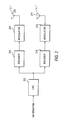
- FIG. 1 depicts system transmit equipment architecture using a 2x2 MIMO antenna system to which the method of the present invention is applied.
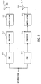
- FIG. 2 depicts another version of the system architecture for system transmit equipment shown in FIG. 1.
- FIG. 3 depicts an architecture for system transmit equipment using a 2x2 MIMO antenna system with separate error correction coding that applies the method of the present invention.
- FIG. 4 depicts an illustrative apportionment of code space among three users for a CDMA wireless communication system among three users.
- The present invention provides a method of conveying signaling information over forward and reverse links of a communication system having MIMO antenna systems. The signaling information conveyed over the signaling channels are formatted such that they allow relatively larger amounts of information to be conveyed by MIMO antenna systems. Using the method of the present invention and MIMO antennas systems, relatively larger amounts of signaling information can be conveyed to provide for the transmission and/or reception of the traffic information. In particular, the format of the forward link signaling channels provides an arrangement where system equipment are able to use antenna elements effectively of a MIMO antenna system to improve the throughput of the communication system. To support in communication systems that use MIMO antenna systems, the format of the reverse link signaling channels can be modified in any one of three basic ways: (1) reverse link signaling information are time division multiplexed; (2) additional channels are provided for the reverse link signaling information and (3) reverse link information are modulated at relatively higher order modulation. Further, exclusive portions of available signaling and traffic communication channels are assigned to different users who convey information using a MIMO antenna system. Channel assignment information is included in the forward link signaling information to assign available channels (traffic and/or signaling) to particular users. One or more channels can be assigned to a particular user. For ease of explanation, the method of the present invention will be described in the context of a CDMA communication system using a 2x2 MIMO antenna system (two transmit antennas, two receive antennas (not shown)) whose forward link signaling channel is the SPDCCH and whose reverse link signaling channels are the RACKCH and the RCQICH.
- Referring to FIG. 1, there is shown a typical system transmit equipment architecture of a communication system wherein a portion of the information to be transmitted is transmitted by one antenna and another portion of the information is transmitted by the other antenna. Cyclic Redundancy Check (CRC) error coding is applied to information to be transmitted. CRC coding, performed by
CRC coder 102, is a well known error detection scheme in which error detection bits are added to the information to allow receive equipment to determine whether the information, when received, contains errors. The output ofCRC coder 102 is applied toencoder 104 which applies channel coding operations on the error coded information. Channel coding comprises various well known channel coding operations in which bits are added to a block of information to add redundancy to the information thereby making the coded block more robust and less vulnerable to channel anomalies that cause errors to occur. A portion of the channel coded information and error correction coded information is applied tomodulator 106 and transmitted byantenna element 110. Another portion of the information is applied tomodulator 108 and transmitted byantenna element 112. The apportionment of the information to be transmitted can be performed at any point along the CRC, encoder, modulator and antenna system architecture. Also, the apportionment can occur prior to the traffic information being applied to the CRC coder. In FIG. 2, a transmit system equipment architecture similar to that shown in FIG. 1 is shown except that the apportionment of the information to be transmitted is done at the Encoder. Unlike FIG. 1, in FIG. 2 there are two channel encoders (204, 210) connected to modulators 206 and 212 respectively. The modulators are connected toantenna elements CRC coder 202, which is connected to the input of both channel encoders (204, 210), applies the proper CRC coding to the information that is to be transmitted. - When portions of the traffic information are transmitted by different antennas, all of the transmitted portions are to be received without errors; otherwise the original block of traffic information cannot be decoded. Therefore, when at least one of the portions is received with errors, the entire block of traffic information has to be retransmitted. Suppose the traffic information is divided into two portions (a first portion and a second portion) and one of the portions is received with errors. Because the decoding is performed on the entire block of traffic information it is not possible to determine which of the channels and corresponding antenna transmitted the erroneous portion. It may be that one of the antennas and its corresponding channel is causing the errors. The method of the present invention allows the traffic information to be retransmitted using different antennas by adding a "swapping" signaling information to the format of the SPDCCH. Swapping signaling information is information that indicate which system equipment is to be used to transmit the forward link traffic information. Depending on the size of the MIMO antenna system, the swapping information (e.g., swapping bits) can have any integer value equal to 2 or greater. In particular, still referring to FIG. 2, if a first portion of the traffic information was transmitted by
antenna 208 and the second portion of the traffic information is transmitted byantenna 214 and a portion of the transmitted traffic information was received with errors, the traffic information can be retransmitted whereby the second portion is now transmitted byantenna element 208 and the first portion is transmitted byantenna element 214. Alternatively, both portions can be retransmitted by eitherantenna element 208 orantenna element 214. Further, the traffic information can be retransmitted using the same antennas for the same portions. The value of the swapping bit information determines which antenna elements transmit which portions of the traffic information. The swapping information thus allows the communication system to select which antenna element is to retransmit traffic information. - Because relatively larger amounts of information are conveyed over the RACKCH and the RCQICH reverse link signaling channels, the method of the present invention provides three basic mechanisms to convey these signaling information. In the reverse link, when there are different signaling information associated with the same or different user equipment, a Time Division Multiplex (TDM) technique can be used to transmit these signaling information from user equipment to system equipment. The service provider will assign particular time slots to particular user equipment to allow each such user equipment to transmit signaling information over the reverse link at their designated time slots. In the CDMA communication system being discussed the time slots are 1.25 msec in duration.
- A second mechanism provided by the method of the present invention for the reverse link signaling channels is the addition of communication channels. For example, in a CDMA system using 64-ary Walsh codes (i.e., 6-bit Walsh codes), the system is modified to have 128-ary (i.e., 7-bit) Walsh codes. Walsh codes are a set of N-bit codes (each of which is unique within the set) that do not interfere with each other even when transmitted simultaneously with attached signaling and/or traffic information; N is an integer equal to 2 or greater. Thus, each Walsh code is akin to a separate and independent communication channel.
- The third mechanism provided by the method of the present invention is to allow the reverse link information to be transmitted at relatively higher order modulation. The modulation order refers to the amount of information represented by a transmitted symbol. In current CDMA systems, the reverse link information is transmitted using BPSK (Binary Phase Shift Keying) where a transmitted symbol represents one bit of information. In the method of the present invention, the reverse link signaling information is transmitted using QPSK (Quadrature Phase Shift Keying) where a transmitted symbol represents two bits of information. In transmitting the reverse link signaling information in accordance with the method of the present invention anyone of the above three mechanisms can be used and, more importantly, any combination of the above described three mechanism can be used. The Signal to Interference Noise Ratio (SINR) of signals conveyed over forward traffic channels are transmitted by users to system equipment over the RCQICH. The system defines a threshold power level and the user equipment measure the power levels of the signals transmitted over the traffic channels. The measured power levels and the defined threshold power levels are used by the user equipment to calculate the SINR for a particular traffic channel.
- Referring now to FIG. 3 there is shown a typical transmit system equipment architecture where information to be transmitted are CRC coded by different CRC coders (302, 312). Similarly the channel encoders (304, 314), modulators (306, 316) and antenna elements (308, 318) are separate distinct system transmit equipment. When one or more blocks of information are transmitted simultaneously some blocks are transmitted using one branch and the other blocks are transmitted using the other branch. If only one block is being transmitted, it is transmitted using one of the branches and the other branch is left unused. For clarity, with respect to FIG. 3, the term "branch" refers to one set of transmit equipment such as
CRC 302,Encoder 304,Modulator 306 and antenna 308 (hereinafter "the first branch"). Another set of transmit equipment, i.e., another "branch," is represented byCRC 312,Encoder 314,Modulator 316 and antenna 318 (hereinafter "the second branch"). Say, for example, two blocks of information are being transmitted. A first block of information is transmitted using the first branch while at the same time a second block of information is transmitted using the second branch. Because of the particular architecture of FIG. 3, each block of information has a different CRC. That is, the first block is coded byCRC 302 while the second block is coded byCRC 312. Because the blocks have different CRCs, there is greater flexibility afforded the transmit equipment because it does not have to retransmit both blocks of information in the case one of the blocks was received with errors; the equipment can retransmit only the block that was received with errors. Alternatively, the transmit equipment can retransmit the block by itself or retransmit the block simultaneously with a new block of information. This flexibility allows a service provider to increase a system's s throughput because it does not have to retransmit information that has already been received correctly (i.e., without errors). - To further allow a service provider the ability to convey greater amounts of information, portions of the set of communication channels (signaling and traffic channels) of the communication system are assigned to specific users. Thus, certain users will have certain forward and reverse link signaling channels associated with them. The system equipment will indicate the particular communication channels assigned to particular users with channel assignment information included in the forward link signaling channel (e.g., SPDCCH); that is, channel assignment information is signaling information that indicates which particular channels of a communication system are assigned to which users. More than one channel can be assigned to a particular user. Signaling information containing assigned set of communication channels are broadcast to intended users, but such signaling information are received and decoded by unintended users so that the users can determine their assigned portions of the available communication channels.
- Referring to FIG. 4,
Walsh code space 400 of available set of codes is shown. Suppose the code space is being apportioned between three users where each portion is delineated by boundaries. In the example shown user 1 is assigned the set of codes bounded by T1, user 2 is bounded by T1 and T2 and user 3 is bounded by T2 and T3. Information transmitted by system equipment over an SPDCCH contains the boundary information (i.e., a type of channel assignment information) indicating that T1 is the boundary for user 1. This information is broadcast by the transmit equipment and is thus not only received and decoded by user 1, but is also received and decoded by users 2 and 3. Similarly signaling information over an SPDCCH intended for user 2 contains the boundary information T2 and signaling information transmitted over the SPDCCH intended for user 3 contains boundary information T3. User 1 then is able to determine that all codes above boundary T1 are available for use. User 2 is able to determine that all codes above boundary T2 but below boundary T1 are available for use. User 3 is able to determine that all codes above boundary T3 but below boundary T2 are available for use. Thus, each user is able to determine its portion of available codes from the reception and decoding of signaling information intended for that user and signaling information intended for other users. For example, user 2 was able to determine its available code portion from its received signaling information and signaling information intended for user 1. Similarly, user 3 uses its own received signaling boundary information and signaling boundary information intended for user 2 to determine its available code portion. Therefore, in general, a user equipment is able to determine its set of available channels from signaling information it receives and from signaling information intended for other user equipment. Thus the channel assignment information is called signaling boundary information for CDMA systems because such systems, as explained earlier, represent their channels with Walsh codes. - It will be understood that the method of the present invention is applicable to other types of wireless communication systems and is not limited to the CDMA communication system discussed above. Further, the method of the present invention is also applicable to wireline communication systems.
Claims (10)
- A method of communication comprising the step of:providing a forward link signaling channel format having swapping signaling information for retransmitting traffic information using at least one of a plurality of antenna elements.
- A method of communication comprising the step of:providing a reverse link signaling channel format where any one or any combination of the following three mechanisms is used:(1) reverse link signaling information is time division multiplexed;(2) additional communication channels are provided;(3) reverse link signaling information is transmitted at relatively higher order modulation.
- The method of claim 1 further comprising the step of providing additional communication channels that are assigned to particular users of the communication system with the use of channel assignment information in the forward link signaling information.
- The method of claim 1 further comprising the step of providing additional communication channels assigned to particular users of a CDMA communication system by using additional Walsh codes.
- The method of claim 1 where different portions of the traffic information is transmitted by different antenna elements of a Multiple Input Multiple Output antenna system based on the swapping signaling information.
- The method of claim 1 where a CDMA communication system is used for communication and the forward link signaling channel is an SPDCCH that includes swapping bits for indicating which antenna is to transmit or retransmit the traffic information and boundary information for assigning particular channels to particular users.
- The method of claim 2 further comprising the step of providing additional communication channels that are assigned to particular users of the communication system with the use of channel assignment information in the forward link signaling information.
- The method of claim 2 further comprising the step of providing additional communication channels assigned to particular users of a CDMA communication system by using additional Walsh codes.
- The method of claim 2 where different portions of the traffic information is transmitted by different antenna elements of a Multiple Input Multiple Output antenna system based on the swapping signaling information.
- The method of claim 2 where a CDMA system is used for communication and the reverse link signaling channels are the RACKCH and the RQCICH where the RACKCH and the RCQICH information are time division multiplexed, modulated using QPSK modulation and where 128-ary Walsh codes are used in the communication system to convey information.
Applications Claiming Priority (2)
| Application Number | Priority Date | Filing Date | Title |
|---|---|---|---|
| US10/261,283 US7391755B2 (en) | 2002-09-30 | 2002-09-30 | Signaling and control mechanisms in MIMO harq schemes for wireless communication systems |
| US261283 | 2008-10-30 |
Publications (2)
| Publication Number | Publication Date |
|---|---|
| EP1404048A1 true EP1404048A1 (en) | 2004-03-31 |
| EP1404048B1 EP1404048B1 (en) | 2016-09-28 |
Family
ID=31977942
Family Applications (1)
| Application Number | Title | Priority Date | Filing Date |
|---|---|---|---|
| EP03255072.5A Expired - Lifetime EP1404048B1 (en) | 2002-09-30 | 2003-08-14 | Signalling mechanisms in MIMO HARQ schemes for wireless communication systems |
Country Status (4)
| Country | Link |
|---|---|
| US (1) | US7391755B2 (en) |
| EP (1) | EP1404048B1 (en) |
| JP (1) | JP4397651B2 (en) |
| KR (1) | KR100979657B1 (en) |
Cited By (12)
| Publication number | Priority date | Publication date | Assignee | Title |
|---|---|---|---|---|
| WO2006070465A1 (en) | 2004-12-28 | 2006-07-06 | Fujitsu Limited | Retransmission controller |
| WO2007004285A1 (en) * | 2005-07-04 | 2007-01-11 | Matsushita Electric Industrial Co., Ltd. | Wireless communication method, wireless transmitter and wireless receiver |
| WO2008125923A1 (en) * | 2006-08-21 | 2008-10-23 | Koninklijke Philips Electronics N.V. | Indicating retransmission processes in multi-beam systems |
| US20100067459A1 (en) * | 2006-10-31 | 2010-03-18 | Goeransson Bo | HARQ in Spatial Multiplexing MIMO System |
| CN101138185B (en) * | 2005-03-11 | 2010-07-21 | 松下电器产业株式会社 | MIMO transmitting apparatus and data retransmission method in MIMO system |
| EP1805925A4 (en) * | 2004-10-25 | 2011-06-22 | Lg Electronics Inc | A method of selecting retransmission format in a wireless communication multiple antenna system |
| EP1835631A4 (en) * | 2004-12-28 | 2012-02-22 | Fujitsu Ltd | TRANSMISSION METHOD BY SIGNALING CHANNEL, BASE STATION AND TERMINAL |
| EP2518921A1 (en) * | 2004-09-13 | 2012-10-31 | Panasonic Corporation | Automatic retransmission request (arq) control system and retransmission method in MIMO-OFDM system |
| EP2066055A4 (en) * | 2006-09-29 | 2013-01-16 | Fujitsu Ltd | WIRELESS COMMUNICATION SYSTEM AND TRANSMITTER AND RECEIVER THEREFOR |
| CN103929230A (en) * | 2006-10-27 | 2014-07-16 | 富士通株式会社 | Wireless communication system and wireless communication method |
| EP2086145A3 (en) * | 2008-01-30 | 2015-10-14 | Optis Cellular Technology, LLC | Method for transmitting downlink control information |
| US9949239B2 (en) | 2007-08-08 | 2018-04-17 | Telefonaktiebolaget Lm Ericsson (Publ) | Uplink scrambling during random access |
Families Citing this family (37)
| Publication number | Priority date | Publication date | Assignee | Title |
|---|---|---|---|---|
| EP1615365A4 (en) * | 2003-06-30 | 2011-05-11 | Fujitsu Ltd | MULTI-INPUT AND MULTI-OUTPUT TRANSMISSION SYSTEM |
| US20050068917A1 (en) * | 2003-09-17 | 2005-03-31 | Sayeedi Shahab M. | Providing and maintaining F-PDCH service in a mobile communication system |
| US7684372B2 (en) | 2004-05-04 | 2010-03-23 | Ipwireless, Inc. | Signaling MIMO allocations |
| JP4589711B2 (en) | 2004-12-14 | 2010-12-01 | 富士通株式会社 | Wireless communication system and wireless communication device |
| CN1790976A (en) * | 2004-12-17 | 2006-06-21 | 松下电器产业株式会社 | Re-transmitting method for multi-antenna transmission |
| JP2006209462A (en) * | 2005-01-28 | 2006-08-10 | Kyocera Corp | Terminal device |
| CN1832390A (en) * | 2005-03-07 | 2006-09-13 | 松下电器产业株式会社 | A retransmission method based on reliability estimation for multi-antenna adaptive transmission |
| CN1832391A (en) * | 2005-03-11 | 2006-09-13 | 松下电器产业株式会社 | Adaptive retransmission method and device in multi-antenna communication system |
| JP4689316B2 (en) * | 2005-03-28 | 2011-05-25 | 富士通株式会社 | Error detection method of control information for transmitting downlink channel of radio communication and mobile terminal |
| JP4884722B2 (en) * | 2005-03-31 | 2012-02-29 | 株式会社エヌ・ティ・ティ・ドコモ | Wireless communication apparatus and wireless communication method |
| RU2408987C2 (en) * | 2005-04-01 | 2011-01-10 | Нтт Досомо, Инк. | Transmitting device and method of signal transmission |
| JP2007221178A (en) | 2005-04-01 | 2007-08-30 | Ntt Docomo Inc | Transmitting apparatus and transmitting method |
| US7961700B2 (en) | 2005-04-28 | 2011-06-14 | Qualcomm Incorporated | Multi-carrier operation in data transmission systems |
| US8855704B2 (en) * | 2005-08-26 | 2014-10-07 | Qualcomm Incorporated | Fast cell selection in TD-CDMA (UMTS TDD) |
| KR100690274B1 (en) * | 2005-09-12 | 2007-03-09 | 삼성전자주식회사 | Cyclic redundancy check device and multi-channel communication system for multi-channel serial communication |
| US8130727B2 (en) * | 2005-10-27 | 2012-03-06 | Qualcomm Incorporated | Quasi-orthogonal allocation of codes in TD-CDMA systems |
| US8068464B2 (en) | 2005-10-27 | 2011-11-29 | Qualcomm Incorporated | Varying scrambling/OVSF codes within a TD-CDMA slot to overcome jamming effect by a dominant interferer |
| US7684808B1 (en) * | 2006-03-08 | 2010-03-23 | Sprint Spectrum L.P. | Limiting channel element usage based on communication type |
| US9130791B2 (en) | 2006-03-20 | 2015-09-08 | Qualcomm Incorporated | Uplink channel estimation using a signaling channel |
| US7929908B2 (en) * | 2006-05-24 | 2011-04-19 | The Boeing Company | Method and system for controlling a network for power beam transmission |
| CN101473553A (en) * | 2006-06-23 | 2009-07-01 | 松下电器产业株式会社 | Retransmission of MIMO communication system |
| AU2011224065B2 (en) * | 2006-10-31 | 2013-10-03 | Telefonaktiebolaget L M Ericsson (Publ) | Harq in spatial multiplexing mimo system |
| US20080151871A1 (en) * | 2006-12-22 | 2008-06-26 | Nokia Corporation | Power-Efficient Multi-Branch Reception |
| ZA200905127B (en) * | 2007-02-14 | 2010-09-29 | Ericsson Telefon Ab L M | Codeword to layer mapping in a system implementing HARQ |
| KR100928391B1 (en) | 2007-04-06 | 2009-11-23 | 인하대학교 산학협력단 | Method and apparatus for data retransmission based on antenna scheduling in multi-antenna system |
| JP5035338B2 (en) * | 2007-05-21 | 2012-09-26 | 富士通株式会社 | Data retransmission method and wireless communication system to which the method is applied |
| JP5207698B2 (en) * | 2007-09-28 | 2013-06-12 | 三菱電機株式会社 | Reception device and transmission path estimation method |
| JP4812779B2 (en) * | 2008-01-07 | 2011-11-09 | 富士通株式会社 | Mobile communication system, communication method therefor, and transmission station |
| KR100908064B1 (en) * | 2008-01-30 | 2009-07-15 | 엘지전자 주식회사 | Downlink control information delivery method |
| KR101481584B1 (en) * | 2008-06-24 | 2015-01-13 | 엘지전자 주식회사 | Method of defining transmission block-codeword mapping relationship and downlink signal transmission method using the same |
| US8830885B2 (en) * | 2008-08-21 | 2014-09-09 | Qualcomm Incorporated | Multichannel architecture for high throughput modems |
| US8804611B2 (en) * | 2009-02-12 | 2014-08-12 | Qualcomm Incorporated | Method and apparatus for acknowledging successful reception of a data transmission for multi-access compatibility in a wireless communication system |
| US8472943B1 (en) * | 2010-06-03 | 2013-06-25 | Sprint Spectrum L.P. | Method and system for using multiple channel elements |
| JP5147917B2 (en) * | 2010-10-12 | 2013-02-20 | パナソニック株式会社 | Receiving apparatus and receiving method |
| KR101109575B1 (en) * | 2011-06-27 | 2012-01-31 | 한철호 | Gap adjuster |
| US11375580B1 (en) * | 2020-09-23 | 2022-06-28 | T-Mobile Innovations Llc | Managing secondary node and channel assignment based on wireless device characteristics |
| CN112526979B (en) * | 2020-12-16 | 2023-06-09 | 中国兵器装备集团自动化研究所 | Serial communication interface diagnosis system and method with multiple redundancy architecture |
Citations (3)
| Publication number | Priority date | Publication date | Assignee | Title |
|---|---|---|---|---|
| US6127971A (en) * | 1997-07-16 | 2000-10-03 | At&T Corp | Combined array processing and space-time coding |
| US20010002904A1 (en) * | 1997-12-17 | 2001-06-07 | Tantivy Communications, Inc. | Fast acquisition of traffic channels for a highly variable data rate reverse link of a CDMA wireless communication system |
| EP1207635A1 (en) * | 2000-11-17 | 2002-05-22 | Lucent Technologies Inc. | Downlink and uplink channel structures for downlink shared channel system |
Family Cites Families (9)
| Publication number | Priority date | Publication date | Assignee | Title |
|---|---|---|---|---|
| KR100299128B1 (en) * | 1998-06-12 | 2001-11-05 | 윤종용 | Apparatus and method for power control bit pattern transmission and reception according to transmission antenna in mobile communication system |
| KR100516671B1 (en) * | 1999-05-24 | 2005-09-22 | 삼성전자주식회사 | Variable-length Data Transmitting and Receiving Apparatus and Method in accordance with Radio Link Protocol for Mobile Telecommunication System |
| US6463279B1 (en) * | 1999-11-17 | 2002-10-08 | Globalstar L.P. | Channel frequency allocation for multiple-satellite communication network |
| US20020154705A1 (en) | 2000-03-22 | 2002-10-24 | Walton Jay R. | High efficiency high performance communications system employing multi-carrier modulation |
| US7031419B2 (en) * | 2001-06-29 | 2006-04-18 | Nokia Corporation | Data transmission method and system |
| US7167461B2 (en) * | 2001-10-15 | 2007-01-23 | Qualcomm Incorporated | Method and apparatus for processing shared subpackets in a communication system |
| US7295624B2 (en) * | 2002-03-06 | 2007-11-13 | Texas Instruments Incorporated | Wireless system with hybrid automatic retransmission request in interference-limited communications |
| US7379416B2 (en) * | 2002-03-13 | 2008-05-27 | Lsi Logic Corporation | Forward packet data channel with parallel sub-packets |
| US7352722B2 (en) * | 2002-05-13 | 2008-04-01 | Qualcomm Incorporated | Mitigation of link imbalance in a wireless communication system |
-
2002
- 2002-09-30 US US10/261,283 patent/US7391755B2/en not_active Expired - Lifetime
-
2003
- 2003-08-14 EP EP03255072.5A patent/EP1404048B1/en not_active Expired - Lifetime
- 2003-08-21 JP JP2003297364A patent/JP4397651B2/en not_active Expired - Lifetime
- 2003-08-21 KR KR1020030057888A patent/KR100979657B1/en not_active Expired - Lifetime
Patent Citations (3)
| Publication number | Priority date | Publication date | Assignee | Title |
|---|---|---|---|---|
| US6127971A (en) * | 1997-07-16 | 2000-10-03 | At&T Corp | Combined array processing and space-time coding |
| US20010002904A1 (en) * | 1997-12-17 | 2001-06-07 | Tantivy Communications, Inc. | Fast acquisition of traffic channels for a highly variable data rate reverse link of a CDMA wireless communication system |
| EP1207635A1 (en) * | 2000-11-17 | 2002-05-22 | Lucent Technologies Inc. | Downlink and uplink channel structures for downlink shared channel system |
Cited By (43)
| Publication number | Priority date | Publication date | Assignee | Title |
|---|---|---|---|---|
| US9680611B2 (en) | 2004-09-13 | 2017-06-13 | Inventergy, Inc. | Automatic retransmission in communications systems |
| US9015546B2 (en) | 2004-09-13 | 2015-04-21 | Inventergy, Inc. | Automatic retransmission request control system and retransmission method in mimo-OFDM system |
| US8775890B2 (en) | 2004-09-13 | 2014-07-08 | Inventergy, Inc. | Automatic retransmission request control system and retransmission method in MIMO-OFDM system |
| USRE48260E1 (en) | 2004-09-13 | 2020-10-13 | Invt Spe Llc | Automatic retransmission in communications systems |
| US9425924B2 (en) | 2004-09-13 | 2016-08-23 | Inventergy, Inc. | Automatic retransmission in communications systems |
| EP2518921A1 (en) * | 2004-09-13 | 2012-10-31 | Panasonic Corporation | Automatic retransmission request (arq) control system and retransmission method in MIMO-OFDM system |
| US9397794B2 (en) | 2004-09-13 | 2016-07-19 | Inventergy, Inc. | Automatic retransmission in communications systems |
| EP1805925A4 (en) * | 2004-10-25 | 2011-06-22 | Lg Electronics Inc | A method of selecting retransmission format in a wireless communication multiple antenna system |
| EP2458822A1 (en) * | 2004-12-28 | 2012-05-30 | Fujitsu Limited | Repeat request control apparatus |
| US9432976B2 (en) | 2004-12-28 | 2016-08-30 | Fujitsu Limited | Control channel transmitting method, base station and terminal |
| WO2006070465A1 (en) | 2004-12-28 | 2006-07-06 | Fujitsu Limited | Retransmission controller |
| EP1833228A4 (en) * | 2004-12-28 | 2011-06-01 | Fujitsu Ltd | Retransmission controller |
| EP1835631A4 (en) * | 2004-12-28 | 2012-02-22 | Fujitsu Ltd | TRANSMISSION METHOD BY SIGNALING CHANNEL, BASE STATION AND TERMINAL |
| CN101138185B (en) * | 2005-03-11 | 2010-07-21 | 松下电器产业株式会社 | MIMO transmitting apparatus and data retransmission method in MIMO system |
| US8488701B2 (en) | 2005-07-04 | 2013-07-16 | Panasonic Corporation | Wireless communication method, wireless transmitter and wireless receiver |
| US8194786B2 (en) | 2005-07-04 | 2012-06-05 | Panasonic Corporation | Wireless communication method, wireless transmitter and wireless receiver |
| US8681892B2 (en) | 2005-07-04 | 2014-03-25 | Panasonic Corporation | Wireless communication method, wireless transmitter and wireless receiver |
| WO2007004285A1 (en) * | 2005-07-04 | 2007-01-11 | Matsushita Electric Industrial Co., Ltd. | Wireless communication method, wireless transmitter and wireless receiver |
| WO2008125923A1 (en) * | 2006-08-21 | 2008-10-23 | Koninklijke Philips Electronics N.V. | Indicating retransmission processes in multi-beam systems |
| EP2066055A4 (en) * | 2006-09-29 | 2013-01-16 | Fujitsu Ltd | WIRELESS COMMUNICATION SYSTEM AND TRANSMITTER AND RECEIVER THEREFOR |
| CN103929230A (en) * | 2006-10-27 | 2014-07-16 | 富士通株式会社 | Wireless communication system and wireless communication method |
| CN103929230B (en) * | 2006-10-27 | 2018-09-11 | 富士通株式会社 | Wireless communication system and wireless communications method |
| EP2849380A1 (en) * | 2006-10-31 | 2015-03-18 | Telefonaktiebolaget L M Ericsson (PUBL) | Telecommunication system and error control in such system |
| US10326563B2 (en) | 2006-10-31 | 2019-06-18 | Telefonaktiebolaget Lm Ericsson (Publ) | HARQ in spatial multiplexing MIMO system |
| US9392616B2 (en) | 2006-10-31 | 2016-07-12 | Telefonaktiebolaget Lm Ericsson (Publ) | HARQ in spatial multiplexing MIMO system |
| US12166592B2 (en) | 2006-10-31 | 2024-12-10 | Telefonaktiebolaget Lm Ericsson (Publ) | HARQ in spatial multiplexing MIMO system |
| US8498246B2 (en) | 2006-10-31 | 2013-07-30 | Telefonaktiebolaget Lm Ericsson (Publ) | HARQ in spatial multiplexing MIMO system |
| CN103023629A (en) * | 2006-10-31 | 2013-04-03 | 艾利森电话股份有限公司 | HARQ in spatial multiplexing MIMO system |
| US8102805B2 (en) | 2006-10-31 | 2012-01-24 | Telefonaktiebolaget Lm Ericsson (Publ) | HARQ in spatial multiplexing MIMO system |
| US9866353B2 (en) | 2006-10-31 | 2018-01-09 | Telefonaktiebolaget Lm Ericsson (Publ) | HARQ in spatial multiplexing MIMO system |
| EP4236145A3 (en) * | 2006-10-31 | 2023-10-11 | Telefonaktiebolaget LM Ericsson (publ) | Method and apparatus for error control in telecommunications systems |
| EP2078368A4 (en) * | 2006-10-31 | 2011-09-07 | Ericsson Telefon Ab L M | Harq in spatial multiplexing mimo system |
| US11777670B2 (en) | 2006-10-31 | 2023-10-03 | Telefonaktiebolaget Lm Ericsson (Publ) | HARQ in spatial multiplexing MIMO system |
| CN103023629B (en) * | 2006-10-31 | 2015-10-21 | 艾利森电话股份有限公司 | HARQ in spatial multiplexing MIMO system |
| EP3503449A1 (en) * | 2006-10-31 | 2019-06-26 | Telefonaktiebolaget LM Ericsson (publ) | Method and apparatuss for error control in telecommunications systems |
| US20100067459A1 (en) * | 2006-10-31 | 2010-03-18 | Goeransson Bo | HARQ in Spatial Multiplexing MIMO System |
| EP3780450A1 (en) * | 2006-10-31 | 2021-02-17 | Telefonaktiebolaget LM Ericsson (publ) | Method and apparatus for error control in telecommunications systems |
| US11101942B2 (en) | 2006-10-31 | 2021-08-24 | Telefonaktiebolaget Lm Ericsson (Publ) | HARQ in spatial multiplexing MIMO system |
| US11330567B2 (en) | 2007-08-08 | 2022-05-10 | Telefonaktiebolaget Lm Ericsson (Publ) | Uplink scrambling during random access |
| US9949239B2 (en) | 2007-08-08 | 2018-04-17 | Telefonaktiebolaget Lm Ericsson (Publ) | Uplink scrambling during random access |
| US12089218B2 (en) | 2007-08-08 | 2024-09-10 | Telefonaktiebolaget Lm Ericsson (Publ) | Uplink scrambling during random access |
| EP3454492A1 (en) * | 2008-01-30 | 2019-03-13 | Optis Cellular Technology, LLC | Method for transmitting downlink control information |
| EP2086145A3 (en) * | 2008-01-30 | 2015-10-14 | Optis Cellular Technology, LLC | Method for transmitting downlink control information |
Also Published As
| Publication number | Publication date |
|---|---|
| KR20040028492A (en) | 2004-04-03 |
| JP2004135304A (en) | 2004-04-30 |
| KR100979657B1 (en) | 2010-09-02 |
| US20040062221A1 (en) | 2004-04-01 |
| JP4397651B2 (en) | 2010-01-13 |
| US7391755B2 (en) | 2008-06-24 |
| EP1404048B1 (en) | 2016-09-28 |
Similar Documents
| Publication | Publication Date | Title |
|---|---|---|
| US7391755B2 (en) | Signaling and control mechanisms in MIMO harq schemes for wireless communication systems | |
| EP1211839B1 (en) | Sub-packet adaptation in a wireless communication system | |
| TWI359586B (en) | Method for data transmission, mobile station, base | |
| US7221648B2 (en) | Rate adaptation in a wireless communication system | |
| US8000326B2 (en) | Method and apparatus for fragmenting a control message in wireless communication system | |
| CN100370723C (en) | Communication system and method for transmitting data in it | |
| CA2313978C (en) | Data link protocol for wireless systems | |
| JP2002527939A (en) | Data communication method and system using applied hybrid ARQ technique | |
| MX2010011830A (en) | Method and apparatus in a telecommunications network. | |
| US8514691B2 (en) | Feedback information relating to a mobile communications system using carrier aggregation | |
| RU2262195C2 (en) | Method and device for adjustment of power of controlling information transmission in mobile telecommunications system | |
| CN100581075C (en) | Transmission method of downlink control signal in MIMO system | |
| KR101111515B1 (en) | Method for Transmitting and Receiving Data | |
| US20120218925A1 (en) | Wireless communication method, wireless transmitter and wireless receiver | |
| WO2007000696A1 (en) | Method and apparatus for h-arq in a wireless communication system | |
| EP1508991A1 (en) | Data error control method | |
| JP2003523645A (en) | Wireless communication system and method supporting link adaptation mode | |
| US8559557B2 (en) | Telecommunication method and apparatus | |
| US20090003420A1 (en) | Systems and methods for embedding a first signal in the coding of a second signal | |
| US7190685B2 (en) | Control information transmission in a wireless communication system | |
| CA2546389C (en) | Transmission power control apparatus in wireless communication system and method therefor | |
| RATE et al. | Das et a].(45) Date of Patent: Oct. 14, 2008 | |
| US20050170830A1 (en) | Link adaptation in a mobile communication network | |
| HK1113711B (en) | Method for transmitting and receiving data |
Legal Events
| Date | Code | Title | Description |
|---|---|---|---|
| PUAI | Public reference made under article 153(3) epc to a published international application that has entered the european phase |
Free format text: ORIGINAL CODE: 0009012 |
|
| 17P | Request for examination filed |
Effective date: 20030902 |
|
| AK | Designated contracting states |
Kind code of ref document: A1 Designated state(s): AT BE BG CH CY CZ DE DK EE ES FI FR GB GR HU IE IT LI LU MC NL PT RO SE SI SK TR |
|
| AX | Request for extension of the european patent |
Extension state: AL LT LV MK |
|
| 17Q | First examination report despatched |
Effective date: 20040511 |
|
| AKX | Designation fees paid |
Designated state(s): DE FR GB |
|
| 17Q | First examination report despatched |
Effective date: 20040511 |
|
| RAP3 | Party data changed (applicant data changed or rights of an application transferred) |
Owner name: LUCENT TECHNOLOGIES INC. |
|
| RAP1 | Party data changed (applicant data changed or rights of an application transferred) |
Owner name: ALCATEL-LUCENT USA INC. |
|
| 111Z | Information provided on other rights and legal means of execution |
Free format text: DE FR GB Effective date: 20130410 |
|
| D11X | Information provided on other rights and legal means of execution (deleted) | ||
| RIC1 | Information provided on ipc code assigned before grant |
Ipc: H04B 7/06 20060101ALN20160317BHEP Ipc: H04L 1/18 20060101AFI20160317BHEP Ipc: H04B 7/02 20060101ALI20160317BHEP Ipc: H04L 1/00 20060101ALN20160317BHEP |
|
| GRAP | Despatch of communication of intention to grant a patent |
Free format text: ORIGINAL CODE: EPIDOSNIGR1 |
|
| RIN1 | Information on inventor provided before grant (corrected) |
Inventor name: KOGIANTIS, ACHILLES GEORGE Inventor name: SHARMA, NARESH Inventor name: LIU, JUNG-TAO Inventor name: GOPALAKRISHNAN, NANDU Inventor name: RUDRAPATNA, ASHOK N. |
|
| RIC1 | Information provided on ipc code assigned before grant |
Ipc: H04L 1/00 20060101ALN20160412BHEP Ipc: H04L 1/18 20060101AFI20160412BHEP Ipc: H04B 7/06 20060101ALN20160412BHEP Ipc: H04B 7/02 20060101ALI20160412BHEP |
|
| INTG | Intention to grant announced |
Effective date: 20160428 |
|
| GRAS | Grant fee paid |
Free format text: ORIGINAL CODE: EPIDOSNIGR3 |
|
| GRAA | (expected) grant |
Free format text: ORIGINAL CODE: 0009210 |
|
| RAP1 | Party data changed (applicant data changed or rights of an application transferred) |
Owner name: ALCATEL LUCENT |
|
| AK | Designated contracting states |
Kind code of ref document: B1 Designated state(s): DE FR GB |
|
| REG | Reference to a national code |
Ref country code: GB Ref legal event code: FG4D |
|
| REG | Reference to a national code |
Ref country code: DE Ref legal event code: R081 Ref document number: 60349441 Country of ref document: DE Owner name: NOKIA TECHNOLOGIES OY, FI Free format text: FORMER OWNER: LUCENT TECHNOLOGIES INC., MURRAY HILL, N.J., US |
|
| REG | Reference to a national code |
Ref country code: DE Ref legal event code: R096 Ref document number: 60349441 Country of ref document: DE |
|
| REG | Reference to a national code |
Ref country code: DE Ref legal event code: R097 Ref document number: 60349441 Country of ref document: DE |
|
| PLBE | No opposition filed within time limit |
Free format text: ORIGINAL CODE: 0009261 |
|
| STAA | Information on the status of an ep patent application or granted ep patent |
Free format text: STATUS: NO OPPOSITION FILED WITHIN TIME LIMIT |
|
| REG | Reference to a national code |
Ref country code: FR Ref legal event code: PLFP Year of fee payment: 15 |
|
| 26N | No opposition filed |
Effective date: 20170629 |
|
| REG | Reference to a national code |
Ref country code: FR Ref legal event code: PLFP Year of fee payment: 16 |
|
| REG | Reference to a national code |
Ref country code: DE Ref legal event code: R082 Ref document number: 60349441 Country of ref document: DE Representative=s name: LOUIS POEHLAU LOHRENTZ PATENTANWAELTE PARTNERS, DE Ref country code: DE Ref legal event code: R082 Ref document number: 60349441 Country of ref document: DE Representative=s name: LOUIS, POEHLAU, LOHRENTZ, DE Ref country code: DE Ref legal event code: R081 Ref document number: 60349441 Country of ref document: DE Owner name: NOKIA TECHNOLOGIES OY, FI Free format text: FORMER OWNER: ALCATEL LUCENT, BOULOGNE BILLANCOURT, FR |
|
| REG | Reference to a national code |
Ref country code: GB Ref legal event code: 732E Free format text: REGISTERED BETWEEN 20200402 AND 20200408 |
|
| PGFP | Annual fee paid to national office [announced via postgrant information from national office to epo] |
Ref country code: GB Payment date: 20220630 Year of fee payment: 20 |
|
| PGFP | Annual fee paid to national office [announced via postgrant information from national office to epo] |
Ref country code: DE Payment date: 20220705 Year of fee payment: 20 |
|
| PGFP | Annual fee paid to national office [announced via postgrant information from national office to epo] |
Ref country code: FR Payment date: 20220709 Year of fee payment: 20 |
|
| REG | Reference to a national code |
Ref country code: DE Ref legal event code: R071 Ref document number: 60349441 Country of ref document: DE |
|
| REG | Reference to a national code |
Ref country code: GB Ref legal event code: PE20 Expiry date: 20230813 |
|
| PG25 | Lapsed in a contracting state [announced via postgrant information from national office to epo] |
Ref country code: GB Free format text: LAPSE BECAUSE OF EXPIRATION OF PROTECTION Effective date: 20230813 |