EP1404009A1 - Rotor and method for repairing the same - Google Patents
Rotor and method for repairing the same Download PDFInfo
- Publication number
- EP1404009A1 EP1404009A1 EP20030016992 EP03016992A EP1404009A1 EP 1404009 A1 EP1404009 A1 EP 1404009A1 EP 20030016992 EP20030016992 EP 20030016992 EP 03016992 A EP03016992 A EP 03016992A EP 1404009 A1 EP1404009 A1 EP 1404009A1
- Authority
- EP
- European Patent Office
- Prior art keywords
- outboard
- rotor
- fillet
- inboard
- wedge
- Prior art date
- Legal status (The legal status is an assumption and is not a legal conclusion. Google has not performed a legal analysis and makes no representation as to the accuracy of the status listed.)
- Granted
Links
- 238000000034 method Methods 0.000 title claims abstract description 22
- 238000003754 machining Methods 0.000 claims description 11
- 238000009659 non-destructive testing Methods 0.000 claims description 4
- 150000001875 compounds Chemical class 0.000 claims description 2
- 230000007704 transition Effects 0.000 claims description 2
- 230000003247 decreasing effect Effects 0.000 claims 1
- 238000005336 cracking Methods 0.000 abstract description 3
- 238000004804 winding Methods 0.000 description 7
- 238000009987 spinning Methods 0.000 description 3
- 238000012360 testing method Methods 0.000 description 3
- 230000015572 biosynthetic process Effects 0.000 description 2
- 230000001066 destructive effect Effects 0.000 description 2
- 230000000712 assembly Effects 0.000 description 1
- 238000000429 assembly Methods 0.000 description 1
- 238000005352 clarification Methods 0.000 description 1
- 125000004122 cyclic group Chemical group 0.000 description 1
- 230000007423 decrease Effects 0.000 description 1
- 238000009826 distribution Methods 0.000 description 1
- 238000007689 inspection Methods 0.000 description 1
- 238000009434 installation Methods 0.000 description 1
- 238000004519 manufacturing process Methods 0.000 description 1
- 238000010248 power generation Methods 0.000 description 1
- 230000002035 prolonged effect Effects 0.000 description 1
- 230000000717 retained effect Effects 0.000 description 1
Images



Classifications
-
- H—ELECTRICITY
- H02—GENERATION; CONVERSION OR DISTRIBUTION OF ELECTRIC POWER
- H02K—DYNAMO-ELECTRIC MACHINES
- H02K15/00—Processes or apparatus specially adapted for manufacturing, assembling, maintaining or repairing of dynamo-electric machines
- H02K15/50—Disassembling, repairing or modifying dynamo-electric machines
-
- Y—GENERAL TAGGING OF NEW TECHNOLOGICAL DEVELOPMENTS; GENERAL TAGGING OF CROSS-SECTIONAL TECHNOLOGIES SPANNING OVER SEVERAL SECTIONS OF THE IPC; TECHNICAL SUBJECTS COVERED BY FORMER USPC CROSS-REFERENCE ART COLLECTIONS [XRACs] AND DIGESTS
- Y10—TECHNICAL SUBJECTS COVERED BY FORMER USPC
- Y10T—TECHNICAL SUBJECTS COVERED BY FORMER US CLASSIFICATION
- Y10T29/00—Metal working
- Y10T29/49—Method of mechanical manufacture
- Y10T29/49002—Electrical device making
- Y10T29/49009—Dynamoelectric machine
-
- Y—GENERAL TAGGING OF NEW TECHNOLOGICAL DEVELOPMENTS; GENERAL TAGGING OF CROSS-SECTIONAL TECHNOLOGIES SPANNING OVER SEVERAL SECTIONS OF THE IPC; TECHNICAL SUBJECTS COVERED BY FORMER USPC CROSS-REFERENCE ART COLLECTIONS [XRACs] AND DIGESTS
- Y10—TECHNICAL SUBJECTS COVERED BY FORMER USPC
- Y10T—TECHNICAL SUBJECTS COVERED BY FORMER US CLASSIFICATION
- Y10T29/00—Metal working
- Y10T29/49—Method of mechanical manufacture
- Y10T29/49002—Electrical device making
- Y10T29/49009—Dynamoelectric machine
- Y10T29/49011—Commutator or slip ring assembly
-
- Y—GENERAL TAGGING OF NEW TECHNOLOGICAL DEVELOPMENTS; GENERAL TAGGING OF CROSS-SECTIONAL TECHNOLOGIES SPANNING OVER SEVERAL SECTIONS OF THE IPC; TECHNICAL SUBJECTS COVERED BY FORMER USPC CROSS-REFERENCE ART COLLECTIONS [XRACs] AND DIGESTS
- Y10—TECHNICAL SUBJECTS COVERED BY FORMER USPC
- Y10T—TECHNICAL SUBJECTS COVERED BY FORMER US CLASSIFICATION
- Y10T29/00—Metal working
- Y10T29/49—Method of mechanical manufacture
- Y10T29/49002—Electrical device making
- Y10T29/49009—Dynamoelectric machine
- Y10T29/49012—Rotor
-
- Y—GENERAL TAGGING OF NEW TECHNOLOGICAL DEVELOPMENTS; GENERAL TAGGING OF CROSS-SECTIONAL TECHNOLOGIES SPANNING OVER SEVERAL SECTIONS OF THE IPC; TECHNICAL SUBJECTS COVERED BY FORMER USPC CROSS-REFERENCE ART COLLECTIONS [XRACs] AND DIGESTS
- Y10—TECHNICAL SUBJECTS COVERED BY FORMER USPC
- Y10T—TECHNICAL SUBJECTS COVERED BY FORMER US CLASSIFICATION
- Y10T29/00—Metal working
- Y10T29/49—Method of mechanical manufacture
- Y10T29/49718—Repairing
- Y10T29/49721—Repairing with disassembling
- Y10T29/49723—Repairing with disassembling including reconditioning of part
- Y10T29/49725—Repairing with disassembling including reconditioning of part by shaping
-
- Y—GENERAL TAGGING OF NEW TECHNOLOGICAL DEVELOPMENTS; GENERAL TAGGING OF CROSS-SECTIONAL TECHNOLOGIES SPANNING OVER SEVERAL SECTIONS OF THE IPC; TECHNICAL SUBJECTS COVERED BY FORMER USPC CROSS-REFERENCE ART COLLECTIONS [XRACs] AND DIGESTS
- Y10—TECHNICAL SUBJECTS COVERED BY FORMER USPC
- Y10T—TECHNICAL SUBJECTS COVERED BY FORMER US CLASSIFICATION
- Y10T29/00—Metal working
- Y10T29/49—Method of mechanical manufacture
- Y10T29/49718—Repairing
- Y10T29/49721—Repairing with disassembling
- Y10T29/49723—Repairing with disassembling including reconditioning of part
- Y10T29/49725—Repairing with disassembling including reconditioning of part by shaping
- Y10T29/49726—Removing material
-
- Y—GENERAL TAGGING OF NEW TECHNOLOGICAL DEVELOPMENTS; GENERAL TAGGING OF CROSS-SECTIONAL TECHNOLOGIES SPANNING OVER SEVERAL SECTIONS OF THE IPC; TECHNICAL SUBJECTS COVERED BY FORMER USPC CROSS-REFERENCE ART COLLECTIONS [XRACs] AND DIGESTS
- Y10—TECHNICAL SUBJECTS COVERED BY FORMER USPC
- Y10T—TECHNICAL SUBJECTS COVERED BY FORMER US CLASSIFICATION
- Y10T29/00—Metal working
- Y10T29/49—Method of mechanical manufacture
- Y10T29/49718—Repairing
- Y10T29/49721—Repairing with disassembling
- Y10T29/49723—Repairing with disassembling including reconditioning of part
- Y10T29/49725—Repairing with disassembling including reconditioning of part by shaping
- Y10T29/49726—Removing material
- Y10T29/49728—Removing material and by a metallurgical operation, e.g., welding, diffusion bonding, casting
-
- Y—GENERAL TAGGING OF NEW TECHNOLOGICAL DEVELOPMENTS; GENERAL TAGGING OF CROSS-SECTIONAL TECHNOLOGIES SPANNING OVER SEVERAL SECTIONS OF THE IPC; TECHNICAL SUBJECTS COVERED BY FORMER USPC CROSS-REFERENCE ART COLLECTIONS [XRACs] AND DIGESTS
- Y10—TECHNICAL SUBJECTS COVERED BY FORMER USPC
- Y10T—TECHNICAL SUBJECTS COVERED BY FORMER US CLASSIFICATION
- Y10T29/00—Metal working
- Y10T29/49—Method of mechanical manufacture
- Y10T29/49718—Repairing
- Y10T29/49721—Repairing with disassembling
- Y10T29/4973—Replacing of defective part
Definitions
- the present invention relates generally to electrical generators, and more particularly to an improved generator rotor and a method of repairing existing generator rotors to eliminate stress-induced cracks.
- a new approach to refurbishing generators is needed that facilitates the removal of stress-induced cracks in a generator's rotor teeth, without requiring the replacement of the generator's original retaining rings.
- a new design for newly-manufactured rotor-teeth is also needed for providing generators that are resistant to tooth-top stress-induced cracks and to extend the useful life of generators.
- Improved generator rotors consistent with the present invention provide a tooth-top design that is more resistant to stress-induced cracking than conventional designs. Methods consistent with the present invention also provide techniques for repairing existing stress-damaged rotors to remove stress-induced cracks, without requiring new retaining rings.
- a method of repairing a generator rotor having a rotor tooth with a tooth root and a tooth top, said tooth top including an outboard and an inboard region for supporting a retaining ring, wherein said outboard and inboard regions each comprise a retaining-ring land, a wedge land, and a fillet comprises the steps of (a) inspecting said fillet of said outboard region with a non-destructive testing means to determine the maximum depth cracks in said fillet; (b) when said maximum depth of said cracks in said outboard fillet are less than or equal to about 0.03" (0.0762cm), removing at least about 0.06" (0.1524cm) of material beyond said fillet and directly radial, whereby said wedge land of said outboard region is removed; (c) when said maximum depth of said cracks in said outboard fillet are greater
- a generator rotor comprises a rotor tooth having a tooth root and a tooth top, said tooth top including an outboard and an inboard region for supporting a retaining ring, wherein said outboard and inboard regions each comprise a retaining-ring land, a wedge land, and a fillet, wherein said outboard retaining-ring land has smaller surface area than said inboard retaining-ring land, with substantially radial sidewalls that transitions to a fillet having a radius of about 0.5" (1.27cm), and wherein said fillet of said inboard region has a compound radius with an upper radius of about 0.125" (0.3175cm)and a lower radius of about 0.063 (0.160cm)".
- the rotor assembly 10 includes a rotor 12, aligned for rotation about a longitudinal axis 14 and a retaining ring 16, installed on each end of the rotor 12.
- the rotor 12 includes a tooth region 18 with multiple longitudinal slots 20 defining a plurality of longitudinal teeth 22.
- Field windings 24 are disposed between the longitudinal teeth 22 and within the slots 20. The field windings 24 run the length of the rotor and make turns at each end of the rotor 12 to form end turns 28.
- a radially-outward centrifugal force is exerted on the windings 24 and the end turns 28.
- wedges 26 are positioned in the openings of the slots 20.
- the end turns 28 extend beyond the rotor slots 20 and are not retained by these wedges.
- a retaining ring 16 is installed over each end of the rotor 12.
- the inside diameter of retaining ring 16 is formed with an inside diameter that is slightly smaller than the outside diameter of the rotor 12.
- the retaining ring 16 is heated to expand its inside diameter to facilitate its installation over the rotor 12. When the retaining ring 16 cools, a shrink fit is created between the retaining ring 16 and the rotor 12.
- FIG. 2 illustrates an enlarged perspective view of the tooth region 18 of Figure 1.
- the retaining ring 16 has been omitted for clarification.
- windings 24 are restrained by wedges 26 within a longitudinal slot 20 formed between adjacent teeth 22.
- the windings 24 and wedge 26 exert a radially-outward force on the tooth tops 23 at the wedge lands 25.
- the shrink-fitted retaining ring exerts an opposing radially-inward force on the wedge 26 and the retaining-ring lands 28.
- the radially-inward force exerted by the shrink-fitted retaining ring is not balanced by the centrifugal forces exerted on the wedge 26.
- the tooth tops 23 tend to be subjected to excessive stresses when a generator is cycled on and off. These stresses tend to form cracks 29 near the filets 27 of the tooth tops 23. The more frequently a generator is cycled, the more likely such cracks are to form.
- Figure 3 illustrates a method of repairing a generator rotor consistent with the present invention.
- a non-destructive test such as an ultrasonic or eddy-current test, to determine the depth of the stress cracks in the area near the fillets of the tooth top (step 100). If the cracks detected have a maximum depth of less than or equal to about 0.03" (0.0762cm) (decision 105), then at least about 0.06" (0.1524cm) of the outboard-retaining-ring land 28 is removed beyond the fillet and directly radial by a horizontal mill or other suitable machining device 400, as illustrated in Figure 4 (step 110).
- a non-destructive test such as an ultrasonic or eddy-current test
- step 120 If the cracks detected have a maximum depth of greater than about 0.03" (0.0762cm) and less than about 0.07" (0.1778cm) (decision 115), then about 0.03" (0.0762cm) of the outboard-retaining-ring land 28 is removed beyond the largest crack depth and directly radial, as illustrated in Figure 4 (step 120). If the cracks detected have a maximum depth of greater than about 0.07" (0.1778cm), the method of the present invention may not be suitable for repairing the rotor.
- the inboard-retaining-ring land is also inspected using a non-destructive test to determine the depth of the stress cracks in the inboard fillets (step 125). If the cracks detected have a maximum depth of less than or equal to about 0.03" (0.0762cm) (decision 130), then at least about 0.03" (0.0762cm) of rotor material is removed beyond the fillet by a horizontal mill or other suitable machining device 500, as illustrated in Figure 5 (step 135).
- the fillet may be machined, for example, in an inboard direction for the length of the retaining ring land or beyond the retaining ring land for a short distance.
- the method of the present invention may not be suitable for repairing the rotor.
- the retaining ring lands of the outboard and inboard regions are also machined to form a tapered shrink fit with a height (or radius) that decreases in an inboard direction.
- the tapered shrink fit interference values vary depending on the rotor diameter, the retaining ring thickness, and the length of the shrink fit. The tapered shrink fit ensures a more uniform stress distribution and minimizes the alternating cyclic fatigue stresses.
- a wedge 600 (illustrated in Figure 6) for use with the rotor may be machined to form wedge reliefs 610.
- the wedge reliefs allow the end wedges to have additional radial movement so that the centrifugal load can be transferred fully or partially to the retaining ring at speed. In this way, the rotor tooth top is subjected no load or partial load from the winding in the slot at speed.
- Typical wedge relief values used are around 0.010" (0.0254cm) to 0.030" (0.0762cm).
- a wedge relief of 0.020" (0.0508cm) has been applied over the length of 3.57" (9.068cm) from the end.
- a wedge relief of 0.020" (0.0508cm) has been applied over the length of 3.75" (9.525cm) from the end.
- FIG. 7 illustrates a new rotor with an improved rotor-tooth top 30 consistent with the present invention.
- the improved rotor-tooth top 30 includes an outboard-end section 32 and an inboard-end section 34.
- the outboard-end section 32 has an enlarged fillet 36 and a substantially radial side-wall 38.
- the inboard-end section 34 also has an enlarged fillet 40.
- the dimensions of the enlarged fillet 36 and side-wall 38 in new rotors will vary depending on the dimensions of the rotors.
- the dimensions of the enlarged fillet 36 and the side-wall 38 in repaired rotors will vary depending upon the dimensions of the rotors and the depth of the stress cracks found during inspection.
Landscapes
- Engineering & Computer Science (AREA)
- Manufacturing & Machinery (AREA)
- Power Engineering (AREA)
- Manufacture Of Motors, Generators (AREA)
- Iron Core Of Rotating Electric Machines (AREA)
Abstract
Description
- The present invention relates generally to electrical generators, and more particularly to an improved generator rotor and a method of repairing existing generator rotors to eliminate stress-induced cracks.
- After prolonged use, stress-induced cracks may develop in the tooth tops of an electrical generator's rotor at locations near the ends of the rotor referred to as rotor-end sections. A conventional approach to repairing such cracks is disclosed in U.S. Patent No. 5,174,011 to Weigelt, which is incorporated by reference herein in its entirety. Weigelt discloses machining damaged teeth to remove large sections of stress-damaged material. The nature and extent of the machining disclosed in Weigelt makes it necessary to replace the generator's retaining rings. Replacing a generator's retaining rings adds significant cost and complexity to the repair of a generator.
- A new approach to refurbishing generators is needed that facilitates the removal of stress-induced cracks in a generator's rotor teeth, without requiring the replacement of the generator's original retaining rings. A new design for newly-manufactured rotor-teeth is also needed for providing generators that are resistant to tooth-top stress-induced cracks and to extend the useful life of generators.
- With the foregoing in mind, an improved generator rotor and a method of repairing existing generator rotors are provided. Improved generator rotors consistent with the present invention provide a tooth-top design that is more resistant to stress-induced cracking than conventional designs. Methods consistent with the present invention also provide techniques for repairing existing stress-damaged rotors to remove stress-induced cracks, without requiring new retaining rings.
- These and other objects, features, and advantages in accordance with the present invention are provided by both methods and systems. In accordance with a first aspect of the present invention, a method of repairing a generator rotor having a rotor tooth with a tooth root and a tooth top, said tooth top including an outboard and an inboard region for supporting a retaining ring, wherein said outboard and inboard regions each comprise a retaining-ring land, a wedge land, and a fillet comprises the steps of (a) inspecting said fillet of said outboard region with a non-destructive testing means to determine the maximum depth cracks in said fillet; (b) when said maximum depth of said cracks in said outboard fillet are less than or equal to about 0.03" (0.0762cm), removing at least about 0.06" (0.1524cm) of material beyond said fillet and directly radial, whereby said wedge land of said outboard region is removed; (c) when said maximum depth of said cracks in said outboard fillet are greater than about 0.03" (0.0762cm) and less than about 0.07" (0.1778cm), removing about 0.03" (0.0762cm) of material beyond said maximum depth of said cracks and directly radial, whereby said wedge land of said outboard region is removed; (d) inspecting said fillet of said inboard region with a non-destructive testing means to determine the maximum depth cracks in said fillet; (e) when said maximum depth of said cracks in said inboard fillet are less than or equal to about 0.03" (0.0762cm), removing at least about 0.03" (0.0762cm) of material beyond said fillet; and (f) when said maximum depth of said cracks in said inboard fillet are greater than about 0.03" (0.0762cm) and less than about 0.06" (0.1524cm), removing about 0.03" (0.0762cm) of material beyond said maximum depth of said cracks.
- In accordance with a second aspect of the present invention, a generator rotor comprises a rotor tooth having a tooth root and a tooth top, said tooth top including an outboard and an inboard region for supporting a retaining ring, wherein said outboard and inboard regions each comprise a retaining-ring land, a wedge land, and a fillet, wherein said outboard retaining-ring land has smaller surface area than said inboard retaining-ring land, with substantially radial sidewalls that transitions to a fillet having a radius of about 0.5" (1.27cm), and wherein said fillet of said inboard region has a compound radius with an upper radius of about 0.125" (0.3175cm)and a lower radius of about 0.063 (0.160cm)".
- A generator rotor and method of repair in accordance with the present invention will now be described with reference to the accompanying drawings in which:-
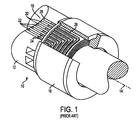
- Figure 1 illustrates a conventional rotor assembly;
- Figure 2 illustrates a perspective view of the rotor assembly of Figure 1, with the retaining ring removed;
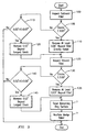
- Figure 3 is a flowchart illustrating a method consistent with the present invention;
- Figure 4 illustrates the formation of an outboard region of a rotor-tooth top consistent with the present invention;
- Figure 5 illustrates the formation of an inboard region of a rotor-tooth top consistent with the present invention;
- Figure 6 illustrates a wedge consistent with the present invention; and,
- Figure 7 illustrates a new or repaired rotor consistent with the present invention.
- Electrical generators utilized in the power-generation industry typically include a rotor with two retaining-ring assemblies like the one illustrated in Figure 1. The
rotor assembly 10 includes arotor 12, aligned for rotation about alongitudinal axis 14 and aretaining ring 16, installed on each end of therotor 12. Therotor 12 includes atooth region 18 with multiplelongitudinal slots 20 defining a plurality oflongitudinal teeth 22.Field windings 24 are disposed between thelongitudinal teeth 22 and within theslots 20. Thefield windings 24 run the length of the rotor and make turns at each end of therotor 12 to form end turns 28. - When the
rotor assembly 10 is spinning, a radially-outward centrifugal force is exerted on thewindings 24 and the end turns 28. In order to retain thefield windings 24 tightly within theslots 20,wedges 26 are positioned in the openings of theslots 20. However, the end turns 28 extend beyond therotor slots 20 and are not retained by these wedges. In order to restrain the end turns 28, a retainingring 16 is installed over each end of therotor 12. The inside diameter of retainingring 16 is formed with an inside diameter that is slightly smaller than the outside diameter of therotor 12. During the manufacturing of therotor assembly 10, the retainingring 16 is heated to expand its inside diameter to facilitate its installation over therotor 12. When the retainingring 16 cools, a shrink fit is created between the retainingring 16 and therotor 12. - Figure 2 illustrates an enlarged perspective view of the
tooth region 18 of Figure 1. The retainingring 16 has been omitted for clarification. As illustrated in Figure 2,windings 24 are restrained bywedges 26 within alongitudinal slot 20 formed betweenadjacent teeth 22. When the rotor assembly is spinning, thewindings 24 andwedge 26 exert a radially-outward force on the tooth tops 23 at the wedge lands 25. The shrink-fitted retaining ring exerts an opposing radially-inward force on thewedge 26 and the retaining-ring lands 28. When the rotor assembly is not spinning (for example, during idle periods), the radially-inward force exerted by the shrink-fitted retaining ring is not balanced by the centrifugal forces exerted on thewedge 26. As a result, the tooth tops 23 tend to be subjected to excessive stresses when a generator is cycled on and off. These stresses tend to form cracks 29 near thefilets 27 of the tooth tops 23. The more frequently a generator is cycled, the more likely such cracks are to form. - Figure 3 illustrates a method of repairing a generator rotor consistent with the present invention. When an electrical generator is disassembled for repair, the outboard sections of the rotor are inspected using a non-destructive test, such as an ultrasonic or eddy-current test, to determine the depth of the stress cracks in the area near the fillets of the tooth top (step 100). If the cracks detected have a maximum depth of less than or equal to about 0.03" (0.0762cm) (decision 105), then at least about 0.06" (0.1524cm) of the outboard-retaining-
ring land 28 is removed beyond the fillet and directly radial by a horizontal mill or othersuitable machining device 400, as illustrated in Figure 4 (step 110). If the cracks detected have a maximum depth of greater than about 0.03" (0.0762cm) and less than about 0.07" (0.1778cm) (decision 115), then about 0.03" (0.0762cm) of the outboard-retaining-ring land 28 is removed beyond the largest crack depth and directly radial, as illustrated in Figure 4 (step 120). If the cracks detected have a maximum depth of greater than about 0.07" (0.1778cm), the method of the present invention may not be suitable for repairing the rotor. - The inboard-retaining-ring land is also inspected using a non-destructive test to determine the depth of the stress cracks in the inboard fillets (step 125). If the cracks detected have a maximum depth of less than or equal to about 0.03" (0.0762cm) (decision 130), then at least about 0.03" (0.0762cm) of rotor material is removed beyond the fillet by a horizontal mill or other suitable machining device 500, as illustrated in Figure 5 (step 135). The fillet may be machined, for example, in an inboard direction for the length of the retaining ring land or beyond the retaining ring land for a short distance. If the cracks detected have a maximum depth of greater than about 0.03" (0.0762cm) and less than about 0.06" (0.1524cm) (decision 140), then about 0.03" (0.0762cm) of rotor material is removed beyond the largest crack depth (step 145). If the cracks detected have a maximum depth of greater than about 0.06" (0.1524cm), the method of the present invention may not be suitable for repairing the rotor.
- In one embodiment of the present invention, the retaining ring lands of the outboard and inboard regions are also machined to form a tapered shrink fit with a height (or radius) that decreases in an inboard direction. The tapered shrink fit interference values vary depending on the rotor diameter, the retaining ring thickness, and the length of the shrink fit. The tapered shrink fit ensures a more uniform stress distribution and minimizes the alternating cyclic fatigue stresses.
- In another embodiment of the present invention, a wedge 600 (illustrated in Figure 6) for use with the rotor may be machined to form
wedge reliefs 610. The wedge reliefs allow the end wedges to have additional radial movement so that the centrifugal load can be transferred fully or partially to the retaining ring at speed. In this way, the rotor tooth top is subjected no load or partial load from the winding in the slot at speed. Typical wedge relief values used are around 0.010" (0.0254cm) to 0.030" (0.0762cm). For rotors with 930 mm outer diameter, a wedge relief of 0.020" (0.0508cm) has been applied over the length of 3.57" (9.068cm) from the end. For a rotor with 1075 mm outer diameter, a wedge relief of 0.020" (0.0508cm) has been applied over the length of 3.75" (9.525cm) from the end. - The features of the improved rotor-tooth top described above may also be incorporated into newly-manufactured rotors to form an improved rotor with an increased resistance to stress-induced cracking. Figure 7 illustrates a new rotor with an improved rotor-
tooth top 30 consistent with the present invention. The improved rotor-tooth top 30 includes an outboard-end section 32 and an inboard-end section 34. The outboard-end section 32 has an enlargedfillet 36 and a substantially radial side-wall 38. The inboard-end section 34 also has an enlargedfillet 40. The dimensions of theenlarged fillet 36 and side-wall 38 in new rotors will vary depending on the dimensions of the rotors. The dimensions of theenlarged fillet 36 and the side-wall 38 in repaired rotors will vary depending upon the dimensions of the rotors and the depth of the stress cracks found during inspection. - The present invention has been described with reference to the accompanying drawings that illustrate preferred embodiments of the invention. The invention may, however, be embodied in many different forms and should not be construed as limited to the embodiments set forth herein. Rather, these embodiments are provided so that this disclosure will be thorough and complete, and will fully convey the scope of the invention to those skilled in the art. Thus, the scope of the invention should be determined based upon the appended claims and their legal equivalents, rather than the specific embodiments described above.
Claims (10)
- A method of repairing a generator rotor having a rotor tooth with a tooth root and a tooth top, said tooth top including an outboard and an inboard region for supporting a retaining ring, wherein said outboard and inboard regions each comprise a retaining-ring land, a wedge land, and a fillet, said method comprising the steps of:(a) inspecting said fillet of said outboard region with a non-destructive testing means to determine the maximum depth cracks in said fillet;(b) when said maximum depth of said cracks in said outboard fillet are less than or equal to about 0.03" (0.0762cm), removing at least about 0.06" (0.1524cm) of material beyond said fillet and directly radial, whereby said wedge land of said outboard region is removed;(c) when said maximum depth of said cracks in said outboard fillet are greater than about 0.03" (0.0762cm) and less than about 0.07" (0.1778cm), removing about 0.03" (0.0762cm) of material beyond said maximum depth of said cracks and directly radial, whereby said wedge land of said outboard region is removed;(d) inspecting said fillet of said inboard region with a non-destructive testing means to determine the maximum depth cracks in said fillet;(e) when said maximum depth of said cracks in said inboard fillet are less than or equal to about 0.03" (0.0762cm), removing at least about 0.03" (0.0762cm) of material beyond said fillet; and(f) when said maximum depth of said cracks in said inboard fillet are greater than about 0.03" (0.0762cm) and less than about 0.06" (0.1524cm), removing about 0.03" (0.0762cm) of material beyond said maximum depth of said cracks.
- The method of claim 1, further comprising the step of
machining said retaining-ring land of said outboard and inboard retaining-ring seats to form a taper having a radius decreasing in the inboard direction. - The method of claim 2, wherein said step of machining said retaining-ring land comprises machining said outboard retaining ring seat to form a first taper having a first slope and machining said inboard retaining ring seat to form a second taper having a second slope.
- The method of any of claims 1 to 3, further comprising the step of
machining a wedge for adaptable for use with said generator rotor by removing approximately 0.02" (0.0508cm) of material from surfaces on said wedge that contact said wedge lands of said tooth top. - The method of claim 4, wherein said step of machining a wedge includes machining said wedge from an outboard end to about 0.5" (1.27cm) past a shrink fit area of said wedge.
- A generator rotor, comprising:a rotor tooth having a tooth root and a tooth top, said tooth top including an outboard and an inboard region for supporting a retaining ring, wherein said outboard and inboard regions each comprise a retaining-ring land, a wedge land, and a fillet,wherein said outboard retaining-ring land has smaller surface area than said inboard retaining-ring land, with substantially radial sidewalls that transitions to a fillet having a radius of about 0.5" (1.27cm), and
wherein said fillet of said inboard region has a compound radius with an upper radius of about 0.125" (0.3175cm) and a lower radius of about 0.063" (0.160cm). - The rotor of claim 6, further comprising
an outboard and inboard retaining-ring having a tapered surface with an increasing the shrink fit interference value in the inboard direction. - The rotor of claim 7, wherein said outboard retaining ring seat has a first taper having a first slope and said inboard retaining ring seat has a second taper having a second slope.
- The rotor of any of claims 6 to 8, further comprising
a wedge adaptable for use with said rotor having a wedge relief of about 0.010" (0.0254cm) to 0.030" (0.0762cm) at the contact surface to the rotor tooth. - The rotor of claim 9, wherein the wedge relief extends from an outboard end of said rotor to about 0.5" (1.27cm) past a shrink fit area of said wedge.
Applications Claiming Priority (2)
| Application Number | Priority Date | Filing Date | Title |
|---|---|---|---|
| US259132 | 2002-09-27 | ||
| US10/259,132 US6941639B2 (en) | 2002-09-27 | 2002-09-27 | Method for repairing generator rotor |
Publications (2)
| Publication Number | Publication Date |
|---|---|
| EP1404009A1 true EP1404009A1 (en) | 2004-03-31 |
| EP1404009B1 EP1404009B1 (en) | 2009-12-30 |
Family
ID=31977896
Family Applications (1)
| Application Number | Title | Priority Date | Filing Date |
|---|---|---|---|
| EP03016992A Expired - Lifetime EP1404009B1 (en) | 2002-09-27 | 2003-07-25 | Rotor and method for repairing the same |
Country Status (3)
| Country | Link |
|---|---|
| US (2) | US6941639B2 (en) |
| EP (1) | EP1404009B1 (en) |
| DE (1) | DE60330739D1 (en) |
Families Citing this family (15)
| Publication number | Priority date | Publication date | Assignee | Title |
|---|---|---|---|---|
| US6941639B2 (en) * | 2002-09-27 | 2005-09-13 | Siemens Westinghouse Power Corporation | Method for repairing generator rotor |
| US7500396B2 (en) * | 2005-10-20 | 2009-03-10 | General Electric Company | Phased array ultrasonic methods and systems for generator rotor teeth inspection |
| US7845076B2 (en) * | 2008-04-21 | 2010-12-07 | General Electric Company | Method for reducing stresses resulting from partial slot dovetail re-machining for generator rotor |
| US7816836B2 (en) * | 2009-01-30 | 2010-10-19 | Honeywell International Inc. | Reduced stress generator pole tip fillet |
| US8481878B2 (en) * | 2009-05-28 | 2013-07-09 | Daniel J. Elliott | Devices and methods related to battery modules |
| US9951621B2 (en) * | 2013-06-05 | 2018-04-24 | Siemens Aktiengesellschaft | Rotor disc with fluid removal channels to enhance life of spindle bolt |
| US9143022B2 (en) | 2013-07-29 | 2015-09-22 | General Electric Company | System and method for rebalancing generator rotor in-situ |
| US9083220B2 (en) | 2013-07-29 | 2015-07-14 | General Electric Company | Method for servicing generator rotor in-situ |
| US9093886B2 (en) | 2013-07-29 | 2015-07-28 | General Electric Company | System and method for rebalancing generator rotor in-situ |
| US10107256B2 (en) | 2013-09-05 | 2018-10-23 | General Electric Company | System for centering wye ring in-situ |
| US9334850B2 (en) | 2013-09-05 | 2016-05-10 | General Electric Company | System and method for centering wye ring in-situ |
| US9488618B2 (en) | 2013-11-05 | 2016-11-08 | Siemens Energy, Inc. | Generator retaining ring and other component thermal degradation evaluation by eddy current non-destructive examination |
| US10103608B2 (en) * | 2015-04-17 | 2018-10-16 | General Electric Company | Generator rotor fretting fatigue crack repair method |
| EP3971565B8 (en) * | 2019-06-14 | 2024-11-06 | Mitsubishi Generator Co., Ltd. | Device for inspecting wedge looseness of rotary electric machine, system for inspecting wedge looseness of rotary electric machine, and method for inspecting wedge looseness of rotary electric machine |
| CN113300510B (en) * | 2021-06-08 | 2022-06-10 | 瑞安市纪龙汽车电器有限公司 | Rotor structure of automobile starter |
Citations (4)
| Publication number | Priority date | Publication date | Assignee | Title |
|---|---|---|---|---|
| EP0298273A1 (en) * | 1987-07-06 | 1989-01-11 | Westinghouse Electric Corporation | Shaft retaining ring |
| US5174011A (en) * | 1991-03-27 | 1992-12-29 | Klaus Weigelt | Method for preparing the rotor of a turbogenerator |
| EP0656681A1 (en) * | 1993-12-03 | 1995-06-07 | Westinghouse Electric Corporation | System and method for reconditioning rotor ends in electrical generators |
| US5883456A (en) * | 1997-10-20 | 1999-03-16 | Siemens Westinghouse Power Corporation | Generator rotor and method for eliminating keyway stress cracks in same |
Family Cites Families (7)
| Publication number | Priority date | Publication date | Assignee | Title |
|---|---|---|---|---|
| US5172475A (en) * | 1991-12-02 | 1992-12-22 | Westinghouse Electric Corp. | Method for repairing a rotor |
| US5861698A (en) * | 1997-03-17 | 1999-01-19 | Westinghouse Electric Corporation | Generator rotor with ring key that reduces tooth top stress |
| US6615470B2 (en) * | 1997-12-15 | 2003-09-09 | General Electric Company | System and method for repairing cast articles |
| US6115917A (en) * | 1998-10-20 | 2000-09-12 | General Electric Company | Single position turbine rotor repair method |
| US6124661A (en) * | 1999-04-08 | 2000-09-26 | Siemens Westinghouse Power Corporation | Generator with retaining ring key that reduces rotor tooth stress |
| US6218756B1 (en) * | 1999-10-28 | 2001-04-17 | Siemens Westinghouse Power Corporation | Generator rotor slot tightening method and associated apparatus |
| US6941639B2 (en) * | 2002-09-27 | 2005-09-13 | Siemens Westinghouse Power Corporation | Method for repairing generator rotor |
-
2002
- 2002-09-27 US US10/259,132 patent/US6941639B2/en not_active Expired - Lifetime
-
2003
- 2003-07-25 DE DE60330739T patent/DE60330739D1/en not_active Expired - Lifetime
- 2003-07-25 EP EP03016992A patent/EP1404009B1/en not_active Expired - Lifetime
-
2005
- 2005-08-04 US US11/197,199 patent/US7122931B2/en not_active Expired - Lifetime
Patent Citations (4)
| Publication number | Priority date | Publication date | Assignee | Title |
|---|---|---|---|---|
| EP0298273A1 (en) * | 1987-07-06 | 1989-01-11 | Westinghouse Electric Corporation | Shaft retaining ring |
| US5174011A (en) * | 1991-03-27 | 1992-12-29 | Klaus Weigelt | Method for preparing the rotor of a turbogenerator |
| EP0656681A1 (en) * | 1993-12-03 | 1995-06-07 | Westinghouse Electric Corporation | System and method for reconditioning rotor ends in electrical generators |
| US5883456A (en) * | 1997-10-20 | 1999-03-16 | Siemens Westinghouse Power Corporation | Generator rotor and method for eliminating keyway stress cracks in same |
Non-Patent Citations (1)
| Title |
|---|
| GARDNER W C: "Generator rotor long ring modifications without rewinds", PROCEEDINGS OF THE 57TH AMERICAN POWER CONFERENCE, vol. 2, 1995, Chicago, USA, pages 1000 - 1004, XP001155376 * |
Also Published As
| Publication number | Publication date |
|---|---|
| US20050264124A1 (en) | 2005-12-01 |
| US20040061403A1 (en) | 2004-04-01 |
| US6941639B2 (en) | 2005-09-13 |
| EP1404009B1 (en) | 2009-12-30 |
| US7122931B2 (en) | 2006-10-17 |
| DE60330739D1 (en) | 2010-02-11 |
Similar Documents
| Publication | Publication Date | Title |
|---|---|---|
| US6941639B2 (en) | Method for repairing generator rotor | |
| EP2535520A2 (en) | Method and apparatus to repair a turbomachine rotor wheel | |
| US11940006B2 (en) | Method for changing a sliding bearing element of a rotor bearing of a wind turbine, and nacelle for a wind turbine | |
| CN101508063A (en) | Method and device for repairing a rotor disk of a gas turbine | |
| EP2722547A1 (en) | Insulated bearing ring | |
| US5883456A (en) | Generator rotor and method for eliminating keyway stress cracks in same | |
| EP0656681B1 (en) | Apparatus and method for reconditioning rotor ends in electrical generators | |
| US7866020B2 (en) | Method for repairing a crack in an electromechanical rotor, method for preventing crack growth in the same, electromechanical rotor and rotary electrical machine | |
| US6022194A (en) | Linear priction welding of steeples and device thereof | |
| US20080030097A1 (en) | Wedge modification and design for maintaining rotor coil slot in a generator | |
| EP2093375A2 (en) | Method of repair for cantilevered stators | |
| WO2006121499A1 (en) | Method of repairing a threaded generator rotor blower assembly | |
| US6124661A (en) | Generator with retaining ring key that reduces rotor tooth stress | |
| AU2006252256B2 (en) | Method for removing a crack in an electromechanical rotor, electromechanical rotor and rotary electrical machine | |
| CN106059209B (en) | Abrasive Fatigue Crack Repair Method for Generator Rotor | |
| US10819196B2 (en) | Electric generators, rotor slot wedges for retaining field coils in slots in rotors of electric generators, and methods of repairing and/or maintaining electric generators and components thereof | |
| JP4834462B2 (en) | Method for removing crack in rotating electric machine rotor, method for preventing crack propagation in rotating electric machine rotor, rotating electric machine rotor and rotating electric machine | |
| US20080278009A1 (en) | Method and apparatus for generator rotor tooth repair | |
| US7513028B2 (en) | Systems and methods for repairing a rotor system keyway | |
| Bonnett | Root cause AC motor failure analysis | |
| WO2014068356A1 (en) | Grooved wedge for rotor | |
| Bailey | Large generator rotor plant life extension-modification base load to multi-start capability | |
| EP1703079A1 (en) | Rotational solid for fixing of blades of a turbo-machine | |
| JPS61258902A (en) | Repairing method for turbine wheel |
Legal Events
| Date | Code | Title | Description |
|---|---|---|---|
| PUAI | Public reference made under article 153(3) epc to a published international application that has entered the european phase |
Free format text: ORIGINAL CODE: 0009012 |
|
| 17P | Request for examination filed |
Effective date: 20031107 |
|
| AK | Designated contracting states |
Kind code of ref document: A1 Designated state(s): AT BE BG CH CY CZ DE DK EE ES FI FR GB GR HU IE IT LI LU MC NL PT RO SE SI SK TR |
|
| AX | Request for extension of the european patent |
Extension state: AL LT LV MK |
|
| 17Q | First examination report despatched |
Effective date: 20040817 |
|
| AKX | Designation fees paid |
Designated state(s): DE FR GB IT |
|
| RAP1 | Party data changed (applicant data changed or rights of an application transferred) |
Owner name: SIEMENS POWER GENERATION, INC. |
|
| RAP1 | Party data changed (applicant data changed or rights of an application transferred) |
Owner name: SIEMENS ENERGY, INC. |
|
| GRAP | Despatch of communication of intention to grant a patent |
Free format text: ORIGINAL CODE: EPIDOSNIGR1 |
|
| GRAS | Grant fee paid |
Free format text: ORIGINAL CODE: EPIDOSNIGR3 |
|
| GRAA | (expected) grant |
Free format text: ORIGINAL CODE: 0009210 |
|
| AK | Designated contracting states |
Kind code of ref document: B1 Designated state(s): DE FR GB IT |
|
| REG | Reference to a national code |
Ref country code: GB Ref legal event code: FG4D |
|
| REF | Corresponds to: |
Ref document number: 60330739 Country of ref document: DE Date of ref document: 20100211 Kind code of ref document: P |
|
| PLBE | No opposition filed within time limit |
Free format text: ORIGINAL CODE: 0009261 |
|
| STAA | Information on the status of an ep patent application or granted ep patent |
Free format text: STATUS: NO OPPOSITION FILED WITHIN TIME LIMIT |
|
| 26N | No opposition filed |
Effective date: 20101001 |
|
| REG | Reference to a national code |
Ref country code: FR Ref legal event code: PLFP Year of fee payment: 14 |
|
| REG | Reference to a national code |
Ref country code: FR Ref legal event code: PLFP Year of fee payment: 15 |
|
| PGFP | Annual fee paid to national office [announced via postgrant information from national office to epo] |
Ref country code: IT Payment date: 20170726 Year of fee payment: 15 |
|
| REG | Reference to a national code |
Ref country code: FR Ref legal event code: PLFP Year of fee payment: 16 |
|
| PG25 | Lapsed in a contracting state [announced via postgrant information from national office to epo] |
Ref country code: IT Free format text: LAPSE BECAUSE OF NON-PAYMENT OF DUE FEES Effective date: 20180725 |
|
| PGFP | Annual fee paid to national office [announced via postgrant information from national office to epo] |
Ref country code: GB Payment date: 20220823 Year of fee payment: 20 Ref country code: DE Payment date: 20220617 Year of fee payment: 20 |
|
| PGFP | Annual fee paid to national office [announced via postgrant information from national office to epo] |
Ref country code: FR Payment date: 20220721 Year of fee payment: 20 |
|
| REG | Reference to a national code |
Ref country code: DE Ref legal event code: R082 Ref document number: 60330739 Country of ref document: DE Representative=s name: ROTH, THOMAS, DIPL.-PHYS. DR., DE |
|
| REG | Reference to a national code |
Ref country code: DE Ref legal event code: R071 Ref document number: 60330739 Country of ref document: DE |
|
| REG | Reference to a national code |
Ref country code: GB Ref legal event code: PE20 Expiry date: 20230724 |
|
| PG25 | Lapsed in a contracting state [announced via postgrant information from national office to epo] |
Ref country code: GB Free format text: LAPSE BECAUSE OF EXPIRATION OF PROTECTION Effective date: 20230724 |