EP1403989A1 - Electrical cabinet made of panel elements - Google Patents
Electrical cabinet made of panel elements Download PDFInfo
- Publication number
- EP1403989A1 EP1403989A1 EP03077946.6A EP03077946A EP1403989A1 EP 1403989 A1 EP1403989 A1 EP 1403989A1 EP 03077946 A EP03077946 A EP 03077946A EP 1403989 A1 EP1403989 A1 EP 1403989A1
- Authority
- EP
- European Patent Office
- Prior art keywords
- sub
- folded
- cabinet
- structures
- flat
- Prior art date
- Legal status (The legal status is an assumption and is not a legal conclusion. Google has not performed a legal analysis and makes no representation as to the accuracy of the status listed.)
- Granted
Links
- 230000008878 coupling Effects 0.000 claims description 34
- 238000010168 coupling process Methods 0.000 claims description 34
- 238000005859 coupling reaction Methods 0.000 claims description 34
- 238000004519 manufacturing process Methods 0.000 description 5
- 238000000034 method Methods 0.000 description 4
- 238000009434 installation Methods 0.000 description 3
- 238000010276 construction Methods 0.000 description 2
- 239000007787 solid Substances 0.000 description 2
- 230000002860 competitive effect Effects 0.000 description 1
- 238000005520 cutting process Methods 0.000 description 1
- 238000009826 distribution Methods 0.000 description 1
- 230000005520 electrodynamics Effects 0.000 description 1
Images




Classifications
-
- H—ELECTRICITY
- H02—GENERATION; CONVERSION OR DISTRIBUTION OF ELECTRIC POWER
- H02B—BOARDS, SUBSTATIONS OR SWITCHING ARRANGEMENTS FOR THE SUPPLY OR DISTRIBUTION OF ELECTRIC POWER
- H02B1/00—Frameworks, boards, panels, desks, casings; Details of substations or switching arrangements
- H02B1/26—Casings; Parts thereof or accessories therefor
- H02B1/30—Cabinet-type casings; Parts thereof or accessories therefor
Definitions
- the present invention refers to a cabinets structure for electric switchboards and to electric switchboards which use such structure; this invention especially refers to a cabinets structure for electric switchboards in which the structural elements that form the cabinet are properly configurated to facilitate the assembling, according to a particularly efficient solution as far as praticality of use and production are concerned.
- the cabinets for electric switchboards are designed and realised in order to satisfy the specific functional requirements of the components that form the cabinet.
- the electric switchboards use a system of parallel metallic bars, each of them is connected with a corresponding phase of the electric feeding system.
- the bars are electrically connected with the devices used in the switchboard, for example the circuit breakers, and are geometrically coupled with proper isolating and supporting devices.
- Such isolating and supporting devices besides electrically isolating the bars, allow their connection to the cabinet structure. In this way, the electrodynamic forces generated by the current flowing in the bars are discharged on the cabinet structure, which must have consequently proper characteristic of structural resistence.
- the electric devices are placed on one or more fixing guides, connected to the cabinet frame directly or through proper additional connecting elements.
- the cabinets In order to satisfy such requirements, the cabinets generally have a parallelepiped structure, inside of which is defmed a proper volume in order to place the different switchboard components and whose frame allows the fixing of the supporting elements of such components, of the isolating panels and of the cabinet door.
- the frame is generally made up of two sub-structures of generally rectangular shape, that form respectively the lower and upper basis of the parallelepiped structure.
- Such sub-structures are generally made up of four angular elements, normally three-way joints, which are mutually connected through section bars placed in a substantially horizontal position and form the sides of the basic rectangle.
- the two sub-structure are mutually connected on their turn through vertical section bars, so called posts, each of them being connected, in correspondence with its ends, to two angular elements.
- a number of holes are normally positioned along the vertical posts for the direct fixing of the supporting elements of the electric devices and of the distribution bars or for the fixing of intermediate transversal elements, with which such supporting elements are connected.
- the assembling methods of the different elements forming the cabinet are not fully satisfying, in particular as far as number and shape of the requested components in order to realise the sub-structure is concerned. Furthermore, the high amount of existing connections requires to use a much higher number of fixing elements, such for example screws, bolts and similar.
- the assembling procedure given the high amount of components and connections, requires relatively long working period and/or the employment of at least two workers with consequent increase of the final installation costs.
- Main aim of the present invention is to provide a cabinets structure for electric switchboards, which allows the reduction of the number of necessary components with consequent advantages for the production.
- one of the scopes is to realise a cabinet structure for electric switchboards, in which the connection among the different elements forming the structure is of easy construction, facilitating then the assembling and reducing the production time.
- Another important scope is to realise a cabinet structure for electric switchboards in which the number of fixing elements is reduced, consequently reducing the amount of corresponding fixing procedures as well.
- Not last aim of this invention is to realise a cabinets structure of high reliability, relatively easy to produce and with competitive costs.
- a cabinet structure for electric switchboards said cabinet having a first rear wall, a second and a third wall respectively superior and inferior, a fourth and a fifth sidewalls and a sixth front wall, such walls defining an internal volume, able to contain one or more electric devices.
- the cabinet structure for electric switchboards according to the invention is characterised in that it includes:
- the cabinet structure for electric switchboards has therefore a completely innovative configuration, in particular for what concerns for example the vertical posts, which are integrated in the structure of the sidewalls and/or rear wall, allowing their direct coupling.
- a cabinet for electric switchboards generally presents a first rear walls 1, a second and a third wall respectively superior 2 and inferior 3, a fourth and a fifth sidewalls (4 and 5) and a sixth front wall 6.
- Such walls define then an interior volume able to contain one or more electric devices.
- rear and front superior and inferior, and lateral refer to the condition of normal installation of the electric switchboards and to the corresponding access modalities for a worker, referring with front to the wall in which it is placed the access door to the switchboard and from which the users have access to the switchboard and to the corresponding devices.
- the cabinet structure for electric switchboards includes a first rear sub-structure 10 of substantially rectangular shape, with four edges 11, 12, 13 and 14, at least two of such edges being folded in order to form proper coupling profiles. Coupling means 100 are then placed in correspondence with the angles of such first sub-structure 10.
- the cabinet structure according to the invention present a second and a third sub-structure, respectively superior 20 and inferior 30.
- Each of such second and third sub-structure includes a first flat wall 21 and 31 of substantially rectangular shape. At least two edges of the first flat wall are folded in order to form proper coupling profiles.
- each of this fourth and fifth sub-structure 40, 50 including a second flat wall of substantially rectangular shape, referred to respectively with the reference numbers 41 and 51. At least one edge of the second flat wall is folded in order to form a proper coupling profile; furthermore, coupling means 100 are placed in correspondence with the ends of the folded edge.
- the fourth and fifth lateral sub-structures include then first link means 42 and 52 properly placed on them. These link means can be coupled with corresponding link means placed on the sixth front sub-structure (not shown in the figure).
- the sixth front sub-structure is a door of substantially rectangular shape and the link means consists of the system of hinges, handle and door lock, which allow the door opening and closing.
- the two lateral edges 11 and 12 of the first sub-structure 10 are folded to the interior and form a profile with three flat surfaces 110, 111 and 112.
- the first 110 and the second 111 of these three surfaces define a volume able to contain the coupling means, as clearly shown in figure 3.
- the second 11 and third 112 of such three surfaces define on the contrary the coupling profile of the first sub-structure 10 with the fourth 40 and the fifth 50 lateral sub-structures.
- the walls 110 and 112 are substantially parallel one to another and substantially perpendicular to the wall 111 and to the lying plane of the sub-structure 10.
- At least one portion of the superior 13 and inferior 14 edges of the first sub-structure 10 are folded to the interior defining a flat surface 131 and 141, able to couple respectively with the second 20 and third 30 sub-structure.
- the surfaces 131 and 141 are generally perpendicular to the lying plane of the sub-structure 10.
- each lateral edge 22, 23 and 32, 33 of the first flat wall 21 and 31 of the second and third sub-structure 20 and 30, is folded to the interior and forms a profile with three flat surfaces.
- the first 331 and the second 332 of such three flat surfaces define a volume able to contain the coupling means 100, while the second 332 and the third 333 of such three flat surfaces define the coupling profile of such second and third sub-structures with such fourth and fifth lateral sub-structures.
- the walls 331 and 333 are substantially parallel each other and substantially perpendicular to the wall 332 and to the lying plane of the flat surface 31. Similar structure, not shown in detail in figure, is realised in correspondence with the edges 22, 23 and 32.
- At least a portion of the superior edge 24, 34 of such first flat wall is folded to the interior according to a step profile defining a flat surface able to couple with such first sub-structure 10.
- the step profile on the rear edge 24 couples with the flat surface 131 on the superior edge 13 of the first sub-structure 10, while the step profile on the rear edge 34 couples with the flat surface 141 defined on the inferior edge 14 of the first sub-structure 10.
- 34 is defined at least one or more slots (not shown in the figure) able to engage with corresponding protrusions 132 and 142 defined on the superior 13 and inferior 14 edges of such first sub-structure, in correspondence with the flat surfaces 131 and 141, respectively.
- the first flat surface 21, 31 can be continuous or can have one or more holes 300 of different shapes and dimensions, as represented in the figures.
- the front edge 43, 53 of the second flat wall 41, 51 of the fourth and fifth sub-structure 40, 50 is folded to the interior according to a step profile having a first flat surface 431, 531.
- the flat surface 431, 531 defines a housing area for the coupling means 100.
- the step profile has furthermore a second flat surface 432, 532 of coupling with the sixth sub-structure.
- the first link means are placed in correspondence with the first flat surface 431, 531.
- the rear edge 44, 54 of such second flat wall 41, 51 is folded to the interior, defining a flat surface substantially perpendicular to the wall 41, 51, for example the surface defined with the reference number 441 of figure 5, of coupling with such first sub-structure, and in particular with the surface 111, placed in correspondence with the lateral edge 11 of the first sub-structure 10.
- the assembling is facilitated by the fact that the basis of the sub-structures 40 and 50 lies on the flat surface 332 and 322 of the third sub-structure 30; furthermore, the flat wall 41 couples with the flat surface 323 of the third sub-structure 30 and with the corresponding surface (not shown in the figure) of the second sub-structure 20, while the flat wall 51 couples with the flat surface 333 of the third sub-structure 30 and with the corresponding surface (not shown in the figure) of the second sub-structure 20.
- the coupling means 100 preferably include angular joints having an L-shaped body which has a central portion 101 and two lateral portions 102 and 103, each of them being substantially shaped as parallelepiped. As clearly shown in the figures, the lateral portions 102,103 of the angular joints engage in the spaces defined by the profiled edges of the different sub-structures, allowing a solid and at the same time rapid assembling.
- the fixing of the structure can be realised wit proper means, for example through holes 104 on the angular joints and/or holes 200 in proper areas of the different sub-structures, in which screws or other fixing systems engage.
- the assembling is particularly fast, as consequence of the reduced amount of components and of the low number of connections, reducing then time and costs of installation charged to the final user.
- the cabinet structure according to the invention is sufficiently solid, since the particular structure of the different sub-structures, and in particular of the different section edges, gives proper mechanic stability.
- the presence of proper coupling means, for example angular joints contributes to solidity, without the necessity of vertical posts of particular structure.
Landscapes
- Engineering & Computer Science (AREA)
- Power Engineering (AREA)
- Patch Boards (AREA)
- Casings For Electric Apparatus (AREA)
Abstract
Description
- The present invention refers to a cabinets structure for electric switchboards and to electric switchboards which use such structure; this invention especially refers to a cabinets structure for electric switchboards in which the structural elements that form the cabinet are properly configurated to facilitate the assembling, according to a particularly efficient solution as far as praticality of use and production are concerned.
- Generally, the cabinets for electric switchboards are designed and realised in order to satisfy the specific functional requirements of the components that form the cabinet. As it is known, the electric switchboards use a system of parallel metallic bars, each of them is connected with a corresponding phase of the electric feeding system. Inside the cabinet, the bars are electrically connected with the devices used in the switchboard, for example the circuit breakers, and are geometrically coupled with proper isolating and supporting devices. Such isolating and supporting devices, besides electrically isolating the bars, allow their connection to the cabinet structure. In this way, the electrodynamic forces generated by the current flowing in the bars are discharged on the cabinet structure, which must have consequently proper characteristic of structural resistence. Furthermore, the electric devices are placed on one or more fixing guides, connected to the cabinet frame directly or through proper additional connecting elements.
- In order to satisfy such requirements, the cabinets generally have a parallelepiped structure, inside of which is defmed a proper volume in order to place the different switchboard components and whose frame allows the fixing of the supporting elements of such components, of the isolating panels and of the cabinet door.
- In particular, the frame is generally made up of two sub-structures of generally rectangular shape, that form respectively the lower and upper basis of the parallelepiped structure. Such sub-structures are generally made up of four angular elements, normally three-way joints, which are mutually connected through section bars placed in a substantially horizontal position and form the sides of the basic rectangle. The two sub-structure are mutually connected on their turn through vertical section bars, so called posts, each of them being connected, in correspondence with its ends, to two angular elements. A number of holes are normally positioned along the vertical posts for the direct fixing of the supporting elements of the electric devices and of the distribution bars or for the fixing of intermediate transversal elements, with which such supporting elements are connected.
- At the present state of the art, the assembling methods of the different elements forming the cabinet, although having the advantages of a modular construction, are not fully satisfying, in particular as far as number and shape of the requested components in order to realise the sub-structure is concerned. Furthermore, the high amount of existing connections requires to use a much higher number of fixing elements, such for example screws, bolts and similar.
- The assembling procedure, given the high amount of components and connections, requires relatively long working period and/or the employment of at least two workers with consequent increase of the final installation costs.
- It is evident from what above described, that at the present level of the art there is the necessity to have cabinets structures for electric switchboards which represent a valid alternative to the above described solutions.
- Main aim of the present invention is to provide a cabinets structure for electric switchboards, which allows the reduction of the number of necessary components with consequent advantages for the production.
- Within this aim, one of the scopes is to realise a cabinet structure for electric switchboards, in which the connection among the different elements forming the structure is of easy construction, facilitating then the assembling and reducing the production time.
- Another important scope is to realise a cabinet structure for electric switchboards in which the number of fixing elements is reduced, consequently reducing the amount of corresponding fixing procedures as well.
- Not last aim of this invention is to realise a cabinets structure of high reliability, relatively easy to produce and with competitive costs.
- This aim, as well as these and other scopes which will better emerge afterwards, are obtained with a cabinet structure for electric switchboards, said cabinet having a first rear wall, a second and a third wall respectively superior and inferior, a fourth and a fifth sidewalls and a sixth front wall, such walls defining an internal volume, able to contain one or more electric devices. The cabinet structure for electric switchboards according to the invention is characterised in that it includes:
- a first sub-structure of substantially rectangular shape, at least two edges of such first sub-structure being folded in order to form proper coupling profiles, coupling means being placed in correspondence with the angles of such first sub-structure;
- a second and a third sub-structure, respectively superior and inferior, each of them including a first flat wall of substantially rectangular shape, at least two edges of such first flat wall being folded in order to build proper coupling profiles;
- a fourth and a fifth lateral sub-structures, each of them including a second flat wall of substantially rectangular shape, at least an edge of such second flat wall being folded in order to form a proper coupling profile, coupling means being placed in correspondence with the ends of such at least a folded edge, each of these fourth and fifth lateral sub-structures including first link means properly placed on them;
- a sixth front sub-structure of substantially rectangular shape, which includes second link means, which can be coupled with such first link means,
- The cabinet structure for electric switchboards according to the invention, has therefore a completely innovative configuration, in particular for what concerns for example the vertical posts, which are integrated in the structure of the sidewalls and/or rear wall, allowing their direct coupling.
- Further characteristics and advantages of the invention will better emerge from the description of favourite but not limiting embodiments of a cabinet structure for electric switchboards according to the invention, represented as non-limiting examples in the attached drawings, in which:
- figure 1 is a perspective view of a cabinet for electric switchboards realised by assembling a structure according to the invention;
- figure 2 is a perspective view of the rear sub-structure of a cabinet for electric switchboards according to the invention;
- figure is a perspective view of a detail of the sub-structure shown in figure 2;
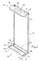
- figure 4 is a perspective view of the rear sub-structure and of the sub-structures superior and inferior of a cabinet for electric switchboards according to the invention;
- figure 5 is a perspective view of the rear, superior, inferior and lateral sub-structures of a cabinet for electric switchboards according to the invention.
- The structure of a cabinet for electric switchboards according to the invention will be described with reference to the above mentioned figures, without limiting in any way its application. In the figures, the same reference number refers to similar components.
- With reference to figure 1, a cabinet for electric switchboards generally presents a first
rear walls 1, a second and a third wall respectively superior 2 and inferior 3, a fourth and a fifth sidewalls (4 and 5) and asixth front wall 6. Such walls define then an interior volume able to contain one or more electric devices. - The terms rear and front superior and inferior, and lateral refer to the condition of normal installation of the electric switchboards and to the corresponding access modalities for a worker, referring with front to the wall in which it is placed the access door to the switchboard and from which the users have access to the switchboard and to the corresponding devices.
- With reference to figures 2 and 3, the cabinet structure for electric switchboards according to the invention includes a first
rear sub-structure 10 of substantially rectangular shape, with fouredges first sub-structure 10. - With reference to figure 4, the cabinet structure according to the invention present a second and a third sub-structure, respectively superior 20 and inferior 30. Each of such second and third sub-structure includes a first
flat wall - In figure 5 the fourth 40 and fifth 50 lateral sub-structure of the structure according to the invention are represented, each of this fourth and
fifth sub-structure reference numbers - The fourth and fifth lateral sub-structures include then first link means 42 and 52 properly placed on them. These link means can be coupled with corresponding link means placed on the sixth front sub-structure (not shown in the figure). In practice, the sixth front sub-structure is a door of substantially rectangular shape and the link means consists of the system of hinges, handle and door lock, which allow the door opening and closing.
- Preferably, the two
lateral edges first sub-structure 10 are folded to the interior and form a profile with threeflat surfaces first sub-structure 10 with the fourth 40 and the fifth 50 lateral sub-structures. Advantageously, thewalls wall 111 and to the lying plane of thesub-structure 10. - Advantageously, and with particular reference to figure 3, at least one portion of the superior 13 and inferior 14 edges of the
first sub-structure 10 are folded to the interior defining aflat surface surfaces sub-structure 10. - With reference to figures 4 and 5, preferably at least one portion of each
lateral edge flat wall third sub-structure edge 33 of thefirst wall 31, the first 331 and the second 332 of such three flat surfaces define a volume able to contain the coupling means 100, while the second 332 and the third 333 of such three flat surfaces define the coupling profile of such second and third sub-structures with such fourth and fifth lateral sub-structures. Advantageously, thewalls wall 332 and to the lying plane of theflat surface 31. Similar structure, not shown in detail in figure, is realised in correspondence with theedges - Furthermore, according to a further preferred embodiment, at least a portion of the
superior edge first sub-structure 10. In particular, the step profile on therear edge 24 couples with theflat surface 131 on thesuperior edge 13 of thefirst sub-structure 10, while the step profile on therear edge 34 couples with theflat surface 141 defined on theinferior edge 14 of thefirst sub-structure 10. - Preferably, on the step profile on the
rear edge corresponding protrusions 132 and 142 defined on the superior 13 and inferior 14 edges of such first sub-structure, in correspondence with theflat surfaces - The first
flat surface more holes 300 of different shapes and dimensions, as represented in the figures. - With reference to figure 5, the
front edge flat wall fifth sub-structure flat surface flat surface flat surface flat surface - Advantageously, the
rear edge flat wall wall reference number 441 of figure 5, of coupling with such first sub-structure, and in particular with thesurface 111, placed in correspondence with thelateral edge 11 of thefirst sub-structure 10. - The assembling is facilitated by the fact that the basis of the
sub-structures flat surface third sub-structure 30; furthermore, theflat wall 41 couples with theflat surface 323 of thethird sub-structure 30 and with the corresponding surface (not shown in the figure) of thesecond sub-structure 20, while theflat wall 51 couples with theflat surface 333 of thethird sub-structure 30 and with the corresponding surface (not shown in the figure) of thesecond sub-structure 20. - The coupling means 100 preferably include angular joints having an L-shaped body which has a
central portion 101 and twolateral portions - The fixing of the structure can be realised wit proper means, for example through
holes 104 on the angular joints and/orholes 200 in proper areas of the different sub-structures, in which screws or other fixing systems engage. - It has been shown how the cabinet structure for electric switchboards according to the invention completely fulfils the intended aim and scopes. It has been shown that the use of the different sub-structures that form the cabinet structure, allows to considerably improve the production time of the single pieces, because it is possible to obtain the different sub-structures through relatively simple and fast procedures of sheets cutting and folding. Given the modularity and symmetry of the structure, the different components amount is reduced, reducing then the number of production cycles necessary to produce the different types of sub-structures.
- The assembling is particularly fast, as consequence of the reduced amount of components and of the low number of connections, reducing then time and costs of installation charged to the final user. The cabinet structure according to the invention is sufficiently solid, since the particular structure of the different sub-structures, and in particular of the different section edges, gives proper mechanic stability. The presence of proper coupling means, for example angular joints contributes to solidity, without the necessity of vertical posts of particular structure.
- The cabinet structure so conceived is susceptible of various changes and variations, all belonging to the field of this invention; furthermore all the details can be substituted by others technically equivalent.
Claims (12)
- A cabinet structure for electric switchboards, said cabinet having a first rear wall, a second and a third wall respectively superior and inferior, a fourth and a fifth sidewalls and a sixth front wall, said walls defining an internal volume able to contain one or more electric devices, characterised in that is includes:- a first sub-structure with substantially rectangular shape, at least two edges of such first sub-structure being folded to form proper coupling profiles, coupling means being furthermore placed in correspondence with the angles of such first sub-structure;- a second and a third sub-structures, respectively superior and inferior, each of said second and third sub-structures including one first flat wall with substantially rectangular shape, at least two edges of said first flat wall being folded to form proper coupling profiles;- a fourth and a fifth lateral sub-structures, each of such fourth and fifth sub-structures including a second flat wall of substantially rectangular shape, at least one edge of said second flat wall being folded to form a proper coupling profile, coupling means being placed in correspondence with the ends of such at least a folded edge, each of said fourth and fifth lateral sub-structures including first link means properly placed on them;- a sixth front sub-structure of substantially rectangular shape including second link means which can be coupled with such first link means,said first, second, third, fourth and fifth sub-structures being directly coupled one to another.
- Cabinet structure for electric switchboards according to claim 1, characterised in that the two lateral edges of said first sub-structure are folded to the interior building a profile with three flat surfaces, the first and second of them defining a volume able to contain said coupling means, the second and the third of these three surfaces defining the coupling profile of said first sub-structure with said fourth and fifth lateral sub-structures.
- Cabinet structure for electric switchboards according to any one of the previous claims, characterised in that at least a portion of the superior and inferior edges of said first sub-structure is folded to the interior, defining a flat surface able to couple with said second and third sub-structure.
- Cabinet structure for electric switchboards according to any one of the previous claims, characterised in that at least a portion of each lateral edge of said first wall is folded to the interior forming a profile with three flat surfaces, the first and the second of said three surfaces plane defining a volume able to contain said coupling means, the second and third of said three surfaces defining the coupling profile of said second and third sub-structures with said fourth and fifth lateral sub-structures.
- Cabinet structure for electric switchboards according to any one of the previous claims, characterised in that at least a portion of the rear edge of said first flat wall is folded to the interior according to a step profile, defining a flat surface able to couple with said first sub-structure.
- Cabinet structure for electric switchboards according to claim 5, characterised in that on said step profile is defined at least a crack able to engage with a corresponding jut defined on the superior and inferior edges of said first sub-structure.
- Cabinet structure for electric switchboards according to any one of the previous claims, characterised in that the front edge of said second flat wall is folded to the interior according to a step profile having a first flat surface which defines a housing area for said coupling means and a second flat surface with said sixth sub-structure.
- Cabinet structure for electric switchboards according to any one of the previous claims, characterised in that the rear edge of said second flat wall is folded to the interior, defining a flat coupling surface with said first sub-structure.
- Cabinet structure for electric switchboards according any one of the previous claims, characterised in that said coupling means include angular joints having a body shaped as L which has a central portion and two lateral portions, each of them being substantially shaped as parallelepiped.
- Cabinet structure for electric switchboards according any one of the previous claims, characterised in that said coupling means include fixing means.
- Cabinet structure for electric switchboards according any one of the previous claims, characterised in that fixing means are placed in correspondence with one or more coupling profiles.
- An electric switchboard, including a cabinet structure according to any one of the previous claims.
Applications Claiming Priority (2)
| Application Number | Priority Date | Filing Date | Title |
|---|---|---|---|
| IT000028A ITBG20020028A1 (en) | 2002-09-26 | 2002-09-26 | CABINET STRUCTURE FOR ELECTRICAL PANELS. |
| ITBG20020028 | 2002-09-26 |
Publications (2)
| Publication Number | Publication Date |
|---|---|
| EP1403989A1 true EP1403989A1 (en) | 2004-03-31 |
| EP1403989B1 EP1403989B1 (en) | 2017-11-08 |
Family
ID=29266877
Family Applications (1)
| Application Number | Title | Priority Date | Filing Date |
|---|---|---|---|
| EP03077946.6A Expired - Lifetime EP1403989B1 (en) | 2002-09-26 | 2003-09-18 | Electrical cabinet made of panel elements |
Country Status (4)
| Country | Link |
|---|---|
| EP (1) | EP1403989B1 (en) |
| EG (1) | EG25284A (en) |
| ES (1) | ES2657758T3 (en) |
| IT (1) | ITBG20020028A1 (en) |
Cited By (2)
| Publication number | Priority date | Publication date | Assignee | Title |
|---|---|---|---|---|
| CN108063370A (en) * | 2017-12-26 | 2018-05-22 | 出惠玲 | A kind of indoor transformer cabinet |
| CN112701575A (en) * | 2020-11-30 | 2021-04-23 | 国网山东省电力公司青岛供电公司 | Secondary screen cabinet and method of relay protection device |
Citations (3)
| Publication number | Priority date | Publication date | Assignee | Title |
|---|---|---|---|---|
| EP0577140A2 (en) * | 1992-07-02 | 1994-01-05 | Eberhard Gawehn | Switch cabinet |
| US6209976B1 (en) * | 1999-06-21 | 2001-04-03 | Frank Shear | Cabinet box |
| DE10104214A1 (en) * | 2001-01-31 | 2002-08-01 | Haendler Gmbh & Co Kg Elektro | Construction of electrical cabinet holds corner frame section in clamping arrangement with back wall and side sections |
-
2002
- 2002-09-26 IT IT000028A patent/ITBG20020028A1/en unknown
-
2003
- 2003-09-18 EP EP03077946.6A patent/EP1403989B1/en not_active Expired - Lifetime
- 2003-09-18 ES ES03077946.6T patent/ES2657758T3/en not_active Expired - Lifetime
- 2003-09-24 EG EG2003090948A patent/EG25284A/en active
Patent Citations (3)
| Publication number | Priority date | Publication date | Assignee | Title |
|---|---|---|---|---|
| EP0577140A2 (en) * | 1992-07-02 | 1994-01-05 | Eberhard Gawehn | Switch cabinet |
| US6209976B1 (en) * | 1999-06-21 | 2001-04-03 | Frank Shear | Cabinet box |
| DE10104214A1 (en) * | 2001-01-31 | 2002-08-01 | Haendler Gmbh & Co Kg Elektro | Construction of electrical cabinet holds corner frame section in clamping arrangement with back wall and side sections |
Cited By (2)
| Publication number | Priority date | Publication date | Assignee | Title |
|---|---|---|---|---|
| CN108063370A (en) * | 2017-12-26 | 2018-05-22 | 出惠玲 | A kind of indoor transformer cabinet |
| CN112701575A (en) * | 2020-11-30 | 2021-04-23 | 国网山东省电力公司青岛供电公司 | Secondary screen cabinet and method of relay protection device |
Also Published As
| Publication number | Publication date |
|---|---|
| ITBG20020028A0 (en) | 2002-09-12 |
| EP1403989B1 (en) | 2017-11-08 |
| ITBG20020028A1 (en) | 2004-03-27 |
| EG25284A (en) | 2011-12-05 |
| ES2657758T3 (en) | 2018-03-06 |
Similar Documents
| Publication | Publication Date | Title |
|---|---|---|
| EP1243058B1 (en) | Supporting frame for a cabinet of an electrical panel | |
| US4988008A (en) | Supporting framework for a control cabinet | |
| US8128183B2 (en) | Rack system | |
| RU2006115564A (en) | IMPROVED METAL DESIGN FOR MANUFACTURING ELECTRICAL DISTRIBUTION CABINETS / BOARDS | |
| US7209343B2 (en) | Adjustable riser and panel board incorporating same | |
| RU2400888C2 (en) | Frame structure for distribution cabinet, distribution cabinet and allied components therefor | |
| CN103457171B (en) | Cabinet for an electrical switchboard | |
| WO2001001533A1 (en) | Frame structure for an enclosure for electrical equipment | |
| EP1403989B1 (en) | Electrical cabinet made of panel elements | |
| EP1243057B1 (en) | Cabinet of an electrical panel | |
| KR100805392B1 (en) | Booth bar fixing holder for distribution panel | |
| PL182885B1 (en) | Storage system | |
| EP0399595A1 (en) | Sectional container for electrical boards assembled with joints | |
| EP1897465B1 (en) | Manufacturing method for metal cabinets | |
| EP2242155B1 (en) | Corner structure for electrical enclosure | |
| JP2002319778A (en) | Electrical and electronic equipment storage cabinet frame | |
| CN211508273U (en) | Power distribution cabinet mounting structure | |
| EP1884001B1 (en) | Cabinet for electrical switchboard | |
| RU164504U1 (en) | SWITCHBOARD CABINET | |
| EP1366549A1 (en) | Device for connecting and grounding frame components in electrical switchboards | |
| AU2009251102B2 (en) | A Gland Plate Connection System | |
| CN216291897U (en) | Inside mounting structure of control cabinet | |
| CN216672224U (en) | Power distribution cabinet convenient to disassemble and assemble | |
| AU2006319764B2 (en) | Frame member for a switching cabinet rack | |
| EP2136446B1 (en) | Structural member usable to make up the framework of switchboard cubicle. |
Legal Events
| Date | Code | Title | Description |
|---|---|---|---|
| PUAI | Public reference made under article 153(3) epc to a published international application that has entered the european phase |
Free format text: ORIGINAL CODE: 0009012 |
|
| AK | Designated contracting states |
Kind code of ref document: A1 Designated state(s): AT BE BG CH CY CZ DE DK EE ES FI FR GB GR HU IE IT LI LU MC NL PT RO SE SI SK TR |
|
| AX | Request for extension of the european patent |
Extension state: AL LT LV MK |
|
| 17P | Request for examination filed |
Effective date: 20040920 |
|
| AKX | Designation fees paid |
Designated state(s): AT BE BG CH CY CZ DE DK EE ES FI FR GB GR HU IE IT LI LU MC NL PT RO SE SI SK TR |
|
| RAP1 | Party data changed (applicant data changed or rights of an application transferred) |
Owner name: ABB S.P.A. |
|
| 17Q | First examination report despatched |
Effective date: 20160506 |
|
| GRAP | Despatch of communication of intention to grant a patent |
Free format text: ORIGINAL CODE: EPIDOSNIGR1 |
|
| INTG | Intention to grant announced |
Effective date: 20170404 |
|
| GRAJ | Information related to disapproval of communication of intention to grant by the applicant or resumption of examination proceedings by the epo deleted |
Free format text: ORIGINAL CODE: EPIDOSDIGR1 |
|
| GRAP | Despatch of communication of intention to grant a patent |
Free format text: ORIGINAL CODE: EPIDOSNIGR1 |
|
| INTC | Intention to grant announced (deleted) | ||
| INTG | Intention to grant announced |
Effective date: 20170811 |
|
| GRAS | Grant fee paid |
Free format text: ORIGINAL CODE: EPIDOSNIGR3 |
|
| GRAA | (expected) grant |
Free format text: ORIGINAL CODE: 0009210 |
|
| AK | Designated contracting states |
Kind code of ref document: B1 Designated state(s): AT BE BG CH CY CZ DE DK EE ES FI FR GB GR HU IE IT LI LU MC NL PT RO SE SI SK TR |
|
| REG | Reference to a national code |
Ref country code: GB Ref legal event code: FG4D |
|
| REG | Reference to a national code |
Ref country code: CH Ref legal event code: EP Ref country code: AT Ref legal event code: REF Ref document number: 945029 Country of ref document: AT Kind code of ref document: T Effective date: 20171115 |
|
| REG | Reference to a national code |
Ref country code: IE Ref legal event code: FG4D |
|
| REG | Reference to a national code |
Ref country code: DE Ref legal event code: R096 Ref document number: 60350764 Country of ref document: DE |
|
| REG | Reference to a national code |
Ref country code: SE Ref legal event code: TRGR |
|
| REG | Reference to a national code |
Ref country code: ES Ref legal event code: FG2A Ref document number: 2657758 Country of ref document: ES Kind code of ref document: T3 Effective date: 20180306 |
|
| REG | Reference to a national code |
Ref country code: NL Ref legal event code: MP Effective date: 20171108 |
|
| REG | Reference to a national code |
Ref country code: AT Ref legal event code: MK05 Ref document number: 945029 Country of ref document: AT Kind code of ref document: T Effective date: 20171108 |
|
| PG25 | Lapsed in a contracting state [announced via postgrant information from national office to epo] |
Ref country code: NL Free format text: LAPSE BECAUSE OF FAILURE TO SUBMIT A TRANSLATION OF THE DESCRIPTION OR TO PAY THE FEE WITHIN THE PRESCRIBED TIME-LIMIT Effective date: 20171108 Ref country code: FI Free format text: LAPSE BECAUSE OF FAILURE TO SUBMIT A TRANSLATION OF THE DESCRIPTION OR TO PAY THE FEE WITHIN THE PRESCRIBED TIME-LIMIT Effective date: 20171108 |
|
| PG25 | Lapsed in a contracting state [announced via postgrant information from national office to epo] |
Ref country code: GR Free format text: LAPSE BECAUSE OF FAILURE TO SUBMIT A TRANSLATION OF THE DESCRIPTION OR TO PAY THE FEE WITHIN THE PRESCRIBED TIME-LIMIT Effective date: 20180209 Ref country code: BG Free format text: LAPSE BECAUSE OF FAILURE TO SUBMIT A TRANSLATION OF THE DESCRIPTION OR TO PAY THE FEE WITHIN THE PRESCRIBED TIME-LIMIT Effective date: 20180208 Ref country code: AT Free format text: LAPSE BECAUSE OF FAILURE TO SUBMIT A TRANSLATION OF THE DESCRIPTION OR TO PAY THE FEE WITHIN THE PRESCRIBED TIME-LIMIT Effective date: 20171108 |
|
| PG25 | Lapsed in a contracting state [announced via postgrant information from national office to epo] |
Ref country code: CZ Free format text: LAPSE BECAUSE OF FAILURE TO SUBMIT A TRANSLATION OF THE DESCRIPTION OR TO PAY THE FEE WITHIN THE PRESCRIBED TIME-LIMIT Effective date: 20171108 Ref country code: DK Free format text: LAPSE BECAUSE OF FAILURE TO SUBMIT A TRANSLATION OF THE DESCRIPTION OR TO PAY THE FEE WITHIN THE PRESCRIBED TIME-LIMIT Effective date: 20171108 Ref country code: EE Free format text: LAPSE BECAUSE OF FAILURE TO SUBMIT A TRANSLATION OF THE DESCRIPTION OR TO PAY THE FEE WITHIN THE PRESCRIBED TIME-LIMIT Effective date: 20171108 Ref country code: CY Free format text: LAPSE BECAUSE OF FAILURE TO SUBMIT A TRANSLATION OF THE DESCRIPTION OR TO PAY THE FEE WITHIN THE PRESCRIBED TIME-LIMIT Effective date: 20171108 Ref country code: SK Free format text: LAPSE BECAUSE OF FAILURE TO SUBMIT A TRANSLATION OF THE DESCRIPTION OR TO PAY THE FEE WITHIN THE PRESCRIBED TIME-LIMIT Effective date: 20171108 |
|
| REG | Reference to a national code |
Ref country code: DE Ref legal event code: R097 Ref document number: 60350764 Country of ref document: DE |
|
| PG25 | Lapsed in a contracting state [announced via postgrant information from national office to epo] |
Ref country code: RO Free format text: LAPSE BECAUSE OF FAILURE TO SUBMIT A TRANSLATION OF THE DESCRIPTION OR TO PAY THE FEE WITHIN THE PRESCRIBED TIME-LIMIT Effective date: 20171108 |
|
| PLBE | No opposition filed within time limit |
Free format text: ORIGINAL CODE: 0009261 |
|
| STAA | Information on the status of an ep patent application or granted ep patent |
Free format text: STATUS: NO OPPOSITION FILED WITHIN TIME LIMIT |
|
| REG | Reference to a national code |
Ref country code: FR Ref legal event code: PLFP Year of fee payment: 16 |
|
| 26N | No opposition filed |
Effective date: 20180809 |
|
| PG25 | Lapsed in a contracting state [announced via postgrant information from national office to epo] |
Ref country code: SI Free format text: LAPSE BECAUSE OF FAILURE TO SUBMIT A TRANSLATION OF THE DESCRIPTION OR TO PAY THE FEE WITHIN THE PRESCRIBED TIME-LIMIT Effective date: 20171108 |
|
| PGFP | Annual fee paid to national office [announced via postgrant information from national office to epo] |
Ref country code: ES Payment date: 20181022 Year of fee payment: 16 |
|
| PG25 | Lapsed in a contracting state [announced via postgrant information from national office to epo] |
Ref country code: MC Free format text: LAPSE BECAUSE OF FAILURE TO SUBMIT A TRANSLATION OF THE DESCRIPTION OR TO PAY THE FEE WITHIN THE PRESCRIBED TIME-LIMIT Effective date: 20171108 |
|
| REG | Reference to a national code |
Ref country code: CH Ref legal event code: PL |
|
| REG | Reference to a national code |
Ref country code: BE Ref legal event code: MM Effective date: 20180930 |
|
| REG | Reference to a national code |
Ref country code: IE Ref legal event code: MM4A |
|
| PG25 | Lapsed in a contracting state [announced via postgrant information from national office to epo] |
Ref country code: LU Free format text: LAPSE BECAUSE OF NON-PAYMENT OF DUE FEES Effective date: 20180918 |
|
| PG25 | Lapsed in a contracting state [announced via postgrant information from national office to epo] |
Ref country code: IE Free format text: LAPSE BECAUSE OF NON-PAYMENT OF DUE FEES Effective date: 20180918 |
|
| PG25 | Lapsed in a contracting state [announced via postgrant information from national office to epo] |
Ref country code: BE Free format text: LAPSE BECAUSE OF NON-PAYMENT OF DUE FEES Effective date: 20180930 Ref country code: CH Free format text: LAPSE BECAUSE OF NON-PAYMENT OF DUE FEES Effective date: 20180930 Ref country code: LI Free format text: LAPSE BECAUSE OF NON-PAYMENT OF DUE FEES Effective date: 20180930 |
|
| PGFP | Annual fee paid to national office [announced via postgrant information from national office to epo] |
Ref country code: SE Payment date: 20190918 Year of fee payment: 17 |
|
| PG25 | Lapsed in a contracting state [announced via postgrant information from national office to epo] |
Ref country code: TR Free format text: LAPSE BECAUSE OF FAILURE TO SUBMIT A TRANSLATION OF THE DESCRIPTION OR TO PAY THE FEE WITHIN THE PRESCRIBED TIME-LIMIT Effective date: 20171108 |
|
| PG25 | Lapsed in a contracting state [announced via postgrant information from national office to epo] |
Ref country code: HU Free format text: LAPSE BECAUSE OF FAILURE TO SUBMIT A TRANSLATION OF THE DESCRIPTION OR TO PAY THE FEE WITHIN THE PRESCRIBED TIME-LIMIT; INVALID AB INITIO Effective date: 20030918 Ref country code: PT Free format text: LAPSE BECAUSE OF FAILURE TO SUBMIT A TRANSLATION OF THE DESCRIPTION OR TO PAY THE FEE WITHIN THE PRESCRIBED TIME-LIMIT Effective date: 20171108 |
|
| REG | Reference to a national code |
Ref country code: ES Ref legal event code: FD2A Effective date: 20210128 |
|
| PG25 | Lapsed in a contracting state [announced via postgrant information from national office to epo] |
Ref country code: ES Free format text: LAPSE BECAUSE OF NON-PAYMENT OF DUE FEES Effective date: 20190919 |
|
| PG25 | Lapsed in a contracting state [announced via postgrant information from national office to epo] |
Ref country code: SE Free format text: LAPSE BECAUSE OF NON-PAYMENT OF DUE FEES Effective date: 20200919 |
|
| REG | Reference to a national code |
Ref country code: SE Ref legal event code: EUG |
|
| PGFP | Annual fee paid to national office [announced via postgrant information from national office to epo] |
Ref country code: GB Payment date: 20220920 Year of fee payment: 20 Ref country code: DE Payment date: 20220920 Year of fee payment: 20 |
|
| PGFP | Annual fee paid to national office [announced via postgrant information from national office to epo] |
Ref country code: FR Payment date: 20220922 Year of fee payment: 20 |
|
| PGFP | Annual fee paid to national office [announced via postgrant information from national office to epo] |
Ref country code: IT Payment date: 20220926 Year of fee payment: 20 |
|
| REG | Reference to a national code |
Ref country code: DE Ref legal event code: R071 Ref document number: 60350764 Country of ref document: DE |
|
| REG | Reference to a national code |
Ref country code: GB Ref legal event code: PE20 Expiry date: 20230917 |
|
| PG25 | Lapsed in a contracting state [announced via postgrant information from national office to epo] |
Ref country code: GB Free format text: LAPSE BECAUSE OF EXPIRATION OF PROTECTION Effective date: 20230917 |