EP1403982A1 - Method and apparatus for wire splicing - Google Patents
Method and apparatus for wire splicing Download PDFInfo
- Publication number
- EP1403982A1 EP1403982A1 EP20030256145 EP03256145A EP1403982A1 EP 1403982 A1 EP1403982 A1 EP 1403982A1 EP 20030256145 EP20030256145 EP 20030256145 EP 03256145 A EP03256145 A EP 03256145A EP 1403982 A1 EP1403982 A1 EP 1403982A1
- Authority
- EP
- European Patent Office
- Prior art keywords
- terminal
- terminal connector
- connector
- connectors
- connector strip
- Prior art date
- Legal status (The legal status is an assumption and is not a legal conclusion. Google has not performed a legal analysis and makes no representation as to the accuracy of the status listed.)
- Withdrawn
Links
Images



Classifications
-
- H—ELECTRICITY
- H01—ELECTRIC ELEMENTS
- H01R—ELECTRICALLY-CONDUCTIVE CONNECTIONS; STRUCTURAL ASSOCIATIONS OF A PLURALITY OF MUTUALLY-INSULATED ELECTRICAL CONNECTING ELEMENTS; COUPLING DEVICES; CURRENT COLLECTORS
- H01R43/00—Apparatus or processes specially adapted for manufacturing, assembling, maintaining, or repairing of line connectors or current collectors or for joining electric conductors
- H01R43/04—Apparatus or processes specially adapted for manufacturing, assembling, maintaining, or repairing of line connectors or current collectors or for joining electric conductors for forming connections by deformation, e.g. crimping tool
- H01R43/042—Hand tools for crimping
- H01R43/045—Hand tools for crimping with contact member feeding mechanism
-
- H—ELECTRICITY
- H01—ELECTRIC ELEMENTS
- H01R—ELECTRICALLY-CONDUCTIVE CONNECTIONS; STRUCTURAL ASSOCIATIONS OF A PLURALITY OF MUTUALLY-INSULATED ELECTRICAL CONNECTING ELEMENTS; COUPLING DEVICES; CURRENT COLLECTORS
- H01R43/00—Apparatus or processes specially adapted for manufacturing, assembling, maintaining, or repairing of line connectors or current collectors or for joining electric conductors
- H01R43/04—Apparatus or processes specially adapted for manufacturing, assembling, maintaining, or repairing of line connectors or current collectors or for joining electric conductors for forming connections by deformation, e.g. crimping tool
- H01R43/042—Hand tools for crimping
- H01R43/0421—Hand tools for crimping combined with other functions, e.g. cutting
-
- Y—GENERAL TAGGING OF NEW TECHNOLOGICAL DEVELOPMENTS; GENERAL TAGGING OF CROSS-SECTIONAL TECHNOLOGIES SPANNING OVER SEVERAL SECTIONS OF THE IPC; TECHNICAL SUBJECTS COVERED BY FORMER USPC CROSS-REFERENCE ART COLLECTIONS [XRACs] AND DIGESTS
- Y10—TECHNICAL SUBJECTS COVERED BY FORMER USPC
- Y10T—TECHNICAL SUBJECTS COVERED BY FORMER US CLASSIFICATION
- Y10T29/00—Metal working
- Y10T29/53—Means to assemble or disassemble
- Y10T29/5313—Means to assemble electrical device
- Y10T29/532—Conductor
- Y10T29/53209—Terminal or connector
- Y10T29/53213—Assembled to wire-type conductor
- Y10T29/53222—Means comprising hand-manipulatable implement
- Y10T29/53226—Fastening by deformation
-
- Y—GENERAL TAGGING OF NEW TECHNOLOGICAL DEVELOPMENTS; GENERAL TAGGING OF CROSS-SECTIONAL TECHNOLOGIES SPANNING OVER SEVERAL SECTIONS OF THE IPC; TECHNICAL SUBJECTS COVERED BY FORMER USPC CROSS-REFERENCE ART COLLECTIONS [XRACs] AND DIGESTS
- Y10—TECHNICAL SUBJECTS COVERED BY FORMER USPC
- Y10T—TECHNICAL SUBJECTS COVERED BY FORMER US CLASSIFICATION
- Y10T29/00—Metal working
- Y10T29/53—Means to assemble or disassemble
- Y10T29/53478—Means to assemble or disassemble with magazine supply
- Y10T29/53487—Assembling means comprising hand-manipulatable implement
- Y10T29/53513—Means to fasten by deforming
Definitions
- the present invention is related to wiring splicing systems. More particularly, the present invention is related to a terminal connector strip and associated crimping tool for terminating wires.
- Communication cables such as telephone and computer network cables, and the like, are typically interconnected by terminating the individual wires within each cable with a terminating connector for insertion into patch panel, jack or the like.
- the connector is terminated by inserting the wires to be spliced into the terminal connector and then applying pressure to the terminal, causing a portion of it to crimp against the wires, holding them in place and creating an electrical contact between the terminal wire and the metal contacts within the terminal connector. This is typically accomplished by using a crimping tool.
- Terminating systems have conventionally utilized individual terminal connectors, or connectors that are fastened together with adhesive tape, that are inserted into the terminating tool and are crimped into place.
- terminating systems have incorporated a cartridge tube containing multiple rows of loose terminal connectors that are fed into the crimping tool as each set of wires is terminated.
- a hand-actuated crimping tool feeds connectors into the crimping area from the aforementioned pre-packaged expendable cartridges.
- a pusher mechanism is drawn back against a counter spring so that the taped connectors or connector cartridge may be loaded into the tool body.
- a rear cover on the tool is opened and a retractable draw cord used to pull back a spring-mounted pusher assembly until it is locked in the rear position by a pusher latch.
- An end cap is removed from the front end of the cartridge, which is then inserted into the tool.
- the rear cover is closed and latched, releasing the pusher and positioning the first connector into the terminating area.
- the wires to be terminated are then placed onto wire guides, which ensure that the wires have been split by separators and are lying in the proper wire channels.
- the wires are then fully inserted into the connectors, and the handle is closed and then allowed to open. Pulling the handle closed forces a terminating pin to terminate a wire within the connector in the manner previously described. When the handle is released, the tool automatically ejects the terminated connector and positions a new connector for termination.
- the present invention is directed to a wire termination system for terminating wires in at least one of a plurality of terminal connectors removably affixed to each other in a terminal connector strip that includes a body having a connector positioning cavity therein for receiving the terminal connector strip; a pushing element within the positioning cavity for advancing the terminal connector strip within the positioning cavity; a crimping element for receiving at least one of the plurality of terminal connectors from the pushing element; a support within the positioning cavity for positioning at least one of the plurality of connectors within the crimping element; and a handle moveably attached to the crimping element and the body, wherein the handle and the crimping element are configured to terminate the wires within at least one of the plurality of terminal connectors and to separate the terminal connector from the terminal connector strip.
- the wire terminator body also preferably includes a track along which the pushing element travels, wherein the track has a latch positioned to restrain the pushing element to allow the terminal connector strip to be inserted into the cavity.
- the tool body also preferably includes a slot window for viewing the terminal connector strip, a guide rail within the connector positioning cavity for guiding the terminal connector prior to termination and preventing the cover of the trailing connector from closing during termination, a key in the track to prevent the terminal connector strip from being loaded incorrectly, and one or more gauges for verifying the terminal connection.
- Figure 1 is a drawing illustrating a preferred embodiment of a terminal connector tool in accordance with the invention.
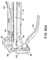
- Figures 2(a)-(c) are cutaway drawings of the preferred embodiment of a terminal connector tool in accordance with the invention.
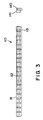
- Figure 3 is a drawing illustrating a preferred embodiment of a terminal connector strip in accordance with the invention.
- Figures 4(a)-(c) are exploded drawings further illustrating the operation of the preferred embodiment of the invention.
- terminating tool (100) includes a tool body (101) having crimping element (102), which is moveably attached to handle (103) to effectuate termination of wires, such as telephone cable wires, computer cable wires, and the like, to terminal connectors.
- Terminating tool (100) further includes end (104), into which a terminal connector strip is inserted, as described in more detail below.
- the terminating tool body (101) also includes a pusher track (105) for guiding pusher assembly (106).
- Pusher latch (107) is positioned at one end of pusher track (105) for securing pusher assembly (106) during the insertion of the terminal connector strip.
- the terminating tool also may include opening (108) in proximity to end (104), for attaching terminating tool (100) to a tool belt or the like.
- crimping element (102) may comprise, for example, a metal block, such as steel or any suitable material for providing pressure on the terminal connector.
- Crimping element (102) is attached to handle (103) using cam arm (129) in the manner shown. In this configuration, when handle (103) is moved toward tool body (101), cam arm (129) is thrust upward, forcing crimping element (102) against the terminal connector, which is in turn forced against flange (125) to complete the termination.
- Handle (103) also typically includes a counter spring (not shown) to provide a force for returning handle (103) to its extended position.
- Pusher assembly (106) pushes the terminal connectors forward along keyed track (121) using a number of means.
- pusher assembly may be attached to coil spring mechanism (131), which is mounted within the front portion of tool body (101), as shown, to provide a tensioning force to draw the assembly forward.
- the terminating tool (100) also preferably includes scales (109) for both two-wire and three-wire connectors. These scales help the user to identify the last few connectors remaining in the terminator connector strip within terminating tool (100). When using this scale, the user should relate the trailing edge of pusher assembly (106) with the proper scale to correctly determine how many connectors are remaining. For example, the user may reference a two-wire scale when using two-wire connectors, and a three-wire scale when using three-wire connectors. Other embodiments may provide termination for other wire connectors, e.g. single wire, four wire, etc.
- terminator connector strip (110) preferably comprises a series of individual terminal connectors (111) that are connected together to form a single strip or stick. Different means may be used to fasten the terminal connectors (111) together, such as the use of adhesive tape (113), which is affixed to the outside edge of the terminal connectors, as shown. However the connectors are preferably ultrasonically welded to each other at edges (112).
- Each terminator connector (111) typically comprises a base portion (140) and a cover portion (141). When the wires to be terminated are loaded into connector (111), cover portion (141) is pressed into base (140) in a conventional manner, securing the wires in place.
- Terminating tool preferably includes a keyed track (121) within cavity (120) for orienting and guiding terminal connector strip (110) therethrough.
- the user Before unlatching pusher assembly (106), the user should preferably verify that the connectors of terminal strip (110) are forward of arrow (122) in site window (123), which is preferably integral with gauge slots (124), as shown in Figure 4(b).
- site window (123) which is preferably integral with gauge slots (124), as shown in Figure 4(b).
- pusher assembly (106) Figure 4(a)
- This will advance all of the parts forward, and will locate the first connector in terminal connector strip (110) within crimping element (102) ( Figure 1).
- the user then inserts wires (127) to be terminated into the connector, closing the handle (103) until the connector cover is forced against the top of connector-housing flange (125) by crimping element (102), terminating the wires within the connector.
- handle (103) is released, the terminated connector is ejected from terminating tool (100), and a new connector is forced into position for termination by pusher assembly (106).
- the user may next verify that the termination is acceptable by placing the terminating connector in a gauge slot (124), preferably located on the handle side of the terminating tool, as shown in Figure 4(b).
- the user would determine the largest wire size terminated and select the gauge slot marked with the appropriate AWG (i.e., American Wire Gauge) size.
- the terminated connector is then preferably inserted into the largest opening for that gauge and slid into the appropriate slot with the end resting on locating shelf (126). If excessive drag is apparent, it will be necessary to close the tool handle tighter in future terminations.
- Failed connector assemblies may be repaired with a conventional loose piece-terminating tool, as well.
- the terminating tool of the present invention is capable of separating and terminating ultrasonically welded connector strips of various lengths, which provides significant benefits over the systems of the prior art.
- the terminating tool of the present invention allows for control of the terminating connector strip over the majority (e.g., ninety percent) of the pusher assembly track, with a minority (e.g., the last ten percent) of the track accurately locating the connector for termination.
- This control has a significant advantage in that it allows the ultrasonically welded strip to be manufactured more economically by using a more open assembly process.
- support rail (128) (Figure 2(b)) is beneficially provided within the last portion of the track to hold the cover (141) ( Figure 3) of the trailing connector open during termination.
- support rail (128) may comprise, for example, a raised guide portion (132) for accurately locating the connector for termination and a ribbed portion (133) for holding the cover open of the terminator connector behind the connector currently being terminated.
- the preferred embodiments of the present invention have a significant advantage in allowing the pusher assembly to be placed out of the way of the track and restrained when loading the terminal connector strip. Moreover, both the track and the latch position are contained within the profile of the tool, providing a more compact and efficient design.
- the outer part of the shell of the tool also preferably has raised feature (130) on both sides along the length of the tool, with a relieved channel (134) therein, allowing the pusher assembly to travel under the operator's hand while maintaining a grip on the tool.
- terminating tool body (101) is preferably ergonomically designed in this manner, which allows for the terminator connector strip to be easily loaded and fed through to crimping element (102) for termination.
- Tool body (101) is preferably molded using thermoplastics, but is not limited thereto.
- the preferred embodiments of the present invention also preferably have a keyed track, which allows the user to properly orient a connector strip, preventing a connector strip from being loaded incorrectly.
- the preferred embodiments also have a site window that allows the operator to verify that the product strip is loaded correctly as well.
- the preferred embodiments of the present invention preferably have the aforementioned gauge (124) molded into the tool itself for a quick verification of a good termination - eliminating the need for a separate gauging tool.
Landscapes
- Engineering & Computer Science (AREA)
- Manufacturing & Machinery (AREA)
- Manufacturing Of Electrical Connectors (AREA)
- Coupling Device And Connection With Printed Circuit (AREA)
Abstract
A wire termination system for terminating wires in at least one of a plurality of terminal connectors removably affixed to each other in a terminal connector strip has a body having a connector positioning cavity therein for receiving the terminal connector strip; a pushing element (106) within the positioning cavity for advancing the terminal connector strip within the positioning cavity; a crimping element (102) for receiving at least one of the plurality of terminal connectors from the pushing element (106); a support (128) within the positioning cavity for positioning at least one of the plurality of terminal connectors within the crimping element (102); and a handle (103) moveably attached to the crimping element (102) and the body. The handle (103) and the crimping element (102) are configured to terminate the wires within at least one of the plurality of terminal connectors and to separate the terminal connector from the terminal connector strip.
Description
- The present invention is related to wiring splicing systems. More particularly, the present invention is related to a terminal connector strip and associated crimping tool for terminating wires.
- Communication cables, such as telephone and computer network cables, and the like, are typically interconnected by terminating the individual wires within each cable with a terminating connector for insertion into patch panel, jack or the like. The connector is terminated by inserting the wires to be spliced into the terminal connector and then applying pressure to the terminal, causing a portion of it to crimp against the wires, holding them in place and creating an electrical contact between the terminal wire and the metal contacts within the terminal connector. This is typically accomplished by using a crimping tool.
- Terminating systems have conventionally utilized individual terminal connectors, or connectors that are fastened together with adhesive tape, that are inserted into the terminating tool and are crimped into place. In addition, terminating systems have incorporated a cartridge tube containing multiple rows of loose terminal connectors that are fed into the crimping tool as each set of wires is terminated. A hand-actuated crimping tool feeds connectors into the crimping area from the aforementioned pre-packaged expendable cartridges. In some models, in operation, a pusher mechanism is drawn back against a counter spring so that the taped connectors or connector cartridge may be loaded into the tool body. In other systems of the prior art, a rear cover on the tool is opened and a retractable draw cord used to pull back a spring-mounted pusher assembly until it is locked in the rear position by a pusher latch. An end cap is removed from the front end of the cartridge, which is then inserted into the tool. The rear cover is closed and latched, releasing the pusher and positioning the first connector into the terminating area.
- The wires to be terminated are then placed onto wire guides, which ensure that the wires have been split by separators and are lying in the proper wire channels. The wires are then fully inserted into the connectors, and the handle is closed and then allowed to open. Pulling the handle closed forces a terminating pin to terminate a wire within the connector in the manner previously described. When the handle is released, the tool automatically ejects the terminated connector and positions a new connector for termination.
- However, these systems have significant disadvantages. For example, the use of individual connectors is a slow and tedious process, since the user must individually load the tube or cartridge with connectors for use within the crimping tool. These systems also require expensive packaging to accommodate a single-track tube or four track cartridges. Moreover, the four track cartridges are typically difficult to load. The pusher latching mechanism described above is often unreliable, and the drawstring extends out of the rear of the tool. The tool body is square and not ergonomic; it is uncomfortable for the user. And, the selector knob on the front of tool often gets in the way when terminating wires in an enclosure.
- Accordingly, a system is needed that improves upon these disadvantages in the prior art.
- The present invention is directed to a wire termination system for terminating wires in at least one of a plurality of terminal connectors removably affixed to each other in a terminal connector strip that includes a body having a connector positioning cavity therein for receiving the terminal connector strip; a pushing element within the positioning cavity for advancing the terminal connector strip within the positioning cavity; a crimping element for receiving at least one of the plurality of terminal connectors from the pushing element; a support within the positioning cavity for positioning at least one of the plurality of connectors within the crimping element; and a handle moveably attached to the crimping element and the body, wherein the handle and the crimping element are configured to terminate the wires within at least one of the plurality of terminal connectors and to separate the terminal connector from the terminal connector strip.
- The wire terminator body also preferably includes a track along which the pushing element travels, wherein the track has a latch positioned to restrain the pushing element to allow the terminal connector strip to be inserted into the cavity. The tool body also preferably includes a slot window for viewing the terminal connector strip, a guide rail within the connector positioning cavity for guiding the terminal connector prior to termination and preventing the cover of the trailing connector from closing during termination, a key in the track to prevent the terminal connector strip from being loaded incorrectly, and one or more gauges for verifying the terminal connection.
- Figure 1 is a drawing illustrating a preferred embodiment of a terminal connector tool in accordance with the invention.
- Figures 2(a)-(c) are cutaway drawings of the preferred embodiment of a terminal connector tool in accordance with the invention.
- Figure 3 is a drawing illustrating a preferred embodiment of a terminal connector strip in accordance with the invention.
- Figures 4(a)-(c) are exploded drawings further illustrating the operation of the preferred embodiment of the invention.
- The invention will be understood more fully from the detailed description given below and from the accompanying drawings of the preferred embodiments of the invention; which, however, should not be taken to limit the invention to a specific embodiment but are for explanation and understanding only.
- The figures illustrate a preferred embodiment of a terminating tool in accordance with aspects of the invention. As shown in Figure 1, terminating tool (100) includes a tool body (101) having crimping element (102), which is moveably attached to handle (103) to effectuate termination of wires, such as telephone cable wires, computer cable wires, and the like, to terminal connectors. Terminating tool (100) further includes end (104), into which a terminal connector strip is inserted, as described in more detail below. The terminating tool body (101) also includes a pusher track (105) for guiding pusher assembly (106). Pusher latch (107) is positioned at one end of pusher track (105) for securing pusher assembly (106) during the insertion of the terminal connector strip. The terminating tool also may include opening (108) in proximity to end (104), for attaching terminating tool (100) to a tool belt or the like.
- As shown in Figures 2(a)-(c), crimping element (102) may comprise, for example, a metal block, such as steel or any suitable material for providing pressure on the terminal connector. Crimping element (102) is attached to handle (103) using cam arm (129) in the manner shown. In this configuration, when handle (103) is moved toward tool body (101), cam arm (129) is thrust upward, forcing crimping element (102) against the terminal connector, which is in turn forced against flange (125) to complete the termination. Handle (103) also typically includes a counter spring (not shown) to provide a force for returning handle (103) to its extended position.
- Pusher assembly (106) pushes the terminal connectors forward along keyed track (121) using a number of means. For example, pusher assembly may be attached to coil spring mechanism (131), which is mounted within the front portion of tool body (101), as shown, to provide a tensioning force to draw the assembly forward.
- As shown in Figure 1, the terminating tool (100) also preferably includes scales (109) for both two-wire and three-wire connectors. These scales help the user to identify the last few connectors remaining in the terminator connector strip within terminating tool (100). When using this scale, the user should relate the trailing edge of pusher assembly (106) with the proper scale to correctly determine how many connectors are remaining. For example, the user may reference a two-wire scale when using two-wire connectors, and a three-wire scale when using three-wire connectors. Other embodiments may provide termination for other wire connectors, e.g. single wire, four wire, etc.
- A preferred embodiment of a terminator connector strip is shown in Figure 3. As shown in Figure 3, terminator connector strip (110) preferably comprises a series of individual terminal connectors (111) that are connected together to form a single strip or stick. Different means may be used to fasten the terminal connectors (111) together, such as the use of adhesive tape (113), which is affixed to the outside edge of the terminal connectors, as shown. However the connectors are preferably ultrasonically welded to each other at edges (112). Each terminator connector (111) typically comprises a base portion (140) and a cover portion (141). When the wires to be terminated are loaded into connector (111), cover portion (141) is pressed into base (140) in a conventional manner, securing the wires in place.
- The operation of the preferred embodiment will now be explained in further detail, particularly in connection with Figures 4(a)-(c). To load the terminal connectors into the terminating tool, the user would retract the pusher assembly (106) along pusher track (105), securing it with pusher latch (107). The user would then load terminal connector strip (110) into cavity (120) through open end (104) of terminating tool body (101), as shown in Figure 4(a). Terminating tool preferably includes a keyed track (121) within cavity (120) for orienting and guiding terminal connector strip (110) therethrough.
- Before unlatching pusher assembly (106), the user should preferably verify that the connectors of terminal strip (110) are forward of arrow (122) in site window (123), which is preferably integral with gauge slots (124), as shown in Figure 4(b). When the last terminal connector is visible in site window (123), pusher assembly (106) (Figure 4(a)) may be unlatched. This will advance all of the parts forward, and will locate the first connector in terminal connector strip (110) within crimping element (102) (Figure 1).
- As shown in Figure 4(c), the user then inserts wires (127) to be terminated into the connector, closing the handle (103) until the connector cover is forced against the top of connector-housing flange (125) by crimping element (102), terminating the wires within the connector. When handle (103) is released, the terminated connector is ejected from terminating tool (100), and a new connector is forced into position for termination by pusher assembly (106).
- The user may next verify that the termination is acceptable by placing the terminating connector in a gauge slot (124), preferably located on the handle side of the terminating tool, as shown in Figure 4(b). The user would determine the largest wire size terminated and select the gauge slot marked with the appropriate AWG (i.e., American Wire Gauge) size. The terminated connector is then preferably inserted into the largest opening for that gauge and slid into the appropriate slot with the end resting on locating shelf (126). If excessive drag is apparent, it will be necessary to close the tool handle tighter in future terminations. Failed connector assemblies may be repaired with a conventional loose piece-terminating tool, as well.
- Thus, the terminating tool of the present invention is capable of separating and terminating ultrasonically welded connector strips of various lengths, which provides significant benefits over the systems of the prior art. Moreover, the terminating tool of the present invention allows for control of the terminating connector strip over the majority (e.g., ninety percent) of the pusher assembly track, with a minority (e.g., the last ten percent) of the track accurately locating the connector for termination. This control has a significant advantage in that it allows the ultrasonically welded strip to be manufactured more economically by using a more open assembly process.
- For this purpose, support rail (128) (Figure 2(b)) is beneficially provided within the last portion of the track to hold the cover (141) (Figure 3) of the trailing connector open during termination. As shown in the Figure 2(b), support rail (128) may comprise, for example, a raised guide portion (132) for accurately locating the connector for termination and a ribbed portion (133) for holding the cover open of the terminator connector behind the connector currently being terminated.
- By providing a positive latching feature at one end of a pusher assembly track, the preferred embodiments of the present invention have a significant advantage in allowing the pusher assembly to be placed out of the way of the track and restrained when loading the terminal connector strip. Moreover, both the track and the latch position are contained within the profile of the tool, providing a more compact and efficient design.
- As shown in Figure 1, in the preferred embodiment, the outer part of the shell of the tool also preferably has raised feature (130) on both sides along the length of the tool, with a relieved channel (134) therein, allowing the pusher assembly to travel under the operator's hand while maintaining a grip on the tool. Thus terminating tool body (101) is preferably ergonomically designed in this manner, which allows for the terminator connector strip to be easily loaded and fed through to crimping element (102) for termination. Tool body (101) is preferably molded using thermoplastics, but is not limited thereto.
- The preferred embodiments of the present invention also preferably have a keyed track, which allows the user to properly orient a connector strip, preventing a connector strip from being loaded incorrectly. In addition, the preferred embodiments also have a site window that allows the operator to verify that the product strip is loaded correctly as well.
- Finally, the preferred embodiments of the present invention preferably have the aforementioned gauge (124) molded into the tool itself for a quick verification of a good termination - eliminating the need for a separate gauging tool.
- Although this invention has been described with reference to particular embodiments, it will be appreciated that many variations will be resorted to without departing from the spirit and scope of this invention as set forth in the appended claims. For example, the invention may be used with any particular type or gauge of wire, including but not limited to two and three wire telephone cable, computer and power cables, etc.
Claims (24)
- A wire terminating system for terminating wires in at least one of a plurality of terminal connectors (111) removably affixed to each other in a terminal connector strip (110) comprising:a body (101) having a connector positioning cavity (120) therein for receiving said terminal connector strip;a pushing element (106) within said positioning cavity for advancing said terminal connector strip (110) within said positioning cavity;a crimping element (102) for receiving at least one of said plurality of terminal connectors (111) from said pushing element; anda support (128) within said positioning cavity for positioning at least one of said plurality of terminal connectors within said crimping element;a handle (103) moveably attached to said crimping element (102) and said body (101), wherein said handle and said crimping element are configured to terminate said wires within at least one of said plurality of terminal connectors (111) and to separate said terminal connector (111) from said terminal connector strip (110).
- The system of Claim 1, wherein said terminal connector (111) comprises a base portion (140) and a cover (141) and wherein said support (128) comprises a support rail (128) including a ribbed portion (133) for holding open said cover of at least one of said terminal connectors which is located behind said terminal connector in said crimping element (102).
- The system of Claim 1 or 2, wherein said terminal connector (111) is a two-wire or three-wire connector.
- The system of Claim 1, 2 or 3, wherein said body (101) further comprises a track (105) along which said pushing element (106) travels, said track having a latch positioned to restrain said pushing element to allow said terminal connector strip (110) to be inserted into said connector positioning cavity (120).
- The system of any one of the preceding Claims, wherein said tool body (101) further includes a slot window (123) for viewing said terminal connector strip (110).
- The system of any one of the preceding Claims, wherein said tool body (101) further includes a guide track (121) within said connector positioning cavity (120) for guiding said terminal connector strip (110) along its length.
- The system of Claim 6, wherein said guide track (121) is keyed for orienting said terminal connector strip (110).
- The system of any one of the preceding Claims, wherein said tool body (101) further includes one or more gauges (124) for verifying said terminal connection.
- The system of any one of the preceding Claims, wherein said terminal connectors (111) are removably affixed in said terminal connector strip (110) by ultrasonic welding or adhesive tape.
- The system of any one of the preceding Claims, wherein said tool body (101) further comprises a raised feature along its length to allow said pusher assembly to move freely when said tool body (101) is being held.
- In a wire terminating system having a terminating tool body (101) with a connector positioning cavity (120) therein, a pushing element (106) within said positioning cavity for advancing terminal connectors (111) therein, a crimping element (102) for receiving said terminal connectors (111) from said pushing element, and a handle (103) moveably attached to said crimping element and said body for terminating wires within said terminal connectors, a terminal connector strip (110) comprising a plurality of said terminal connectors (111) removably affixed to each other at a connection point by ultrasonic welding and capable of being separated from said terminal connector strip (110) by said crimping element (102) when said wires are terminated within said terminal connector (111).
- The connector strip of Claim 11, wherein said terminal connector (111) comprises a base portion (140) and a cover (141) and wherein a support rail (128) includes a ribbed portion (133) for holding open said cover of at least one of said terminal connectors which is located behind said terminal connector in said crimping element (102).
- A method of terminating wires comprising:inserting a terminal connector strip (110) having a plurality of terminal connectors (111) removably affixed to each other into a connector positioning cavity (120) within a terminating tool body (101);advancing at least one of said plurality of terminal connectors (111) in said terminal connector strip (110) within said positioning cavity (120);receiving at least one of said terminal connectors (111) within a crimping element (102) from said cavity; andpositioning at least one of said plurality of terminal connectors (111) to be received within said crimping element (102) using a support (128) within said positioning cavity (102);terminating said wires within at least one of said plurality of terminal connector (111) using said crimping element (102) to create a terminated terminal connector; andseparating said terminated terminal connector from said terminal connector strip (110).
- The method of Claim 13, wherein said terminal connector (111) comprises a base portion (140) and a cover (141) and wherein a support rail (128) includes a ribbed portion (133) for holding open said cover (141) of at least one of said terminal connectors which is located behind said terminal connector in said crimping element (102).
- The method of Claim 13, wherein said terminal connector is a two-wire or three-wire connector.
- The method of Claim 13, wherein said body (101) further comprises a track (105) along which said pushing element (106) travels, said track having a latch positioned to restrain said pushing element (106) to allow said terminal connector strip (110) to be inserted into said connector positioning cavity (120).
- The method of Claim 13, wherein said tool body (101) further includes a slot window (123) for viewing said terminal connector strip (110).
- The method of Claim 13, wherein said tool body (101) further includes a guide track (121) within said connector positioning cavity (102) for guiding said terminal connector strip (110) along its length.
- The method of Claim 12, wherein said guide track (121) is keyed for orienting said terminal connector strip (110).
- The method of Claim 13, wherein said tool body (101) further includes one or more gauges (124) for verifying said terminal connection.
- The method of Claim 13, wherein said terminal connectors (111) are removably affixed in said terminal connector strip (110) by ultrasonic welding or adhesive tape.
- The method of Claim 13, wherein said tool body (101) further comprises a raised feature along its length to allow said pusher assembly to move freely when said tool body (101) is being held.
- A method for terminating a wire using a terminal connector strip (110) comprising removably affixing a plurality of terminal connectors (111) to each other at a connection point by ultrasonic welding to form said terminal connector strip for insertion into a terminating tool body (106) having a support (128) therein for positioning each of said terminal connectors (111) to be received within a crimping element (102) for termination and separation from said terminal connector strip.
- The method of Claim 23, wherein said terminal connector (111) comprises a base portion (140) and a cover (141) and wherein the support comprises a support rail (128) including a ribbed portion (133) for holding open said cover (141) of at least one of said terminal connectors (111) which is located behind said terminal connector in said crimping element (102).
Applications Claiming Priority (2)
| Application Number | Priority Date | Filing Date | Title |
|---|---|---|---|
| US260474 | 1981-05-04 | ||
| US10/260,474 US6805169B2 (en) | 2002-09-30 | 2002-09-30 | Method and apparatus for wire splicing |
Publications (1)
| Publication Number | Publication Date |
|---|---|
| EP1403982A1 true EP1403982A1 (en) | 2004-03-31 |
Family
ID=31977922
Family Applications (1)
| Application Number | Title | Priority Date | Filing Date |
|---|---|---|---|
| EP20030256145 Withdrawn EP1403982A1 (en) | 2002-09-30 | 2003-09-30 | Method and apparatus for wire splicing |
Country Status (5)
| Country | Link |
|---|---|
| US (1) | US6805169B2 (en) |
| EP (1) | EP1403982A1 (en) |
| AR (1) | AR041429A1 (en) |
| BR (1) | BR0304279A (en) |
| MX (1) | MXPA03008921A (en) |
Cited By (1)
| Publication number | Priority date | Publication date | Assignee | Title |
|---|---|---|---|---|
| US7444744B2 (en) | 2005-04-14 | 2008-11-04 | Panduit Corp. | Tool for connectors assembly |
Citations (5)
| Publication number | Priority date | Publication date | Assignee | Title |
|---|---|---|---|---|
| US3641656A (en) * | 1969-10-21 | 1972-02-15 | Hartco Co | Clip applying and clinching tools |
| EP0318065A1 (en) * | 1984-08-17 | 1989-05-31 | THOMAS & BETTS INTERNATIONAL INC. | Bandolier for two-part connectors |
| US4953384A (en) * | 1988-02-05 | 1990-09-04 | Legrand | Magazine-type wiring accessory crimping tool |
| DE4104736A1 (en) * | 1991-02-15 | 1992-08-27 | Weidmueller C A Gmbh Co | Crimpable tag element for crimping tool for wire end connection - has guide projection for sliding engagement with guide path and storable e.g. in handle of tool |
| US5347705A (en) * | 1992-03-24 | 1994-09-20 | Firma Weidmuller Interface GmbH & Co. | Pliers for dressing conductor ends |
Family Cites Families (5)
| Publication number | Priority date | Publication date | Assignee | Title |
|---|---|---|---|---|
| US3249992A (en) * | 1965-04-23 | 1966-05-10 | Amp Inc | Device for making electrical connections |
| US3393438A (en) * | 1965-06-22 | 1968-07-23 | Amp Inc | Crimping tool |
| US3707867A (en) * | 1970-03-12 | 1973-01-02 | Minnesota Mining & Mfg | Cartridge-type crimping tool |
| DE4008515A1 (en) * | 1990-03-16 | 1991-09-19 | Zoller & Froehlich | HAND PRESS |
| CA2298309A1 (en) * | 2000-02-04 | 2001-08-04 | Herbert E. Leistner | Clip crimping tool |
-
2002
- 2002-09-30 US US10/260,474 patent/US6805169B2/en not_active Expired - Fee Related
-
2003
- 2003-09-29 BR BR0304279-0A patent/BR0304279A/en not_active Application Discontinuation
- 2003-09-29 AR ARP030103545A patent/AR041429A1/en not_active Application Discontinuation
- 2003-09-30 MX MXPA03008921A patent/MXPA03008921A/en unknown
- 2003-09-30 EP EP20030256145 patent/EP1403982A1/en not_active Withdrawn
Patent Citations (5)
| Publication number | Priority date | Publication date | Assignee | Title |
|---|---|---|---|---|
| US3641656A (en) * | 1969-10-21 | 1972-02-15 | Hartco Co | Clip applying and clinching tools |
| EP0318065A1 (en) * | 1984-08-17 | 1989-05-31 | THOMAS & BETTS INTERNATIONAL INC. | Bandolier for two-part connectors |
| US4953384A (en) * | 1988-02-05 | 1990-09-04 | Legrand | Magazine-type wiring accessory crimping tool |
| DE4104736A1 (en) * | 1991-02-15 | 1992-08-27 | Weidmueller C A Gmbh Co | Crimpable tag element for crimping tool for wire end connection - has guide projection for sliding engagement with guide path and storable e.g. in handle of tool |
| US5347705A (en) * | 1992-03-24 | 1994-09-20 | Firma Weidmuller Interface GmbH & Co. | Pliers for dressing conductor ends |
Cited By (2)
| Publication number | Priority date | Publication date | Assignee | Title |
|---|---|---|---|---|
| US7444744B2 (en) | 2005-04-14 | 2008-11-04 | Panduit Corp. | Tool for connectors assembly |
| US8006372B2 (en) | 2005-04-14 | 2011-08-30 | Panduit Corp. | Tool for connector assembly |
Also Published As
| Publication number | Publication date |
|---|---|
| MXPA03008921A (en) | 2005-06-03 |
| AR041429A1 (en) | 2005-05-18 |
| US20040060338A1 (en) | 2004-04-01 |
| BR0304279A (en) | 2004-08-31 |
| US6805169B2 (en) | 2004-10-19 |
Similar Documents
| Publication | Publication Date | Title |
|---|---|---|
| US4055889A (en) | Connector harness assembly machine | |
| US6872090B2 (en) | Cable terminating apparatus and method | |
| EP2260548B1 (en) | Termination tool | |
| US20040244190A1 (en) | Cable terminating apparatus and method | |
| US9484722B2 (en) | Pulling head assembly workstation | |
| US11489319B2 (en) | Method for installing a pulling head assembly | |
| CN111225768B (en) | Conductor positioning clamp for cable processing | |
| US11088502B1 (en) | Wire termination assembly station and universal applicator for insulation displacement (IDT) strip terminals and connectors therefor | |
| US4040179A (en) | Apparatus for mating first and second portions of an electrical connector | |
| US4554733A (en) | Termination tooling for applying connectors to flat cable | |
| US4754636A (en) | Connector locating device for crimping tools | |
| US4411608A (en) | Automatic apparatus for transferring electrical cords with terminal blades and for the testing thereof | |
| US6805169B2 (en) | Method and apparatus for wire splicing | |
| IE54549B1 (en) | A method of, and apparatus for, terminating an electrical conductor to an electrical connector | |
| US3713214A (en) | Wire splice assembly station | |
| US4214805A (en) | Methods of joining conductors | |
| JP2682595B2 (en) | Manufacturing method and manufacturing apparatus for two-core wire with sleeve | |
| US3152390A (en) | Electrical connector applying tool | |
| US4169645A (en) | Means and methods of joining conductors | |
| US4868976A (en) | Splicer tool | |
| US4052778A (en) | Apparatus for the simultaneous termination in terminal sleeves of a plurality of wires with a multi-pin connector | |
| EP4443678A1 (en) | Electrical wire stripping solution for automated splicing or welding | |
| JP2769247B2 (en) | Manufacturing method of wire crimping harness | |
| JPS6174211A (en) | Automatic terminal compression inserter | |
| US4583289A (en) | System and apparatus for termination of flat cable |
Legal Events
| Date | Code | Title | Description |
|---|---|---|---|
| PUAI | Public reference made under article 153(3) epc to a published international application that has entered the european phase |
Free format text: ORIGINAL CODE: 0009012 |
|
| AK | Designated contracting states |
Kind code of ref document: A1 Designated state(s): AT BE BG CH CY CZ DE DK EE ES FI FR GB GR HU IE IT LI LU MC NL PT RO SE SI SK TR |
|
| AX | Request for extension of the european patent |
Extension state: AL LT LV MK |
|
| AKX | Designation fees paid | ||
| REG | Reference to a national code |
Ref country code: DE Ref legal event code: 8566 |
|
| STAA | Information on the status of an ep patent application or granted ep patent |
Free format text: STATUS: THE APPLICATION IS DEEMED TO BE WITHDRAWN |
|
| 18D | Application deemed to be withdrawn |
Effective date: 20041001 |