EP1403949A1 - Catalyst-coated ionomer membrane with protective film layer and membrane-electrode-assembly made thereof - Google Patents
Catalyst-coated ionomer membrane with protective film layer and membrane-electrode-assembly made thereof Download PDFInfo
- Publication number
- EP1403949A1 EP1403949A1 EP20020021990 EP02021990A EP1403949A1 EP 1403949 A1 EP1403949 A1 EP 1403949A1 EP 20020021990 EP20020021990 EP 20020021990 EP 02021990 A EP02021990 A EP 02021990A EP 1403949 A1 EP1403949 A1 EP 1403949A1
- Authority
- EP
- European Patent Office
- Prior art keywords
- membrane
- catalyst
- coated
- layer
- protective film
- Prior art date
- Legal status (The legal status is an assumption and is not a legal conclusion. Google has not performed a legal analysis and makes no representation as to the accuracy of the status listed.)
- Granted
Links
- 239000012528 membrane Substances 0.000 title claims abstract description 118
- 230000001681 protective effect Effects 0.000 title claims abstract description 66
- 239000003054 catalyst Substances 0.000 title claims abstract description 63
- 229920000554 ionomer Polymers 0.000 title claims abstract description 43
- 239000000446 fuel Substances 0.000 claims abstract description 35
- 239000000463 material Substances 0.000 claims abstract description 28
- 238000000034 method Methods 0.000 claims abstract description 15
- 230000008569 process Effects 0.000 claims abstract description 13
- 238000004519 manufacturing process Methods 0.000 claims abstract description 10
- 238000009792 diffusion process Methods 0.000 claims description 25
- 229920000642 polymer Polymers 0.000 claims description 9
- -1 polytetrafluoroethylene Polymers 0.000 claims description 7
- 239000002861 polymer material Substances 0.000 claims description 5
- 229920001343 polytetrafluoroethylene Polymers 0.000 claims description 5
- 239000004810 polytetrafluoroethylene Substances 0.000 claims description 5
- 239000004952 Polyamide Substances 0.000 claims description 4
- 229920006018 co-polyamide Polymers 0.000 claims description 4
- 229920001971 elastomer Polymers 0.000 claims description 4
- 239000000806 elastomer Substances 0.000 claims description 4
- 229920000620 organic polymer Polymers 0.000 claims description 4
- 229920002647 polyamide Polymers 0.000 claims description 4
- 239000011147 inorganic material Substances 0.000 claims description 3
- 239000011368 organic material Substances 0.000 claims description 3
- 229920001643 poly(ether ketone) Polymers 0.000 claims description 3
- 229920002480 polybenzimidazole Polymers 0.000 claims description 3
- 229920002635 polyurethane Polymers 0.000 claims description 3
- 239000004814 polyurethane Substances 0.000 claims description 3
- 239000002033 PVDF binder Substances 0.000 claims description 2
- 239000004642 Polyimide Substances 0.000 claims description 2
- XUIMIQQOPSSXEZ-UHFFFAOYSA-N Silicon Chemical compound [Si] XUIMIQQOPSSXEZ-UHFFFAOYSA-N 0.000 claims description 2
- 239000002131 composite material Substances 0.000 claims description 2
- 229910010272 inorganic material Inorganic materials 0.000 claims description 2
- 229920000728 polyester Polymers 0.000 claims description 2
- 229920001721 polyimide Polymers 0.000 claims description 2
- 229920001296 polysiloxane Polymers 0.000 claims description 2
- 229920003225 polyurethane elastomer Polymers 0.000 claims description 2
- 229920002981 polyvinylidene fluoride Polymers 0.000 claims description 2
- 229910052710 silicon Inorganic materials 0.000 claims description 2
- 239000010703 silicon Substances 0.000 claims description 2
- 229920002379 silicone rubber Polymers 0.000 claims description 2
- 239000000126 substance Substances 0.000 claims description 2
- 150000003460 sulfonic acids Chemical class 0.000 claims description 2
- 239000004698 Polyethylene Substances 0.000 claims 1
- 239000004743 Polypropylene Substances 0.000 claims 1
- 229920000573 polyethylene Polymers 0.000 claims 1
- 229920001155 polypropylene Polymers 0.000 claims 1
- 238000007789 sealing Methods 0.000 abstract description 22
- OKKJLVBELUTLKV-UHFFFAOYSA-N Methanol Chemical compound OC OKKJLVBELUTLKV-UHFFFAOYSA-N 0.000 abstract description 12
- 201000000760 cerebral cavernous malformation Diseases 0.000 abstract description 8
- 238000000429 assembly Methods 0.000 abstract description 5
- 239000010410 layer Substances 0.000 description 94
- 210000004027 cell Anatomy 0.000 description 35
- 239000007789 gas Substances 0.000 description 21
- UFHFLCQGNIYNRP-UHFFFAOYSA-N Hydrogen Chemical compound [H][H] UFHFLCQGNIYNRP-UHFFFAOYSA-N 0.000 description 10
- 239000001257 hydrogen Substances 0.000 description 10
- 229910052739 hydrogen Inorganic materials 0.000 description 10
- 230000002093 peripheral effect Effects 0.000 description 7
- OKTJSMMVPCPJKN-UHFFFAOYSA-N Carbon Chemical compound [C] OKTJSMMVPCPJKN-UHFFFAOYSA-N 0.000 description 6
- 238000005516 engineering process Methods 0.000 description 5
- 229920000049 Carbon (fiber) Polymers 0.000 description 4
- 230000001070 adhesive effect Effects 0.000 description 4
- QVGXLLKOCUKJST-UHFFFAOYSA-N atomic oxygen Chemical compound [O] QVGXLLKOCUKJST-UHFFFAOYSA-N 0.000 description 4
- 238000003475 lamination Methods 0.000 description 4
- VNWKTOKETHGBQD-UHFFFAOYSA-N methane Chemical compound C VNWKTOKETHGBQD-UHFFFAOYSA-N 0.000 description 4
- 239000001301 oxygen Substances 0.000 description 4
- 229910052760 oxygen Inorganic materials 0.000 description 4
- 239000005518 polymer electrolyte Substances 0.000 description 4
- 239000011241 protective layer Substances 0.000 description 4
- 239000000853 adhesive Substances 0.000 description 3
- 229910052799 carbon Inorganic materials 0.000 description 3
- 239000004917 carbon fiber Substances 0.000 description 3
- 238000006243 chemical reaction Methods 0.000 description 3
- 239000012943 hotmelt Substances 0.000 description 3
- 230000007774 longterm Effects 0.000 description 3
- 229910052751 metal Inorganic materials 0.000 description 3
- 239000002184 metal Substances 0.000 description 3
- 239000002245 particle Substances 0.000 description 3
- BASFCYQUMIYNBI-UHFFFAOYSA-N platinum Chemical group [Pt] BASFCYQUMIYNBI-UHFFFAOYSA-N 0.000 description 3
- 239000012812 sealant material Substances 0.000 description 3
- 239000004831 Hot glue Substances 0.000 description 2
- 239000006229 carbon black Substances 0.000 description 2
- 235000019241 carbon black Nutrition 0.000 description 2
- 229920000295 expanded polytetrafluoroethylene Polymers 0.000 description 2
- 229910002804 graphite Inorganic materials 0.000 description 2
- 239000010439 graphite Substances 0.000 description 2
- 230000002209 hydrophobic effect Effects 0.000 description 2
- 238000005470 impregnation Methods 0.000 description 2
- 238000007689 inspection Methods 0.000 description 2
- 238000005342 ion exchange Methods 0.000 description 2
- 239000007788 liquid Substances 0.000 description 2
- 239000007800 oxidant agent Substances 0.000 description 2
- 230000003647 oxidation Effects 0.000 description 2
- 238000007254 oxidation reaction Methods 0.000 description 2
- 230000009467 reduction Effects 0.000 description 2
- 230000003014 reinforcing effect Effects 0.000 description 2
- 239000007787 solid Substances 0.000 description 2
- 239000000758 substrate Substances 0.000 description 2
- 229920001169 thermoplastic Polymers 0.000 description 2
- 239000004416 thermosoftening plastic Substances 0.000 description 2
- XLYOFNOQVPJJNP-UHFFFAOYSA-N water Substances O XLYOFNOQVPJJNP-UHFFFAOYSA-N 0.000 description 2
- 210000003771 C cell Anatomy 0.000 description 1
- 229920000557 Nafion® Polymers 0.000 description 1
- 229910002849 PtRu Inorganic materials 0.000 description 1
- 239000004809 Teflon Substances 0.000 description 1
- 229920006362 Teflon® Polymers 0.000 description 1
- 239000011149 active material Substances 0.000 description 1
- 239000000654 additive Substances 0.000 description 1
- 239000012790 adhesive layer Substances 0.000 description 1
- 239000003570 air Substances 0.000 description 1
- 230000015572 biosynthetic process Effects 0.000 description 1
- 239000011248 coating agent Substances 0.000 description 1
- 238000000576 coating method Methods 0.000 description 1
- 239000002322 conducting polymer Substances 0.000 description 1
- 229920001940 conductive polymer Polymers 0.000 description 1
- 239000000356 contaminant Substances 0.000 description 1
- 238000010924 continuous production Methods 0.000 description 1
- 229920001577 copolymer Polymers 0.000 description 1
- 230000006866 deterioration Effects 0.000 description 1
- 238000001035 drying Methods 0.000 description 1
- 230000005611 electricity Effects 0.000 description 1
- 239000010411 electrocatalyst Substances 0.000 description 1
- 239000000839 emulsion Substances 0.000 description 1
- 239000004744 fabric Substances 0.000 description 1
- 239000012530 fluid Substances 0.000 description 1
- 239000002737 fuel gas Substances 0.000 description 1
- 150000002430 hydrocarbons Chemical group 0.000 description 1
- 230000006872 improvement Effects 0.000 description 1
- 238000009434 installation Methods 0.000 description 1
- 230000003993 interaction Effects 0.000 description 1
- 125000003010 ionic group Chemical group 0.000 description 1
- 238000010030 laminating Methods 0.000 description 1
- 150000002739 metals Chemical class 0.000 description 1
- 239000002105 nanoparticle Substances 0.000 description 1
- 230000000149 penetrating effect Effects 0.000 description 1
- 230000000737 periodic effect Effects 0.000 description 1
- 229910052697 platinum Inorganic materials 0.000 description 1
- 239000004848 polyfunctional curative Substances 0.000 description 1
- 239000011148 porous material Substances 0.000 description 1
- 230000002265 prevention Effects 0.000 description 1
- 238000007639 printing Methods 0.000 description 1
- 239000000376 reactant Substances 0.000 description 1
- 239000012429 reaction media Substances 0.000 description 1
- 230000006641 stabilisation Effects 0.000 description 1
- 238000011105 stabilization Methods 0.000 description 1
- 125000000542 sulfonic acid group Chemical group 0.000 description 1
Images
Classifications
-
- H—ELECTRICITY
- H01—ELECTRIC ELEMENTS
- H01M—PROCESSES OR MEANS, e.g. BATTERIES, FOR THE DIRECT CONVERSION OF CHEMICAL ENERGY INTO ELECTRICAL ENERGY
- H01M8/00—Fuel cells; Manufacture thereof
- H01M8/02—Details
- H01M8/0271—Sealing or supporting means around electrodes, matrices or membranes
- H01M8/0273—Sealing or supporting means around electrodes, matrices or membranes with sealing or supporting means in the form of a frame
-
- H—ELECTRICITY
- H01—ELECTRIC ELEMENTS
- H01M—PROCESSES OR MEANS, e.g. BATTERIES, FOR THE DIRECT CONVERSION OF CHEMICAL ENERGY INTO ELECTRICAL ENERGY
- H01M4/00—Electrodes
- H01M4/86—Inert electrodes with catalytic activity, e.g. for fuel cells
-
- H—ELECTRICITY
- H01—ELECTRIC ELEMENTS
- H01M—PROCESSES OR MEANS, e.g. BATTERIES, FOR THE DIRECT CONVERSION OF CHEMICAL ENERGY INTO ELECTRICAL ENERGY
- H01M8/00—Fuel cells; Manufacture thereof
- H01M8/24—Grouping of fuel cells, e.g. stacking of fuel cells
- H01M8/241—Grouping of fuel cells, e.g. stacking of fuel cells with solid or matrix-supported electrolytes
- H01M8/242—Grouping of fuel cells, e.g. stacking of fuel cells with solid or matrix-supported electrolytes comprising framed electrodes or intermediary frame-like gaskets
-
- H—ELECTRICITY
- H01—ELECTRIC ELEMENTS
- H01M—PROCESSES OR MEANS, e.g. BATTERIES, FOR THE DIRECT CONVERSION OF CHEMICAL ENERGY INTO ELECTRICAL ENERGY
- H01M8/00—Fuel cells; Manufacture thereof
- H01M8/10—Fuel cells with solid electrolytes
- H01M2008/1095—Fuel cells with polymeric electrolytes
-
- H—ELECTRICITY
- H01—ELECTRIC ELEMENTS
- H01M—PROCESSES OR MEANS, e.g. BATTERIES, FOR THE DIRECT CONVERSION OF CHEMICAL ENERGY INTO ELECTRICAL ENERGY
- H01M2300/00—Electrolytes
- H01M2300/0017—Non-aqueous electrolytes
- H01M2300/0065—Solid electrolytes
- H01M2300/0082—Organic polymers
-
- H—ELECTRICITY
- H01—ELECTRIC ELEMENTS
- H01M—PROCESSES OR MEANS, e.g. BATTERIES, FOR THE DIRECT CONVERSION OF CHEMICAL ENERGY INTO ELECTRICAL ENERGY
- H01M8/00—Fuel cells; Manufacture thereof
- H01M8/10—Fuel cells with solid electrolytes
- H01M8/1004—Fuel cells with solid electrolytes characterised by membrane-electrode assemblies [MEA]
-
- Y—GENERAL TAGGING OF NEW TECHNOLOGICAL DEVELOPMENTS; GENERAL TAGGING OF CROSS-SECTIONAL TECHNOLOGIES SPANNING OVER SEVERAL SECTIONS OF THE IPC; TECHNICAL SUBJECTS COVERED BY FORMER USPC CROSS-REFERENCE ART COLLECTIONS [XRACs] AND DIGESTS
- Y02—TECHNOLOGIES OR APPLICATIONS FOR MITIGATION OR ADAPTATION AGAINST CLIMATE CHANGE
- Y02E—REDUCTION OF GREENHOUSE GAS [GHG] EMISSIONS, RELATED TO ENERGY GENERATION, TRANSMISSION OR DISTRIBUTION
- Y02E60/00—Enabling technologies; Technologies with a potential or indirect contribution to GHG emissions mitigation
- Y02E60/30—Hydrogen technology
- Y02E60/50—Fuel cells
-
- Y—GENERAL TAGGING OF NEW TECHNOLOGICAL DEVELOPMENTS; GENERAL TAGGING OF CROSS-SECTIONAL TECHNOLOGIES SPANNING OVER SEVERAL SECTIONS OF THE IPC; TECHNICAL SUBJECTS COVERED BY FORMER USPC CROSS-REFERENCE ART COLLECTIONS [XRACs] AND DIGESTS
- Y02—TECHNOLOGIES OR APPLICATIONS FOR MITIGATION OR ADAPTATION AGAINST CLIMATE CHANGE
- Y02P—CLIMATE CHANGE MITIGATION TECHNOLOGIES IN THE PRODUCTION OR PROCESSING OF GOODS
- Y02P70/00—Climate change mitigation technologies in the production process for final industrial or consumer products
- Y02P70/50—Manufacturing or production processes characterised by the final manufactured product
Definitions
- the present invention is directed to catalyst-coated membranes and membrane-electrode-assemblies that contain ionomer membranes that have both an active area, which has a catalyst layer, and a passive area. Both of these areas are at least in part coated with a protective film.
- the active area may be coated with a gas diffusion layer.
- the protective film in a first step as a liquid, to press the GDL into the liquid film and to cure the film providing a solid protective film penetrating the GDL.
Landscapes
- Chemical & Material Sciences (AREA)
- General Chemical & Material Sciences (AREA)
- Electrochemistry (AREA)
- Chemical Kinetics & Catalysis (AREA)
- Sustainable Development (AREA)
- Sustainable Energy (AREA)
- Life Sciences & Earth Sciences (AREA)
- Manufacturing & Machinery (AREA)
- Engineering & Computer Science (AREA)
- Fuel Cell (AREA)
- Inert Electrodes (AREA)
- Separation Using Semi-Permeable Membranes (AREA)
- Catalysts (AREA)
- Measurement And Recording Of Electrical Phenomena And Electrical Characteristics Of The Living Body (AREA)
- Immobilizing And Processing Of Enzymes And Microorganisms (AREA)
Abstract
Description
- The present invention relates to the field of electrochemical cells and fuel cells.
- Fuel cells convert a fuel and an oxidizing agent into electricity, heat and water at two spatially separated electrodes. Typically in fuel cells, hydrogen or a hydrogen-rich gas is used as the fuel, and oxygen or air is used as the oxidizing agent.
- The energy conversion process in fuel cells is distinguished by particularly high efficiency. For this reason, fuel cells are gaining increasing importance for mobile, stationary and portable applications.
- The polymer electrolyte membrane fuel cell (PEMFC) and the direct methanol fuel cell (DMFC, a variation of the PEMFC, powered directly by methanol instead of hydrogen) are two common types of fuel cells that are used as energy converting devices. They are attractive choices because typically, they have compact designs, desirable power densities and high efficiencies.
- The technology of fuel cells is well known to persons skilled in the art and is broadly described in the literature, see for example, K. Kordesch and G. Simader, "Fuel Cells and its Applications," VCH Verlag Chemie, Weinheim (Germany) 1996. Nonetheless, in order to aid in the understanding of the present invention, in the following section, certain technical terms and phrases that are used in the present disclosure are described in greater detail:
- A "catalyst-coated membrane" (hereinafter abbreviated "CCM") consists of a polymer electrolyte membrane that is provided on both sides with a catalytically active layer. One of the layers takes the form of an anode for the oxidation of hydrogen and the other layer takes the form of a cathode for the reduction of oxygen. Because the CCM consists of three layers (anode catalyst layer, ionomer membrane and cathode catalyst layer), it is often referred to as a "three-layer MEA." As outlined in this disclosure, a CCM may also contain one or more film layers for better protection, handling and sealing of the product.
- "Gas diffusion layers" ("GDLs"), sometimes referred to as gas diffusion substrates or backings, are placed onto the anode and cathode layers of the CCM in order to bring the gaseous reaction media (e.g., hydrogen and air) to the catalytically active layers and, at the same time, to establish an electrical contact. GDLs usually consist of carbon-based substrates, such as carbon fiber paper or woven carbon fabric, which are highly porous and provide the reaction gases with good access to the electrodes. Furthermore, they are hydrophobic and permit removal of the product water from the fuel cell. Additionally, GDLs can be coated with a microlayer in order to improve the contact to the membrane. They can also be tailored specifically into anode-type GDLs or cathode-type GDLs, depending on into which side they are built in a given MEA. Furthermore, they can be coated with a catalyst layer and subsequently laminated to the ionomer membrane. These types of catalyst-coated GDLs are frequently referred to as "catalyst-coated backings" (abbreviated "CCBs") or gas diffusion electrodes ("GDEs").
- A "membrane-electrode-assembly" ("five-layer MEA") is the central component in a polymer-electrolyte-membrane (PEM) fuel cell and consists of five layers: the anode GDL; the anode catalyst layer; the ionomer membrane; the cathode catalyst layer; and the cathode GDL. A MEA can be manufactured by combining a CCM with two GDLs (on the anode and the cathode side) or, alternatively, by combining an ionomer membrane with two catalyst-coated backings (CCBs) at the anode and the cathode sides. In both cases, a five-layer MEA product is obtained. When the CCM contains one or more protective film layers integrated in the laminated assembly, the five-layer MEA in turn contains the protective film layer or layers as well.
- The anode and cathode catalyst layers are comprised of electrocatalysts that catalyze the respective reactions (e.g., oxidation of hydrogen at the anode and reduction of oxygen at the cathode). Preferably, the metals of the platinum group of the periodic table are used as the catalytically active components, and for the most part, supported catalysts are used in which the catalytically active platinum group metals have been fixed in nano-sized particle form to the surface of a conductive support material. By way of example, carbon blacks with particle sizes of 10 to 100 nm and high electrical conductivity have proven to be suitable as support materials. In these applications, the average particle size of the platinum group metal is typically between about 1 and 10 nm.
- The "polymer electrolyte membrane" consists of proton-conducting polymer materials. These materials are also referred to below as ionomer membranes. In ionomer membranes, tetrafluoroethylene-fluorovinyl-ether copolymer with sulfonic acid groups is preferably used. This material is marketed, for example, by E.I. DuPont under the trade name Nafion®. However, other, especially fluorine-free, ionomer materials such as sulfonated polyether ketones or aryl ketones or acid-doped polybenzimidazoles may also be used. Examples of materials that are suitable as ionomer materials are described by O. Savadogo in "Journal of New Materials for Electrochemical Systems" I, 47-66 (1998). For application in fuel cells, these membranes generally have a thickness between 10 and 200 µm.
- Within fuels cells several membrane-electrode-assemblies and bipolar plates are stacked in series to obtain the desired voltage output. As persons skilled in the art are aware, in fuel cell stack technology, sealing of components is an important issue. Generally, it is necessary to achieve a gas-tight sealing of these components (predominantly CCMs, MEAs and bipolar plates) against leakage to the environment and against intermixing of the reactants (hydrogen and oxygen/air). This gas-tight seal is essential for the safety of a PEMFC stack. (Lack of safety is a serious obstacle for the widespread introduction of fuel cell technology.) Thus, the quality and endurance of the seals and the materials used for them are of primary importance.
- For different stack architectures and operating conditions (such as pressure, temperature, fuel gases and lifetime required) different sealing concepts and technologies must be applied and developed. Furthermore, an appropriate sealing concept for CCMs and MEAs should also take into account an improvement for better protection and better handling of these products. Better handling and processing is particularly important in view of a large scale continuous production of CCMs and MEAs.
- Various concepts and technologies for sealing of MEAs and CCMs are described in the prior art.
- In U.S. Patent No. 3,134,697, a sealing function is conventionally achieved by using pre-cut frames of a polymer material and placing these frames around the electrodes of the fuel cell between the membrane and the bipolar plates of the cell. However, this concept suffers from the high efforts needed for exact handling and positioning of the cell, membrane-electrode-assembly and gasket frames. Thus, there is no close contact between membrane and sealing.
- EP 690 519 addresses the stabilization of the membrane in the inactive sealing region. It relates to an assembly consisting of at least one seal layer in a solid polymer ion exchange layer, wherein the seal layer or layers cover essentially only the region of the ion exchange layer that is to be sealed. According to this application, the sealing layer is made of polytetrafluoroethylene (PTFE) film having one surface coated and partially impregnated with the ionomer material.
- A similar concept is pursued in WO 00/74160. This document describes a membrane electrode unit for fuel cells. There the membrane electrode unit comprises a reinforcing frame that is situated on the periphery and in the area of openings that are placed in the active portion of the membrane electrode unit and provided for guiding material or for installation. A reinforcing frame is formed by a hot melt type adhesive layer that is applied on both sides and is formed by at least one rigid plate.
- All of these concepts described in the aforementioned references are based on sealing frames or layers that cover the peripheral membrane rim of the CCM/MEA and only stabilize this peripheral rim. However, depending on fuel cell operating parameters, frequently failures in the membrane material may occur at the interface between the active area and the sealing layers. Therefore, sufficient overlap is needed between the sealing/gasket layer, the active electrode layer and the ionomer membrane.
- WO 00/74161 relates to a membrane-electrode-assembly provided for fuel cells or the like that comprises an ionomer membrane that is coated on both sides with electrodes. The sealing edge, which is configured on the outer periphery, is comprised of a hot melt adhesive whose hydrocarbon skeleton carries, at regular intervals, ionic or strong polar groups that enter into a surface interaction with the ionic groups of the membrane material and thus provides for good adhesive effect of the hot melt type adhesive to the polymer electrolyte membrane. The thermoplastic sealing made of hot melt type adhesive extends on both sides over the edge section of the membrane. Unfortunately, associated with this method are high production costs, as well as costs for the application form of the hot-melt adhesive. Furthermore, its long-term stability is not proven; various components (such as hardeners, defoamers and other additives) may be leached out during operation and may cause deterioration of the MEA.
- WO 00/10216 describes a membrane electrode gasket assembly ("MEGA") having a gasket and a sub-gasket to seal the MEA and to protect it from possible edge failures. The gasket material typically consists of expanded polytetrafluoroethylene (e-PTFE), soaked with a solution of ionomer for better adhesion. The sub-gasket is disposed over a peripheral portion of an electrode, which is applied to a central portion of an ionomer membrane. In the examples given in WO 00/10216, a simultaneous overlapping of the sub-gasket with the electrode portion and the non-coated ionomer membrane portion is not disclosed.
- A different concept is suggested in U.S. Patent No. 5,176,966. According to that patent, seals are formed by impregnating the layers of porous electroconductive sheet material of the membrane-electrode-assembly with a sealant material that generally circumscribes the fluid passage openings and the electrochemical active portions of the assembly.
- Another disclosure, WO 98/33225, is directed to a sealing that penetrates an edge of at least one gas diffusion electrode (GDE) whereby the pores of the electrodes are filled. In that disclosure, the sealing is bonded to the membrane where the sealing penetrates the electrodes and comes into contact with the membrane and is also bonded to the peripheral face of the membrane. Both surfaces of the membrane are essentially completely covered by the electrodes.
- The latter two concepts, which are based on impregnation of gas diffusion electrodes (GDEs) with a sealant material, suffer from the complexity of the impregnation process. Even small deviations of the process parameters strongly affect quality of sealing and the smoothness of the contact surface of the sealed area. Consequently, it is very difficult to obtain gas-tight seals.
- In light of the shortcomings of the prior art, the present invention is directed to an improved catalyst-coated membrane that avoids the described disadvantages of the state of the art. In particular, the present invention provides a catalyst-coated membrane embracing one or more protective film layers that offers the following advantages: (i) improved mechanical stability; (ii) improved protection against membrane damage; and (iii) improved handling properties in cell/stack assembly. The present invention also provides an improved membrane-electrode-assembly (MEA) that offers the above-mentioned advantages. Finally, a process for manufacture of these improved products is outlined.
- The present invention relates to the field of electrochemical cells and fuel cells, more specifically to polymer-electrolyte-membrane fuel cells (PEMFC) and direct methanol fuel cells (DMFC), and describes catalyst-coated ionomer membranes ("CCMs") embracing one or more film layers for protection, sealing and handling purposes. The catalyst-coated membranes may, for example, be used as components for membrane-electrode-assemblies (MEAs) in low temperature fuel cell stacks.
- According to one embodiment, the present invention provides a catalyst-coated membrane that comprises:
- a) an ionomer membrane, wherein said ionomer membrane comprises two surfaces and each of said two surfaces is comprised of:
- (i) an active area, wherein said active area is coated with a catalyst layer; and
- (ii) a passive area; and
- b) at least one layer of protective film attached to each of the two surfaces of said catalyst coated membrane, wherein said at least one layer of protective film overlaps the active area and the passive area.
- According to a second embodiment, the present invention provides a membrane-electrode-assembly comprising:
- (a) an ionomer membrane, wherein said ionomer membrane comprises two surfaces and each of said two surfaces is comprised of:
- (i) an active area, wherein said active area is coated with a catalyst layer, and
- (ii) a passive area; and
- b) at least one gas diffusion layer, wherein said at least one gas diffusion layer covers the active area of said catalyst-coated membrane; and
- c) at least one layer of protective film, wherein said at least one layer of protective film contacts the active area, the passive area and the gas diffusion layer to form:
- (i) an overlapped region of the active area,
- (ii) an overlapped region of the passive area, and
- (iii) an overlapped region of the gas diffusion layer.
- In both of these embodiments, the passive area is the area of the ionomer membrane that has not been coated with a catalyst layer, and preferably, it forms a perimeter around the active area.
- These CCM and MEA are preferably manufactured under pressure and heat for a period of 0.1 to 15 minutes. More preferably, the pressure is in the range of 10 to 100 bar and the temperature is in the range of 20 to 200°C.
-
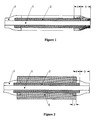
- Figure 1 is a representation of a catalyst-coated membrane (CCM) according to a first embodiment of the present invention.
- Figure 2 is a representation of a cross-section of a membrane-electrode-assembly (MEA) with protective film layers according to a second embodiment of the present invention.
- The present invention is directed to catalyst-coated membranes and membrane-electrode-assemblies that contain ionomer membranes that have both an active area, which has a catalyst layer, and a passive area. Both of these areas are at least in part coated with a protective film. In the MEA, the active area may be coated with a gas diffusion layer.
- The present disclosure is not intended to be a treatise on catalyst-coated membranes or membrane-electrode-assemblies. Readers are referred to appropriate available texts for background on these subjects.
- According to the present invention, the catalyst coated membrane preferably comprises an ionomer membrane that itself is comprised of a substance selected from the group consisting of perfluorinated sulfonic acid polymers, acid-doped polybenzimidazoles, acid-group-modified polyetherketones, ionically conductive organic/inorganic materials and composite reinforced materials.
- Catalyst coated membranes typically have two sides that contain catalytically active materials. Each of these sides is referred to herein as a "surface." On each of the two surfaces of the ionomer membrane, there is both an active area and a passive area. The active area, which corresponds to the electrode area is coated with a catalyst layer. The passive area, which is not coated, preferably forms a peripheral rim around the active area.
- A protective film layer covers at least a portion of both the active area and the passive area. The protective film layer embraces the CCM on both sides of the membrane, and has two main features. First, it overlaps the active area in a certain region sufficient for prevention of membrane damage. Second, it overlaps a significant region of the passive, non-coated area of the CCM. The region of the active area overlapped by the protective film layer is preferably in the range of 0.5 to 20 % of the total active area, and more preferably in the range of from 3 to 10 %. On the other hand, the region of the passive membrane area overlapped by the protective film layer is preferably in the range of 80 to 150 %, more preferably in the range of 80 to 100% and most preferred equal to 100 %, of the total non-coated membrane area. Overlapping of more than 100 % in the context of the present invention means that the protective film would extend over the periphery of the ionomer membrane.
- Preferably, the film comprises an organic polymer material with a thickness in the range of 10 to 150 µm. More preferably, the organic polymer material is a thermoplastic, duroplastic or elastomeric polymer comprised of a polymer selected from the group consisting of polytetrafluoroethylene, PVDF, polyester, polyamide, co-polyamide, polyamide elastomers, polyimide, polyurethane, polyurethane elastomers, silicones, silicon rubbers and silicon based elastomers.
- Generally, one or more film layers can be applied on the front and/or on the back surface of the catalyst-coated membrane. During lamination, the protective film softens and can penetrate the electrode layer.
- In a preferred embodiment, the protective film layers are applied as frames on both sides of the ionomer membrane. However, other patterns and dimensions are possible.
- The protective film layer or layers may be punched or perforated as needed for certain bipolar plate and PEM stack architectures. Additional layers of protective films, such as gaskets or sealant materials may be added afterwards.
- The present invention has two major embodiments, which are demonstrated in figures 1 and 2, and that may be incorporated into and operated in fuel cells such as PEMFCs and DMFCs.
- Figure 1 shows a schematic drawing (cross section) of a catalyst-coated membrane (CCM) according to the first embodiment of the present invention. According to this embodiment, the ionomer membrane (1) is coated on both sides with an electrode layer (2) forming the active area of the catalyst-coated membrane. Two frames of protective film layer (3) are applied on both sides to the passive area of the membrane (1) in such a way that the film layers overlap with the electrode layers in an area region (4), and, simultaneously, with the passive, non-coated area of the ionomer membrane in an area region (5). On each side of the membrane, the region covered or overlapped by the protective film layer is in the range of 0.5 to 20 % of the total active area of the membrane.
- The protective film may be made of a polymer that is more rigid than the ionomer membrane. The thickness of the protective film is preferably in the range of 10 µm to 150 µm (more preferably in the range of 80 to 120 µm), which enables it to constitute a protection for the ionomer membrane against pressure, impact, wear, heat, drying out, etc. In certain cases the thickness of the protective film may exceed 150 µm - especially when the protective film has also to function as a compressible sealing.
- The protective film layer is tightly fixed onto the membrane. It can be pre-shaped and heat-laminated or attached by an adhesive onto the membrane. It can also be formed by coating (by paste application, printing process, etc.) the non-coated membrane area with an appropriate polymer paste or polymer emulsion.
- The respective materials should be stable and resistant to the operating conditions of a PEM fuel cell. Furthermore, the materials should have high endurance and lifetime, as well as high purity in respect to trace contaminants, residual volatile components and other inorganic or organic materials that could be leached out during operation of the fuel cell.
- Figure 2 depicts a cross-section of a membrane-electrode-assembly (MEA) with protective film layers according to the second embodiment of the present invention. In this second embodiment, the active area of the CCM according to embodiment 1 is covered by gas diffusion layers (GDLs) in such a way, that the gas diffusion layers contact, overlap and/or penetrate the protective film layer applied to the CCM. Again, the ionomer membrane (1) is coated with an electrode layer (2) on both sides. The area of the active layer (2) (the "active area") is smaller than the total area of the ionomer membrane, which results in a peripheral rim of uncoated ionomer material (which is the passive non-coated area) around the central active area of the CCM. As already described in embodiment 1, two frames of protective film layers (3) are attached on both sides to the passive area of the membrane (1) in such a way that the film layers overlap with the electrode layers in an area region (4), and, simultaneously, with the passive, non-coated area of the ionomer membrane in an area region (5). On each side of the CCM, the region covered/overlapped by the protective film layer is in the range of 0.5 to 20 % of the total active area. Both surfaces of the CCM are additionally covered by gas diffusion layers (6). These two gas diffusion layers (GDLs) overlap/contact the protective film layer disposed over part of the active area at both sides of the membrane (overlapping region 7).
- In a preferred embodiment, the dimensions of the GDL and that of the active area are identical. In this case, the region of the active area of the CCM overlapped by the protective film and the region of the GDL in contact with the protective film are identical. However, other embodiments, involving GDLs with bigger or smaller dimensions compared to the active CCM area, are possible. Thus, the region of the GDL contacted by the layer of protective film can be in the range of 0.5 to 50 % of the total area of the gas diffusion layer.
- It is furthermore feasible, to provide the protective film in a first step as a liquid, to press the GDL into the liquid film and to cure the film providing a solid protective film penetrating the GDL.
- Commercially available GDLs, as well as other suitable materials can be used for the formation of the membrane-electrode-assembly (MEA) according to this invention. As base materials for GDLs, woven carbon cloth, non-woven carbon fiber layers or carbon fiber papers can be used. Typical GDL base materials include Toray TGP-H-060 and Textron AvCarb 1071 HCB supplied by Textron Inc. The gas diffusion layers may or may not be treated to be hydrophobic. Additionally, they may comprise additional carbon black microlayers and catalyst layers, if necessary.
- Bonding of the GDLs to the CCM can be conducted by application of pressure and heat. Appropriate bonding or laminating conditions have to be adopted to the mechanical stability of the individual base material of the GDLs.
- The following examples describe the scope of the invention in more detail. These examples are presented to aid in an understanding of the present invention and are not intended, and should not be construed, to limit the invention in any way.
- The catalyst-coated membrane used in this example was manufactured according to U.S. Patent No. 6,309,772, example 3, ink A. A 40 wt.% Pt/Vulcan XC72 catalyst was used as cathode catalyst, and a 40 wt.% PtRu (1:1)/Vulcan XC72 was employed for the anode side. The CCM product is available at OMG under the designation "CCM-Type 7C" and was used with a 100 cm2 (10 x 10 cm) of active area. The passive area (the non-coated area) of the CCM had a size of 1.0 cm in width, resulting in overall CCM dimensions of 12 x 12 cm with the active area centered in the middle.
- Co-polyamide Vestamelt 3261 (Degussa, Düsseldorf) was provided as an extruded film of 120 µm thickness. From this film, two square-sized frames were punched with inner dimensions of 9.8 x 9.8 cm and outer dimensions of 12 x 12 cm.
- The catalyst-coated membrane was placed between the two frames of protective film, and the assembly was covered by two sheets of PTFE blanks. The protective film frames were positioned with respect to the catalyst-coated membrane so that the peripheral membrane rim was completely covered, and a 2 mm broad region of the active area was overlapping with the inner edge of the frame of protective film on both sides of the CCM. Thus, the area of the overlapping region was 4 % of the total active area on both sides of the CCM. The region of the protective film overlapping with the non-coated membrane area was 100 % of the total non-coated membrane area on both sides of the CCM.
- The package was placed between two graphite press plates and transferred into a press with a temperature of 165°C. Lamination was completed after 3 minutes at a pressure of 27 bar. The whole package was cooled down to room temperature while maintaining the pressure and then released from the press and disassembled. The frame of protective films around the active area adhered very well to both sides of the CCM.
- Subsequently, the catalyst-coated membrane and two gas diffusion layers (GDLs), one on the anode side and one on the cathode side, were mounted into a PEM single cell and tested in hydrogen/air operation at 2.7 bar operating pressure at 70°C cell temperature. The electrical performance was in the range of 650 mV at a current density of 600 mA/cm2. During and after operation, no leakage of reactive gases was observed. Furthermore, the CCM with the protective film layers withstands frequent assembly and disassembly processes without damage.
- A catalyst-coated membrane (CCM) with protective film layers on both sides was prepared according to the procedure described in example 1. Instead of the co-polyamide material, a polyurethane-based film material (Walopur 4201AU, Epurex/Germany) with a thickness of 90 µm was used as the protective film layer. Lamination parameters were 27 bar and a temperature of 145°C for 2 minutes. The overlapping area of the protective film was about 5% of the total active area on both sides of the CCM. Furthermore, the overlapping area of the protective film with the non-coated area was about 100% of the total non-coated area. The catalyst-coated membrane and two GDLs were again mounted into a PEM single cell and tested in hydrogen/air operation at 1.0 bar / 70°C for an extended period of 300 hours. An excellent long-term performance was obtained. Microscopic inspection of the catalyst-coated membrane showed no indications for damage, either in the protective layers or at the interface between protective layer and active area of the CCM.
- A catalyst-coated membrane (CCM) with protective films was prepared as described in example 2. The overlapping area of the protective films on both sides of the CCM was 5 % of the total active area. The overlapping area with the passive, non-coated membrane area was 100 %. Then the catalyst-coated membrane was placed between two GDLs (Sigracet 30BC from SGL Carbon, Germany) and the assembly was covered with two Teflon blanks. The GDLs were of the same size as the active area of the CCM (i.e. 100 cm2). The positioning of the gas diffusion layers was so that they completely covered the active area of the CCM and simultaneously overlapped with the protective film layer, which in turn overlapped with the active area of the CCM (see e.g., figure 2). Thus, the contacting/overlapping area of each GDL with the protective film layer was 5 % of the total GDL area.
- The complete package was placed between two graphite press plates in a press with a temperature of 170°C. Lamination was completed after 3 minutes at a pressure of 25 bar. The whole package was cooled down to room temperature while maintaining the pressure and then released from the press and disassembled. The GDLs adhered well to the CCM thus forming a 5-layer membrane-electrode-assembly (MEA) with protective film layers on both sides.
- The MEA was mounted into a PEMFC single cell and tested in hydrogen/air operation at 1.0 bar /70°C for 300 hours. A good long-term performance was obtained. Microscopic inspection of the 5-layer MEA showed no indications for damage, either in the protective layers or at the interface between the protective layers and the active area of the membrane-electrode-assembly.
- Having thus described and exemplified the invention with a certain degree of particularity, it should be appreciated that the claims that follow are not to be so limited but are to be afforded a scope commensurate with the wording of each element of the claims and equivalents thereof.
Claims (14)
- A catalyst-coated membrane comprised of:(a) an ionomer membrane, wherein said ionomer membrane comprises two surfaces and each of said two surfaces is comprised of:(i) an active area, wherein said active area is coated with a catalyst layer, and(ii) a passive area; and(b) at least one layer of protective film attached to each of the two surfaces of said catalyst-coated membrane, wherein said at least one layer of protective film overlaps the passive area and the active area.
- The catalyst-coated membrane according to claim 1, wherein said passive area forms a perimeter around said active area.
- The catalyst-coated membrane according to claim 1, wherein the region of the active area that is overlapped by the at least one layer of protective film is in the range of 0.5 to 20 % of the total active area of the membrane, and the region of the passive area that is overlapped by the at least one layer of protective film is in the range of 80 to 150 % of the total passive area.
- The catalyst-coated membrane according to claim 1, wherein the at least one layer of protective film comprises an organic polymer material with a thickness in the range of 10 to 150 µm.
- The catalyst-coated membrane according to claim 4, wherein the organic polymer material comprises a polymer selected from the group consisting of polytetrafluoroethylene, PVDF, polyethylene, polypropylene, polyester, polyamide, co-polyamide, polyamide elastomers, polyimide, polyurethane, polyurethane elastomers, silicones, silicon rubbers, and silicon based elastomers.
- The catalyst-coated membrane according to claim 1, wherein the ionomer membrane comprises a substance selected from the group consisting of perfluorinated sulfonic acid polymers, acid-doped polybenzimidazoles, acid-group-modified polyetherketones, ionically conductive organic/inorganic materials and composite reinforced materials.
- A process for manufacturing a catalyst-coated membrane, said process comprising applying at least one layer of protective film to two surfaces of an ionomer membrane under pressure and heat for a period of 0.1 to 15 minutes, wherein said two surfaces each comprise a passive area and an active area, wherein said active area is coated with a catalyst layer.
- A process for manufacturing a catalyst-coated membrane according to claim 7, wherein the pressure is in the range of 10 to 100 bar and the heat establishes a temperature in the range of 20 to 200°C.
- A membrane-electrode-assembly comprised of:(a) an ionomer membrane, wherein said ionomer membrane comprises two surfaces and each of said two surfaces is comprised of:(i) an active area, wherein said active area is coated with a catalyst layer, and(ii) a passive area; and(b) at least one gas diffusion layer, wherein said at least one gas diffusion layer covers the active area of said catalyst-coated membrane; and(c) at least one layer of protective film, wherein said at least one layer of protective film contacts the active area, the passive area and the gas diffusion layer to form:(i) an overlapped region of the active area,(ii) an overlapped region of the passive area, and(iii) an overlapped region of the gas diffusion layer.
- The membrane-electrode-assembly according to claim 9, wherein the region of the active area contacted by the at least one layer of protective film is in the range of 0.5 to 20 % of the total active area of the membrane, the region of the passive area contacted by the at least one layer of protective film is in the range of 80 to 150 % of the total passive area of the membrane and the region of the gas diffusion layer contacted by the at least one layer of protective film is in the range of 0.5 to 50 % of the total area of the gas diffusion layer.
- A process for manufacturing a membrane-electrode-assembly, said process comprising applying a gas diffusion layer and at least one protective film to two surfaces of an ionomer membrane under pressure and heat for a period of 0.1 to 15 minutes, wherein said two surfaces each comprise a passive area and an active area, wherein said active area is coated with a catalyst layer.
- A process for manufacturing a membrane-electrode-assembly according to claim 11, wherein the pressure is in the range of 10 to 100 bar and the heat establishes a temperature in the range of 20 to 200°C.
- Use of catalyst-coated membranes according to claim 1 for manufacturing of PEM and DMFC fuel cell stacks.
- Use of catalyst-coated membranes according to claim 8 for manufacturing of PEM and DMFC fuel cell stacks.
Priority Applications (8)
| Application Number | Priority Date | Filing Date | Title |
|---|---|---|---|
| AT02021990T ATE396507T1 (en) | 2002-09-30 | 2002-09-30 | IONOMER MEMBRANE COATED WITH CATALYST WITH PROTECTIVE FILM AND MEMBRANE ELECTRODE ARRANGEMENT PRODUCED THEREFROM |
| DE60226732T DE60226732D1 (en) | 2002-09-30 | 2002-09-30 | Catalyst coated ionomer membrane with protective film and membrane electrode assembly made therefrom |
| EP02021990A EP1403949B1 (en) | 2002-09-30 | 2002-09-30 | Catalyst-coated ionomer membrane with protective film layer and membrane-electrode-assembly made thereof |
| CA002436101A CA2436101C (en) | 2002-09-30 | 2003-07-14 | Catalyst-coated ionomer membrane with protective film layer and process for its manufacture |
| JP2003298000A JP4540316B2 (en) | 2002-09-30 | 2003-08-21 | Catalyst coated ionomer membrane with protective film layer and membrane electrode assembly made from the membrane |
| US10/668,559 US8021796B2 (en) | 2002-09-30 | 2003-09-22 | Catalyst-coated ionomer membrane with protective film layer and membrane-electrode-assembly made thereof |
| KR1020030067420A KR100995480B1 (en) | 2002-09-30 | 2003-09-29 | Catalyst-coated ionomer membrane with protective film layer and membrane-electrode-assembly prepared therefrom |
| US13/222,666 US8685200B2 (en) | 2002-09-30 | 2011-08-31 | Process for manufacturing a catalyst-coated ionomer membrane with protective film layer |
Applications Claiming Priority (1)
| Application Number | Priority Date | Filing Date | Title |
|---|---|---|---|
| EP02021990A EP1403949B1 (en) | 2002-09-30 | 2002-09-30 | Catalyst-coated ionomer membrane with protective film layer and membrane-electrode-assembly made thereof |
Publications (2)
| Publication Number | Publication Date |
|---|---|
| EP1403949A1 true EP1403949A1 (en) | 2004-03-31 |
| EP1403949B1 EP1403949B1 (en) | 2008-05-21 |
Family
ID=31970349
Family Applications (1)
| Application Number | Title | Priority Date | Filing Date |
|---|---|---|---|
| EP02021990A Expired - Lifetime EP1403949B1 (en) | 2002-09-30 | 2002-09-30 | Catalyst-coated ionomer membrane with protective film layer and membrane-electrode-assembly made thereof |
Country Status (7)
| Country | Link |
|---|---|
| US (2) | US8021796B2 (en) |
| EP (1) | EP1403949B1 (en) |
| JP (1) | JP4540316B2 (en) |
| KR (1) | KR100995480B1 (en) |
| AT (1) | ATE396507T1 (en) |
| CA (1) | CA2436101C (en) |
| DE (1) | DE60226732D1 (en) |
Cited By (18)
| Publication number | Priority date | Publication date | Assignee | Title |
|---|---|---|---|---|
| EP1601037A1 (en) * | 2004-05-28 | 2005-11-30 | Umicore AG & Co. KG | Membrane electrode assembly for direct methanol fuel cells (DMFC) |
| WO2005122316A1 (en) * | 2004-06-10 | 2005-12-22 | Sartorius Ag | Membrane electrode assembly (mea) for a fuel cell |
| WO2006041677A1 (en) * | 2004-10-08 | 2006-04-20 | 3M Innovative Properties Company | Curable subgasket for a membrane electrode assembly |
| DE112004002926B4 (en) * | 2004-07-30 | 2009-06-18 | General Motors Corp., Detroit | Membrane electrode assemblies for a fuel cell |
| EP2098485A3 (en) * | 2008-03-07 | 2009-10-21 | Samsung Electronics Co.,Ltd. | Electrode module and deionization apparatus using the same |
| EP1956669A4 (en) * | 2005-10-14 | 2009-11-11 | Japan Gore Tex Inc | MEMBRANE ELECTRODE JUNCTION PRODUCT AND SOLID POLYMER ELECTROLYTIC CELL BATTERY |
| WO2010032099A1 (en) * | 2008-09-19 | 2010-03-25 | Toyota Jidosha Kabushiki Kaisha | Manufacture method for polymer electrolyte fuel, and polymer electrolyte fuel cell manufactured by the method |
| EP1938403A4 (en) * | 2005-10-14 | 2010-04-28 | Lg Chemical Ltd | METHOD FOR MANUFACTURING A CATALYST-COATED MEMBRANE USING A MASK |
| EP1977466A4 (en) * | 2005-12-29 | 2010-06-30 | 3M Innovative Properties Co | Method of making a membrane electrode assembly |
| CN102782919A (en) * | 2010-03-05 | 2012-11-14 | 巴斯夫欧洲公司 | Improved polymer membranes, processes for production thereof and use thereof |
| US8357288B2 (en) | 2008-02-29 | 2013-01-22 | Samsung Electronics Co., Ltd. | Deionization apparatus and method of manufacturing the same |
| US8795922B2 (en) | 2007-08-10 | 2014-08-05 | Toyota Jidosha Kabushiki Kaisha | Cell for fuel cell and fuel cell |
| US9083012B2 (en) | 2004-09-24 | 2015-07-14 | Johnson Matthey Fuel Cells Limited | Membrane electrode assembly having an adhesive layer impregnating through an electrocatalyst layer and into a first gas diffusion substrate |
| US9168567B2 (en) | 2010-03-05 | 2015-10-27 | Basf Se | Polymer membranes, processes for production thereof and use thereof |
| WO2019042794A1 (en) * | 2017-08-28 | 2019-03-07 | Audi Ag | MEMBRANE ELECTRODE UNIT WITH A SEAL ASSEMBLY, FUEL CELL AND FUEL CELL STACK |
| US10833337B2 (en) | 2015-06-12 | 2020-11-10 | Elringklinger Ag | Electrochemical device and method for producing an electrochemical unit for an electrochemical device |
| CN112713292A (en) * | 2020-12-25 | 2021-04-27 | 新源动力股份有限公司 | Hydrogen fuel cell membrane electrode assembly suitable for batch production and production process thereof |
| US11557771B2 (en) | 2017-07-28 | 2023-01-17 | Ekpo Fuel Cell Technologies Gmbh | Electrochemically active unit for an electrochemical device |
Families Citing this family (32)
| Publication number | Priority date | Publication date | Assignee | Title |
|---|---|---|---|---|
| WO2006002878A1 (en) * | 2004-07-01 | 2006-01-12 | Umicore Ag & Co. Kg | Lamination process for manufacture of integrated membrane-electrode-assemblies |
| US7592088B2 (en) | 2004-08-25 | 2009-09-22 | Gm Global Technology Operations, Inc. | Seal configuration for fuel cell stack |
| US7816058B2 (en) * | 2004-11-05 | 2010-10-19 | Gm Global Technology Operations, Inc. | Split architectures for MEA durability |
| JP4850421B2 (en) * | 2005-01-31 | 2012-01-11 | 藤森工業株式会社 | Masking film adhered to solid electrolyte membrane of fuel cell |
| KR101270856B1 (en) * | 2005-04-01 | 2013-06-05 | 파나소닉 주식회사 | Mea, mea manufacturing method, and high polymer electrolyte fuel cell |
| KR100707162B1 (en) * | 2005-07-22 | 2007-04-13 | 삼성에스디아이 주식회사 | High Temperature Fuel Cell |
| KR100792137B1 (en) * | 2005-10-14 | 2008-01-04 | 주식회사 엘지화학 | Method of Making Catalyst Coated Membranes with Protective Film Layers for Fuel Cells |
| ITMI20052508A1 (en) * | 2005-12-28 | 2007-06-29 | Solvay Solexis Spa | PROCESS TO OBTAIN CCM WITH SUBGASKET |
| US7368200B2 (en) * | 2005-12-30 | 2008-05-06 | Tekion, Inc. | Composite polymer electrolyte membranes and electrode assemblies for reducing fuel crossover in direct liquid feed fuel cells |
| WO2007094561A1 (en) * | 2006-02-17 | 2007-08-23 | Cheil Industries Inc. | High molocular electrolyte membrane for fuel cell, and membrane-electrode assembly thereby, fuel cell |
| JP5439710B2 (en) * | 2007-06-29 | 2014-03-12 | 大日本印刷株式会社 | Electrolyte membrane with catalyst layer and method for producing the same |
| JP5266734B2 (en) * | 2007-11-26 | 2013-08-21 | 大日本印刷株式会社 | Electrolyte membrane-catalyst layer assembly with reinforcing sheet, electrolyte membrane-electrode assembly with reinforcing sheet, solid polymer fuel cell, and method for producing electrolyte membrane-catalyst layer assembly with reinforcing sheet |
| US8512907B2 (en) | 2007-09-27 | 2013-08-20 | Dai Nippon Printing Co., Ltd. | Membrane catalyst layer assembly with reinforcing films, membrane electrode assembly with reinforcing films, and polymer electrolyte fuel cells |
| JP2009217999A (en) * | 2008-03-07 | 2009-09-24 | Daihatsu Motor Co Ltd | Membrane-electrode assembly |
| US20100227250A1 (en) * | 2009-03-03 | 2010-09-09 | Clearedge Power, Inc. | Rigidity & Inplane Electrolyte Mobility Enhancement for Fuel Cell Eletrolyte Membranes |
| JP2010225495A (en) * | 2009-03-25 | 2010-10-07 | Dainippon Printing Co Ltd | Electrolyte membrane with reinforcing membrane, catalyst layer-electrolyte membrane laminate with reinforcing membrane, membrane electrode assembly with reinforcing membrane, liquid material-impregnated electrolyte membrane fuel cell, and production method thereof |
| JP5442481B2 (en) * | 2009-03-30 | 2014-03-12 | 三洋電機株式会社 | Composite membrane, fuel cell, and method for producing composite membrane |
| KR101035619B1 (en) * | 2009-08-26 | 2011-05-19 | 삼성에스디아이 주식회사 | Membrane-electrode assembly and fuel cell stack for fuel cell |
| KR101201814B1 (en) | 2010-02-05 | 2012-11-15 | 삼성에스디아이 주식회사 | Fuel cell stack |
| WO2011118136A1 (en) | 2010-03-23 | 2011-09-29 | パナソニック株式会社 | Membrane electrode assembly with integrated frame and fuel cell |
| US20120267779A1 (en) * | 2011-04-25 | 2012-10-25 | Mediatek Inc. | Semiconductor package |
| EP2709198A1 (en) | 2011-05-12 | 2014-03-19 | Panasonic Corporation | Polymer electrolyte fuel cell and method for producing same |
| EP2907184B1 (en) * | 2012-10-09 | 2018-05-02 | Oxynergy Ltd. | Electrode assembly and method for its preparation |
| JP5829203B2 (en) * | 2012-12-03 | 2015-12-09 | 本田技研工業株式会社 | Fuel cell |
| DE102015100740A1 (en) | 2015-01-20 | 2016-07-21 | Elringklinger Ag | Electrochemical unit for a fuel cell stack |
| JP6280531B2 (en) * | 2015-10-22 | 2018-02-14 | 本田技研工業株式会社 | Fuel cell |
| CN106941182A (en) * | 2017-02-20 | 2017-07-11 | 南京大学 | A kind of membrane electrode of fuel batter with proton exchange film sealed frame |
| KR102644540B1 (en) * | 2018-07-04 | 2024-03-06 | 현대자동차주식회사 | A method of manufacturing a thin membrane electrode assembly with minimized interfacial resistance |
| EP3760683B1 (en) * | 2019-07-04 | 2024-04-03 | Heraeus Precious Metals GmbH & Co. KG | Method for producing a catalyst-coated membrane |
| CN112599793B (en) * | 2020-12-14 | 2022-07-19 | 中国科学院大连化学物理研究所 | CCM coating process for realizing anti-swelling by using protective back membrane |
| CN115193625B (en) * | 2022-08-12 | 2024-09-17 | 上海明天观谛氢能科技有限公司 | Spraying fixture and spraying method for fuel cell membrane electrode |
| GB202303512D0 (en) * | 2023-03-10 | 2023-04-26 | Johnson Matthey Hydrogen Technologies Ltd | Method for the manufacture of a catalyst-coated membrane |
Citations (4)
| Publication number | Priority date | Publication date | Assignee | Title |
|---|---|---|---|---|
| US5264299A (en) * | 1991-12-26 | 1993-11-23 | International Fuel Cells Corporation | Proton exchange membrane fuel cell support plate and an assembly including the same |
| EP0690519A1 (en) * | 1994-07-01 | 1996-01-03 | Japan Gore-Tex, Inc. | A sealing assembly for a solid polymer ion exchange membrane |
| JPH10154521A (en) * | 1996-09-24 | 1998-06-09 | Matsushita Electric Ind Co Ltd | Polymer electrolyte fuel cell |
| WO2000010216A1 (en) * | 1998-08-10 | 2000-02-24 | Gore Enterprise Holdings, Inc. | A membrane electrode gasket assembly |
Family Cites Families (9)
| Publication number | Priority date | Publication date | Assignee | Title |
|---|---|---|---|---|
| US3134697A (en) | 1959-11-03 | 1964-05-26 | Gen Electric | Fuel cell |
| US5176966A (en) | 1990-11-19 | 1993-01-05 | Ballard Power Systems Inc. | Fuel cell membrane electrode and seal assembly |
| AU664703B2 (en) * | 1991-06-04 | 1995-11-30 | Ballard Power Systems Inc. | Gasketed membrane electrode assembly for electrochemical fuel cells |
| FR2751266B1 (en) | 1996-07-19 | 1998-10-30 | Duplessy Herve | THERMO-PLASTIC THERMO-FORMATION PROCESS IN HOT CYCLE USING FREE PARISON |
| DE19812592B4 (en) * | 1998-03-23 | 2004-05-13 | Umicore Ag & Co.Kg | Membrane electrode unit for polymer electrolyte fuel cells, process for their production and ink |
| US6211513B1 (en) * | 1998-10-30 | 2001-04-03 | Avaya Technology Corp. | Automated test system and method for device having circuit and ground connections |
| DE19910773A1 (en) * | 1999-03-11 | 2000-09-28 | Degussa | Process for applying electrode layers to a band-shaped polymer electrolyte membrane for fuel cells |
| DE19926027A1 (en) | 1999-05-28 | 2000-11-30 | Heliocentris Energiesysteme | Membrane electrode unit with integrated sealing edge |
| DE19926026A1 (en) | 1999-05-28 | 2000-11-30 | Heliocentris Energiesysteme | Membrane electrode unit for fuel cells and. the like |
-
2002
- 2002-09-30 DE DE60226732T patent/DE60226732D1/en not_active Expired - Lifetime
- 2002-09-30 AT AT02021990T patent/ATE396507T1/en not_active IP Right Cessation
- 2002-09-30 EP EP02021990A patent/EP1403949B1/en not_active Expired - Lifetime
-
2003
- 2003-07-14 CA CA002436101A patent/CA2436101C/en not_active Expired - Lifetime
- 2003-08-21 JP JP2003298000A patent/JP4540316B2/en not_active Expired - Lifetime
- 2003-09-22 US US10/668,559 patent/US8021796B2/en active Active
- 2003-09-29 KR KR1020030067420A patent/KR100995480B1/en not_active Expired - Lifetime
-
2011
- 2011-08-31 US US13/222,666 patent/US8685200B2/en not_active Expired - Fee Related
Patent Citations (4)
| Publication number | Priority date | Publication date | Assignee | Title |
|---|---|---|---|---|
| US5264299A (en) * | 1991-12-26 | 1993-11-23 | International Fuel Cells Corporation | Proton exchange membrane fuel cell support plate and an assembly including the same |
| EP0690519A1 (en) * | 1994-07-01 | 1996-01-03 | Japan Gore-Tex, Inc. | A sealing assembly for a solid polymer ion exchange membrane |
| JPH10154521A (en) * | 1996-09-24 | 1998-06-09 | Matsushita Electric Ind Co Ltd | Polymer electrolyte fuel cell |
| WO2000010216A1 (en) * | 1998-08-10 | 2000-02-24 | Gore Enterprise Holdings, Inc. | A membrane electrode gasket assembly |
Non-Patent Citations (1)
| Title |
|---|
| PATENT ABSTRACTS OF JAPAN vol. 1998, no. 11 30 September 1998 (1998-09-30) * |
Cited By (36)
| Publication number | Priority date | Publication date | Assignee | Title |
|---|---|---|---|---|
| US8007949B2 (en) | 2002-10-08 | 2011-08-30 | Bhaskar Sompalli | Edge-protected catalyst-coated diffusion media and membrane electrode assemblies |
| EP1601037A1 (en) * | 2004-05-28 | 2005-11-30 | Umicore AG & Co. KG | Membrane electrode assembly for direct methanol fuel cells (DMFC) |
| WO2005119821A1 (en) * | 2004-05-28 | 2005-12-15 | Umicore Ag & Co. Kg | Membrane electrode unit for direct methanol fuel cells (dmfc) |
| US8512912B2 (en) | 2004-05-28 | 2013-08-20 | Umicore Ag & Co. Kg | Membrane-electrode unit for direct methanol fuel cells (DMFC) |
| US7615306B2 (en) | 2004-06-10 | 2009-11-10 | Elcomax Membranes Gmbh | Membrane electrode assembly for a fuel cell |
| DE102004028141B4 (en) * | 2004-06-10 | 2009-04-16 | Elcomax Membranes Gmbh | Membrane Electrode Module (MEA) for a fuel cell and fuel cell stack |
| CN100444453C (en) * | 2004-06-10 | 2008-12-17 | 欧科马克斯膜有限公司 | Membrane Electrode Assembly (MEA) for fuel cell |
| DE102004028141C5 (en) * | 2004-06-10 | 2015-11-19 | Elcomax Membranes Gmbh | Membrane Electrode Module (MEA) for a fuel cell and fuel cell stack |
| WO2005122316A1 (en) * | 2004-06-10 | 2005-12-22 | Sartorius Ag | Membrane electrode assembly (mea) for a fuel cell |
| DE112004002926B4 (en) * | 2004-07-30 | 2009-06-18 | General Motors Corp., Detroit | Membrane electrode assemblies for a fuel cell |
| US9083012B2 (en) | 2004-09-24 | 2015-07-14 | Johnson Matthey Fuel Cells Limited | Membrane electrode assembly having an adhesive layer impregnating through an electrocatalyst layer and into a first gas diffusion substrate |
| WO2006041677A1 (en) * | 2004-10-08 | 2006-04-20 | 3M Innovative Properties Company | Curable subgasket for a membrane electrode assembly |
| EP1956669A4 (en) * | 2005-10-14 | 2009-11-11 | Japan Gore Tex Inc | MEMBRANE ELECTRODE JUNCTION PRODUCT AND SOLID POLYMER ELECTROLYTIC CELL BATTERY |
| EP1938403A4 (en) * | 2005-10-14 | 2010-04-28 | Lg Chemical Ltd | METHOD FOR MANUFACTURING A CATALYST-COATED MEMBRANE USING A MASK |
| US8163442B2 (en) | 2005-10-14 | 2012-04-24 | Lg Chem, Ltd. | Method for manufacturing catalyst-coated membrane using mask |
| EP1977466A4 (en) * | 2005-12-29 | 2010-06-30 | 3M Innovative Properties Co | Method of making a membrane electrode assembly |
| DE112008002146B4 (en) * | 2007-08-10 | 2016-08-11 | Toyota Jidosha Kabushiki Kaisha | Cell for fuel cell, and fuel cell |
| DE112008002146B8 (en) * | 2007-08-10 | 2016-10-06 | Toyota Jidosha Kabushiki Kaisha | Cell for fuel cell, and fuel cell |
| US8795922B2 (en) | 2007-08-10 | 2014-08-05 | Toyota Jidosha Kabushiki Kaisha | Cell for fuel cell and fuel cell |
| US8357288B2 (en) | 2008-02-29 | 2013-01-22 | Samsung Electronics Co., Ltd. | Deionization apparatus and method of manufacturing the same |
| US8440064B2 (en) | 2008-03-07 | 2013-05-14 | Samsung Electronics Co., Ltd. | Electrode module and deionization apparatus using the same |
| EP2347999A3 (en) * | 2008-03-07 | 2013-06-26 | Samsung Electronics Co., Ltd. | Electrode module and deionization apparatus using the same |
| EP2098485A3 (en) * | 2008-03-07 | 2009-10-21 | Samsung Electronics Co.,Ltd. | Electrode module and deionization apparatus using the same |
| WO2010032099A1 (en) * | 2008-09-19 | 2010-03-25 | Toyota Jidosha Kabushiki Kaisha | Manufacture method for polymer electrolyte fuel, and polymer electrolyte fuel cell manufactured by the method |
| US8741503B2 (en) | 2008-09-19 | 2014-06-03 | Toyota Jidosha Kabushiki Kaisha | Manufacture method for polymer electrolyte fuel, and polymer electrolyte fuel cell manufactured by the method |
| CN102160221A (en) * | 2008-09-19 | 2011-08-17 | 丰田自动车株式会社 | Manufacture method for polymer electrolyte fuel, and polymer electrolyte fuel cell manufactured by the method |
| US9168567B2 (en) | 2010-03-05 | 2015-10-27 | Basf Se | Polymer membranes, processes for production thereof and use thereof |
| EP2543101A4 (en) * | 2010-03-05 | 2014-09-10 | Basf Se | Improved polymer membranes, processes for production thereof and use thereof |
| CN102782919A (en) * | 2010-03-05 | 2012-11-14 | 巴斯夫欧洲公司 | Improved polymer membranes, processes for production thereof and use thereof |
| US10833337B2 (en) | 2015-06-12 | 2020-11-10 | Elringklinger Ag | Electrochemical device and method for producing an electrochemical unit for an electrochemical device |
| US11557771B2 (en) | 2017-07-28 | 2023-01-17 | Ekpo Fuel Cell Technologies Gmbh | Electrochemically active unit for an electrochemical device |
| WO2019042794A1 (en) * | 2017-08-28 | 2019-03-07 | Audi Ag | MEMBRANE ELECTRODE UNIT WITH A SEAL ASSEMBLY, FUEL CELL AND FUEL CELL STACK |
| CN111033848A (en) * | 2017-08-28 | 2020-04-17 | 奥迪股份公司 | Membrane electrode unit with sealing assembly, fuel cell and fuel cell stack |
| CN111033848B (en) * | 2017-08-28 | 2021-04-20 | 奥迪股份公司 | Membrane electrode unit with sealing assembly, fuel cell and fuel cell stack |
| US11424466B2 (en) | 2017-08-28 | 2022-08-23 | Audi Ag | Membrane electrode unit with a seal arrangement, fuel cell, and fuel cell stack |
| CN112713292A (en) * | 2020-12-25 | 2021-04-27 | 新源动力股份有限公司 | Hydrogen fuel cell membrane electrode assembly suitable for batch production and production process thereof |
Also Published As
| Publication number | Publication date |
|---|---|
| US20040091767A1 (en) | 2004-05-13 |
| KR20040028590A (en) | 2004-04-03 |
| JP2004134392A (en) | 2004-04-30 |
| EP1403949B1 (en) | 2008-05-21 |
| KR100995480B1 (en) | 2010-11-22 |
| CA2436101A1 (en) | 2004-03-30 |
| CA2436101C (en) | 2007-05-29 |
| JP4540316B2 (en) | 2010-09-08 |
| ATE396507T1 (en) | 2008-06-15 |
| US8685200B2 (en) | 2014-04-01 |
| DE60226732D1 (en) | 2008-07-03 |
| US8021796B2 (en) | 2011-09-20 |
| US20110308726A1 (en) | 2011-12-22 |
Similar Documents
| Publication | Publication Date | Title |
|---|---|---|
| EP1403949B1 (en) | Catalyst-coated ionomer membrane with protective film layer and membrane-electrode-assembly made thereof | |
| EP1671388B1 (en) | Catalyst-coated membrane with integrated sealing material and membrane-electrode assembly produced therefrom | |
| US8343321B2 (en) | Membrane electrode unit for the electrolysis of water | |
| EP2601701B1 (en) | Membrane structure | |
| US8361674B2 (en) | Multi-layer membrane-electrode-assembly (ML-MEA) and method for its manufacture | |
| EP1792359B1 (en) | Membrane electrode assembly | |
| EP2827418B1 (en) | Electrode assembly for solid polymer fuel cell | |
| JP5326189B2 (en) | Electrolyte membrane-electrode assembly and method for producing the same | |
| US20230282843A1 (en) | Membrane-seal assembly | |
| JP4940575B2 (en) | ELECTROLYTE MEMBRANE-ELECTRODE ASSEMBLY WITH MASK FILM FOR SOLID POLYMER FUEL CELL AND METHOD FOR PRODUCING THE SAME | |
| JP4843985B2 (en) | ELECTROLYTE MEMBRANE-ELECTRODE ASSEMBLY WITH GASKET FOR SOLID POLYMER FUEL CELL AND METHOD FOR PRODUCING THE SAME | |
| KR101189675B1 (en) | Catalyst-coated membrane with integrated sealing material and membrane-electrode assembly produced therefrom |
Legal Events
| Date | Code | Title | Description |
|---|---|---|---|
| PUAI | Public reference made under article 153(3) epc to a published international application that has entered the european phase |
Free format text: ORIGINAL CODE: 0009012 |
|
| 17P | Request for examination filed |
Effective date: 20020930 |
|
| AK | Designated contracting states |
Kind code of ref document: A1 Designated state(s): AT BE BG CH CY CZ DE DK EE ES FI FR GB GR IE IT LI LU MC NL PT SE SK TR |
|
| AX | Request for extension of the european patent |
Extension state: AL LT LV MK RO SI |
|
| AKX | Designation fees paid |
Designated state(s): AT BE BG CH CY CZ DE DK EE ES FI FR GB GR IE IT LI LU MC NL PT SE SK TR |
|
| GRAP | Despatch of communication of intention to grant a patent |
Free format text: ORIGINAL CODE: EPIDOSNIGR1 |
|
| GRAS | Grant fee paid |
Free format text: ORIGINAL CODE: EPIDOSNIGR3 |
|
| RIN1 | Information on inventor provided before grant (corrected) |
Inventor name: MAIER, MARCUS Inventor name: SCHAACK, KLAUS Inventor name: ZUBER, RALF, DR. Inventor name: KABZA, ALEXANDER, DR. Inventor name: WITTPAHL, SANDRA |
|
| GRAA | (expected) grant |
Free format text: ORIGINAL CODE: 0009210 |
|
| AK | Designated contracting states |
Kind code of ref document: B1 Designated state(s): AT BE BG CH CY CZ DE DK EE ES FI FR GB GR IE IT LI LU MC NL PT SE SK TR |
|
| REG | Reference to a national code |
Ref country code: GB Ref legal event code: FG4D |
|
| REG | Reference to a national code |
Ref country code: CH Ref legal event code: EP |
|
| REF | Corresponds to: |
Ref document number: 60226732 Country of ref document: DE Date of ref document: 20080703 Kind code of ref document: P |
|
| REG | Reference to a national code |
Ref country code: IE Ref legal event code: FG4D |
|
| PG25 | Lapsed in a contracting state [announced via postgrant information from national office to epo] |
Ref country code: FI Free format text: LAPSE BECAUSE OF FAILURE TO SUBMIT A TRANSLATION OF THE DESCRIPTION OR TO PAY THE FEE WITHIN THE PRESCRIBED TIME-LIMIT Effective date: 20080521 Ref country code: ES Free format text: LAPSE BECAUSE OF FAILURE TO SUBMIT A TRANSLATION OF THE DESCRIPTION OR TO PAY THE FEE WITHIN THE PRESCRIBED TIME-LIMIT Effective date: 20080901 |
|
| NLV1 | Nl: lapsed or annulled due to failure to fulfill the requirements of art. 29p and 29m of the patents act | ||
| PG25 | Lapsed in a contracting state [announced via postgrant information from national office to epo] |
Ref country code: AT Free format text: LAPSE BECAUSE OF FAILURE TO SUBMIT A TRANSLATION OF THE DESCRIPTION OR TO PAY THE FEE WITHIN THE PRESCRIBED TIME-LIMIT Effective date: 20080521 Ref country code: NL Free format text: LAPSE BECAUSE OF FAILURE TO SUBMIT A TRANSLATION OF THE DESCRIPTION OR TO PAY THE FEE WITHIN THE PRESCRIBED TIME-LIMIT Effective date: 20080521 |
|
| PG25 | Lapsed in a contracting state [announced via postgrant information from national office to epo] |
Ref country code: SE Free format text: LAPSE BECAUSE OF FAILURE TO SUBMIT A TRANSLATION OF THE DESCRIPTION OR TO PAY THE FEE WITHIN THE PRESCRIBED TIME-LIMIT Effective date: 20080821 Ref country code: DK Free format text: LAPSE BECAUSE OF FAILURE TO SUBMIT A TRANSLATION OF THE DESCRIPTION OR TO PAY THE FEE WITHIN THE PRESCRIBED TIME-LIMIT Effective date: 20080521 Ref country code: PT Free format text: LAPSE BECAUSE OF FAILURE TO SUBMIT A TRANSLATION OF THE DESCRIPTION OR TO PAY THE FEE WITHIN THE PRESCRIBED TIME-LIMIT Effective date: 20081021 Ref country code: CZ Free format text: LAPSE BECAUSE OF FAILURE TO SUBMIT A TRANSLATION OF THE DESCRIPTION OR TO PAY THE FEE WITHIN THE PRESCRIBED TIME-LIMIT Effective date: 20080521 |
|
| PG25 | Lapsed in a contracting state [announced via postgrant information from national office to epo] |
Ref country code: BE Free format text: LAPSE BECAUSE OF FAILURE TO SUBMIT A TRANSLATION OF THE DESCRIPTION OR TO PAY THE FEE WITHIN THE PRESCRIBED TIME-LIMIT Effective date: 20080521 Ref country code: SK Free format text: LAPSE BECAUSE OF FAILURE TO SUBMIT A TRANSLATION OF THE DESCRIPTION OR TO PAY THE FEE WITHIN THE PRESCRIBED TIME-LIMIT Effective date: 20080521 |
|
| PLBE | No opposition filed within time limit |
Free format text: ORIGINAL CODE: 0009261 |
|
| STAA | Information on the status of an ep patent application or granted ep patent |
Free format text: STATUS: NO OPPOSITION FILED WITHIN TIME LIMIT |
|
| 26N | No opposition filed |
Effective date: 20090224 |
|
| PG25 | Lapsed in a contracting state [announced via postgrant information from national office to epo] |
Ref country code: BG Free format text: LAPSE BECAUSE OF FAILURE TO SUBMIT A TRANSLATION OF THE DESCRIPTION OR TO PAY THE FEE WITHIN THE PRESCRIBED TIME-LIMIT Effective date: 20080821 Ref country code: MC Free format text: LAPSE BECAUSE OF NON-PAYMENT OF DUE FEES Effective date: 20080930 Ref country code: EE Free format text: LAPSE BECAUSE OF FAILURE TO SUBMIT A TRANSLATION OF THE DESCRIPTION OR TO PAY THE FEE WITHIN THE PRESCRIBED TIME-LIMIT Effective date: 20080521 |
|
| REG | Reference to a national code |
Ref country code: CH Ref legal event code: PL |
|
| PG25 | Lapsed in a contracting state [announced via postgrant information from national office to epo] |
Ref country code: IE Free format text: LAPSE BECAUSE OF NON-PAYMENT OF DUE FEES Effective date: 20080930 |
|
| PG25 | Lapsed in a contracting state [announced via postgrant information from national office to epo] |
Ref country code: CH Free format text: LAPSE BECAUSE OF NON-PAYMENT OF DUE FEES Effective date: 20080930 Ref country code: LI Free format text: LAPSE BECAUSE OF NON-PAYMENT OF DUE FEES Effective date: 20080930 |
|
| PG25 | Lapsed in a contracting state [announced via postgrant information from national office to epo] |
Ref country code: CY Free format text: LAPSE BECAUSE OF FAILURE TO SUBMIT A TRANSLATION OF THE DESCRIPTION OR TO PAY THE FEE WITHIN THE PRESCRIBED TIME-LIMIT Effective date: 20080521 Ref country code: LU Free format text: LAPSE BECAUSE OF NON-PAYMENT OF DUE FEES Effective date: 20080930 |
|
| PG25 | Lapsed in a contracting state [announced via postgrant information from national office to epo] |
Ref country code: TR Free format text: LAPSE BECAUSE OF FAILURE TO SUBMIT A TRANSLATION OF THE DESCRIPTION OR TO PAY THE FEE WITHIN THE PRESCRIBED TIME-LIMIT Effective date: 20080521 |
|
| PG25 | Lapsed in a contracting state [announced via postgrant information from national office to epo] |
Ref country code: GR Free format text: LAPSE BECAUSE OF FAILURE TO SUBMIT A TRANSLATION OF THE DESCRIPTION OR TO PAY THE FEE WITHIN THE PRESCRIBED TIME-LIMIT Effective date: 20080822 |
|
| PGFP | Annual fee paid to national office [announced via postgrant information from national office to epo] |
Ref country code: IT Payment date: 20140807 Year of fee payment: 13 |
|
| REG | Reference to a national code |
Ref country code: FR Ref legal event code: PLFP Year of fee payment: 14 |
|
| PG25 | Lapsed in a contracting state [announced via postgrant information from national office to epo] |
Ref country code: IT Free format text: LAPSE BECAUSE OF NON-PAYMENT OF DUE FEES Effective date: 20150930 |
|
| REG | Reference to a national code |
Ref country code: FR Ref legal event code: PLFP Year of fee payment: 15 |
|
| REG | Reference to a national code |
Ref country code: FR Ref legal event code: PLFP Year of fee payment: 16 |
|
| REG | Reference to a national code |
Ref country code: FR Ref legal event code: PLFP Year of fee payment: 17 |
|
| PGFP | Annual fee paid to national office [announced via postgrant information from national office to epo] |
Ref country code: FR Payment date: 20210812 Year of fee payment: 20 |
|
| PGFP | Annual fee paid to national office [announced via postgrant information from national office to epo] |
Ref country code: GB Payment date: 20210825 Year of fee payment: 20 Ref country code: DE Payment date: 20210818 Year of fee payment: 20 |
|
| REG | Reference to a national code |
Ref country code: DE Ref legal event code: R071 Ref document number: 60226732 Country of ref document: DE |
|
| REG | Reference to a national code |
Ref country code: GB Ref legal event code: PE20 Expiry date: 20220929 |
|
| PG25 | Lapsed in a contracting state [announced via postgrant information from national office to epo] |
Ref country code: GB Free format text: LAPSE BECAUSE OF EXPIRATION OF PROTECTION Effective date: 20220929 |