EP1403856A2 - Pivot assembly - Google Patents
Pivot assembly Download PDFInfo
- Publication number
- EP1403856A2 EP1403856A2 EP03255658A EP03255658A EP1403856A2 EP 1403856 A2 EP1403856 A2 EP 1403856A2 EP 03255658 A EP03255658 A EP 03255658A EP 03255658 A EP03255658 A EP 03255658A EP 1403856 A2 EP1403856 A2 EP 1403856A2
- Authority
- EP
- European Patent Office
- Prior art keywords
- sleeve
- outer ring
- outer circumference
- ball bearings
- pivot assembly
- Prior art date
- Legal status (The legal status is an assumption and is not a legal conclusion. Google has not performed a legal analysis and makes no representation as to the accuracy of the status listed.)
- Withdrawn
Links
Images


Classifications
-
- G—PHYSICS
- G11—INFORMATION STORAGE
- G11B—INFORMATION STORAGE BASED ON RELATIVE MOVEMENT BETWEEN RECORD CARRIER AND TRANSDUCER
- G11B5/00—Recording by magnetisation or demagnetisation of a record carrier; Reproducing by magnetic means; Record carriers therefor
- G11B5/48—Disposition or mounting of heads or head supports relative to record carriers ; arrangements of heads, e.g. for scanning the record carrier to increase the relative speed
- G11B5/4806—Disposition or mounting of heads or head supports relative to record carriers ; arrangements of heads, e.g. for scanning the record carrier to increase the relative speed specially adapted for disk drive assemblies, e.g. assembly prior to operation, hard or flexible disk drives
- G11B5/4813—Mounting or aligning of arm assemblies, e.g. actuator arm supported by bearings, multiple arm assemblies, arm stacks or multiple heads on single arm
-
- F—MECHANICAL ENGINEERING; LIGHTING; HEATING; WEAPONS; BLASTING
- F16—ENGINEERING ELEMENTS AND UNITS; GENERAL MEASURES FOR PRODUCING AND MAINTAINING EFFECTIVE FUNCTIONING OF MACHINES OR INSTALLATIONS; THERMAL INSULATION IN GENERAL
- F16C—SHAFTS; FLEXIBLE SHAFTS; ELEMENTS OR CRANKSHAFT MECHANISMS; ROTARY BODIES OTHER THAN GEARING ELEMENTS; BEARINGS
- F16C19/00—Bearings with rolling contact, for exclusively rotary movement
- F16C19/54—Systems consisting of a plurality of bearings with rolling friction
-
- F—MECHANICAL ENGINEERING; LIGHTING; HEATING; WEAPONS; BLASTING
- F16—ENGINEERING ELEMENTS AND UNITS; GENERAL MEASURES FOR PRODUCING AND MAINTAINING EFFECTIVE FUNCTIONING OF MACHINES OR INSTALLATIONS; THERMAL INSULATION IN GENERAL
- F16C—SHAFTS; FLEXIBLE SHAFTS; ELEMENTS OR CRANKSHAFT MECHANISMS; ROTARY BODIES OTHER THAN GEARING ELEMENTS; BEARINGS
- F16C35/00—Rigid support of bearing units; Housings, e.g. caps, covers
- F16C35/04—Rigid support of bearing units; Housings, e.g. caps, covers in the case of ball or roller bearings
- F16C35/06—Mounting or dismounting of ball or roller bearings; Fixing them onto shaft or in housing
- F16C35/07—Fixing them on the shaft or housing with interposition of an element
- F16C35/077—Fixing them on the shaft or housing with interposition of an element between housing and outer race ring
-
- F—MECHANICAL ENGINEERING; LIGHTING; HEATING; WEAPONS; BLASTING
- F16—ENGINEERING ELEMENTS AND UNITS; GENERAL MEASURES FOR PRODUCING AND MAINTAINING EFFECTIVE FUNCTIONING OF MACHINES OR INSTALLATIONS; THERMAL INSULATION IN GENERAL
- F16C—SHAFTS; FLEXIBLE SHAFTS; ELEMENTS OR CRANKSHAFT MECHANISMS; ROTARY BODIES OTHER THAN GEARING ELEMENTS; BEARINGS
- F16C2226/00—Joining parts; Fastening; Assembling or mounting parts
- F16C2226/30—Material joints
- F16C2226/36—Material joints by welding
-
- F—MECHANICAL ENGINEERING; LIGHTING; HEATING; WEAPONS; BLASTING
- F16—ENGINEERING ELEMENTS AND UNITS; GENERAL MEASURES FOR PRODUCING AND MAINTAINING EFFECTIVE FUNCTIONING OF MACHINES OR INSTALLATIONS; THERMAL INSULATION IN GENERAL
- F16C—SHAFTS; FLEXIBLE SHAFTS; ELEMENTS OR CRANKSHAFT MECHANISMS; ROTARY BODIES OTHER THAN GEARING ELEMENTS; BEARINGS
- F16C2370/00—Apparatus relating to physics, e.g. instruments
- F16C2370/12—Hard disk drives or the like
Definitions
- the present invention relates to an apparatus for a pivot assembly used as the bearing of a swing arm type actuator in a hard disk drive, and more particularly to the improvement of the fixing means of a sleeve that maintains the spacing of two ball bearings.
- pivot assembly for example, one that fixes ball bearings at both ends of a shaft and, in addition, mates a sleeve to the outer circumference of the ball bearings, and maintains by the bottom wall part of the sleeve a space between both ball bearings is known.
- This kind of pivot assembly is mated to the base part of a swing arm having a magnetic head on the tip, and is attached by means of a screw passed through the swing arm to a screw hole formed in the sleeve.
- the present invention aims to offer a pivot assembly that can reliably and securely fix a sleeve and, in addition, can also solve the problem of out gas.
- the present invention is directed to a pivot assembly for hard disk drive use in which ball bearings are mated to both end parts of a shaft, and to the outer circumference of these ball bearings, an inner wall part has mated a sleeve disposed between both of the ball bearings, the sleeve is fixed by laser welding to the outer ring of the ball bearing.
- pivot assembly for hard disk drive use (hereinafter, called simply, "pivot assembly") of the above-mentioned configuration, because the sleeve is fixed by laser welding to the outer ring, the sleeve can be reliably and securely fixed, and, moreover, the problem of out gas can be solved.
- laser welding can be carried out across the entire circumference of the point of contact of the outer ring with the sleeve (seam weld), or can be carried out at multiple places mutually separated along the contact part (spot weld).
- welding of the sleeve and the outer ring can be carried out at the boundary of the end face of the outer ring and the inner circumference of the sleeve.
- the outer ring because it is normal for the outer ring to have a cross-section abbreviated circular arc-shaped chamfer at the intersection of the outer circumference face and end face thereof, a concave part is formed between the edge part of the end face of the outer ring and the sleeve. In this case, the gap becomes smaller toward the inner part of the concave part, and a laser beam must correctly hit the contact part of the sleeve and outer ring positioned in the innermost part thereof.
- the laser beam must irradiate so as to follow the common tangent of the chamfer and the inner circumference of the sleeve, in short, the inner circumference of the sleeve.
- Figure 1 is a side cross-section view that shows the pivot assembly of the first embodiment of the present invention.
- Figure 2 is a cross-section view of II - II of Figure 1.
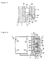
- Figure 3 is an enlarged side cross-section view of the part indicated by arrow III of Figure 1.
- Figure 4 is a side cross-section view that shows the pivot assembly of the second embodiment of the present invention.
- Figure 5 is a cross-section view of the V - V line of Figure 4.
- Figure 6 is an enlarged side cross-section view of the part indicated by arrow VI of Figure 4.
- forming a concave part that reaches up to the vicinity of the outer circumference of the outer ring, and laser welding the bottom wall of this concave part to the outer circumference of the outer ring is regarded as a suitable mode.
- this kind of mode if the laser beam is irradiated to any place on the bottom wall of the concave part, laser welding is carried out. Consequently, since the irradiation angle and the irradiation position of the laser beam do not need to be strictly controlled, laser welding can be easily carried out.
- the concave part can be made as a groove that extends along the entire circumference of the sleeve.
- welding that extends along the entire circumference of the groove can be done, or spot welding at multiple places mutually separated along the circumferential direction can be done.
- the thickness of the bottom wall be 0.1 mm or more. It is even acceptable if the concave part is holes provided mutually separated in the circumferential direction of the sleeve, and spot welding at one or two or more places of the bottom walls of those holes can also be done.
- Reference numeral 1 in these figures is a shaft.
- a hole 11 is formed in the center of the shaft 1 and, by means of a shaft passed through this hole 11; a pivot assembly is attached to a hard disk drive.
- a flange 12 is formed at the lower end part of the shaft 1. On the outer circumference of the shaft 1, the ball bearing 2 caused to contact the end face is caused to mate with the flange 12.
- a ball bearing 2 is provided with an inner ring 21 and an outer ring 22 and multiple balls 23 which can move by rolling in a circumferential direction between them.
- the balls 23 are maintained at regular intervals in a circumferential direction by means of a retainer that is not illustrated.
- the opening part between the inner ring 21 and the outer ring 22 is blocked by a seal 25.
- reference numeral 26 in the figures is a snap ring to fix the seal 25.
- a ball bearing 2 the same as mentioned above is caused to mate with the upper end part of the shaft 1. Also, a sleeve 3 is caused to mate with the outer circumference of these two ball bearings 2.
- the sleeve 3 forms a cylindrical shape, and in the center part in the axial direction thereof, a spacer part (inner wall part) 31 with an inner diameter smaller than both end parts is formed. At both end faces of the spacer part 31, the outer rings 22 of ball bearings 2 make contact, and by means of this, the outer rings 22 are separated from each other by a fixed interval.
- a groove (concave part) 32 that reaches to the vicinity of the outer circumference of the outer rings 22 is formed along the entire circumference.
- the center of the bottom wall 33 of the groove 32 is caused to correspond to the end face of the outer ring 22.
- the center of the bottom wall 33 is laser welded to the edge part of the outer ring 22 at multiple places separated at regular intervals in the circumferential direction, and, by means of this, the sleeve 3 is fixed to the outer ring 22.
- Reference numeral P in Figure 2 indicates the nugget due to welding. Furthermore, seam welding along the entire circumference of the center of the bottom wall 33 is also possible.
- a pivot assembly of the above-mentioned configuration To the outer circumference of a pivot assembly of the above-mentioned configuration the base of a swing arm provided with a magnetic head on the tip is attached. In the base of the swing arm, a hole that mates the pivot assembly is formed, and a screw passed through the above-mentioned base is screwed in a screw hole (omitted from the figure) formed in the sleeve 3.
- a groove 32 that reaches up to the vicinity of the outer circumference of the outer ring 22 is formed, and because the bottom wall 33 of this groove 32 is laser welded to the outer circumference of the outer ring 22, strictly controlling the irradiation angle and irradiation position of the laser beam is not necessary; thus, laser welding can be easily carried out. Furthermore, since the laser welding is carried out at a place furthest separated from the rolling groove of the ball bearing 2, there is no thermal effect with respect the rolling groove and balls 23, and bearing precision can be improved.
- the second embodiment of the present invention will be explained with reference to Figure 4 ⁇ Figure 6.
- the second embodiment differs from the first embodiment on the point that a hole 35 was formed, instead of the groove 32 of the first embodiment. Accordingly, in the following explanation, the same reference numerals were given to the constituent elements that are the same as those of the above-mentioned first embodiment and the explanation thereof is omitted.
- multiple holes (concave part) 35 are formed at regular intervals in a circumferential direction.
- the tip of the hole 35 forms a tapered shaped, and at this tip, an opening 36 that links to the outer circumference of the outer ring 22 is formed.
- the opening 36 is positioned in a place that approaches the ball 23 side from the end face of the outer ring 22.
- the edge part of the opening 36 is laser welded to the outer circumference of the outer ring 22 at one place or the entire circumference thereof, and by means of this, the sleeve 3 is fixed to the outer ring 22.
- the action and effect equal to that of the above-mentioned first embodiment can be obtained.
- the second embodiment there is the advantage that there is essentially no decrease in the strength of the sleeve 3, compared to the case of forming a groove 32, as in the first embodiment, because a hole 35 that links to the outer circumference of the outer ring 22 is formed.
- the sleeve is fixed by laser welding to the outer ring of a ball bearing, the sleeve can be reliably and securely fixed, moreover, the problem of out gas can be solved and the like effects can be obtained.
Landscapes
- Engineering & Computer Science (AREA)
- General Engineering & Computer Science (AREA)
- Mechanical Engineering (AREA)
- Rolling Contact Bearings (AREA)
- Mounting Of Bearings Or Others (AREA)
- Laser Beam Processing (AREA)
- Moving Of Heads (AREA)
Abstract
Description
- This application claims priority from Japanese Patent Application No. 2002-264638 filed on September 10, 2002.
- The present invention relates to an apparatus for a pivot assembly used as the bearing of a swing arm type actuator in a hard disk drive, and more particularly to the improvement of the fixing means of a sleeve that maintains the spacing of two ball bearings.
- As the above-mentioned kind of pivot assembly, for example, one that fixes ball bearings at both ends of a shaft and, in addition, mates a sleeve to the outer circumference of the ball bearings, and maintains by the bottom wall part of the sleeve a space between both ball bearings is known. This kind of pivot assembly is mated to the base part of a swing arm having a magnetic head on the tip, and is attached by means of a screw passed through the swing arm to a screw hole formed in the sleeve.
- Now, in the above-mentioned conventional pivot assembly the outer ring of the ball bearing and the sleeve were fixed by an adhesive. Because of this there was the problem that gas was generated from the adhesive and brought about a harmful effect on the surface of the hard disk and magnetic head. In order to solve this kind of out gas problem, even pressing the outer ring into a sleeve and fixing was carried out. However, with fixing by pressing in, management of the allowance for pressing in was difficult and there was the problem that the reliability of the fixing of the sleeve was deficient.
- Consequently, the present invention aims to offer a pivot assembly that can reliably and securely fix a sleeve and, in addition, can also solve the problem of out gas.
- Accordingly, the present invention is directed to a pivot assembly for hard disk drive use in which ball bearings are mated to both end parts of a shaft, and to the outer circumference of these ball bearings, an inner wall part has mated a sleeve disposed between both of the ball bearings, the sleeve is fixed by laser welding to the outer ring of the ball bearing.
- In the pivot assembly for hard disk drive use (hereinafter, called simply, "pivot assembly") of the above-mentioned configuration, because the sleeve is fixed by laser welding to the outer ring, the sleeve can be reliably and securely fixed, and, moreover, the problem of out gas can be solved.
- There is no limit on the laser source of the laser welding; for example, a YAG laser can be used. Furthermore, laser welding can be carried out across the entire circumference of the point of contact of the outer ring with the sleeve (seam weld), or can be carried out at multiple places mutually separated along the contact part (spot weld).
- Now, when welding a sleeve to the outer ring of a ball bearing, spot welding cannot be used, because with spot welding by means of electric resistance welding and gas welding, the welding part greatly lowers the bearing precision due to the thermal effect. With the present invention, because a sleeve is welded to the outer ring by means of laser welding, by narrowing the spot diameter of the laser beam to about 0.4 mm, for example, the weld part can be made smaller. By means of this the thermal effect that the weld part imparts to the outer ring is reduced and a lowering of the bearing precision can be prevented.
- Furthermore, welding of the sleeve and the outer ring can be carried out at the boundary of the end face of the outer ring and the inner circumference of the sleeve. However, because it is normal for the outer ring to have a cross-section abbreviated circular arc-shaped chamfer at the intersection of the outer circumference face and end face thereof, a concave part is formed between the edge part of the end face of the outer ring and the sleeve. In this case, the gap becomes smaller toward the inner part of the concave part, and a laser beam must correctly hit the contact part of the sleeve and outer ring positioned in the innermost part thereof. Moreover, the laser beam must irradiate so as to follow the common tangent of the chamfer and the inner circumference of the sleeve, in short, the inner circumference of the sleeve. When these points are taken into consideration, in the event the laser beam is of a small diameter as mentioned above, when the position of the sleeve fluctuates even slightly, the laser beam cannot irradiate the necessary place, and so laser welding is not easy.
- The present invention, including its features and advantages, will become more apparent from the following detailed description with reference to the accompanying drawings.
- Figure 1 is a side cross-section view that shows the pivot assembly of the first embodiment of the present invention.
- Figure 2 is a cross-section view of II - II of Figure 1.
- Figure 3 is an enlarged side cross-section view of the part indicated by arrow III of Figure 1.
- Figure 4 is a side cross-section view that shows the pivot assembly of the second embodiment of the present invention.
- Figure 5 is a cross-section view of the V - V line of Figure 4.
- Figure 6 is an enlarged side cross-section view of the part indicated by arrow VI of Figure 4.
- Accordingly, in the present invention, forming a concave part that reaches up to the vicinity of the outer circumference of the outer ring, and laser welding the bottom wall of this concave part to the outer circumference of the outer ring is regarded as a suitable mode. With this kind of mode, if the laser beam is irradiated to any place on the bottom wall of the concave part, laser welding is carried out. Consequently, since the irradiation angle and the irradiation position of the laser beam do not need to be strictly controlled, laser welding can be easily carried out. However, in order to cause the bottom wall to be welded by a laser beam narrowed as mentioned above, it is desirable that its thickness be 0.3 mm or less. Here, the concave part can be made as a groove that extends along the entire circumference of the sleeve. In this case, welding that extends along the entire circumference of the groove can be done, or spot welding at multiple places mutually separated along the circumferential direction can be done. Furthermore, in the case of forming a sleeve, in order to ensure the strength of the sleeve, it is desirable that the thickness of the bottom wall be 0.1 mm or more. It is even acceptable if the concave part is holes provided mutually separated in the circumferential direction of the sleeve, and spot welding at one or two or more places of the bottom walls of those holes can also be done.
- As another mode to make laser welding easy, on the outer circumference of a sleeve, forming holes linked to the outer circumference of the outer ring, and laser welding the edge part of these holes to the outer circumference of the outer ring, can also be done. In this case also, since laser welding can be carried out if a laser beam is irradiated to any place of the edge part of the hole, and since strict control of the irradiation angle and irradiation position of the laser beam is not necessary, laser welding can be easily carried out. Furthermore, with this kind of mode, there is also the advantage that, different from the case of forming the holes, the strength of the sleeve, practically, does not decrease.
- Carrying out the above-mentioned kind of laser welding at places separated in the axial direction from the rolling groove of the outer ring is desirable. By this means, the thermal effect on the rolling groove and balls due to the laser welding can be reduced, and the bearing precision can be improved.
- The first embodiment of the present invention will be explained with reference to Figure 1 ~ Figure 3.
Reference numeral 1 in these figures is a shaft. Ahole 11 is formed in the center of theshaft 1 and, by means of a shaft passed through thishole 11; a pivot assembly is attached to a hard disk drive. Aflange 12 is formed at the lower end part of theshaft 1. On the outer circumference of theshaft 1, the ball bearing 2 caused to contact the end face is caused to mate with theflange 12. - A ball bearing 2 is provided with an
inner ring 21 and anouter ring 22 andmultiple balls 23 which can move by rolling in a circumferential direction between them. Theballs 23 are maintained at regular intervals in a circumferential direction by means of a retainer that is not illustrated. The opening part between theinner ring 21 and theouter ring 22 is blocked by aseal 25. Furthermore,reference numeral 26 in the figures is a snap ring to fix theseal 25. - A ball bearing 2 the same as mentioned above is caused to mate with the upper end part of the
shaft 1. Also, asleeve 3 is caused to mate with the outer circumference of these twoball bearings 2. Thesleeve 3 forms a cylindrical shape, and in the center part in the axial direction thereof, a spacer part (inner wall part) 31 with an inner diameter smaller than both end parts is formed. At both end faces of the spacer part 31, theouter rings 22 ofball bearings 2 make contact, and by means of this, theouter rings 22 are separated from each other by a fixed interval. Furthermore, on the outer circumference of both end parts of thesleeve 3, a groove (concave part) 32 that reaches to the vicinity of the outer circumference of theouter rings 22 is formed along the entire circumference. The center of thebottom wall 33 of thegroove 32 is caused to correspond to the end face of theouter ring 22. And, the center of thebottom wall 33 is laser welded to the edge part of theouter ring 22 at multiple places separated at regular intervals in the circumferential direction, and, by means of this, thesleeve 3 is fixed to theouter ring 22. Reference numeral P in Figure 2 indicates the nugget due to welding. Furthermore, seam welding along the entire circumference of the center of thebottom wall 33 is also possible. - To the outer circumference of a pivot assembly of the above-mentioned configuration the base of a swing arm provided with a magnetic head on the tip is attached. In the base of the swing arm, a hole that mates the pivot assembly is formed, and a screw passed through the above-mentioned base is screwed in a screw hole (omitted from the figure) formed in the
sleeve 3. - In a pivot assembly of the above-mentioned constitution, because the
sleeve 3 is fixed by laser welding to theouter ring 22, the sleeve can be reliably and securely fixed, moreover, the problem of out gas can be solved. - In particular, in the above-mentioned first embodiment, in the outer circumference of the
sleeve 3, agroove 32 that reaches up to the vicinity of the outer circumference of theouter ring 22 is formed, and because thebottom wall 33 of thisgroove 32 is laser welded to the outer circumference of theouter ring 22, strictly controlling the irradiation angle and irradiation position of the laser beam is not necessary; thus, laser welding can be easily carried out. Furthermore, since the laser welding is carried out at a place furthest separated from the rolling groove of the ball bearing 2, there is no thermal effect with respect the rolling groove andballs 23, and bearing precision can be improved. - Next, the second embodiment of the present invention will be explained with reference to Figure 4 ~ Figure 6. The second embodiment differs from the first embodiment on the point that a
hole 35 was formed, instead of thegroove 32 of the first embodiment. Accordingly, in the following explanation, the same reference numerals were given to the constituent elements that are the same as those of the above-mentioned first embodiment and the explanation thereof is omitted. - As shown in the figure, on the outer circumference of both end parts of the
sleeve 3, multiple holes (concave part) 35 are formed at regular intervals in a circumferential direction. The tip of thehole 35 forms a tapered shaped, and at this tip, anopening 36 that links to the outer circumference of theouter ring 22 is formed. Theopening 36 is positioned in a place that approaches theball 23 side from the end face of theouter ring 22. And, the edge part of theopening 36 is laser welded to the outer circumference of theouter ring 22 at one place or the entire circumference thereof, and by means of this, thesleeve 3 is fixed to theouter ring 22. - In the second embodiment also the action and effect equal to that of the above-mentioned first embodiment can be obtained. Particularly, in the second embodiment, there is the advantage that there is essentially no decrease in the strength of the
sleeve 3, compared to the case of forming agroove 32, as in the first embodiment, because ahole 35 that links to the outer circumference of theouter ring 22 is formed. - According to the present invention as explained above, because a sleeve is fixed by laser welding to the outer ring of a ball bearing, the sleeve can be reliably and securely fixed, moreover, the problem of out gas can be solved and the like effects can be obtained.
- In the foregoing description, the apparatus and method of the present invention have been described with reference to specific examples. It is to be understood and expected that variations in the principles of the apparatus and method herein disclosed may be made by one skilled in the art and it is intended that such modifications, changes, and substitutions are to be included within the scope of the present invention as set forth in the appended claims. The specification and drawings are accordingly to be regarded in an illustrative rather than in a restrictive sense.
Claims (6)
- An apparatus for a pivot assembly for hard disk drive use comprising:a pivot assembly for hard disk drive use in which ball bearings have been mated with both ends of a shaft; andan inner wall part, at the outer circumference of these ball bearings, has mated a sleeve disposed between both of said ball bearings,wherein sleeve is fixed by means of laser welding to the outer rings of said ball bearings.
- The apparatus according to claim 1, wherein on the outer circumference of said sleeve a concave part that reaches up to the vicinity of the outer circumference of said outer ring is formed, and the bottom wall of this concave part is laser welded with the outer circumference of said outer ring.
- The apparatus according to claim 2, wherein the concave part is a groove that extends along the entire circumference of said sleeve.
- The apparatus according to claim 2, wherein the concave part is holes provided separated from each other in the circumferential direction of said sleeve.
- The apparatus according to any preceding claim, wherein on the outer circumference of said sleeve, a hole linked to the outer circumference of said outer ring is formed, and the edge part of this hole is laser welded to the outer circumference of said outer ring.
- The apparatus according to claim 5, wherein said laser welding is carried out at places separated in the axial direction from the rolling groove of said outer ring.
Applications Claiming Priority (2)
| Application Number | Priority Date | Filing Date | Title |
|---|---|---|---|
| JP2002264638A JP2004100850A (en) | 2002-09-10 | 2002-09-10 | Pivot assembly for hard disc drive |
| JP2002264638 | 2002-09-10 |
Publications (2)
| Publication Number | Publication Date |
|---|---|
| EP1403856A2 true EP1403856A2 (en) | 2004-03-31 |
| EP1403856A3 EP1403856A3 (en) | 2006-05-10 |
Family
ID=31973188
Family Applications (1)
| Application Number | Title | Priority Date | Filing Date |
|---|---|---|---|
| EP03255658A Withdrawn EP1403856A3 (en) | 2002-09-10 | 2003-09-10 | Pivot assembly |
Country Status (3)
| Country | Link |
|---|---|
| US (1) | US6995955B2 (en) |
| EP (1) | EP1403856A3 (en) |
| JP (1) | JP2004100850A (en) |
Cited By (2)
| Publication number | Priority date | Publication date | Assignee | Title |
|---|---|---|---|---|
| CN102141088A (en) * | 2010-01-29 | 2011-08-03 | 美蓓亚株式会社 | Bearing device |
| WO2019048123A1 (en) * | 2017-09-11 | 2019-03-14 | Robert Bosch Gmbh | FIXED BEARINGS FOR A STEERING GEAR AND METHOD FOR PRODUCING THE FIXED BEARINGS |
Families Citing this family (7)
| Publication number | Priority date | Publication date | Assignee | Title |
|---|---|---|---|---|
| JP2004076901A (en) * | 2002-08-21 | 2004-03-11 | Minebea Co Ltd | Pivot assembly for hard disk drive |
| US8579514B2 (en) * | 2010-04-26 | 2013-11-12 | Seagate Technology Llc | Press fitting a cartridge bearing |
| US9140304B2 (en) * | 2010-04-29 | 2015-09-22 | Aktiebolaget Skf | Rolling bearing arrangement |
| JP2011256966A (en) * | 2010-06-10 | 2011-12-22 | Seiko Instruments Inc | Rolling bearing, bearing device and information recording and reproducing device |
| US9542964B2 (en) * | 2014-10-28 | 2017-01-10 | Minebea Co., Ltd. | Pivot assembly bearing and hard disk drive device |
| JP2017116069A (en) * | 2015-12-25 | 2017-06-29 | セイコーインスツル株式会社 | Bearing device, information recording/reproducing apparatus and method of manufacturing bearing device |
| US20210254694A1 (en) * | 2018-06-13 | 2021-08-19 | Exedy Globalparts Corporation | Hydrodynamic launch device with anti-expansion feature |
Family Cites Families (10)
| Publication number | Priority date | Publication date | Assignee | Title |
|---|---|---|---|---|
| US5161077A (en) * | 1990-11-09 | 1992-11-03 | Seagate Technology, Inc. | Actuator arm with a steel sleeve for thermal off track compensation |
| CA2055060C (en) * | 1990-12-31 | 1996-04-16 | John R. Reidenbach | Rotary actuator for disk drive assemblies |
| US5529404A (en) * | 1994-06-01 | 1996-06-25 | Seagate Technology, Inc. | Adhesiveless assembly with laser welding |
| US5482381A (en) * | 1994-06-16 | 1996-01-09 | Seagate Technology, Inc. | Actuator assembly having labyrinth seal |
| US6018441A (en) * | 1998-06-08 | 2000-01-25 | Read-Rite Corporation | Disk drive pivot bearing and actuator arm assembly |
| GB2367337B (en) * | 1999-06-24 | 2003-11-12 | Seagate Technology Llc | Actuator bearing cartridge for disc storage system |
| JP2001065556A (en) * | 1999-08-26 | 2001-03-16 | Minebea Co Ltd | Pivot assembly |
| US6631053B1 (en) * | 1999-09-28 | 2003-10-07 | Maxtor Corporation | Actuator pivot assembly that pivotally connects an actuator to a base of a disk drive |
| US6519116B1 (en) * | 2000-11-30 | 2003-02-11 | Western Digital Technologies, Inc. | Actuator arm assembly having bearing gap formed between bearing outer race and pivot sleeve for mitigating torque ripple on actuator arm in a disk drive |
| US6687092B2 (en) * | 2001-05-10 | 2004-02-03 | Hitachi Global Storage Technologies Netherland B.V. | Pivot bearing assembly for compensating for disk drive actuator tilt |
-
2002
- 2002-09-10 JP JP2002264638A patent/JP2004100850A/en not_active Withdrawn
-
2003
- 2003-09-05 US US10/656,740 patent/US6995955B2/en not_active Expired - Fee Related
- 2003-09-10 EP EP03255658A patent/EP1403856A3/en not_active Withdrawn
Cited By (2)
| Publication number | Priority date | Publication date | Assignee | Title |
|---|---|---|---|---|
| CN102141088A (en) * | 2010-01-29 | 2011-08-03 | 美蓓亚株式会社 | Bearing device |
| WO2019048123A1 (en) * | 2017-09-11 | 2019-03-14 | Robert Bosch Gmbh | FIXED BEARINGS FOR A STEERING GEAR AND METHOD FOR PRODUCING THE FIXED BEARINGS |
Also Published As
| Publication number | Publication date |
|---|---|
| JP2004100850A (en) | 2004-04-02 |
| US6995955B2 (en) | 2006-02-07 |
| EP1403856A3 (en) | 2006-05-10 |
| US20040136116A1 (en) | 2004-07-15 |
Similar Documents
| Publication | Publication Date | Title |
|---|---|---|
| US7341379B2 (en) | Pivot assembly for hard disk drive use | |
| US7072148B2 (en) | Apparatus for the sealing of a pivot assembly used in a hard disk drive | |
| US20040136116A1 (en) | Pivot assembly for hard disk drive use | |
| EP1323488A2 (en) | Electrode for welding | |
| US7367487B2 (en) | Method for friction stir welding, jig therefor, member with friction stir-welded portion, and tool for friction stir welding | |
| JP4730095B2 (en) | Roller bearing cage | |
| JP2000213551A (en) | End piece pressure contact type hollow camshaft | |
| JPH06300046A (en) | Bearing device for supporting shaft or axle in support section | |
| JPH08338436A (en) | Fixing method into hole of mounting plate made of metal of shaft support bush made of material incapable of being welded | |
| HK1065158A (en) | Pivot assembly | |
| US20040170349A1 (en) | Ultrathin-walled rolling bearing and cage therefor | |
| US20100288736A1 (en) | Weld stud | |
| US7136262B2 (en) | Pivot assembly preloaded by laser welding for hard disk drive use | |
| KR101583174B1 (en) | Back-shielded welding method and welded structure using same | |
| JP2004092668A (en) | Manufacturing method of pivot assembly for hard disk drive and preload setting device therefor | |
| JP3184408B2 (en) | Welded structure | |
| EP2101036B1 (en) | A method for reducing residual stress in a roller cone bit | |
| HK1064201A (en) | Pivot assembly for the positioning arm of a hard disk drive | |
| HK1063527A (en) | Pivot assembly for hard disk drive use | |
| JP3252241U (en) | Welding bolts | |
| JP5465970B2 (en) | Rolling bearing device | |
| JP2022140118A (en) | welding bolt | |
| EP2231358A1 (en) | Weld stud | |
| KR20010076270A (en) | Welding construction | |
| HK1063873A (en) | Method of manufacture and apparatus for a pivot assembly |
Legal Events
| Date | Code | Title | Description |
|---|---|---|---|
| PUAI | Public reference made under article 153(3) epc to a published international application that has entered the european phase |
Free format text: ORIGINAL CODE: 0009012 |
|
| AK | Designated contracting states |
Kind code of ref document: A2 Designated state(s): AT BE BG CH CY CZ DE DK EE ES FI FR GB GR HU IE IT LI LU MC NL PT RO SE SI SK TR |
|
| AX | Request for extension of the european patent |
Extension state: AL LT LV MK |
|
| REG | Reference to a national code |
Ref country code: HK Ref legal event code: DE Ref document number: 1065158 Country of ref document: HK |
|
| PUAL | Search report despatched |
Free format text: ORIGINAL CODE: 0009013 |
|
| AK | Designated contracting states |
Kind code of ref document: A3 Designated state(s): AT BE BG CH CY CZ DE DK EE ES FI FR GB GR HU IE IT LI LU MC NL PT RO SE SI SK TR |
|
| AX | Request for extension of the european patent |
Extension state: AL LT LV MK |
|
| RIC1 | Information provided on ipc code assigned before grant |
Ipc: G11B 19/20 20060101ALI20060321BHEP Ipc: G11B 5/48 20060101AFI20040108BHEP |
|
| AKX | Designation fees paid | ||
| 17P | Request for examination filed |
Effective date: 20060928 |
|
| RBV | Designated contracting states (corrected) |
Designated state(s): DE FR GB |
|
| REG | Reference to a national code |
Ref country code: DE Ref legal event code: 8566 |
|
| 17Q | First examination report despatched |
Effective date: 20070301 |
|
| GRAP | Despatch of communication of intention to grant a patent |
Free format text: ORIGINAL CODE: EPIDOSNIGR1 |
|
| STAA | Information on the status of an ep patent application or granted ep patent |
Free format text: STATUS: THE APPLICATION IS DEEMED TO BE WITHDRAWN |
|
| 18D | Application deemed to be withdrawn |
Effective date: 20080815 |
|
| REG | Reference to a national code |
Ref country code: HK Ref legal event code: WD Ref document number: 1065158 Country of ref document: HK |