EP1403726A2 - Electrostatic developing toner - Google Patents
Electrostatic developing toner Download PDFInfo
- Publication number
- EP1403726A2 EP1403726A2 EP03256017A EP03256017A EP1403726A2 EP 1403726 A2 EP1403726 A2 EP 1403726A2 EP 03256017 A EP03256017 A EP 03256017A EP 03256017 A EP03256017 A EP 03256017A EP 1403726 A2 EP1403726 A2 EP 1403726A2
- Authority
- EP
- European Patent Office
- Prior art keywords
- toner
- iron oxide
- silica
- image
- particle diameter
- Prior art date
- Legal status (The legal status is an assumption and is not a legal conclusion. Google has not performed a legal analysis and makes no representation as to the accuracy of the status listed.)
- Granted
Links
Images




Classifications
-
- G—PHYSICS
- G03—PHOTOGRAPHY; CINEMATOGRAPHY; ANALOGOUS TECHNIQUES USING WAVES OTHER THAN OPTICAL WAVES; ELECTROGRAPHY; HOLOGRAPHY
- G03G—ELECTROGRAPHY; ELECTROPHOTOGRAPHY; MAGNETOGRAPHY
- G03G9/00—Developers
- G03G9/08—Developers with toner particles
- G03G9/083—Magnetic toner particles
- G03G9/0838—Size of magnetic components
-
- G—PHYSICS
- G03—PHOTOGRAPHY; CINEMATOGRAPHY; ANALOGOUS TECHNIQUES USING WAVES OTHER THAN OPTICAL WAVES; ELECTROGRAPHY; HOLOGRAPHY
- G03G—ELECTROGRAPHY; ELECTROPHOTOGRAPHY; MAGNETOGRAPHY
- G03G9/00—Developers
- G03G9/08—Developers with toner particles
- G03G9/083—Magnetic toner particles
- G03G9/0835—Magnetic parameters of the magnetic components
Definitions
- This invention relates to an electrostatic developing toner used in an image-forming apparatus such as a printer, copier or facsimile machine which forms an image by developing an electrostatic latent image formed on a photoconductive layer of a photoconductive drum using a toner, i.e. by an electrophotographic method.
- an electrostatic developing toner which can effectively suppress fogging of the image by setting a ratio (d/D) between a toner average particle diameter D and an average particle diameter d of iron oxide particles contained in the toner which function as a colorant, or by setting a ratio ( ⁇ r/ ⁇ s) between a residual magnetization ⁇ r and a saturation magnetization ⁇ s of the iron oxide particles.
- It further relates to an electrostatic developing toner which can suppress the cracking amount of the photoconductive layer on the photoconductive drum accompanying the formation of the image even after about 10000 images have been formed.
- JP Laid-open Patent Publication No. 05-341556 discloses a toner used in an image-forming apparatus wherein an electrostatic latent image is formed on a photoconductive layer of a latent image carrier via an optical source such as a laser, and toner is supplied to the electrostatic latent image from a toner carrier in contact with the latent image carrier to develop the electrostatic latent image.
- This toner is a one-component toner containing 20-50wt% of iron oxide in a binder resin containing a colorant such as carbon black.
- JP Laid-open Patent Publication No. 11-143121 discloses a toner used in an image-forming apparatus wherein an electrostatic latent image is formed on a photoconductive layer of an electrostatic latent image carrier, and the electrostatic latent image is developed by supplying toner from a developer carrier (developing roller).
- This toner contains a magnetic powder having a saturation magnetization ⁇ s of 5A.m 2 /kg or less, and a residual magnetization ⁇ r of 3A.m 2 /kg or less.
- magnetic powders such as metal oxides are added to the toner for various purposes such as suppressing image fogging
- JP Laid-open Patent Publication No. 05-341556 states that the iron oxide content of the toner is 20-50wt%, no mention is made of the other magnetic properties of the iron oxide.
- JP Laid-open Patent Publication No. 11-143121 discloses that the magnetic powder added to the toner has a saturation magnetization ⁇ s of 5A.m 2 /kg or less, and a residual magnetization ⁇ r of 3A.m 2 /kg or less, however as in the case of No. 05-341556, no mention is made of the other magnetic properties of the magnetic powder.
- JP Laid-open Patent Publication No. 11-194557 discloses an image-forming apparatus wherein a good image exposure is obtained according to a film pressure of an outermost layer of a photoconductive drum by inputting data relating to the photoconductive drum drive time and the time during which a voltage is applied to the charging roller, together with data relating to the contact pressure of a cleaning blade on a photoconductive drum from a non-volatile memory, calculating a film thickness of the outermost layer of the photoconductive drum based on this data in a control unit, and controlling the image exposure of an exposure apparatus on the photoconductive drum based on the calculated film thickness of the photoconductive drum.
- the first factor is that a contact charging method is used wherein a charging roller is brought into contact with the photoconductive drum to charge the outer circumferential surface of the photoconductive drum, and the photoconductive layer on the photoconductive drum may be scraped by the charging roller when the image is formed.
- a residual toner removal method is used wherein a cleaning blade is brought into pressure contact with the photoconductive layer surface on the photoconductive drum to remove residual toner on the photoconductive drum surface after transfer of the toner image to a transfer material, and the photoconductive layer on the photoconductive drum may be scraped by the cleaning blade.
- the colorant contained in the toner particles of the electrostatic latent image toner is a particulate pigment
- its particle size and amount in the toner must be considered as possible factors in the scraping of the photoconductive layer, and if silica particulates are added to the toner particles, their particle size and addition amounts must also be considered.
- the inventors also arrived at the present invention after intensive studies undertaken by performing experiments on the effect of components of electrostatic developing toners on the scraping of the photoconductive layer on the photoconductive drum. It is therefore a further object of this invention to provide an electrostatic developing toner which can suppress the scraping amount of the photoconductive layer on the photoconductive drum when an image is formed, to a constant value or less, even after about 10000 images are formed.
- the toner according to a first aspect of the invention is an electrostatic developing toner used in an image-forming apparatus wherein an electrostatic latent image is formed on a photoconductive layer formed on a circumferential surface of a photoconductive drum, and the electrostatic latent image is developed by supplying toner to the electrostatic latent image from a non-magnetic developing roller brought into contact with the photoconductive drum, wherein this electrostatic developing toner contains iron oxide particles in resin particles, and the ratio (d/D) between the average particle diameter D of the electrostatic developing toner and average particle diameter d of the iron oxide particles is within the range 0. 01-0. 03.
- the ratio (d/D) between the average particle diameter D of the electrostatic developing toner and average particle diameter d of the iron oxide particles is set within the range 0.01-0.03, so image fogging is effectively suppressed. If the value of the aforesaid ratio (d/D) departs from this range, image fogging increases.
- the electrostatic developing toner according to a second aspect of the invention is an electrostatic developing toner used in an image-forming apparatus wherein an electrostatic latent image is formed on a photoconductive layer formed on a circumferential surface of a photoconductive drum, and the electrostatic latent image is developed by supplying toner to the electrostatic latent image from a non-magnetic developing roller brought into contact with the photoconductive drum, wherein this electrostatic developing toner contains iron oxide particles in resin particles, the iron oxide particles have a retentivity Hc of 3-7 kA/m in a magnetic field of 79. 6kA/m, and the ratio ( ⁇ r/ ⁇ s) between their residual magnetization ⁇ r and saturation magnetization ⁇ s is 0.3 or less.
- the iron oxide particles have a retentivity Hc of 3-7kA/m in a magnetic field of 79.6kA/m, and the ratio ( ⁇ r/ ⁇ s) of the residual magnetization ⁇ r and saturation magnetization ⁇ s in the iron oxide particles is 0.3 or less. Therefore, in a non-magnetic developing process which uses a non-magnetic developing roller, if the residual magnetization ⁇ r is small even if the saturation magnetization ⁇ s is high, the magnetic cohesive force between toner particles is weak and cohesion between toner particles can be prevented.
- the electrostatic latent image can be developed without impairing toner fluid properties. As a result, image fogging can be effectively suppressed.
- the electrostatic developing toner according to a third aspect of the invention is an electrostatic developing toner used in an image-forming apparatus wherein an electrostatic latent image is formed on a photoconductive layer having a film thickness of 30-50 ⁇ m formed on the circumferential surface of a photoconductive drum, and toner is supplied to the electrostatic latent image from a developing roller in contact.with the photoconductive drum at a nip pressure of 50-350kPa to develop the electrostatic latent image.
- This electrostatic developing toner contains a colorant in resin particles with the addition of at least one of a first silica particulate and a second silica particulate having mutually different particle diameters.
- the colorant is iron oxide having a particle diameter in the range 0.1-0.6 ⁇ m, and its addition amount is 5-10vol% relative to toner.
- the average value of the BET specific surface area is in the range 50-150m 2 /g, and its addition amount is 0.3-2wt%.
- the average value of the BET specific surface area is in the range 20-100m 2 /g, and its addition amount is 0.5-2wt%.
- the nip pressure of the developing roller on the photoconductive drum is set to the range 50-350kPa, and images are formed using the electrostatic developing toner prepared above, the scraping amount of the photoconductive layer of the photoconductive drum after about 10000 images have been formed, can be suppressed to 20-40 ⁇ m or less. As a result, even after about 10000 images have been formed, the film thickness of the photoconductive layer can be maintained at 10 ⁇ m or more, and images can be formed continuously.
- the film thickness of the photoconductive layer is less than 10 ⁇ m, image fogging increases as the film thickness decreases, and as a suitable image can then no longer be obtained, it is required that the photoconductive layer has a film thickness of 10 ⁇ m or more in order to form a proper image.
- Fig. 1 is a perpendicular cross-sectional view of a laser printer
- Fig. 2 is an enlarged lateral view of the developing unit and photoconductive drum part of the laser printer.
- a laser printer 1 comprises a main case 2, a feeder unit 10 for feeding a paper P which is a recording medium for forming an image, a photoconductive drum 20 which is a photoconductive medium for performing the steps of charging to form an image, exposure, developing, transfer and recovery in sequence, a fixing unit 70 for fixing an image transferred from the photoconductive drum 20 to the paper P on the paper P, and a paper eject tray 77 for ejecting the paper P on which the image is fixed along a paper transport path PP.
- the laser printer 1 comprises a drive means, not shown, for rotating the photoconductive drum 20.
- a laser scanner unit 30 for forming an electrostatic latent image on the photoconductive drum 20 rotated by the drive means a developing unit 50 comprising a developing roller 56 for developing the electrostatic latent image formed on the photoconductive drum 20 by a toner, a transfer roller 60 for transferring the toner image developed on the photoconductive drum 20 to the paper P, a discharge lamp 41 for discharging residual potential remaining on the photoconductive drum 20 after transfer, a cleaning roller 42 for temporarily adsorbing residual toner and then discharging and leveling it on the photoconductive drum 20 after charge has been eliminated by the discharge lamp 41, so that residual toner remaining on the photoconductive drum 20 after transfer by the transfer roller 60 is returned to the developing unit 50 at a predetermined timing using the photoconductive drum 20, and a charger 40 for charging the photoconductive drum 20 so that it can form an electrostatic latent image after discharging and leveling, are disposed in sequence around the photoconductive drum 20.
- the feeder unit 10 further comprises a paper pressure plate 11 disposed inside the feeder case 3 situated above the rear end of the main case 2 having substantially identical width dimensions to those of the paper P.
- the paper pressure plate 11 is supported free to oscillate at its rear end.
- a compression spring 12 is provided at the front end of the paper pressure plate 11, the paper pressure plate 11 being pushed upwards elastically by this compression spring 12.
- the paper pressure plate 11 supports a paper feed roller 13 extending to the left and right such that it is free to rotate.
- the paper feed roller 13 is rotation driven with the paper feed timing by a drive system, not shown.
- the feeder unit 10 houses a paper feed cassette 14 set in the feeder case 3 such that it can be freely inserted or removed obliquely, and which can accommodate plural sheets of the paper P cut to fixed dimensions.
- the feeder unit 10 comprises a separating member 15 below the paper feed roller 13, this separating member 15 being pushed elastically against the paper feed roller 13 by a compression spring 16.
- a pair of resist rollers 17, 18 which grip the front edge of the paper P are respectively supported free to rotate downstream in the transport direction (in Fig. 1, from the back to the front) from the paper feed roller 13.
- the photoconductive drum 20 comprises a positive charge material, for example an organic photoconductive material having a positive charge polycarbonate, as its main component.
- the photoconductive drum 20 is a hollow drum which is cylindrical, comprising a photoconductive layer 22 of a predetermined thickness (e.g., the initial thickness is 30-15 ⁇ m) comprising a photoconductive resin dispersed in polycarbonate on the outer circumference of an aluminum cylindrical sleeve 21, and is supported free to rotate in the main case 2 such that the cylindrical sleeve 21 is earthed.
- the electrostatic latent image which has positive polarity (positive charge) formed on the photoconductive drum 20 is developed by developing the positive charge toner by the reverse developing method.
- the photoconductive drum 20 is rotation driven in the clockwise direction, viewed laterally, by a drive means.
- the laser scanner unit 30 is disposed below the photoconductive drum 20, and comprises a laser imaging apparatus 31 which emits a laser L for forming an electrostatic latent image on the photoconductive drum 20, a polygon mirror (5 facepiece mirror) 32 which is rotation driven, a pair of lenses 33, 34, and a pair of reflecting mirrors 35, 36.
- the charger 40 for example is a scorotron charger for positive charging which generates a corona discharge from a charging wire, for example of tungsten.
- a cleaneriess method is adopted wherein the charger 40 is disposed facing the photoconductive drum 20 but not in contact with it, so that residual toner on the photoconductive drum 20 does not adhere to the charger 40.
- the discharge lamp 41 inside the main case 2 for example comprises a light source such as a LED (light emitting diode), EL (electroluminescence) or a neon lamp, and the charge remaining on the photoconductive drum 20 after transfer is removed (discharged) by irradiating with a light Le.
- a light source such as a LED (light emitting diode), EL (electroluminescence) or a neon lamp
- the cleaning roller 42 varies a bias voltage so that, in a suction mode, the residual toner 53 remaining on the photoconductive drum 20 after transfer by the transfer roller 60 is first aspirated, and in a discharge mode, the aspirated residual toner 53 is discharged and leveled over the photoconductive drum 20 at a timing which does not interfere with the subsequent exposure, developing and transfer on the photoconductive drum 20. By these actions, the residual toner 53 is returned from the photoconductive drum 20 to the developing unit 50.
- This cleaning roller 42 may for example be a foam elastic body having electrical conductivity comprising silicone rubber or urethane rubber which permits a bias voltage to be applied.
- the cleaning roller 42 is in contact with the photoconductive drum 20, and as described above, as it comprises a foam elastic body such as silicone rubber or urethane rubber, friction with the photoconductive drum 20 is reduced, and the photoconductive layer 22 on the photoconductive drum 20 is not scraped when cleaning is performed.
- a foam elastic body such as silicone rubber or urethane rubber
- the developing unit 50 comprises a double cylindrical toner box 51 housed in a developer case 4 such that it can be freely inserted or removed.
- the toner box 51 houses an agitator 52 which is rotation driven, and the positive charge toner 53 which has electrical insulating properties.
- a toner chamber 54 which accommodates the toner 53 supplied due to the rotation of the agitator 52 via a toner supplied port 51a formed in the toner box 51, is formed.
- the toner chamber 54 houses a supply roller 55 disposed horizontally in its longitudinal direction, and which is supported free to rotate.
- the developing roller 56 which is also disposed horizontally in its longitudinal direction and supported free to rotate, partitions the front of the toner chamber 54 and is in contact with the supply roller 55 and photoconductive drum 20.
- the supply roller 55 comprises a foam elastic body having electrical conductivity comprising silicone rubber or urethane rubber.
- the developing roller 56 forms a nip N due to contact with the photoconductive drum 20 as shown in Fig. 2, and is also an electrically conducting rigid roller comprising silicone rubber or urethane rubber.
- the laser printer 1 of this aspect of the invention for example uses the photoconductive drum 20 comprising an organic photoconductive material having positive charge toner and positive charge polycarbonate as its main components, and urethane rubber is the material of the developing roller 56.
- the photoconductive drum 20 is rotated clockwise and the developing roller 56 is also rotated clockwise.
- a rotation direction of the photoconductive drum 20 and that of the developing roller 56 are opposite to each other at the nip N.
- amount of toner 53 the developing roller 56 can deliver to the photoconductive drum 20 becomes larger.
- This mechanism can make layer thickness of toner 53 carried onto the developing roller 56 thin. Therefore, toner 53 can be charged uniformly and image quality can be improved.
- the nip pressure (contact pressure) of the developing roller 56 with the photoconductive drum 20 is set within the range 50-350kPa. If this nip pressure falls below 50kPa, the offset of the developing roller 56 appears directly in the image, and gives rise to image distortion. Conversely, if the nip measure is more than 350kPa, the torque which drives the developing roller 56 is excessive, and interferes with the drive.
- the toner chamber 54 is provided in the developer case 4 in the developing unit 50, this toner chamber 54 being formed such that there is a large upper gap S above the supply roller 55.
- a layer thickness regulating blade 57 comprised of a thin stainless steel or copper plate with elasticity is installed facing downwards in the developer case 4.
- a curved part 57a formed at the bottom of the layer thickness regulating blade 57 is in contact with the developing roller 56 such that it presses against it, and the layer thickness of the toner 53 supplied from the supply roller 55 and adhering as a layer to the surface of the developing roller 56, is regulated by this layer thickness regulating blade 57 to a predetermined thickness (approximately 7-12 ⁇ m).
- the transfer roller 60 which is installed in contact with the upper side of the photoconductive drum 20 and is supported free to rotate, comprises a foam elastic body having electrical conductivity comprising silicone rubber or urethane rubber.
- the fixing unit 70 which is installed downstream of the photoconductive drum 20 in the transport direction, and comprises a heating roller 71 and pressure roller 72 housing a halogen lamp known in the art, fixes the toner image transferred to the underside of the paper P by heat and pressure so as to fix it on the paper P.
- a pair of transport rollers 75 for transporting the paper and the paper eject tray 77 are respectively installed downstream of the fixing unit 70 in the transport direction.
- the paper supply roller 13, photoconductive drum 20, fixing unit 70 and paper eject tray 77 transport the paper P supplied from the paper cassette 14 along the substantially linear paper transport path PP.
- the toner according to present aspect of the invention is a positive charge toner, for example a non-magnetic one component toner comprising a polymer resin of styrene acrylate or the like, the proportion of iron oxide having substantially spherical particles which functions as a colorant in the polymer resin toner particles is 4-7vol% relative to toner, and various additives such as two types of silica particulates having different particle sizes to confer fluidity, and a wax and a charge controlling agent, are added.
- a positive charge toner for example a non-magnetic one component toner comprising a polymer resin of styrene acrylate or the like, the proportion of iron oxide having substantially spherical particles which functions as a colorant in the polymer resin toner particles is 4-7vol% relative to toner, and various additives such as two types of silica particulates having different particle sizes to confer fluidity, and a wax and a charge controlling agent, are added.
- a powdered toner may also be used.
- the toner can be uniformly charged unlike the case where they have different shapes, and image fogging can be effectively suppressed.
- the iron oxide particles which act as a colorant account for 4-7vol% of the toner, image fogging is suppressed and the image can be formed with a suitable print density. If the iron oxide particle content is within the range 4-7vol%, the scraping amount of the photoconductive layer of the photoconductive drum due to the iron oxide particles in image-forming can be suppressed to within tolerance limits.
- Examples 1-4, Comparative Examples 1, 2) six types of iron oxide particles having different retentivity Hc, saturation magnetization ⁇ s, residual magnetization ⁇ r and average particle diameter d were manufactured, six types of toner containing these iron oxide particles were prepared (Examples 1-4, Comparative Examples 1, 2), and the fogging value in the initial stage of image-forming and the fogging value after printing 6000 sheets were measured for each toner.
- the retentivity Hc, saturation magnetization ⁇ s, residual magnetization ⁇ r and average particle diameter d of the iron oxide particles used in the toners of Examples 1-4, and Comparative Examples 1, 2, and the toner average particle diameter D measured for each toner, are listed in the following Table 1.
- Table 1 shows the physical properties for the iron oxide particles used in the toner of Example 1.
- the retentivity Hc measured at a measured magnetic field of 1kOe (97.6kA/m) was 4.70kA/m (59eO).
- the saturation magnetization ⁇ s was 66.7Am 2 /kg, and the residual magnetization ⁇ r was 5Am 2 /kg. Hence, the ratio ( ⁇ r/ ⁇ s) of the residual magnetization ⁇ r and saturation magnetization ⁇ s was 0.07.
- the average particle diameter d of iron oxide particles was 0.22 ⁇ m.
- the average particle diameter D of the final toner was 9.155 ⁇ m.
- the ratio (d/D) of the average particle diameter d of iron oxide particles to the average particle diameter D of toner was 0.024.
- the initial fogging value when images were first formed was 0. 35, and the fogging value after 6000 sheets had been printed was 1.01.
- the fogging value must be 2.0 or less.
- the fogging value measured for the toner in Example 1 was within the permitted range for both the initial value and after printing 6000 sheets, and fogging was suppressed.
- Table 1 shows various physical properties for the iron oxide particles used in the toner of Example 2.
- the retentivity Hc measured at a measured magnetic field of 1kOe was 6.77kA/m (85eO).
- the saturation magnetization ⁇ s was 65Am 2 /kg, and the residual magnetization ⁇ r was 8 . 7 Am 2 /kg. Hence, the ratio ( ⁇ r/ ⁇ s) of the residual magnetization ⁇ r and saturation magnetization ⁇ s was 0.13.
- the average particle diameter d of iron oxide particles was 0.13 ⁇ m.
- the average particle diameter D of the final toner was 9.220 ⁇ m.
- the ratio (d/D) of the average particle diameter d of iron oxide particles to the average particle diameter D of toner was 0.014.
- the initial fogging value when images were first formed was 1.13
- the fogging value after 6000 sheets had been printed was 1.29.
- the fogging value must be 2.0 or less.
- the fogging value measured for the toner in Example 2 was within the permitted range for both the initial value and after printing 6000 sheets, and fogging was suppressed.
- Table 1 shows various physical properties of the iron oxide particles used in the toner of Example 3.
- the retentivity Hc measured at a measured magnetic field of 1kOe was 7.40kA/m (93eO).
- the saturation magnetization ⁇ s was 66Am 2 /kg, and the residual magnetization ⁇ r was 9.3Am 2 /kg. Hence, the ratio ( ⁇ r/ ⁇ s) of the residual magnetization ⁇ r and saturation magnetization ⁇ s was 0.14.
- the average particle diameter d of iron oxide particles was 0.22 ⁇ m.
- the average particle diameter D of the final toner was 8.907 ⁇ m.
- the ratio (d/D) of the average particle diameter d of iron oxide particles to the average particle diameter D of toner was 0. 021.
- the initial fogging value when images were first formed was 0.56
- the fogging value after 6000 sheets had been printed was 1.03.
- the fogging value must be 2.0 or less.
- the fogging value measured for the toner in Example 3 is within the permitted range for both the initial value and after printing 6000 sheets, and fogging is suppressed.
- Table 1 shows various physical properties of the iron oxide particles used in the toner of Example 4.
- the retentivity Hc measured at a measured magnetic field of 1kOe was 9.07kA/m (114eO).
- the saturation magnetization ⁇ s was 59.6Am 2 /kg, and the residual magnetization ⁇ r was 10Am 2 /kg. Hence, the ratio ( ⁇ r/ ⁇ s) of the residual magnetization ⁇ r and saturation magnetization as was 0.17.
- the average particle diameter d of iron oxide particles was 0.23 ⁇ m.
- the average particle diameter D of the final toner was 9.041 ⁇ m.
- the ratio (d/D) of the average particle diameter d of iron oxide particles to the average particle diameter D of toner was 0.025.
- the initial fogging value when images were first formed was 1.17
- the fogging value after 6000 sheets had been printed was 1.20.
- the fogging value must be 2.0 or less.
- the fogging value measured for the toner in Example 4 is within the permitted range for both the initial value and after printing 6000 sheets, and fogging is suppressed.
- Table 1 shows various physical properties of the iron oxide particles used in the toner of Comparative Example 1.
- the retentivity Hc measured at a measured magnetic field of 1kOe was 22.5kA/m (283eO).
- the saturation magnetization ⁇ s was 0.6m 2 /kg, and the residual magnetization ⁇ r was 0.2Am 2 /kg. Hence, the ratio ( ⁇ r/ ⁇ s) of the residual magnetization ⁇ r and saturation magnetization ⁇ s was 0.33.
- the average particle diameter d of iron oxide particles was 0.3 ⁇ m.
- the average particle diameter D of the final toner was 8.832 ⁇ m.
- the ratio (d/D) of the average particle diameter d of iron oxide particles to the average particle diameter D of toner was 0.034.
- the initial fogging value when images were first formed was 2.39
- the fogging value after 6000 sheets had been printed was 3.11.
- the fogging value must be 2.0 or less.
- the fogging value measured for the toner in Comparative Example 1 largely departs from the permitted range for both the initial value and after printing 6000 sheets, and fogging is not sufficiently suppressed.
- Table 1 shows various physical properties of the iron oxide particles used in the toner of Comparative Example 2.
- the retentivity Hc measured at a measured magnetic field of 1kOe was 4.62kA/m (58eO).
- the saturation magnetization ⁇ s was 0.2Am 2 /kg, and the residual magnetization ⁇ r was 0.1Am 2 /kg. Hence, the ratio ( ⁇ r/ ⁇ s) of the residual magnetization ⁇ r and saturation magnetization ⁇ s was 0.5.
- the average particle diameter d of iron oxide particles was 0.017 ⁇ m.
- the average particle diameter D of the final toner was 9.240 ⁇ m.
- the ratio (d/D) of the average particle diameter d of iron oxide particles to the average particle diameter D of toner was 0.002.
- the initial fogging value when images were first formed was 5.06. This fogging value largely departs from the permitted range for the initial value (2.0), and image fogging is not completely suppressed even before printing 6000 sheets.
- Fig. 3 shows the results.
- Fig. 3 is a graph showing the relation of the ratio (d/D) to the fogging value.
- the horizontal axis shows the value of the ratio (d/D), and the vertical axis shows the fogging value.
- FIG. 3 A, B, C, D are the plots obtained respectively for Example 1, Example 2, Example 3, Example 4, and E, F are the plots obtained respectively for Comparative Example 1 and Comparative Example 2.
- the fogging value must be 2. 0 or less, in order to effectively suppress image fogging, as seen from Fig. 3, the value of the ratio (d/D) of the iron oxide average particle diameter d and toner particle average particle diameter D, must lie within the range 0.010-0.030. If the value of the ratio (d/D) is 0.030 or more, or 0.010 or less, the fogging value is 2.0 or more, and image fogging can no longer be effectively suppressed.
- Fig. 4 shows the results.
- Fig. 4 is a graph showing the relation between the value of the ratio ( ⁇ r/ ⁇ s) and the fogging value.
- the horizontal axis shows the value of the ratio ( ⁇ r/ ⁇ s), and the vertical axis shows the fogging value.
- FIG. 4 A, B, C, D are the plots obtained respectively for Example 1, Example 2, Example 3, Example 4, and E, F are the plots obtained respectively for Comparative Example 1 and Comparative Example 2.
- the value of the ratio ( ⁇ r/ ⁇ s) of the saturation magnetization ⁇ s and the residual magnetization ⁇ r must be 0.03 or less. If the value of the ratio ( ⁇ r/ ⁇ s) is 0. 030 or more, the fogging value is 2. 0 or more, and image fogging can no longer be effectively suppressed.
- the value of the ratio ( ⁇ r/ ⁇ s) is 0. 03 or less, in the non-magnetic developing process using a non-magnetic developing roller, if the residual magnetization ⁇ r is small even if the saturation magnetization ⁇ s is large, the magnetic cohesive force between toner particles is weak and cohesion of toner particles can be prevented, and if the ratio ( ⁇ r/ ⁇ s) of the residual magnetization ⁇ r and saturation magnetization ⁇ s is small, the electrostatic latent image can be developed without impairing toner fluid properties. As a result, image fogging can be effectively suppressed.
- the ratio (d/D) between the average particle diameter D of the toner and the average particle diameter d of the iron oxide particles contained in the toner which function as a colorant is set to within the range 0.01-0.03, and the ratio ( ⁇ r/ ⁇ s) between the residual magnetization ⁇ r and saturation magnetization ⁇ s of the iron oxide particles is set to 0.3 or less.
- the toner 53 may for example be a non-magnetic one-component toner comprising a polymer resin of styrene acrylate or the like having a substantially spherical shape.
- the polymer resin toner particles contain iron oxide particles which function as a colorant, and various additives such as two types of silica particulates of mutually different particle diameters which impart fluidity (hereafter, the silica of small particle diameter will be referred to as Silica A, and the silica of large particle diameter will be referred to as Silica B), a wax and a charge controlling agent.
- Silica A acts mainly to improve toner fluidity
- toner B prevents adhesion between toner particles. Due to the combined effect of these two types of silica, image fogging and image dropout are prevented, and image quality is improved.
- the toner may also contain crushed toner.
- the cleaning roller 42, developing roller 56 and transfer roller 60 are in contact with the photoconductive layer 22 of the photoconductive drum 20.
- the cleaning roller 42 is made of a foam elastic material such as silicone rubber or urethane rubber, friction with the photoconductive drum 20 is reduced, and the photoconductive layer 22 of the photoconductive drum 20 is not scraped when cleaning is performed.
- the transfer roller 60 likewise comprises a foam elastic material having electrical conductivity such as silicone rubber or urethane rubber, the photoconductive layer 22 of the photoconductive drum 20 is not scraped when the image is transferred to the paper P.
- the developing roller 56 is a rigid roller made of urethane rubber, and when toner 53 adhering to the surface of the developing roller 56, adheres to the electrostatic latent image on the photoconductive layer 22 to develop it, the photoconductive layer 22 is probably scraped depending on the nip pressure of the developing roller 56 which is brought into the nip part N.
- the structural element of the laser printer 1 leading to scraping of the photoconductive layer 22 of the photoconductive drum 20, will be assumed to be the developing roller 56.
- the scraping amount of the photoconductive layer 22 varies according to a predetermined function having the nip pressure of the developing roller 56 on this photoconductive layer 22 as a parameter.
- the toner comprises polymer resin toner particles containing iron oxide particles as colorant.
- These polymer resin toner particles contain the additives Silica A and Silica B, and other additives required for the toner composition such as a wax and a charge controlling agent.
- the toner components which scrape the photoconductive layer 22 on the photoconductive drum 20 are the iron oxide particles, Silica A and Silica B which are harder than the photoconductive layer 20, and that the scraping amount of the photoconductive layer 22 varies according to a predetermined function having the particle diameter and content of the iron oxide particles, and the particle diameter and addition amounts of Silica A and Silica B, as parameters.
- Fig. 5 shows the results.
- Fig. 5 is a graph showing a relation between film thickness of the photoconductive layer and fogging, the horizontal axis showing the film thickness of the photoconductive layer and the vertical axis showing the fogging value.
- graph A shows the initial value for fogging obtained by measuring the fogging using a new photoconductive drum and toner. It is seen that the initial value of fogging is 8 which is within the measurement range, and has not changed.
- graph B shows the variation of the fogging value obtained using plural used photoconductive drums having photoconductive films of different film thickness and new toners. It is seen that when the film thickness of the photoconductive film is from 11 ⁇ m to 10 ⁇ m, the fogging value is 8 or less which is satisfactory, but if the film thickness is less than 10 ⁇ m, the fogging increases beyond 8 as the film thickness decreases. This is thought to be due to the fact that when the film thickness of the photoconductive film decreases below 10 ⁇ m, there is a drop in potential due to a decrease of insulating properties or charging capacity.
- the lower limit of film thickness of the photoconductive film required to form an image must be 10 ⁇ m.
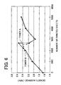
- Fig. 6 shows this measurement result.
- Fig. 6 is a graph showing the relation between the number of printed sheets and print density during endurance printing using the two toners A and B.
- Fig. 6 shows that during endurance printing with toner A and toner B, there is a large variation of print density from 2000 to 3000 printed sheets. In other words, there is a large variation of print duty during endurance printing.
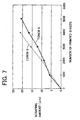
- Fig. 7 shows this measurement result.
- Fig. 7 is a graph showing the relation between the number of printed sheets and the scraping amount of the photoconductive layer for the two toners A and B. As shown in Fig. 7, there is a substantially linear variation according to the increase in the number of printed sheets for both toner A and toner B, and there is a large variation from 2000 to 3000 printed sheets.
- the toner components which affect the scraping amount of the photoconductive layer are iron oxide particles, Silica A and Silica B.
- Silica A, Silica B and iron oxide particles will be considered in that order.
- silica having a BET specific surface area of 100m 2 /g was used for Silica A.
- carbon black was used as a colorant
- a toner containing neither Silica A nor Silica B was prepared, and the scraping amount of the photoconductive layer was measured using this toner at a developing roller nip pressure of 290kPa. As a result of this measurement, it was found that this toner did not contribute to scraping of the photoconductive layer. This confirms that the carbon black used as colorant does not contribute to scraping of the photoconductive layer.
- a toner containing 1% (wt%) of Silica A was prepared, and the relation between the number of printed sheets and the scraping amount of the photoconductive layer was measured at a developing roller nip pressure of 290kPa.
- Fig. 8 shows this measurement result.
- Fig. 8 is a graph showing the relation between the number of printed sheets and the scraping amount of the photoconductive layer. The horizontal axis shows number of sheets, and the vertical axis shows the scraping amount.
- the scraping amount of the photoconductive layer after printing 6000 sheets was computed as 8.5 ⁇ m.
- the coefficient 1.4 is a coefficient obtained by converting the scraping amount of 8.5 ⁇ m per 6000 sheets, to 1000 sheets.
- silica having a BET specific surface area of 50m 2 /g was used.
- a toner containing carbon black as colorant and 1% (wt%) of Silica B was prepared, and the relation between the number of printed sheets and the scraping amount of the photoconductive layer was measured at a developing roller nip pressure of 290kPa.
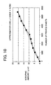
- Fig. 10 shows this measurement result.
- Fig. 10 is a graph showing the relation between the number of printed sheets and the scraping amount of the photoconductive layer. The horizontal axis shows the number of printed sheets, and the vertical axis shows the scraping amount.
- the scraping amount of the photoconductive layer after printing 6000 sheets was computed as 20.7 ⁇ m.
- Equation 4 the coefficient of 3.5 is a coefficient obtained by converting the scraping amount of 20.7 ⁇ m per 6000 sheets, to 1000 sheets.
- a toner was prepared containing 1% (wt%) of Silica A and 0.5% (wt%) of Silica B relative to polymer resin particles containing 6% (vol%) of iron oxide particles having various particle diameters, and the scraping amount of the photoconductive layer was measured after printing 1000 sheets using this toner at a developing roller nip pressure of 290kPa.
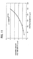
- Fig. 11 shows this measurement result.
- Fig. 11 is a graph showing the relation between the particle diameter of the iron oxide particles and the scraping amount of the photoconductive layer. The horizontal axis shows the particle diameter of the iron oxide particles, and the vertical axis shows the scraping amount.
- Equation 7 0.405e 4.62x ( ⁇ m)
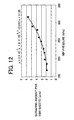
- a toner was prepared containing 0.5wt% of Silica A and 0.5wt% of Silica B relative to polymer resin toner particles containing iron oxide particles having a particle diameter of 0.3 ⁇ m, and the scraping amount of the photoconductive layer was measured after endurance printing of 1000 sheets using this toner while varying the developing roller nip pressure.
- Fig. 12 shows this measurement result.
- Fig. 12 is a graph showing the relation between the developing roller nip pressure and the scraping amount of the photoconductive layer. The horizontal axis shows the developing roller nip pressure, and the vertical axis shows the scraping amount.
- Equation 8 2 x 10 -7 x 3 + 9 x 10 -6 x 2 - 0.151x + 3.135
- Equation 5 and Equation 7 were both deduced for a developing roller nip pressure of 290kPa.
- the scraping amount is 4.4 ⁇ m. Therefore, in Equation 8, in order to determine the scraping amount of the photoconductive layer per 1kPa, Equation 8 may be divided by 4.4.
- Equation 10 gives the scraping amount per 1000 sheets, therefore if the number of printed sheets is s, the scraping amount per sheet is given by the following Equation 11. [Equation 11] (1.4x + 3.5y + 0.405e 4.62z ) x (2x10 -7 p 3 + 9 x 10 -6 p 2 - 0.151p + 3.135) / 4.4 x (s/1000) ( ⁇ m)
- the lower limit of the film thickness of the photoconductive layer required to form an image is 10 ⁇ m, so if the initial film thickness of the photoconductive layer is t, the film thickness of the photoconductive layer remaining after scraping due to printing is given by (t-10). If the remaining film thickness (t-10) is larger than the scraping amount given by Equation 11, there is no problem for image-forming. Expressing this in the form of an equation, the following Equation 12 is obtained.
- a toner was prepared varying the particle diameter of iron oxide particles (amount 6%, vol%) contained in the polymer resin particles, and the addition amounts of Silica A and Silica B, and the scraping amount of the photoconductive layer was measured by performing endurance printing of 10000 sheets using this toner while varying the developing roller nip pressure.
- the relation between the scraping amount and the function value (f) on the left-hand side of Equation 12 was examined.
- the endurance printing test was performed with 10000 sheets because endurance printing of 5000 sheets is not a permitted level for current products, and several tens of thousands is too far removed from the tolerance level for current products.
- the particle diameter of iron oxide was large, i.e., 0.6 ⁇ m
- the developing roller nip pressure was low, i.e., 50kPa
- the initial film thickness of the photoconductive layer was thick, i.e., 50 ⁇ m, so good results were obtained due to initial film thickness control.
- the particle diameter of iron oxide particles was 0.8 ⁇ m, which is too large, so good results were not obtained.
Landscapes
- Physics & Mathematics (AREA)
- General Physics & Mathematics (AREA)
- Developing Agents For Electrophotography (AREA)
Abstract
- the toner comprises iron oxide particles in resin particles; and
- the ratio (d/D) between the average particle diameter D of the toner and the average particle diameter d of the iron oxide particles is from 0.01 to 0.03.
Description
- This invention relates to an electrostatic developing toner used in an image-forming apparatus such as a printer, copier or facsimile machine which forms an image by developing an electrostatic latent image formed on a photoconductive layer of a photoconductive drum using a toner, i.e. by an electrophotographic method. In particular, it relates to an electrostatic developing toner which can effectively suppress fogging of the image by setting a ratio (d/D) between a toner average particle diameter D and an average particle diameter d of iron oxide particles contained in the toner which function as a colorant, or by setting a ratio (σr/σs) between a residual magnetization σr and a saturation magnetization σs of the iron oxide particles. It further relates to an electrostatic developing toner which can suppress the cracking amount of the photoconductive layer on the photoconductive drum accompanying the formation of the image even after about 10000 images have been formed.
- In the past, various image-forming apparatuses have been proposed featuring the formation of an image by an electrophotographic method using an electrostatic developing toner, wherein an additive such as silica particulates is added to toner particles containing a colorant to develop an electrostatic latent image formed on a photoconductive layer of a photoconductive drum.
- For example, JP Laid-open Patent Publication No. 05-341556 discloses a toner used in an image-forming apparatus wherein an electrostatic latent image is formed on a photoconductive layer of a latent image carrier via an optical source such as a laser, and toner is supplied to the electrostatic latent image from a toner carrier in contact with the latent image carrier to develop the electrostatic latent image. This toner is a one-component toner containing 20-50wt% of iron oxide in a binder resin containing a colorant such as carbon black.
- JP Laid-open Patent Publication No. 11-143121 discloses a toner used in an image-forming apparatus wherein an electrostatic latent image is formed on a photoconductive layer of an electrostatic latent image carrier, and the electrostatic latent image is developed by supplying toner from a developer carrier (developing roller). This toner contains a magnetic powder having a saturation magnetization σs of 5A.m2/kg or less, and a residual magnetization σr of 3A.m2/kg or less.
- When magnetic powders such as metal oxides are added to the toner for various purposes such as suppressing image fogging, it is necessary not only to consider the amount of magnetic powder added to the toner, but also the magnetic properties of these magnetic particles such as their saturation magnetization σs and residual magnetization σr.
- However, although JP Laid-open Patent Publication No. 05-341556 states that the iron oxide content of the toner is 20-50wt%, no mention is made of the other magnetic properties of the iron oxide.
- JP Laid-open Patent Publication No. 11-143121 discloses that the magnetic powder added to the toner has a saturation magnetization σs of 5A.m2/kg or less, and a residual magnetization σr of 3A.m2/kg or less, however as in the case of No. 05-341556, no mention is made of the other magnetic properties of the magnetic powder.
- JP Laid-open Patent Publication No. 11-194557 discloses an image-forming apparatus wherein a good image exposure is obtained according to a film pressure of an outermost layer of a photoconductive drum by inputting data relating to the photoconductive drum drive time and the time during which a voltage is applied to the charging roller, together with data relating to the contact pressure of a cleaning blade on a photoconductive drum from a non-volatile memory, calculating a film thickness of the outermost layer of the photoconductive drum based on this data in a control unit, and controlling the image exposure of an exposure apparatus on the photoconductive drum based on the calculated film thickness of the photoconductive drum.
- In the image-forming apparatus described in JP Laid-open Patent Publication No. 11-194557, two factors are considered whereby the photoconductive layer formed on the outer circumference of the photoconductive drum may be scraped when the image is formed. The first factor is that a contact charging method is used wherein a charging roller is brought into contact with the photoconductive drum to charge the outer circumferential surface of the photoconductive drum, and the photoconductive layer on the photoconductive drum may be scraped by the charging roller when the image is formed. The other factor is that a residual toner removal method is used wherein a cleaning blade is brought into pressure contact with the photoconductive layer surface on the photoconductive drum to remove residual toner on the photoconductive drum surface after transfer of the toner image to a transfer material, and the photoconductive layer on the photoconductive drum may be scraped by the cleaning blade.
- Hence, in the image-forming apparatus disclosed in JP Laid-open Patent Publication No. 11-194557, due to the design of the image-forming apparatus, the scraping of the photoconductive layer by the charging roller and the cleaning blade which are brought into contact with the circumferential surface of the photoconductive drum, are considered.
- Due to the design of the image-forming apparatus, if there are members which come into contact with the circumferential surface of the photoconductive layer of the photoconductive drum, the photoconductive layer will be scraped due to the frictional contact between these members and the photoconductive layer, but these are not the only possible factors responsible for the scraping of the photoconductive layer, and it is necessary to consider scraping of the photoconductive layer by various components of the electrostatic developing toner used in the image-forming apparatus.
- For example, if the colorant contained in the toner particles of the electrostatic latent image toner is a particulate pigment, its particle size and amount in the toner must be considered as possible factors in the scraping of the photoconductive layer, and if silica particulates are added to the toner particles, their particle size and addition amounts must also be considered.
- As a result of intensive studies undertaken by performing experiments on the iron oxide particles contained in toner and the effect of the magnetic properties of these iron oxide particles on image-forming, the inventors discovered that the relation between toner particle size and iron oxide particle size, and the relation between the saturation magnetization σs and residual magnetization σr of the iron oxide particles, had an important effect on the suppression of image fogging, and thereby arrived at the present invention. It is therefore an object of the present invention to provide an electrostatic developing toner which can effectively suppressing image fogging by setting the ratio (d/D) between the average particle diameter D of the toner and average particle diameter d of the iron oxide particles contained in the toner within a predetermined range, and setting the ratio (σr/σs) between the residual magnetization σr and saturation magnetization σs of the iron oxide particles to a predetermined value or less.
- The inventors also arrived at the present invention after intensive studies undertaken by performing experiments on the effect of components of electrostatic developing toners on the scraping of the photoconductive layer on the photoconductive drum. It is therefore a further object of this invention to provide an electrostatic developing toner which can suppress the scraping amount of the photoconductive layer on the photoconductive drum when an image is formed, to a constant value or less, even after about 10000 images are formed.
- The toner according to a first aspect of the invention is an electrostatic developing toner used in an image-forming apparatus wherein an electrostatic latent image is formed on a photoconductive layer formed on a circumferential surface of a photoconductive drum, and the electrostatic latent image is developed by supplying toner to the electrostatic latent image from a non-magnetic developing roller brought into contact with the photoconductive drum, wherein this electrostatic developing toner contains iron oxide particles in resin particles, and the ratio (d/D) between the average particle diameter D of the electrostatic developing toner and average particle diameter d of the iron oxide particles is within the
range 0. 01-0. 03. - In the electrostatic developing toner according to the first aspect of the invention, the ratio (d/D) between the average particle diameter D of the electrostatic developing toner and average particle diameter d of the iron oxide particles is set within the range 0.01-0.03, so image fogging is effectively suppressed. If the value of the aforesaid ratio (d/D) departs from this range, image fogging increases.
- The electrostatic developing toner according to a second aspect of the invention is an electrostatic developing toner used in an image-forming apparatus wherein an electrostatic latent image is formed on a photoconductive layer formed on a circumferential surface of a photoconductive drum, and the electrostatic latent image is developed by supplying toner to the electrostatic latent image from a non-magnetic developing roller brought into contact with the photoconductive drum, wherein this electrostatic developing toner contains iron oxide particles in resin particles, the iron oxide particles have a retentivity Hc of 3-7 kA/m in a magnetic field of 79. 6kA/m, and the ratio (σr/ σs) between their residual magnetization σr and saturation magnetization σs is 0.3 or less.
- In the electrostatic developing toner according to the second aspect of the invention, the iron oxide particles have a retentivity Hc of 3-7kA/m in a magnetic field of 79.6kA/m, and the ratio (σr/σs) of the residual magnetization σr and saturation magnetization σs in the iron oxide particles is 0.3 or less. Therefore, in a non-magnetic developing process which uses a non-magnetic developing roller, if the residual magnetization σr is small even if the saturation magnetization σs is high, the magnetic cohesive force between toner particles is weak and cohesion between toner particles can be prevented. Further, if the ratio (σr/σs) of the residual magnetization σr and saturation magnetization σs in the iron oxide particles is small, the electrostatic latent image can be developed without impairing toner fluid properties. As a result, image fogging can be effectively suppressed.
- The electrostatic developing toner according to a third aspect of the invention is an electrostatic developing toner used in an image-forming apparatus wherein an electrostatic latent image is formed on a photoconductive layer having a film thickness of 30-50µm formed on the circumferential surface of a photoconductive drum, and toner is supplied to the electrostatic latent image from a developing roller in contact.with the photoconductive drum at a nip pressure of 50-350kPa to develop the electrostatic latent image. This electrostatic developing toner contains a colorant in resin particles with the addition of at least one of a first silica particulate and a second silica particulate having mutually different particle diameters. The colorant is iron oxide having a particle diameter in the range 0.1-0.6µm, and its addition amount is 5-10vol% relative to toner. For the first silica particulate, the average value of the BET specific surface area is in the range 50-150m2/g, and its addition amount is 0.3-2wt%. For the second silica particulate, the average value of the BET specific surface area is in the range 20-100m2/g, and its addition amount is 0.5-2wt%.
- In the third aspect of the invention, in the image-forming apparatus wherein the initial film thickness of the photoconductive layer of the photoconductive drum is set to the range 30-50µm, the nip pressure of the developing roller on the photoconductive drum is set to the range 50-350kPa, and images are formed using the electrostatic developing toner prepared above, the scraping amount of the photoconductive layer of the photoconductive drum after about 10000 images have been formed, can be suppressed to 20-40µm or less. As a result, even after about 10000 images have been formed, the film thickness of the photoconductive layer can be maintained at 10µm or more, and images can be formed continuously.
- If the film thickness of the photoconductive layer is less than 10µm, image fogging increases as the film thickness decreases, and as a suitable image can then no longer be obtained, it is required that the photoconductive layer has a film thickness of 10µm or more in order to form a proper image.
- The above and further objects and novel features of the invention will more fully appear from the following detailed description of the same is read in connection with the accompanying drawings. It is to be expressly understood, however, that the drawings are for the purpose of illustration only and not intended as a definition of the limits of the invention.
-
- Fig. 1 is a perpendicular cross-sectional view of a laser printer;
- Fig. 2 is an enlarged lateral view of a developing unit and photoconductive drum of the laser printer;
- Fig. 3 is a graph showing a relation between the value of a ratio (d/D) and a fogging value;
- Fig. 4 is a graph showing a relation between the value of a ratio (σr/σs) and a fogging value;
- Fig. 5 is a graph showing a relation between a film thickness of a photoconductive layer and fogging;
- Fig. 6 is a graph showing a relation between a number of printed sheets and print density during endurance printing for two toners A and B;
- Fig. 7 is a graph showing a relation between the number of printed sheets and a scraping amount of the photoconductive layer during endurance printing for the two toners A and B;
- Fig. 8 is a graph showing a relation between the number of printed sheets and the scraping amount of the photoconductive layerp;
- Fig. 9 is a graph showing a linear plot of a relation between addition amounts of a Silica A and a Silica B, and the scraping amount of the photoconductive layer;
- Fig. 10 is a graph showing a relation between the number of printed sheets and the scraping amount of the photoconductive layer;
- Fig. 11 is a graph showing a relation between a particle diameter of iron oxide particles and the scraping amount of the photoconductive layer; and
- Fig. 12 is a graph showing a relation between a nip pressure of a developing roller and the scraping amount of the photoconductive layer.
- The electrostatic developing toner according to the present invention will now be described in more detail based on first and second embodiments.
- First, referring to Fig.1 and Fig.2, a laser printer which is an image-forming apparatus using the electrostatic developing toner for the first and second embodiments will be described. Fig. 1 is a perpendicular cross-sectional view of a laser printer, and Fig. 2 is an enlarged lateral view of the developing unit and photoconductive drum part of the laser printer.
- In Fig. 1, a
laser printer 1 comprises amain case 2, afeeder unit 10 for feeding a paper P which is a recording medium for forming an image, aphotoconductive drum 20 which is a photoconductive medium for performing the steps of charging to form an image, exposure, developing, transfer and recovery in sequence, a fixingunit 70 for fixing an image transferred from thephotoconductive drum 20 to the paper P on the paper P, and apaper eject tray 77 for ejecting the paper P on which the image is fixed along a paper transport path PP. - The
laser printer 1 comprises a drive means, not shown, for rotating thephotoconductive drum 20. Alaser scanner unit 30 for forming an electrostatic latent image on thephotoconductive drum 20 rotated by the drive means, a developingunit 50 comprising a developingroller 56 for developing the electrostatic latent image formed on thephotoconductive drum 20 by a toner, atransfer roller 60 for transferring the toner image developed on thephotoconductive drum 20 to the paper P, a discharge lamp 41 for discharging residual potential remaining on thephotoconductive drum 20 after transfer, a cleaningroller 42 for temporarily adsorbing residual toner and then discharging and leveling it on thephotoconductive drum 20 after charge has been eliminated by the discharge lamp 41, so that residual toner remaining on thephotoconductive drum 20 after transfer by thetransfer roller 60 is returned to the developingunit 50 at a predetermined timing using thephotoconductive drum 20, and acharger 40 for charging thephotoconductive drum 20 so that it can form an electrostatic latent image after discharging and leveling, are disposed in sequence around thephotoconductive drum 20. - The
feeder unit 10 further comprises apaper pressure plate 11 disposed inside thefeeder case 3 situated above the rear end of themain case 2 having substantially identical width dimensions to those of the paper P. Thepaper pressure plate 11 is supported free to oscillate at its rear end. Acompression spring 12 is provided at the front end of thepaper pressure plate 11, thepaper pressure plate 11 being pushed upwards elastically by thiscompression spring 12. Thepaper pressure plate 11 supports apaper feed roller 13 extending to the left and right such that it is free to rotate. Thepaper feed roller 13 is rotation driven with the paper feed timing by a drive system, not shown. Thefeeder unit 10 houses apaper feed cassette 14 set in thefeeder case 3 such that it can be freely inserted or removed obliquely, and which can accommodate plural sheets of the paper P cut to fixed dimensions. Due to the rotation of thepaper feed roller 13, the paper P in thepaper feed cassette 14 is supplied one sheet at a time from the uppermost sheet. Also, in order to prevent two sheets of the paper P from being transported together, thefeeder unit 10 comprises a separatingmember 15 below thepaper feed roller 13, this separatingmember 15 being pushed elastically against thepaper feed roller 13 by acompression spring 16. A pair of resistrollers paper feed roller 13. - In Fig. 1 and Fig. 2, the
photoconductive drum 20 comprises a positive charge material, for example an organic photoconductive material having a positive charge polycarbonate, as its main component. As shown in Fig. 2, thephotoconductive drum 20 is a hollow drum which is cylindrical, comprising aphotoconductive layer 22 of a predetermined thickness (e.g., the initial thickness is 30-15µm) comprising a photoconductive resin dispersed in polycarbonate on the outer circumference of an aluminumcylindrical sleeve 21, and is supported free to rotate in themain case 2 such that thecylindrical sleeve 21 is earthed. In other words, the electrostatic latent image which has positive polarity (positive charge) formed on thephotoconductive drum 20 is developed by developing the positive charge toner by the reverse developing method. Thephotoconductive drum 20 is rotation driven in the clockwise direction, viewed laterally, by a drive means. - In Fig. 1, the
laser scanner unit 30 is disposed below thephotoconductive drum 20, and comprises alaser imaging apparatus 31 which emits a laser L for forming an electrostatic latent image on thephotoconductive drum 20, a polygon mirror (5 facepiece mirror) 32 which is rotation driven, a pair oflenses 33, 34, and a pair of reflectingmirrors - The
charger 40 for example is a scorotron charger for positive charging which generates a corona discharge from a charging wire, for example of tungsten. In this aspect of the invention, a cleaneriess method is adopted wherein thecharger 40 is disposed facing thephotoconductive drum 20 but not in contact with it, so that residual toner on thephotoconductive drum 20 does not adhere to thecharger 40. - The discharge lamp 41 inside the
main case 2 for example comprises a light source such as a LED (light emitting diode), EL (electroluminescence) or a neon lamp, and the charge remaining on thephotoconductive drum 20 after transfer is removed (discharged) by irradiating with a light Le. - The cleaning
roller 42 varies a bias voltage so that, in a suction mode, theresidual toner 53 remaining on thephotoconductive drum 20 after transfer by thetransfer roller 60 is first aspirated, and in a discharge mode, the aspiratedresidual toner 53 is discharged and leveled over thephotoconductive drum 20 at a timing which does not interfere with the subsequent exposure, developing and transfer on thephotoconductive drum 20. By these actions, theresidual toner 53 is returned from thephotoconductive drum 20 to the developingunit 50. This cleaningroller 42 may for example be a foam elastic body having electrical conductivity comprising silicone rubber or urethane rubber which permits a bias voltage to be applied. - The cleaning
roller 42 is in contact with thephotoconductive drum 20, and as described above, as it comprises a foam elastic body such as silicone rubber or urethane rubber, friction with thephotoconductive drum 20 is reduced, and thephotoconductive layer 22 on thephotoconductive drum 20 is not scraped when cleaning is performed. - In Fig. 1 and Fig. 2, the developing
unit 50 comprises a doublecylindrical toner box 51 housed in adeveloper case 4 such that it can be freely inserted or removed. Thetoner box 51 houses anagitator 52 which is rotation driven, and thepositive charge toner 53 which has electrical insulating properties. At the front of thetoner box 51, atoner chamber 54 which accommodates thetoner 53 supplied due to the rotation of theagitator 52 via a toner suppliedport 51a formed in thetoner box 51, is formed. Thetoner chamber 54 houses asupply roller 55 disposed horizontally in its longitudinal direction, and which is supported free to rotate. The developingroller 56, which is also disposed horizontally in its longitudinal direction and supported free to rotate, partitions the front of thetoner chamber 54 and is in contact with thesupply roller 55 andphotoconductive drum 20. - The
supply roller 55 comprises a foam elastic body having electrical conductivity comprising silicone rubber or urethane rubber. The developingroller 56 forms a nip N due to contact with thephotoconductive drum 20 as shown in Fig. 2, and is also an electrically conducting rigid roller comprising silicone rubber or urethane rubber. Thelaser printer 1 of this aspect of the invention for example uses thephotoconductive drum 20 comprising an organic photoconductive material having positive charge toner and positive charge polycarbonate as its main components, and urethane rubber is the material of the developingroller 56. - As shown in Fig. 2, the
photoconductive drum 20 is rotated clockwise and the developingroller 56 is also rotated clockwise. A rotation direction of thephotoconductive drum 20 and that of the developingroller 56 are opposite to each other at the nip N. This means circumferential speed difference becomes large. As circumferential speed difference becomes larger, amount oftoner 53 the developingroller 56 can deliver to thephotoconductive drum 20 becomes larger. In other words, even if amount oftoner 53 carried onto the circumferential surface of the developingroller 56 is small, i.e., even if layer thickness oftoner 53 is thin, constant amount oftoner 53 can stably be delivered to thephotoconductive drum 20. This mechanism can make layer thickness oftoner 53 carried onto the developingroller 56 thin. Therefore,toner 53 can be charged uniformly and image quality can be improved. - The nip pressure (contact pressure) of the developing
roller 56 with thephotoconductive drum 20 is set within the range 50-350kPa. If this nip pressure falls below 50kPa, the offset of the developingroller 56 appears directly in the image, and gives rise to image distortion. Conversely, if the nip measure is more than 350kPa, the torque which drives the developingroller 56 is excessive, and interferes with the drive. - As shown in Fig. 2, the
toner chamber 54 is provided in thedeveloper case 4 in the developingunit 50, thistoner chamber 54 being formed such that there is a large upper gap S above thesupply roller 55. - In Fig. 1 and Fig. 2, a layer
thickness regulating blade 57 comprised of a thin stainless steel or copper plate with elasticity is installed facing downwards in thedeveloper case 4. - A
curved part 57a formed at the bottom of the layerthickness regulating blade 57 is in contact with the developingroller 56 such that it presses against it, and the layer thickness of thetoner 53 supplied from thesupply roller 55 and adhering as a layer to the surface of the developingroller 56, is regulated by this layerthickness regulating blade 57 to a predetermined thickness (approximately 7-12µm). - The
transfer roller 60, which is installed in contact with the upper side of thephotoconductive drum 20 and is supported free to rotate, comprises a foam elastic body having electrical conductivity comprising silicone rubber or urethane rubber. - The fixing
unit 70, which is installed downstream of thephotoconductive drum 20 in the transport direction, and comprises aheating roller 71 and pressure roller 72 housing a halogen lamp known in the art, fixes the toner image transferred to the underside of the paper P by heat and pressure so as to fix it on the paper P. - A pair of
transport rollers 75 for transporting the paper and thepaper eject tray 77 are respectively installed downstream of the fixingunit 70 in the transport direction. - Furthermore, as shown in Fig. 1, the
paper supply roller 13,photoconductive drum 20, fixingunit 70 and paper ejecttray 77 transport the paper P supplied from thepaper cassette 14 along the substantially linear paper transport path PP. - The toner according to present aspect of the invention is a positive charge toner, for example a non-magnetic one component toner comprising a polymer resin of styrene acrylate or the like, the proportion of iron oxide having substantially spherical particles which functions as a colorant in the polymer resin toner particles is 4-7vol% relative to toner, and various additives such as two types of silica particulates having different particle sizes to confer fluidity, and a wax and a charge controlling agent, are added.
- In addition to the aforesaid polymer toner, a powdered toner may also be used.
- Herein, as the iron oxide particles have a substantially spherical shape, the toner can be uniformly charged unlike the case where they have different shapes, and image fogging can be effectively suppressed. Also, as the iron oxide particles which act as a colorant account for 4-7vol% of the toner, image fogging is suppressed and the image can be formed with a suitable print density. If the iron oxide particle content is within the range 4-7vol%, the scraping amount of the photoconductive layer of the photoconductive drum due to the iron oxide particles in image-forming can be suppressed to within tolerance limits.
- Next, six types of iron oxide particles having different retentivity Hc, saturation magnetization σs, residual magnetization σr and average particle diameter d were manufactured, six types of toner containing these iron oxide particles were prepared (Examples 1-4, Comparative Examples 1, 2), and the fogging value in the initial stage of image-forming and the fogging value after printing 6000 sheets were measured for each toner.
- The retentivity Hc, saturation magnetization σs, residual magnetization σr and average particle diameter d of the iron oxide particles used in the toners of Examples 1-4, and Comparative Examples 1, 2, and the toner average particle diameter D measured for each toner, are listed in the following Table 1.
[Table 1] Toner Fogging Measured magnetic field 1kOe (=79.6kA/m) σs(Am2/ kg) σr/σs Particle diameter d Toner diameter D d/D Hc(oe) Hc(kA/m) σs(Am2/k 9) Example 1 0.35 59 4.70 66.7 5 0.07 0.22 9.155 0.024 1.01 59 4.70 66.7 5 0.07 0.22 9.155 0.024 Example 2 1.13 85 6.77 65 8.7 0.13 0.13 9.220 0.014 1.29 85 6.77 65 8.7 0.13 0.13 9.220 0.014 Example 3 0.56 93 7.40 66 9.3 0.14 0.19 8.907 0.021 1.03 93 7.40 66 9.3 0.14 0.19 8.907 0.021 Example 4 1.17 114 9.07 59.6 10 0.17 0.23 9.041 0.025 1.20 114 9.07 59.6 10 0.17 0.23 9.041 0.025 Comparative 2.39 283 22.5 0.6 0.2 0.33 0.3 8.832 0.034 Example 1 3.11 283 22.5 0.6 0.2 0.33 0.3 8.832 0.034 Comparative Example 2 5.06 58 4.62 0.2 0.1 0.50 0.017 9.240 0.002 - Table 1 shows the physical properties for the iron oxide particles used in the toner of Example 1.
- The retentivity Hc, measured at a measured magnetic field of 1kOe (97.6kA/m) was 4.70kA/m (59eO).
- The saturation magnetization σs was 66.7Am2/kg, and the residual magnetization σr was 5Am2/kg. Hence, the ratio (σr/σs) of the residual magnetization σr and saturation magnetization σs was 0.07.
- The average particle diameter d of iron oxide particles was 0.22µm. The average particle diameter D of the final toner was 9.155µm. Hence, the ratio (d/D) of the average particle diameter d of iron oxide particles to the average particle diameter D of toner was 0.024.
- For the aforesaid toners, the initial fogging value when images were first formed was 0. 35, and the fogging value after 6000 sheets had been printed was 1.01.
- In general, it is said that the fogging value must be 2.0 or less. Hence, the fogging value measured for the toner in Example 1 was within the permitted range for both the initial value and after printing 6000 sheets, and fogging was suppressed.
- Table 1 shows various physical properties for the iron oxide particles used in the toner of Example 2.
- The retentivity Hc measured at a measured magnetic field of 1kOe (97.6kA/m) was 6.77kA/m (85eO).
- The saturation magnetization σs was 65Am2/kg, and the residual magnetization σr was 8 . 7 Am2/kg. Hence, the ratio (σr/σs) of the residual magnetization σr and saturation magnetization σs was 0.13.
- The average particle diameter d of iron oxide particles was 0.13µm. The average particle diameter D of the final toner was 9.220µm. Hence, the ratio (d/D) of the average particle diameter d of iron oxide particles to the average particle diameter D of toner was 0.014.
- For the aforesaid toners, the initial fogging value when images were first formed was 1.13, and the fogging value after 6000 sheets had been printed was 1.29.
- In general, it is said that the fogging value must be 2.0 or less. Hence, the fogging value measured for the toner in Example 2 was within the permitted range for both the initial value and after printing 6000 sheets, and fogging was suppressed.
- Table 1 shows various physical properties of the iron oxide particles used in the toner of Example 3.
- The retentivity Hc measured at a measured magnetic field of 1kOe (97.6kA/m) was 7.40kA/m (93eO).
- The saturation magnetization σs was 66Am2/kg, and the residual magnetization σr was 9.3Am2/kg. Hence, the ratio (σr/σs) of the residual magnetization σr and saturation magnetization σs was 0.14.
- The average particle diameter d of iron oxide particles was 0.22µm. The average particle diameter D of the final toner was 8.907µm. Hence, the ratio (d/D) of the average particle diameter d of iron oxide particles to the average particle diameter D of toner was 0. 021.
- For the aforesaid toners, the initial fogging value when images were first formed was 0.56, and the fogging value after 6000 sheets had been printed was 1.03.
- In general, it is said that the fogging value must be 2.0 or less. Hence, the fogging value measured for the toner in Example 3 is within the permitted range for both the initial value and after printing 6000 sheets, and fogging is suppressed.
- Table 1 shows various physical properties of the iron oxide particles used in the toner of Example 4.
- The retentivity Hc measured at a measured magnetic field of 1kOe (97.6kA/m) was 9.07kA/m (114eO).
- The saturation magnetization σs was 59.6Am2/kg, and the residual magnetization σr was 10Am2/kg. Hence, the ratio (σr/σs) of the residual magnetization σr and saturation magnetization as was 0.17.
- The average particle diameter d of iron oxide particles was 0.23µm. The average particle diameter D of the final toner was 9.041µm. Hence, the ratio (d/D) of the average particle diameter d of iron oxide particles to the average particle diameter D of toner was 0.025.
- For the aforesaid toners, the initial fogging value when images were first formed was 1.17, and the fogging value after 6000 sheets had been printed was 1.20.
- In general, it is said that the fogging value must be 2.0 or less. Hence, the fogging value measured for the toner in Example 4 is within the permitted range for both the initial value and after printing 6000 sheets, and fogging is suppressed.
- Table 1 shows various physical properties of the iron oxide particles used in the toner of Comparative Example 1.
- The retentivity Hc measured at a measured magnetic field of 1kOe (97.6kA/m) was 22.5kA/m (283eO).
- The saturation magnetization σs was 0.6m2/kg, and the residual magnetization σr was 0.2Am2/kg. Hence, the ratio (σr/σs) of the residual magnetization σr and saturation magnetization σs was 0.33.
- The average particle diameter d of iron oxide particles was 0.3µm. The average particle diameter D of the final toner was 8.832µm. Hence, the ratio (d/D) of the average particle diameter d of iron oxide particles to the average particle diameter D of toner was 0.034.
- For the aforesaid toners, the initial fogging value when images were first formed was 2.39, and the fogging value after 6000 sheets had been printed was 3.11.
- In general, it is said that the fogging value must be 2.0 or less. Hence, the fogging value measured for the toner in Comparative Example 1 largely departs from the permitted range for both the initial value and after printing 6000 sheets, and fogging is not sufficiently suppressed.
- Table 1 shows various physical properties of the iron oxide particles used in the toner of Comparative Example 2.
- The retentivity Hc measured at a measured magnetic field of 1kOe (97.6kA/m) was 4.62kA/m (58eO).
- The saturation magnetization σs was 0.2Am2/kg, and the residual magnetization σr was 0.1Am2/kg. Hence, the ratio (σr/σs) of the residual magnetization σr and saturation magnetization σs was 0.5.
- The average particle diameter d of iron oxide particles was 0.017µm. The average particle diameter D of the final toner was 9.240µm. Hence, the ratio (d/D) of the average particle diameter d of iron oxide particles to the average particle diameter D of toner was 0.002.
- For the aforesaid toners, the initial fogging value when images were first formed was 5.06. This fogging value largely departs from the permitted range for the initial value (2.0), and image fogging is not completely suppressed even before printing 6000 sheets.
- To examine the relation between the ratio (d/D) of the iron oxide average particle diameter d and toner particle average particle diameter D, to the fogging value, the relation between the ratio (d/D) to the fogging value was plotted based on Table 1. Fig. 3 shows the results. Fig. 3 is a graph showing the relation of the ratio (d/D) to the fogging value. The horizontal axis shows the value of the ratio (d/D), and the vertical axis shows the fogging value.
- In Fig. 3, A, B, C, D are the plots obtained respectively for Example 1, Example 2, Example 3, Example 4, and E, F are the plots obtained respectively for Comparative Example 1 and Comparative Example 2.
- As the fogging value must be 2. 0 or less, in order to effectively suppress image fogging, as seen from Fig. 3, the value of the ratio (d/D) of the iron oxide average particle diameter d and toner particle average particle diameter D, must lie within the range 0.010-0.030. If the value of the ratio (d/D) is 0.030 or more, or 0.010 or less, the fogging value is 2.0 or more, and image fogging can no longer be effectively suppressed.
- To examine the relation between the ratio (σs/σr) of the saturation magnetization σs and the residual magnetization σr to the fogging value, the relation between the value of the ratio (σr/σs) and the fogging value was plotted. Fig. 4 shows the results. Fig. 4 is a graph showing the relation between the value of the ratio (σr/σs) and the fogging value. The horizontal axis shows the value of the ratio (σr/ σs), and the vertical axis shows the fogging value.
- In Fig. 4, A, B, C, D are the plots obtained respectively for Example 1, Example 2, Example 3, Example 4, and E, F are the plots obtained respectively for Comparative Example 1 and Comparative Example 2.
- As the fogging value must be 2.0 or less, in order to effectively suppress image fogging, as seen from Fig. 4, the value of the ratio (σr/σs) of the saturation magnetization σs and the residual magnetization σr, must be 0.03 or less. If the value of the ratio (σr/σs) is 0. 030 or more, the fogging value is 2. 0 or more, and image fogging can no longer be effectively suppressed.
- If the value of the ratio (σr/σs) is 0. 03 or less, in the non-magnetic developing process using a non-magnetic developing roller, if the residual magnetization σr is small even if the saturation magnetization σs is large, the magnetic cohesive force between toner particles is weak and cohesion of toner particles can be prevented, and if the ratio (σr/σs) of the residual magnetization σr and saturation magnetization σs is small, the electrostatic latent image can be developed without impairing toner fluid properties. As a result, image fogging can be effectively suppressed.
- On the other hand, if the residual magnetization σr is small and the saturation magnetization σs is also small (the ratio (σr/σs) of the two is large) , the magnetizing force of the iron oxide itself is weak, and as the charging of the toner overall is non-uniform, image fogging easily occurs.
- In the electrostatic developing toner of the first embodiment described above, the ratio (d/D) between the average particle diameter D of the toner and the average particle diameter d of the iron oxide particles contained in the toner which function as a colorant, is set to within the range 0.01-0.03, and the ratio (σr/σs) between the residual magnetization σr and saturation magnetization σs of the iron oxide particles is set to 0.3 or less. Hence, an electrostatic developing toner which effectively suppresses image fogging can be provided.
- An electrostatic developing toner according to a second embodiment will now be described. The image-forming apparatus according to this aspect, and its construction and function, do not differ from the image-forming apparatus according to the first aspect, so their description will not be repeated. Identical parts are also assigned identical numbers to those of the first aspect.
- The
toner 53 according to this aspect may for example be a non-magnetic one-component toner comprising a polymer resin of styrene acrylate or the like having a substantially spherical shape. The polymer resin toner particles contain iron oxide particles which function as a colorant, and various additives such as two types of silica particulates of mutually different particle diameters which impart fluidity (hereafter, the silica of small particle diameter will be referred to as Silica A, and the silica of large particle diameter will be referred to as Silica B), a wax and a charge controlling agent. Silica A acts mainly to improve toner fluidity, while toner B prevents adhesion between toner particles. Due to the combined effect of these two types of silica, image fogging and image dropout are prevented, and image quality is improved. In addition to the aforesaid polymer toner, the toner may also contain crushed toner. - Next, for the
toner 53 used in thelaser printer 1 wherein the initial film thickness of thelayer 22 formed on the circumferential surface of thephotoconductive drum 20 is set within the range 30-50µm, and the nip pressure of the developingroller 56 on thephotoconductive film 20 is on thephotoconductive drum 20 is set within the range 50-350kPa, function expressions were deduced between the particle size and content of iron oxide particles in the toner particles forming the toner, the addition amount and particle size of Silica A and Silica B, and the scraping amount of thephotoconductive layer 22. Next, the scraping amount of thephotoconductive layer 22 and the value of the function expressions when the particle size of the iron oxide particles and addition amounts of Silica A and Silica B were varied, were compared. - As is clear from the structure of the
laser printer 1, the cleaningroller 42, developingroller 56 andtransfer roller 60 are in contact with thephotoconductive layer 22 of thephotoconductive drum 20. As the cleaningroller 42 is made of a foam elastic material such as silicone rubber or urethane rubber, friction with thephotoconductive drum 20 is reduced, and thephotoconductive layer 22 of thephotoconductive drum 20 is not scraped when cleaning is performed. Further, as thetransfer roller 60 likewise comprises a foam elastic material having electrical conductivity such as silicone rubber or urethane rubber, thephotoconductive layer 22 of thephotoconductive drum 20 is not scraped when the image is transferred to the paper P. On the other hand, the developingroller 56 is a rigid roller made of urethane rubber, and whentoner 53 adhering to the surface of the developingroller 56, adheres to the electrostatic latent image on thephotoconductive layer 22 to develop it, thephotoconductive layer 22 is probably scraped depending on the nip pressure of the developingroller 56 which is brought into the nip part N. - Hence, the structural element of the
laser printer 1 leading to scraping of thephotoconductive layer 22 of thephotoconductive drum 20, will be assumed to be the developingroller 56. The scraping amount of thephotoconductive layer 22 varies according to a predetermined function having the nip pressure of the developingroller 56 on thisphotoconductive layer 22 as a parameter. - The toner comprises polymer resin toner particles containing iron oxide particles as colorant. These polymer resin toner particles contain the additives Silica A and Silica B, and other additives required for the toner composition such as a wax and a charge controlling agent.
- It will be assumed that the toner components which scrape the
photoconductive layer 22 on thephotoconductive drum 20 are the iron oxide particles, Silica A and Silica B which are harder than thephotoconductive layer 20, and that the scraping amount of thephotoconductive layer 22 varies according to a predetermined function having the particle diameter and content of the iron oxide particles, and the particle diameter and addition amounts of Silica A and Silica B, as parameters. - In order to determine the lower limit of the photoconductive layer required for image-forming, the relation between the film thickness of the photoconductive layer and image fogging was examined. Fig. 5 shows the results. Fig. 5 is a graph showing a relation between film thickness of the photoconductive layer and fogging, the horizontal axis showing the film thickness of the photoconductive layer and the vertical axis showing the fogging value.
- In Fig. 5, graph A shows the initial value for fogging obtained by measuring the fogging using a new photoconductive drum and toner. It is seen that the initial value of fogging is 8 which is within the measurement range, and has not changed.
- On the other hand, graph B shows the variation of the fogging value obtained using plural used photoconductive drums having photoconductive films of different film thickness and new toners. It is seen that when the film thickness of the photoconductive film is from 11µm to 10µm, the fogging value is 8 or less which is satisfactory, but if the film thickness is less than 10µm, the fogging increases beyond 8 as the film thickness decreases. This is thought to be due to the fact that when the film thickness of the photoconductive film decreases below 10µm, there is a drop in potential due to a decrease of insulating properties or charging capacity.
- From the above, it is seen that the lower limit of film thickness of the photoconductive film required to form an image must be 10µm.
- To examine the relation between print duty and scraping amount of the photoconductive film, the following measurements were performed.
- First, endurance printing was performed using two toners A and B (toners having an identical particle size but different colorants, the remaining components being identical), and the relation between number of printed sheets and print density was examined. Fig. 6 shows this measurement result. Fig. 6 is a graph showing the relation between the number of printed sheets and print density during endurance printing using the two toners A and B. As shown in Fig. 6, during endurance printing with toner A and toner B, there is a large variation of print density from 2000 to 3000 printed sheets. In other words, there is a large variation of print duty during endurance printing.
- Next, endurance printing was performed in the same way using the two toners A and B, and the relation between the number of printed sheets and scraping amount of the photoconductive layer was measured. Fig. 7 shows this measurement result. Fig. 7 is a graph showing the relation between the number of printed sheets and the scraping amount of the photoconductive layer for the two toners A and B. As shown in Fig. 7, there is a substantially linear variation according to the increase in the number of printed sheets for both toner A and toner B, and there is a large variation from 2000 to 3000 printed sheets.
- As is clear from a comparison of the graph of Fig. 4 and the graph of Fig. 7, there is no correlation between print duty and scraping amount of the photoconductive layer. Therefore, print duty will not be considered in deducing the functional relations below concerning scraping amount of the photoconductive layer.
- (i) As discussed in the above, the toner components which affect the scraping amount of the photoconductive layer are iron oxide particles, Silica A and Silica B. First, it will be considered how these components affect the scraping of the photoconductive layer. In the following, Silica A, Silica B and iron oxide particles will be considered in that order.
- For Silica A, silica having a BET specific surface area of 100m2/g was used. To examine the effect of this Silica A on the scraping of the photoconductive layer, carbon black was used as a colorant, a toner containing neither Silica A nor Silica B was prepared, and the scraping amount of the photoconductive layer was measured using this toner at a developing roller nip pressure of 290kPa. As a result of this measurement, it was found that this toner did not contribute to scraping of the photoconductive layer. This confirms that the carbon black used as colorant does not contribute to scraping of the photoconductive layer.
- Next, using carbon black as colorant, a toner containing 1% (wt%) of Silica A was prepared, and the relation between the number of printed sheets and the scraping amount of the photoconductive layer was measured at a developing roller nip pressure of 290kPa. Fig. 8 shows this measurement result. Fig. 8 is a graph showing the relation between the number of printed sheets and the scraping amount of the photoconductive layer. The horizontal axis shows number of sheets, and the vertical axis shows the scraping amount.
- In Fig. 8, the scraping amount of the photoconductive layer tends to increase linearly with increase in the number of printed sheets. If an approximation relation is fitted to the measurement points on the graph, the following
Equation 1 is obtained.
- Based on
Equation 1, the scraping amount of the photoconductive layer after printing 6000 sheets was computed as 8.5µm. - Here, it was found that when Silica A and Silica B are not added (
addition amount 0%), there is no scraping of the photoconductive layer, therefore concerning the equation representing the scraping amount of the photoconductive layer, there is no problem in assuming the linear plot passing through the origin shown in graph C of Fig. 9. - In practice, when the addition amounts of Silica A and Silica B are 0%, filming occurs so the intercept on graph C of Fig. 9 may be considered to be slightly negative, but herein, it will be assumed that a more stringent condition (intercept = 0µm) is used.
- Hence, in the graph C of Fig. 9, if x% of Silica A is added, the scraping amount of the photoconductive layer after printing 1000 sheets is given by the following
Equation 2.
- In
Equation 2, the coefficient 1.4 is a coefficient obtained by converting the scraping amount of 8.5µm per 6000 sheets, to 1000 sheets. - For Silica B, silica having a BET specific surface area of 50m2/g was used. To examine the effect of Silica B on the scraping amount of the photoconductive layer, a toner containing carbon black as colorant and 1% (wt%) of Silica B was prepared, and the relation between the number of printed sheets and the scraping amount of the photoconductive layer was measured at a developing roller nip pressure of 290kPa. Fig. 10 shows this measurement result. Fig. 10 is a graph showing the relation between the number of printed sheets and the scraping amount of the photoconductive layer. The horizontal axis shows the number of printed sheets, and the vertical axis shows the scraping amount.
- In Fig. 10, the scraping amount of the photoconductive layer tends to increase linearly with increase in the number of printed sheets. If an approximation relation is fitted to the measurement points on the graph, the following
Equation 3 is obtained.
- Based on
Equation 3, the scraping amount of the photoconductive layer after printing 6000 sheets was computed as 20.7µm. - Herein, as in the case of Silica A, it was confirmed that when Silica A and Silica B are not added (
addition amount 0%), there is no scraping of the photoconductive layer, therefore concerning the equation representing the scraping amount of the photoconductive layer, there is no problem in assuming a linear plot passing through the origin shown in graph D of Fig. 9. - In practice, when the addition amounts of Silica A and Silica B are 0%, filming occurs so the intercept on graph D of Fig. 9 may be considered to be slightly negative, but herein, it will be assumed that a more stringent condition (intercept = 0µm) is used.
- Hence, in graph D of Fig. 9, if y% of Silica B is added, the scraping amount of the photoconductive layer after printing 1000 sheets is given by the following
Equation 4.
- In
Equation 4, the coefficient of 3.5 is a coefficient obtained by converting the scraping amount of 20.7µm per 6000 sheets, to 1000 sheets. - From the above, when x% of Silica A and y% of Silica B were added and the developing roller nip pressure was set to 290kPa, the contribution of Silica A and Silica B to the scraping amount of the photoconductive layer after printing 1000 sheets, is given by the following
Equation 5.
- To examine the effect of iron oxide particles on the scraping amount of the photoconductive layer, a toner was prepared containing 1% (wt%) of Silica A and 0.5% (wt%) of Silica B relative to polymer resin particles containing 6% (vol%) of iron oxide particles having various particle diameters, and the scraping amount of the photoconductive layer was measured after printing 1000 sheets using this toner at a developing roller nip pressure of 290kPa. Fig. 11 shows this measurement result. Fig. 11 is a graph showing the relation between the particle diameter of the iron oxide particles and the scraping amount of the photoconductive layer. The horizontal axis shows the particle diameter of the iron oxide particles, and the vertical axis shows the scraping amount.
- In Fig. 11, the scraping amount of the photoconductive layer tends to increase exponentially with increase in the particle diameter of the iron oxide particles. If an approximation relation is fitted to the measurement points on the graph, the following
Equation 6 is obtained.
- Herein, based on
Equation 6, if the particle diameter of the iron oxide particles is z (µm), the effect of the iron oxide particles on the scraping amount of the photoconductive layer after printing 1000 sheets is given by the followingEquation 7.
- To examine the effect of the scraping amount of the photoconductive layer based on the nip pressure of the developing roller on the photoconductive drum, a toner was prepared containing 0.5wt% of Silica A and 0.5wt% of Silica B relative to polymer resin toner particles containing iron oxide particles having a particle diameter of 0.3µm, and the scraping amount of the photoconductive layer was measured after endurance printing of 1000 sheets using this toner while varying the developing roller nip pressure. Fig. 12 shows this measurement result. Fig. 12 is a graph showing the relation between the developing roller nip pressure and the scraping amount of the photoconductive layer. The horizontal axis shows the developing roller nip pressure, and the vertical axis shows the scraping amount.
- In Fig. 12, the scraping amount of the photoconductive layer increases along a curve with increase of the developing roller nip pressure. If an approximation relation is fitted to the measurement points on the graph, the following
Equation 8 is obtained.
- Herein,
Equation 5 andEquation 7 were both deduced for a developing roller nip pressure of 290kPa. Calculating the scraping amount of the photoconductive layer for this nip pressure of 290kPa fromEquation 8, the scraping amount is 4.4µm. Therefore, inEquation 8, in order to determine the scraping amount of the photoconductive layer per 1kPa,Equation 8 may be divided by 4.4. - In other words, the scraping amount of the photoconductive layer corresponding to a developing roller nip pressure of 1kPa(p) after printing 1000 sheets is represented by the following
Equation 9.
- (vi) Based on the above description, using a toner containing x% (wt%) of Silica A and y% (wt%) of Silica B in polymer resin toner particles containing 6% (vol%) of iron oxide having a particle diameter of z µm, if 1000 sheets are printed at a developing roller nip pressure p (kPa), the scraping amount is given by the following
Equation 10.
-
Equation 10 gives the scraping amount per 1000 sheets, therefore if the number of printed sheets is s, the scraping amount per sheet is given by the followingEquation 11.
- Herein, as described above, the lower limit of the film thickness of the photoconductive layer required to form an image is 10µm, so if the initial film thickness of the photoconductive layer is t, the film thickness of the photoconductive layer remaining after scraping due to printing is given by (t-10). If the remaining film thickness (t-10) is larger than the scraping amount given by
Equation 11, there is no problem for image-forming. Expressing this in the form of an equation, the followingEquation 12 is obtained.
- (1) A toner was prepared varying the particle diameter of iron oxide particles (
amount 6%, vol%) contained in the polymer resin particles, and the addition amounts of Silica A and Silica B, and the scraping amount of the photoconductive layer was measured by performing endurance printing of 10000 sheets using this toner while varying the developing roller nip pressure. The relation between the scraping amount and the function value (f) on the left-hand side ofEquation 12 was examined. - Herein, the endurance printing test was performed with 10000 sheets because endurance printing of 5000 sheets is not a permitted level for current products, and several tens of thousands is too far removed from the tolerance level for current products.
-
- (i) A toner was prepared varying the particle diameter of iron oxide particles (
amount 6%, vol%) contained in the polymer resin particles, and the addition amounts of Silica A and Silica B, and endurance printing of 10000 sheets was performed using this toner while varying the developing roller nip pressure. The results are shown as Examples 1-6 in the following Table 2.
- (ii) In Example 1, a toner was used wherein the addition amount of Silica A was 0.5%, the addition amount of Silica B was 0.5% and the particle diameter of the iron oxide contained in the polymer resin particles was 0.3µm, and the developing roller nip pressure was 200kPa. The initial film thickness of the photoconductive layer was 32.7µm, and the film thickness after printing 10000 sheets was 14.5µm. Due to this, the scraping amount of the photoconductive layer was 18.2µm. The function value f was -3.5, and the conditions of
Equation 12 were satisfied.
In this case, based on the fact that the addition amounts of Silica A and Silica B, the particle diameter of iron oxide and the developing roller nip pressure are within satisfactory ranges, good results were obtained. - (iii) In Example 2, a toner containing 0.4% of Silica A but no Silica B, wherein the particle diameter of iron oxide contained in the polymer resin particles was 0.1µm, was used, and the developing roller nip pressure was set to 350kPa. The initial film thickness of the photoconductive layer was 32.3µm, and the film thickness after printing 10000 sheets was 11.5µm. Due to this, the scraping amount of the photoconductive layer was 20.8µm. The function value f was -1.7, and the conditions of
Equation 12 were satisfied.
In this case, the developing roller nip pressure was set high to 350kPa, but as the BET specific surface area of Silica A was 100m2/g, its particle diameter was small and the particle diameter of iron oxide was small, i.e., 0.1µm, good results were obtained. - (iv) In Example 3, a toner containing 0.3% of Silica A but no Silica B, wherein the particle diameter of iron oxide contained in the polymer resin particles was 0.45µm, was used, and the developing roller nip pressure was set to 50kPa. The initial film thickness of the photoconductive layer was 31.8µm, and the film thickness after printing 10000 sheets was 11.9µm. Due to this, the scraping amount of the photoconductive layer was 19.9µm. The function value f was -1.6, and the conditions of
Equation 12 were satisfied.
In this case, the particle diameter of iron oxide particles was large, i.e., 0.45µm, but as the developing roller nip pressure was low, i.e., 50kPa, good results were obtained. - (v) In Example 4, a toner containing no Silica A and 1.8% Silica B, wherein the particle diameter of iron oxide contained in the polymer resin particles was 0.1µm, was used, and the developing roller nip pressure was set to 50kPa. The initial film thickness of the photoconductive layer was 49.5µm, and the film thickness after printing 10000 sheets was 11.3µm. Due to this, the scraping amount of the photoconductive layer was 38.2µm. The function value f was -1.2, and the conditions of
Equation 12 were satisfied.
In this case, the addition amount of Silica B was high, i.e., 1.8%, but as the developing roller nip pressure was low, i.e., 50kPa, the particle diameter of iron oxide was small, i.e., 0.1µm and the initial film thickness of the photoconductive layer was thick, i.e., 49.5µm, good results were obtained due to initial film thickness control. - (vi) In Example 5, a toner containing 2% of Silica A and 1% of Silica B, wherein the particle diameter of iron oxide contained in the polymer resin particles was 0.1µm, was used, and the developing roller nip pressure was set to 50kPa. The initial film thickness of the photoconductive layer was 50µm, and the film thickness after printing 10000 sheets was 11.1µm. Due to this, the scraping amount of the photoconductive layer was 38.9µm. The function value f was -1.7, and the conditions of
Equation 12 were satisfied.
In this case, the addition amount of Silica A was 2% and the addition amount of Silica B was 1% so the overall addition amount was large, the developing roller nip pressure was low, i.e, 50kPa, the particle diameter of iron oxide was small, i.e., 0.1µm and the initial film thickness of the photoconductive layer was thick, i.e, 50µm, so good results were obtained due to initial film thickness control. - (vii) In Example 6, a toner containing 0.5% of Silica A but no Silica B, wherein the particle diameter of iron oxide contained in the polymer resin particles was 0.6µm, was used, and the developing roller nip pressure was set to 50kPa. The initial film thickness of the photoconductive layer was 50µm, and the film thickness after printing 10000 sheets was 10.8µm. Due to this, the scraping amount of the photoconductive layer was 39.2µm. The function value f was -0. 4, and the conditions of
Equation 12 were satisfied. - In this case, the particle diameter of iron oxide was large, i.e., 0.6µm, the developing roller nip pressure was low, i.e., 50kPa and the initial film thickness of the photoconductive layer was thick, i.e., 50µm, so good results were obtained due to initial film thickness control.
-
- (i) A toner was prepared varying the particle diameter of iron oxide particles (
amount 6%, vol%) contained in the polymer resin particles, and the addition amounts of Silica A and Silica B, and endurance printing of 10000 sheets was performed using this toner while varying the developing roller nip pressure. The results are shown as Comparative Examples 1-5 in the Table 2. - (ii) In Comparative Example 1, a toner containing 0.3% of Silica A but no Silica B, wherein the particle diameter of iron oxide contained in the polymer resin particles was 0.1µm, was used, and the developing roller nip pressure was set to 400kPa. The initial film thickness of the photoconductive layer was 31.2µm, and the film thickness after printing 10000 sheets was 3.6µm. Due to this, the scraping amount of the photoconductive layer was 27.6µm. The function value f was 31.2, and the conditions of
Equation 12 were not satisfied.
In this case, the developing roller nip pressure was too high, so good results were not obtained. - (iii) In Comparative Example 2, a toner containing 0.6% of Silica A but no Silica B, wherein the particle diameter of iron oxide contained in the polymer resin particles was 0.1µm, was used, and the developing roller nip pressure was set to 50kPa. The initial film thickness of the photoconductive layer was 48.7µm, and the film thickness after printing 10000 sheets was 0µm. The function value f was 11.2, and the conditions of
Equation 12 were not satisfied.
In this case, the addition amount of Silica A was too high, so good results were not obtained. - (iv) In Comparative Example 3, a toner containing no Silica A and 3% Silica B, wherein the particle diameter of iron oxide contained in the polymer resin particles was 0.1µm, was used, and the developing roller nip pressure was set to 50kPa. The initial film thickness of the photoconductive layer was 48.5µm, but the film thickness of the photoconductive layer during endurance printing of 10000 sheets was 0µm, so printing stopped midway during the operation. The function value f was 23.0, and the conditions of
Equation 12 were not satisfied.
In this case, the addition amount of Silica B, which had a large particle diameter (BET specific surface area 50m2/g), was too large, so good results were not obtained. - (v) In Comparative Example 4, a toner containing 3% of Silica A and 1% of Silica B, wherein the particle diameter of iron oxide contained in the polymer resin particles was 0.1µm, was used, and the developing roller nip pressure was set to 50kPa. The initial film thickness of the photoconductive layer was 48.7µm, but the film thickness of the photoconductive layer during endurance printing of 10000 sheets was 0µm, so printing stopped midway during the operation. The function value f was 11.2, and the conditions of
Equation 12 were not satisfied.
In this case, the addition amount of Silica A was large, and 1% of Silica B which had a large particle diameter was also added, so the total addition amount of silicas A and B was too large, and good results were not obtained. - (vi) In Comparative Example 5, a toner containing 0.5% of Silica A but no Silica B, wherein the particle diameter of iron oxide contained in the polymer resin particles was 0.8µm, was used, and the developing roller nip pressure was set to 50kPa. The initial film thickness of the photoconductive layer was 49.5µm, but the film thickness of the photoconductive layer during endurance printing of 10000 sheets was 0µm, so printing stopped midway during the operation. The function value f was 54.4, and the conditions of
Equation 12 were not satisfied. - In this case, the particle diameter of iron oxide particles was 0.8µm, which is too large, so good results were not obtained.
- As described above, according to the electrostatic developing toner of the second embodiment, even when images are formed after printing about 10000 sheets, scraping of the photoconductive layer on the photoconductive drum due to image-forming can be suppressed to below a fixed amount.
Claims (10)
- An electrostatic developing toner for use in an image-forming apparatus in which an electrostatic latent image is formed on a photoconductive film on the circumferential surface of a photoconductive drum, and toner is supplied to the electrostatic latent image from a non-magnetic developing roller, which is in contact with the photoconductive drum, to develop the electrostatic latent image, characterised in that:the toner comprises iron oxide particles in resin particles; andthe ratio (d/D) between the average particle diameter D of the toner and the average particle diameter d of the iron oxide particles is from 0.01 to 0.03.
- A toner according to claim 1, wherein the retentivity Hc of the iron oxide particles is from 3 to 7 kA/m in a magnetic field of 79.6 kA/m, and the ratio (σr/σs) of the residual magnetization σr to the saturation magnetization σs is 0.3 or less.
- An electrostatic developing toner for use in an image-forming apparatus in which an electrostatic latent image is formed on a photoconductive film on the circumferential surface of a photoconductive drum, and toner is supplied to the electrostatic latent image from a non-magnetic developing roller, which is in contact with the photoconductive drum, to develop the electrostatic latent image, characterised in that:the toner comprises iron oxide particles in resin particles;the iron oxide particles have a retentivity of from 3 to 7 kA/m in a magnetic field of 79.6 kA/m; andthe ratio (σr/σs) of the residual magnetization σr to the saturation magnetization σs is 0.3 or less.
- A toner according to any one of claims 1 to 3, wherein the iron oxide particles have a spherical shape.
- A toner according to any one of claims 1 to 4, wherein the amount of iron oxide particles relative to the toner is 4 to 7 vol %.
- An electrostatic developing toner for use in an image-forming apparatus in which an electrostatic latent image is formed on a photoconductive film, which has a film thickness of from 30 to 50 µm, on the circumferential surface of a photoconductive drum, and toner is supplied to the electrostatic latent image from a developing roller, which is in contact with the photoconductive drum, at a nip pressure of from 50 to 350 kPa to develop the electrostatic latent image, wherein the toner comprises an iron oxide colorant in resin particles and contains at least one of a first silica particulate and a second silica particulate, wherein:(i) from 5 to 10 vol% relative to the toner of iron oxide with a particle diameter from 0.1 to 6µm;(ii) from 0.3 to 2 wt% relative to the toner of a first silica particulate with an average BET specific surface area from 50 to 150 m2/g;(iii) 0.5 to 2 wt% relative to the toner of a second silica particulate with an average BET specific surface area from 20 to 100 m2/g,wherein the two silica particulates have different average particle diameters.
- A toner according to claim 6, wherein the amount of the iron oxide relative to the toner is 6 to 8 vol%.
- A toner according to either claim 6 or claim 7, wherein the average BET specific surface area of the first silica particulate is from 80 to 120 m2/g.
- A toner according to any one of claims 6 to 8, wherein the average BET specific surface area of the second silica particulate is from 40 to 80 m2/g.
- An image formed from an electrostatic latent image which image comprises a toner according to any one of claims 1 to 9.
Applications Claiming Priority (4)
| Application Number | Priority Date | Filing Date | Title |
|---|---|---|---|
| JP2002276739 | 2002-09-24 | ||
| JP2002276739A JP2004117457A (en) | 2002-09-24 | 2002-09-24 | Electrostatic development toner |
| JP2002282306 | 2002-09-27 | ||
| JP2002282306A JP3918703B2 (en) | 2002-09-27 | 2002-09-27 | Electrostatic development toner |
Publications (3)
| Publication Number | Publication Date |
|---|---|
| EP1403726A2 true EP1403726A2 (en) | 2004-03-31 |
| EP1403726A3 EP1403726A3 (en) | 2004-07-28 |
| EP1403726B1 EP1403726B1 (en) | 2006-11-15 |
Family
ID=31980617
Family Applications (1)
| Application Number | Title | Priority Date | Filing Date |
|---|---|---|---|
| EP03256017A Expired - Lifetime EP1403726B1 (en) | 2002-09-24 | 2003-09-24 | Electrostatic developing toner |
Country Status (5)
| Country | Link |
|---|---|
| US (2) | US20040081904A1 (en) |
| EP (1) | EP1403726B1 (en) |
| CN (1) | CN100373265C (en) |
| AT (1) | ATE345518T1 (en) |
| DE (1) | DE60309644T2 (en) |
Family Cites Families (43)
| Publication number | Priority date | Publication date | Assignee | Title |
|---|---|---|---|---|
| DE2830012C2 (en) * | 1977-07-07 | 1983-07-28 | Ricoh Co., Ltd., Tokyo | Device for developing an electrostatic charge image |
| JPS58189646A (en) * | 1982-04-01 | 1983-11-05 | Canon Inc | magnetic toner |
| JPH0810341B2 (en) * | 1986-05-28 | 1996-01-31 | キヤノン株式会社 | Magnetic toner |
| JPH0812444B2 (en) | 1987-10-30 | 1996-02-07 | 株式会社東芝 | Electrostatic image developing method and apparatus |
| JPH07120071B2 (en) * | 1988-02-29 | 1995-12-20 | キヤノン株式会社 | Magnetic toner |
| EP0423743B1 (en) * | 1989-10-17 | 1995-03-01 | Canon Kabushiki Kaisha | Magnetic toner |
| JPH0782245B2 (en) | 1989-10-17 | 1995-09-06 | キヤノン株式会社 | Magnetic toner |
| CA2039290C (en) * | 1990-03-29 | 1994-10-11 | Masaaki Taya | Magnetic toner |
| EP0468525B1 (en) * | 1990-07-27 | 1997-11-26 | Canon Kabushiki Kaisha | Magnetic developer, electrophotographic apparatus and recognition method of magnetic ink character |
| JPH05341556A (en) | 1992-06-05 | 1993-12-24 | Seiko Epson Corp | One-component toner and nonmagnetic developing method using the same |
| JP3333978B2 (en) | 1994-03-02 | 2002-10-15 | コニカ株式会社 | One-component magnetic developer and developing method |
| JPH07261446A (en) | 1994-03-17 | 1995-10-13 | Sharp Corp | Toner for electrostatic charge development |
| JP3079148B2 (en) | 1994-08-29 | 2000-08-21 | 京セラミタ株式会社 | Recycling development method using single layer type organic photoreceptor |
| JPH08240925A (en) | 1994-11-08 | 1996-09-17 | Canon Inc | Toner for developing electrostatic latent image, image forming method and image forming apparatus |
| KR100211268B1 (en) | 1994-11-08 | 1999-07-15 | 미따라이 하지메 | Image Forming Method and Image Forming Apparatus |
| JPH08278658A (en) * | 1995-02-08 | 1996-10-22 | Ricoh Co Ltd | Toner for electrostatic image development |
| US5774771A (en) | 1995-02-10 | 1998-06-30 | Canon Kabushiki Kaisha | Image forming method and apparatus using a particular toner |
| JP3243597B2 (en) | 1995-02-10 | 2002-01-07 | キヤノン株式会社 | Image forming method, image forming apparatus, and toner kit |
| JP3467966B2 (en) | 1996-05-21 | 2003-11-17 | 三菱化学株式会社 | One-component developer and image forming method using the same |
| JP3643445B2 (en) | 1996-07-22 | 2005-04-27 | 株式会社巴川製紙所 | Non-magnetic one-component toner |
| JPH1049024A (en) | 1996-07-31 | 1998-02-20 | Kyocera Corp | Image forming device |
| JPH1152705A (en) | 1997-07-31 | 1999-02-26 | Brother Ind Ltd | Image forming device |
| US6141519A (en) | 1996-12-05 | 2000-10-31 | Brother Kogyo Kabushiki Kaisha | Image-forming apparatus having at least one of additives in the non-magnetic single-component toner exhibiting electrical conductivity |
| US6128458A (en) | 1996-12-05 | 2000-10-03 | Brother Kogyo Kabushiki Kaisha | Image forming device with toner charge increasing structure |
| JPH10239896A (en) | 1997-02-28 | 1998-09-11 | Brother Ind Ltd | Developing device and image forming device |
| JPH117197A (en) | 1997-06-16 | 1999-01-12 | Hitachi Metals Ltd | Image forming method and negatively charged non-magnetic toner |
| JPH11102089A (en) | 1997-07-31 | 1999-04-13 | Kyocera Corp | Image forming method using electrophotographic method |
| DE69812245T2 (en) | 1997-07-31 | 2004-02-12 | Kyocera Corp. | Electrophotographic imaging process |
| JPH11143121A (en) * | 1997-11-07 | 1999-05-28 | Fuji Xerox Co Ltd | Developer and image forming method using that |
| JPH11194557A (en) | 1997-12-26 | 1999-07-21 | Canon Inc | Image forming device |
| JP3543616B2 (en) | 1998-05-13 | 2004-07-14 | ブラザー工業株式会社 | Image forming device |
| JP2000184220A (en) | 1998-12-16 | 2000-06-30 | Ricoh Co Ltd | Calibration method |
| JP2000258984A (en) | 1999-03-09 | 2000-09-22 | Brother Ind Ltd | Image forming apparatus and developing apparatus |
| US6337956B1 (en) | 1999-02-24 | 2002-01-08 | Brother Kogyo Kabushiki Kaisha | Developing device having toner agitation member and cleaning member cleaning light transmission window |
| JP2001109188A (en) * | 1999-10-04 | 2001-04-20 | Ricoh Co Ltd | Electrostatic toner |
| JP2000131928A (en) | 1999-12-02 | 2000-05-12 | Seiko Epson Corp | Image forming method |
| JP2001166589A (en) | 1999-12-13 | 2001-06-22 | Ricoh Co Ltd | Image forming device |
| JP3532480B2 (en) | 1999-12-21 | 2004-05-31 | シャープ株式会社 | Developing device and manufacturing method thereof |
| JP2001337482A (en) | 2000-03-23 | 2001-12-07 | Brother Ind Ltd | Color image forming equipment |
| EP1168087A1 (en) * | 2000-06-26 | 2002-01-02 | Toda Kogyo Corporation | Magnetic composite particles for black magnetic toner and black magnetic toner using the same |
| US6630275B2 (en) * | 2001-03-15 | 2003-10-07 | Canon Kabushiki Kaisha | Magnetic toner and process cartridge |
| JP2003262972A (en) * | 2002-03-07 | 2003-09-19 | Canon Inc | Image forming device |
| JP3918703B2 (en) * | 2002-09-27 | 2007-05-23 | ブラザー工業株式会社 | Electrostatic development toner |
-
2003
- 2003-09-22 US US10/665,421 patent/US20040081904A1/en not_active Abandoned
- 2003-09-24 EP EP03256017A patent/EP1403726B1/en not_active Expired - Lifetime
- 2003-09-24 AT AT03256017T patent/ATE345518T1/en not_active IP Right Cessation
- 2003-09-24 CN CNB031603521A patent/CN100373265C/en not_active Expired - Fee Related
- 2003-09-24 DE DE60309644T patent/DE60309644T2/en not_active Expired - Lifetime
-
2006
- 2006-01-03 US US11/322,229 patent/US7280786B2/en not_active Expired - Lifetime
Also Published As
| Publication number | Publication date |
|---|---|
| US20040081904A1 (en) | 2004-04-29 |
| US20060104669A1 (en) | 2006-05-18 |
| EP1403726A3 (en) | 2004-07-28 |
| CN100373265C (en) | 2008-03-05 |
| US7280786B2 (en) | 2007-10-09 |
| CN1495551A (en) | 2004-05-12 |
| DE60309644T2 (en) | 2007-09-06 |
| DE60309644D1 (en) | 2006-12-28 |
| ATE345518T1 (en) | 2006-12-15 |
| EP1403726B1 (en) | 2006-11-15 |
Similar Documents
| Publication | Publication Date | Title |
|---|---|---|
| KR100338202B1 (en) | Toner and Image Forming Method | |
| US6175703B1 (en) | Image forming apparatus and process cartridge | |
| EP1513026B1 (en) | Developer carrying member and developing method by using thereof | |
| US5095341A (en) | Image forming apparatus using one component developing agent with roller applicator | |
| US7233758B2 (en) | Developing apparatus featuring a developer carrying member with an elastic surface layer | |
| US7103305B2 (en) | Developing apparatus for image forming apparatus | |
| US5805966A (en) | Developer layer forming device having a blade pressed against a developing roller at an edge portion | |
| EP1357438A2 (en) | Charging system, process cartridge and image forming apparatus | |
| EP0939349B1 (en) | Developing apparatus using one-component toner | |
| US7773923B2 (en) | Developing apparatus and image forming apparatus | |
| EP1912101B1 (en) | Developer carrier and developing device | |
| EP0992861B1 (en) | Developing agent carrier, developing unit, and image forming apparatus | |
| US7079795B2 (en) | Image forming apparatus | |
| EP1333337B1 (en) | Image forming apparatus with a two-component type developer | |
| EP1355200B1 (en) | Contact charging member using electrically charged particles and image forming apparatus provided with the same | |
| KR101764963B1 (en) | Developer carrying member, developing assembly, process cartridge, and image forming apparatus | |
| EP1929376B1 (en) | Developer regulating member and developing apparatus | |
| US20020001487A1 (en) | Development roller and blade used in development device, and development device and image-forming device having the development roller and blade | |
| EP2741143A2 (en) | Developing Device, Process Cartridge Including Developing Device, and Image Forming Device Including Developing Device | |
| US7280786B2 (en) | Electrostatic developing toner | |
| JP4046342B2 (en) | One-component magnetic toner for electrostatic latent image development and image forming apparatus | |
| JP3112629B2 (en) | Image forming apparatus and one-component non-magnetic toner | |
| JP3918703B2 (en) | Electrostatic development toner | |
| JP5173127B2 (en) | Development device | |
| EP1154338B1 (en) | Cleaning system and image forming method |
Legal Events
| Date | Code | Title | Description |
|---|---|---|---|
| PUAI | Public reference made under article 153(3) epc to a published international application that has entered the european phase |
Free format text: ORIGINAL CODE: 0009012 |
|
| AK | Designated contracting states |
Kind code of ref document: A2 Designated state(s): AT BE BG CH CY CZ DE DK EE ES FI FR GB GR HU IE IT LI LU MC NL PT RO SE SI SK TR |
|
| AX | Request for extension of the european patent |
Extension state: AL LT LV MK |
|
| RIC1 | Information provided on ipc code assigned before grant |
Ipc: 7G 03G 9/083 A Ipc: 7G 03G 15/08 B |
|
| PUAL | Search report despatched |
Free format text: ORIGINAL CODE: 0009013 |
|
| AK | Designated contracting states |
Kind code of ref document: A3 Designated state(s): AT BE BG CH CY CZ DE DK EE ES FI FR GB GR HU IE IT LI LU MC NL PT RO SE SI SK TR |
|
| AX | Request for extension of the european patent |
Extension state: AL LT LV MK |
|
| 17P | Request for examination filed |
Effective date: 20041014 |
|
| AKX | Designation fees paid |
Designated state(s): AT BE BG CH CY CZ DE DK EE ES FI FR GB GR HU IE IT LI LU MC NL PT RO SE SI SK TR |
|
| 17Q | First examination report despatched |
Effective date: 20050321 |
|
| GRAP | Despatch of communication of intention to grant a patent |
Free format text: ORIGINAL CODE: EPIDOSNIGR1 |
|
| GRAS | Grant fee paid |
Free format text: ORIGINAL CODE: EPIDOSNIGR3 |
|
| GRAA | (expected) grant |
Free format text: ORIGINAL CODE: 0009210 |
|
| AK | Designated contracting states |
Kind code of ref document: B1 Designated state(s): AT BE BG CH CY CZ DE DK EE ES FI FR GB GR HU IE IT LI LU MC NL PT RO SE SI SK TR |
|
| PG25 | Lapsed in a contracting state [announced via postgrant information from national office to epo] |
Ref country code: LI Free format text: LAPSE BECAUSE OF FAILURE TO SUBMIT A TRANSLATION OF THE DESCRIPTION OR TO PAY THE FEE WITHIN THE PRESCRIBED TIME-LIMIT Effective date: 20061115 Ref country code: SK Free format text: LAPSE BECAUSE OF FAILURE TO SUBMIT A TRANSLATION OF THE DESCRIPTION OR TO PAY THE FEE WITHIN THE PRESCRIBED TIME-LIMIT Effective date: 20061115 Ref country code: NL Free format text: LAPSE BECAUSE OF FAILURE TO SUBMIT A TRANSLATION OF THE DESCRIPTION OR TO PAY THE FEE WITHIN THE PRESCRIBED TIME-LIMIT Effective date: 20061115 Ref country code: AT Free format text: LAPSE BECAUSE OF FAILURE TO SUBMIT A TRANSLATION OF THE DESCRIPTION OR TO PAY THE FEE WITHIN THE PRESCRIBED TIME-LIMIT Effective date: 20061115 Ref country code: BE Free format text: LAPSE BECAUSE OF FAILURE TO SUBMIT A TRANSLATION OF THE DESCRIPTION OR TO PAY THE FEE WITHIN THE PRESCRIBED TIME-LIMIT Effective date: 20061115 Ref country code: SI Free format text: LAPSE BECAUSE OF FAILURE TO SUBMIT A TRANSLATION OF THE DESCRIPTION OR TO PAY THE FEE WITHIN THE PRESCRIBED TIME-LIMIT Effective date: 20061115 Ref country code: FI Free format text: LAPSE BECAUSE OF FAILURE TO SUBMIT A TRANSLATION OF THE DESCRIPTION OR TO PAY THE FEE WITHIN THE PRESCRIBED TIME-LIMIT Effective date: 20061115 Ref country code: CZ Free format text: LAPSE BECAUSE OF FAILURE TO SUBMIT A TRANSLATION OF THE DESCRIPTION OR TO PAY THE FEE WITHIN THE PRESCRIBED TIME-LIMIT Effective date: 20061115 Ref country code: CH Free format text: LAPSE BECAUSE OF FAILURE TO SUBMIT A TRANSLATION OF THE DESCRIPTION OR TO PAY THE FEE WITHIN THE PRESCRIBED TIME-LIMIT Effective date: 20061115 Ref country code: RO Free format text: LAPSE BECAUSE OF FAILURE TO SUBMIT A TRANSLATION OF THE DESCRIPTION OR TO PAY THE FEE WITHIN THE PRESCRIBED TIME-LIMIT Effective date: 20061115 Ref country code: IT Free format text: LAPSE BECAUSE OF FAILURE TO SUBMIT A TRANSLATION OF THE DESCRIPTION OR TO PAY THE FEE WITHIN THE PRESCRIBED TIME-LIMIT;WARNING: LAPSES OF ITALIAN PATENTS WITH EFFECTIVE DATE BEFORE 2007 MAY HAVE OCCURRED AT ANY TIME BEFORE 2007. THE CORRECT EFFECTIVE DATE MAY BE DIFFERENT FROM THE ONE RECORDED. Effective date: 20061115 |
|
| REG | Reference to a national code |
Ref country code: GB Ref legal event code: FG4D |
|
| REG | Reference to a national code |
Ref country code: CH Ref legal event code: EP |
|
| REF | Corresponds to: |
Ref document number: 60309644 Country of ref document: DE Date of ref document: 20061228 Kind code of ref document: P |
|
| REG | Reference to a national code |
Ref country code: IE Ref legal event code: FG4D |
|
| PG25 | Lapsed in a contracting state [announced via postgrant information from national office to epo] |
Ref country code: BG Free format text: LAPSE BECAUSE OF FAILURE TO SUBMIT A TRANSLATION OF THE DESCRIPTION OR TO PAY THE FEE WITHIN THE PRESCRIBED TIME-LIMIT Effective date: 20070215 Ref country code: SE Free format text: LAPSE BECAUSE OF FAILURE TO SUBMIT A TRANSLATION OF THE DESCRIPTION OR TO PAY THE FEE WITHIN THE PRESCRIBED TIME-LIMIT Effective date: 20070215 Ref country code: DK Free format text: LAPSE BECAUSE OF FAILURE TO SUBMIT A TRANSLATION OF THE DESCRIPTION OR TO PAY THE FEE WITHIN THE PRESCRIBED TIME-LIMIT Effective date: 20070215 |
|
| PG25 | Lapsed in a contracting state [announced via postgrant information from national office to epo] |
Ref country code: ES Free format text: LAPSE BECAUSE OF FAILURE TO SUBMIT A TRANSLATION OF THE DESCRIPTION OR TO PAY THE FEE WITHIN THE PRESCRIBED TIME-LIMIT Effective date: 20070226 |
|
| ET | Fr: translation filed | ||
| PG25 | Lapsed in a contracting state [announced via postgrant information from national office to epo] |
Ref country code: PT Free format text: LAPSE BECAUSE OF FAILURE TO SUBMIT A TRANSLATION OF THE DESCRIPTION OR TO PAY THE FEE WITHIN THE PRESCRIBED TIME-LIMIT Effective date: 20070416 |
|
| NLV1 | Nl: lapsed or annulled due to failure to fulfill the requirements of art. 29p and 29m of the patents act | ||
| REG | Reference to a national code |
Ref country code: CH Ref legal event code: PL |
|
| PLBE | No opposition filed within time limit |
Free format text: ORIGINAL CODE: 0009261 |
|
| STAA | Information on the status of an ep patent application or granted ep patent |
Free format text: STATUS: NO OPPOSITION FILED WITHIN TIME LIMIT |
|
| 26N | No opposition filed |
Effective date: 20070817 |
|
| PG25 | Lapsed in a contracting state [announced via postgrant information from national office to epo] |
Ref country code: MC Free format text: LAPSE BECAUSE OF NON-PAYMENT OF DUE FEES Effective date: 20070930 Ref country code: GR Free format text: LAPSE BECAUSE OF FAILURE TO SUBMIT A TRANSLATION OF THE DESCRIPTION OR TO PAY THE FEE WITHIN THE PRESCRIBED TIME-LIMIT Effective date: 20070216 |
|
| PG25 | Lapsed in a contracting state [announced via postgrant information from national office to epo] |
Ref country code: IE Free format text: LAPSE BECAUSE OF NON-PAYMENT OF DUE FEES Effective date: 20070924 |
|
| PG25 | Lapsed in a contracting state [announced via postgrant information from national office to epo] |
Ref country code: EE Free format text: LAPSE BECAUSE OF FAILURE TO SUBMIT A TRANSLATION OF THE DESCRIPTION OR TO PAY THE FEE WITHIN THE PRESCRIBED TIME-LIMIT Effective date: 20061115 |
|
| PG25 | Lapsed in a contracting state [announced via postgrant information from national office to epo] |
Ref country code: LU Free format text: LAPSE BECAUSE OF NON-PAYMENT OF DUE FEES Effective date: 20070924 Ref country code: CY Free format text: LAPSE BECAUSE OF FAILURE TO SUBMIT A TRANSLATION OF THE DESCRIPTION OR TO PAY THE FEE WITHIN THE PRESCRIBED TIME-LIMIT Effective date: 20061115 |
|
| PG25 | Lapsed in a contracting state [announced via postgrant information from national office to epo] |
Ref country code: TR Free format text: LAPSE BECAUSE OF FAILURE TO SUBMIT A TRANSLATION OF THE DESCRIPTION OR TO PAY THE FEE WITHIN THE PRESCRIBED TIME-LIMIT Effective date: 20061115 Ref country code: HU Free format text: LAPSE BECAUSE OF FAILURE TO SUBMIT A TRANSLATION OF THE DESCRIPTION OR TO PAY THE FEE WITHIN THE PRESCRIBED TIME-LIMIT Effective date: 20070516 |
|
| REG | Reference to a national code |
Ref country code: FR Ref legal event code: PLFP Year of fee payment: 14 |
|
| REG | Reference to a national code |
Ref country code: FR Ref legal event code: PLFP Year of fee payment: 15 |
|
| REG | Reference to a national code |
Ref country code: FR Ref legal event code: PLFP Year of fee payment: 16 |
|
| PGFP | Annual fee paid to national office [announced via postgrant information from national office to epo] |
Ref country code: FR Payment date: 20180817 Year of fee payment: 16 |
|
| PGFP | Annual fee paid to national office [announced via postgrant information from national office to epo] |
Ref country code: GB Payment date: 20180828 Year of fee payment: 16 |
|
| PGFP | Annual fee paid to national office [announced via postgrant information from national office to epo] |
Ref country code: DE Payment date: 20190813 Year of fee payment: 17 |
|
| GBPC | Gb: european patent ceased through non-payment of renewal fee |
Effective date: 20190924 |
|
| PG25 | Lapsed in a contracting state [announced via postgrant information from national office to epo] |
Ref country code: GB Free format text: LAPSE BECAUSE OF NON-PAYMENT OF DUE FEES Effective date: 20190924 |
|
| REG | Reference to a national code |
Ref country code: DE Ref legal event code: R119 Ref document number: 60309644 Country of ref document: DE |
|
| PG25 | Lapsed in a contracting state [announced via postgrant information from national office to epo] |
Ref country code: DE Free format text: LAPSE BECAUSE OF NON-PAYMENT OF DUE FEES Effective date: 20210401 Ref country code: FR Free format text: LAPSE BECAUSE OF NON-PAYMENT OF DUE FEES Effective date: 20190930 |