EP1403541A1 - Linear rolling element bearing with rollers retained in a flexible cage - Google Patents
Linear rolling element bearing with rollers retained in a flexible cage Download PDFInfo
- Publication number
- EP1403541A1 EP1403541A1 EP20030022208 EP03022208A EP1403541A1 EP 1403541 A1 EP1403541 A1 EP 1403541A1 EP 20030022208 EP20030022208 EP 20030022208 EP 03022208 A EP03022208 A EP 03022208A EP 1403541 A1 EP1403541 A1 EP 1403541A1
- Authority
- EP
- European Patent Office
- Prior art keywords
- roller
- rollers
- rolling surface
- contact
- rolling
- Prior art date
- Legal status (The legal status is an assumption and is not a legal conclusion. Google has not performed a legal analysis and makes no representation as to the accuracy of the status listed.)
- Granted
Links
- 238000005096 rolling process Methods 0.000 title claims abstract description 69
- 230000000717 retained effect Effects 0.000 title description 4
- 230000033001 locomotion Effects 0.000 claims abstract description 37
- 239000002184 metal Substances 0.000 claims abstract description 13
- 229910052751 metal Inorganic materials 0.000 claims abstract description 13
- 239000011347 resin Substances 0.000 claims abstract description 9
- 229920005989 resin Polymers 0.000 claims abstract description 9
- 125000006850 spacer group Chemical group 0.000 claims description 7
- 239000000463 material Substances 0.000 description 4
- 239000007769 metal material Substances 0.000 description 3
- XEEYBQQBJWHFJM-UHFFFAOYSA-N Iron Chemical compound [Fe] XEEYBQQBJWHFJM-UHFFFAOYSA-N 0.000 description 2
- 230000000052 comparative effect Effects 0.000 description 2
- 239000000314 lubricant Substances 0.000 description 2
- 241000668842 Lepidosaphes gloverii Species 0.000 description 1
- 239000000470 constituent Substances 0.000 description 1
- 238000010276 construction Methods 0.000 description 1
- 238000003780 insertion Methods 0.000 description 1
- 230000037431 insertion Effects 0.000 description 1
- 229910052742 iron Inorganic materials 0.000 description 1
- 238000004519 manufacturing process Methods 0.000 description 1
- 238000012986 modification Methods 0.000 description 1
- 230000004048 modification Effects 0.000 description 1
- 238000000465 moulding Methods 0.000 description 1
- 230000002265 prevention Effects 0.000 description 1
- 238000007789 sealing Methods 0.000 description 1
- 239000013589 supplement Substances 0.000 description 1
Images


Classifications
-
- F—MECHANICAL ENGINEERING; LIGHTING; HEATING; WEAPONS; BLASTING
- F16—ENGINEERING ELEMENTS AND UNITS; GENERAL MEASURES FOR PRODUCING AND MAINTAINING EFFECTIVE FUNCTIONING OF MACHINES OR INSTALLATIONS; THERMAL INSULATION IN GENERAL
- F16C—SHAFTS; FLEXIBLE SHAFTS; ELEMENTS OR CRANKSHAFT MECHANISMS; ROTARY BODIES OTHER THAN GEARING ELEMENTS; BEARINGS
- F16C33/00—Parts of bearings; Special methods for making bearings or parts thereof
- F16C33/30—Parts of ball or roller bearings
- F16C33/46—Cages for rollers or needles
- F16C33/50—Cages for rollers or needles formed of interconnected members, e.g. chains
- F16C33/506—Cages for rollers or needles formed of interconnected members, e.g. chains formed as a flexible belt
-
- F—MECHANICAL ENGINEERING; LIGHTING; HEATING; WEAPONS; BLASTING
- F16—ENGINEERING ELEMENTS AND UNITS; GENERAL MEASURES FOR PRODUCING AND MAINTAINING EFFECTIVE FUNCTIONING OF MACHINES OR INSTALLATIONS; THERMAL INSULATION IN GENERAL
- F16C—SHAFTS; FLEXIBLE SHAFTS; ELEMENTS OR CRANKSHAFT MECHANISMS; ROTARY BODIES OTHER THAN GEARING ELEMENTS; BEARINGS
- F16C29/00—Bearings for parts moving only linearly
- F16C29/04—Ball or roller bearings
- F16C29/06—Ball or roller bearings in which the rolling bodies circulate partly without carrying load
- F16C29/0602—Details of the bearing body or carriage or parts thereof, e.g. methods for manufacturing or assembly
- F16C29/0604—Details of the bearing body or carriage or parts thereof, e.g. methods for manufacturing or assembly of the load bearing section
- F16C29/0607—Details of the bearing body or carriage or parts thereof, e.g. methods for manufacturing or assembly of the load bearing section of parts or members for retaining the rolling elements, i.e. members to prevent the rolling elements from falling out of the bearing body or carriage
-
- F—MECHANICAL ENGINEERING; LIGHTING; HEATING; WEAPONS; BLASTING
- F16—ENGINEERING ELEMENTS AND UNITS; GENERAL MEASURES FOR PRODUCING AND MAINTAINING EFFECTIVE FUNCTIONING OF MACHINES OR INSTALLATIONS; THERMAL INSULATION IN GENERAL
- F16C—SHAFTS; FLEXIBLE SHAFTS; ELEMENTS OR CRANKSHAFT MECHANISMS; ROTARY BODIES OTHER THAN GEARING ELEMENTS; BEARINGS
- F16C29/00—Bearings for parts moving only linearly
- F16C29/04—Ball or roller bearings
- F16C29/06—Ball or roller bearings in which the rolling bodies circulate partly without carrying load
- F16C29/0602—Details of the bearing body or carriage or parts thereof, e.g. methods for manufacturing or assembly
- F16C29/0611—Details of the bearing body or carriage or parts thereof, e.g. methods for manufacturing or assembly of the return passages, i.e. the passages where the rolling elements do not carry load
-
- F—MECHANICAL ENGINEERING; LIGHTING; HEATING; WEAPONS; BLASTING
- F16—ENGINEERING ELEMENTS AND UNITS; GENERAL MEASURES FOR PRODUCING AND MAINTAINING EFFECTIVE FUNCTIONING OF MACHINES OR INSTALLATIONS; THERMAL INSULATION IN GENERAL
- F16C—SHAFTS; FLEXIBLE SHAFTS; ELEMENTS OR CRANKSHAFT MECHANISMS; ROTARY BODIES OTHER THAN GEARING ELEMENTS; BEARINGS
- F16C29/00—Bearings for parts moving only linearly
- F16C29/04—Ball or roller bearings
- F16C29/06—Ball or roller bearings in which the rolling bodies circulate partly without carrying load
- F16C29/0633—Ball or roller bearings in which the rolling bodies circulate partly without carrying load with a bearing body defining a U-shaped carriage, i.e. surrounding a guide rail or track on three sides
- F16C29/0635—Ball or roller bearings in which the rolling bodies circulate partly without carrying load with a bearing body defining a U-shaped carriage, i.e. surrounding a guide rail or track on three sides whereby the return paths are provided as bores in a main body of the U-shaped carriage, e.g. the main body of the U-shaped carriage is a single part with end caps provided at each end
- F16C29/065—Ball or roller bearings in which the rolling bodies circulate partly without carrying load with a bearing body defining a U-shaped carriage, i.e. surrounding a guide rail or track on three sides whereby the return paths are provided as bores in a main body of the U-shaped carriage, e.g. the main body of the U-shaped carriage is a single part with end caps provided at each end with rollers
Definitions
- the present invention relates to a motion guide device for guiding a liner motion or a curved motion of an object to be guided, and in particular, to a rolling type of motion guide device in which rollers to guide a rolling motion is disposed between a track member and a movable member relatively movable to the track member.
- a motion guide device is provided with a track rail, a movable block disposed movably along the track rail, and a plurality of rollers disposed between the track rail and the movable block.
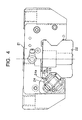
- Fig. 4 shows a conventional motion guide device that requires rollers to cause a motion of a movable member.
- rollers 23 located in a loaded range between roller rolling surfaces 21a and 22a are forced to move in a rolling motion so that a relative motion of the movable block 21 is allowed.
- a ball which is one type of rolling member, is usually formed into a sphere member that has an infinite number of rotation axes and is able to rotate in all directions without any restrictions.
- each of the rollers 23 is formed into a cylindrical body, with the result that each roller 23 is obliged to have only one rotation axis, when each roller 23 engages in a rolling motion.
- the movable direction of each roller 23 is confined to only one direction.
- orthogonality should be kept between the rotation axes of the rollers 23 and an advancement direction of the rollers 23.
- the conventional motion guide device adopts a step 24 formed on one edge of the roller rolling surface 21a of the movable block 21.
- the step 24 is shaped to have a contact protrusion 24a, to which one end surface of each roller 23 is permitted to be contacted, the one end surface being orthogonal to the rotation axis direction thereof.
- the presence of the contact protrusion 24a prevents the rollers 23 to be skewed (refer to Japanese Patent Laid-open (KOKAI) publication No. 2002-54633).
- This contact protrusion 24a may be formed, as illustrated in Fig. 4, on only one-side end surface of the rolling roller surface 21a in the axis-line direction thereof or may be formed on both-side end surfaces thereof.
- the step is formed on only one side of the rolling roller surface and an iron plate is disposed on the other side of the rolling roller surface so as to face and push each roller so that a gap between the rollers and the rolling roller surface is adjusted.
- the conventional contact protrusion is therefore made of metal whose strength is larger (for example, a metal made of the same material as that used to form the roller rolling surface of the movable block). It has long been common knowledge to prevent the skews of the rollers using contact between metal members.
- the present invention has been conceived in consideration of the above matters, and an object of the present invention is to provide a motion guide device capable of not only preventing the skews of the rollers but also reducing the slide resistance occurring when the movable member slides along the track member.
- the present invention provides a motion guide device comprising a track member having a roller rolling surface thereon; a movable member having a roller circulation passage including a loaded roller rolling surface located to be opposed to the roller rolling surface and being arranged to the track member to be movable relatively to the track member; a plurality of rollers, each made of metal, disposed in the roller circulation passage with a rotation axis of each of the rollers parallel to each other to thereby circulate in response to a relative motion of the movable member to the track member; and a roller retainer to retain the plurality of rollers rotatably and slidably.
- the movable member has a contact protrusion formed thereon and made of only resin, not metal, to thereby allow the contact protrusion to come in contact with an axis-line-direction end surface of each of the rollers that roll along the loaded roller rolling surface.
- the contact protrusion made to prevent the skews and the end surface of the rollers are brought into contact with other through collisions between the resin and metal materials. Accordingly, a friction factor between the contact protrusion and the end surface reduces, thus lowering sliding resistance caused when the movable member slides along the track member. This makes the movable member move in a smooth and stable manner.
- the connections of the rollers with the roller retainer make it possible to strengthen resistance against the occurrence of skews. Hence the resin-made contact protrusions are able to prevent the rollers from being skewed.
- the roller retainer is placed to intervene between two of the rollers and is provided with a plurality of spacer members with two recessed surfaces on both sides thereof, each of the recessed surfaces being consistent in a shape with an outer circumferential surface of the roller located next to each roller, and a connection member placed to expand outwardly from a rotation-axis-direction end surface of each of the rollers and to connect the spacer members with each other.
- the contact protrusion is formed on a support member to prevent the rollers from coming off from the loaded roller rolling surface by establishing a link with the connection member of the roller retainer when the movable member is removed from the track member.
- the roller retainer is able to have both the functions of preventing the rollers from coming off when the movable member is removed from the trail member and preventing the rollers from being skewed.
- the linear motion guide device is provided with a linearly elongated track rail 1 serving as a track member and a movable block 2, which serves as a movable member, assembled with the track rail 1 so as to relatively be slidable along the track rail 1.
- a large number of rollers 3 which serve as a plurality of rolling members.
- the rollers 3 are made of metal and formed so as to roll.
- the track rail 1 is produced to have an approximate rectangle in section orthogonal to its longitudinal direction.
- a groove 1a composed of wall surfaces 1b and 1b and a bottom surface 1c is formed along the longitudinal direction.
- both the wall surfaces 1b and 1b are crossed at right angles.
- Each of the upper wall surface 1b and the lower wall surface 1b provides a roller rolling surface serving as a rolling member rolling portion along which the rollers 31 roll. That is, on the right and left sides of the tack rail 1 are formed of four roller rolling surfaces 1b in total, i.e., upper and lower rolling surfaces (two rolling surfaces) on each side. These roller rolling surfaces are formed in parallel to each other to extend along the track rail 1.
- the movable block 2 is provided with a central portion 2a facing an upper surface of the track rail 1 and side wall portions 2b and 2b respectively extending downward from both side ends of the central portion 2a and facing both of lateral side surfaces of the track rail 1.
- the central portion 2a has a steel-made main block 4, a resin-made circulation passage forming structure built in the main block 4, and a pair of side lids 5 and 5 loaded on both lateral surfaces of the main block 4 in which the resin-made circulation passage forming structure is built, both the lateral surfaces being along a moving direction of the main block 4.
- each protrusion 4c and 4c On side wall portions 4b and 4b of the main block 4, protrusions 4c and 4c are formed, the shape of each protrusion 4c being consistent of the shape of each groove 1a formed on each side surface of the track rail 1.
- two loaded roller rolling surfaces 4d and 4d serving as loaded rolling member rolling portions, each loaded roller rolling surface 4d facing each roller rolling surface 1b.
- the loaded roller rolling surfaces 4d are made up of four rolling surfaces in total (i.e., two rolling surfaces (upper and lower rolling surfaces) on each of both right and left side wall portions 4b and 4b of the main block 4). These loaded roller rolling surfaces 4d extend in parallel with each other in the moving direction along which the movable block 2 is moved.
- roller escape passages 7 and 7 which are two in total on each side, and a U-shaped rolling direction changing passage.
- the roller escape passages 7 and 7 are formed to be in parallel with each other and located, predetermined distance apart, from the upper and lower two loaded roller rolling surfaces 4d and 4d, respectively.
- the rolling direction changing passage is formed to mutually connect each of the loaded roller rolling surfaces 4d and 4d and both ends of each of the roller escape passages 7 and 7 to have the roller 3 circulated therethrough.
- These loaded roller rolling surface 4d, rolling direction changing passage, and roller escape passage 7 compose a roller circulation passage.
- the roller escape passages 7 are formed by four in total, that is, two roller escape passages 7 and 7 at predetermined upper and lower positions in each of the right and left side wall portions 2b and 2b of the movable block 2.
- the rolling direction changing passage connects the upper loaded roller rolling surface 4d and the lower roller escape passage 7 as well as the lower loaded roller rolling surface 4d and the upper roller escape passage 7 so that both the connected passages an overhead crossing with each other.
- the roller circulation passages are formed by four in total, i.e., two in and on each of the lateral side wall portions 2b and 2b, respectively. There are produced two roller circulation passages. Each roller circulation passage is formed to locate in the same plane, with the result that the rollers 3 can circulate two-dimensionally along each roller circulation passage. On each side of the movable block 2, the two planes in which the two roller circulation passages are respectively located crosses with each other at right angles, and one roller circulation passage is arranged at an inner position than the remaining roller circulation passage.
- the plural rollers 3 are disposed in each roller circulation passage, with rotation axes of the rollers 3 in parallel with each other.
- the rollers 3 are mutually connected by a roller retainer 10 so that a chain of rollers 3 are produced.
- the rollers 3 are retained rotatably and slidably by the roller retainer 10 and are able to circulate along each given roller circulation passage.
- Fig. 2 shows the rollers 3 retained by the roller retainer 10.
- each spacer member 10b there is a spacer member 10b.
- spacer members 10b there are disposed a plurality of spacer members 10b in each train of the rollers 3.
- On each side of each space member 10b is formed a recess of which curvature agrees with an outer curvature of each adjacent roller 3.
- the spacer members 10b are mutually coupled by a pair of connection members 10d and 10d located so as to expand outwardly from each end surface in the rotation axis directions of the rollers 3.
- the resin-made circulation passage forming structure is provided with support members 11 and 11, escape passage forming members 14, and direction changing passage forming members 8.
- the support members 11 and 11 which extend along side edges of both the loaded roller rolling surfaces 4d and 4d, are disposed to prevent the rollers 3 coming off from the loaded roller rolling surfaces 4d and 4d when the movable block 2 is removed from the track rail 1.
- the escape passage forming members 14 are placed to form a roller escape passage for the rollers 3, while the direction changing passage forming members 8 are disposed to form a direction changing passage for the rollers 3.
- the support members 11 and 11, escape passage forming members 14, and direction changing passage forming members 8 are respectively formed as different members separated from the main block 4 and are made of resin, and then built into the main block 4.
- Each of the resin-made support members 11 has first, second and third support members 11a, 11b and 11c each formed into a thin and long-scale member made of a resin material, and is constructed by making the first to third members 11 a to 11c into one unit.
- the first support member 11a is located under the lower rollers 3
- the second support member 11b is located between the lower rollers 3 and the upper rollers 3
- the third support member 11c is located over the upper rollers 3.
- Each of the support members 11 and 11 is clipped between the pair of side lids 5 and 5 or the paired direction changing passage forming members 8 and 8, so that each support member 11 whose both ends is supported and fastened to the movable block 2.
- each support member 11 is able to link with the connection member 10d of the roller retainer 10 to prevent the roller from coming off from the loaded roller rolling surfaces 4d.
- the first, second and third support members 11a, 11b and 11c have contact protrusions 16 and 16 that are able to come into contact with end surfaces of each of the rollers 3 in the axis-line direction thereof (refer to Fig. 3).
- the escape passage forming members 14 is composed of a pair of pipe halves 14a and 14b produced by dividing a pipe material into two members in a direction orthogonal to an axis-line direction of the pipe.
- Each of the pipe halves 14a and 14b is provided a groove whose shape agrees with that of each roller 3 and continues along its longitudinal direction, and a guide groove to guide the connection member 10d of the roller retainer 10.
- the direction changing passage forming members 8 has the U-shaped direction changing passages which are formed in the member 8 to mutually cross in an overhead crossing. In this direction changing passage is formed the guide groove to guide the connection member 10d of the roller retainer 10.
- Each side lid 5, which has a cross section consistent with that of the main block 4, includes a central portion 5a and side wall portions 5b and 5b.
- formed is an outer guide portion of the outer-side roller circulation passage.
- the direction changing passage forming members 8 and 8 are built in.
- the side lids 5 and 5 are secured on both moving-directional sides of the main block 4. Bolts are inserted into bolt insertion holes formed in the side lids 5 and 5, and the bolts are screwed into screw holes formed in the end surfaces of the main block 4, so that the side lids 5 and 5 can be fastened and fixed to the main block 4.
- lubricant supply plates 12 and 12 On an inner side of each of the side lids 5 and 5, there are placed lubricant supply plates 12 and 12 to supply lubricant to the loaded roller rolling surfaces of the main block 4.
- end plates 13 and 13 are fastened, respectively.
- Each of the end plates 13 and 13 is consistent in their cross sections to the main block 4 and has a central portion 13a and side wall portions 13b and 13b.
- the end plates 13 and 13 are fixed to the side lids 5 and 5, respectively, by using screws.
- a sealing portion 13c is formed along an inner circumferential edge of each end plate 13, the inner circumferential edge being opposed to the track rail 1.
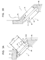
- Fig. 3A shows in detail a section, in which one upper roller 3 rolls between the track rail 1 and the movable block 2, which is concerned with the present embodiment.
- Fig. 3B shows a comparative example to the present embodiment.
- contact protrusions 16 and 16 are formed, respectively.
- Each of the contact protrusions 16 and 16 is able to contact each of axis-line-direction both end surfaces 3a and 3a of each roller 3 that rolls on the loaded roller rolling surface 4d.
- the contact protrusions 16 and 16 are located outwardly more than the orbit of the rotation axis 3b of each roller 3 rolling the loaded roller rolling surface 4d and separated by the same distance from the loaded roller rolling surface 4d.
- a distance L+ ⁇ L between the contact protrusions 16 and 16 is determined such that the distance L+ ⁇ L is slightly larger than a length L of each roller 3 in a rotation-axis direction thereof so as to obtain a clearance ⁇ L in the rotation-axis direction.
- the contact protrusions 16 and 16 are made of only a resin; no metal constituent is included in the materials of the protrusions 16. Therefore, contact between the end surfaces 3a of each roller 3 and the contact protrusions 16 for preventing the skews of the rollers 3 is carried out between resin and metal materials.
- a friction factor between the end surfaces 3a and the contact protrusions 16 reduces.
- sliding resistance caused when the movable block 2 slidably moves along the track rail 1 can also be lowered, thus providing a stable move of the movable block 2.
- roller retainer 10 forms up the rollers 3 in line in a predetermined attitude, it is possible to avoid the rollers 3 from being skewed. Even when the rollers 3 is skewed, an elastic restoration force provided by the pair of connection members 10d and 10d is able to get rid of the skews, resulting in that the rollers 3 are able to again retain its rotation axis at right angles. A combined use of the resin-made contact protrusions 16 and 16 and the roller retainer 10 steadily prevents the rollers 3 from being skewed.
- Fig. 3B exemplifies another structure, in which a step 17 is formed on the loaded roller rolling surface 4d to produce a metal-made contact surface 17a and this contact surface 17a is positioned to come in contact with one end surface 3a of each roller 3. This structure is able to prevent the skews of the rollers 3 as well.
- the skew-preventing contact surface 17a is made of metal, it should be necessary that the surface 17a be subjected to higher-precision grinding work and an escape groove 18 be formed at the root of the step 17.
- the present embodiment employs the resin-made contact protrusions 16, so that it is unnecessary to apply various kinds of work, such as grinding, to the contact protrusions 16. It is therefore possible to manufacture the motion guide device in a cost saving manner.
- the present embodiment there is an additional advantage about the prevention of one-sided contact of the rollers 3. If the paired contact protrusions 16 and 16 with each roller 3 therebetween are located at different distances from the roller rolling surface 4d, there is a fear that rollers 3 are brought into contact with one-side contact protrusion 16 (i.e., one-sided contact) when the rollers 3 are skewed.
- the device according to the present embodiment is structured to have the paired contact protrusions 16 and 16 located at the same height positions, thus preventing such one-sided contact.
- the contact protrusions and the end surfaces of the rollers are brought into contact with other through collisions between the resin and metal materials. Accordingly, a friction factor between the contact protrusions and the end surfaces reduces, thus lowering sliding resistance caused when the movable member slides along the track rail, thus making the movable member move in a smooth and stable manner.
- the connections of the rollers with the roller retainer make it possible to strengthen resistance against the occurrence of skews. Hence the resin-made contact protrusions are able to prevent the rollers from being skewed.
- the present embodiment is particularly effective in cases where the diameter of each roller is so small that a contact surface to be contacted with the end surfaces of the roller cannot be secured.
- the motion guide device directed to a linear motion guide the motion is not limited to such a linear motion.
- the present invention can also be applied to a motion guide device to guide a curved motion.
- the support members, escape passage forming members, and direction changing passage forming members can be formed as one unit with the main block by the use of insert molding requiring the main block to be inserted.
Landscapes
- Engineering & Computer Science (AREA)
- General Engineering & Computer Science (AREA)
- Mechanical Engineering (AREA)
- Bearings For Parts Moving Linearly (AREA)
Abstract
Description
- The present invention relates to a motion guide device for guiding a liner motion or a curved motion of an object to be guided, and in particular, to a rolling type of motion guide device in which rollers to guide a rolling motion is disposed between a track member and a movable member relatively movable to the track member.
- In general, a motion guide device is provided with a track rail, a movable block disposed movably along the track rail, and a plurality of rollers disposed between the track rail and the movable block. Fig. 4 shows a conventional motion guide device that requires rollers to cause a motion of a movable member. When the
movable block 21 moves relatively to atrack rail 22,rollers 23 located in a loaded range betweenroller rolling surfaces 21a and 22a are forced to move in a rolling motion so that a relative motion of themovable block 21 is allowed. - A ball, which is one type of rolling member, is usually formed into a sphere member that has an infinite number of rotation axes and is able to rotate in all directions without any restrictions. In contrast, each of the
rollers 23 is formed into a cylindrical body, with the result that eachroller 23 is obliged to have only one rotation axis, when eachroller 23 engages in a rolling motion. In other words, the movable direction of eachroller 23 is confined to only one direction. In order to allow therollers 23 to have rolling motions with no slip, orthogonality should be kept between the rotation axes of therollers 23 and an advancement direction of therollers 23. - In the conventional motion guide device that employs the
rollers 23, if parallelism between theroller rolling surface 21a of themovable block 21 and the roller rolling surface 22a of thetrack rail 22 is lost or an offset load is applied to themovable block 21, there are some cases where the orthogonality between the rotation axes of therollers 23 and an advancement direction of therollers 23 is lost as well. The phenomenon that therollers 23 are skewed against the normal rotation axes thereof is called "skew." - In order to prevent the skew phenomenon, the conventional motion guide device adopts a
step 24 formed on one edge of theroller rolling surface 21a of themovable block 21. Thestep 24 is shaped to have acontact protrusion 24a, to which one end surface of eachroller 23 is permitted to be contacted, the one end surface being orthogonal to the rotation axis direction thereof. The presence of thecontact protrusion 24a prevents therollers 23 to be skewed (refer to Japanese Patent Laid-open (KOKAI) publication No. 2002-54633). Thiscontact protrusion 24a may be formed, as illustrated in Fig. 4, on only one-side end surface of therolling roller surface 21a in the axis-line direction thereof or may be formed on both-side end surfaces thereof. Alternatively, the step is formed on only one side of the rolling roller surface and an iron plate is disposed on the other side of the rolling roller surface so as to face and push each roller so that a gap between the rollers and the rolling roller surface is adjusted. - However, when the rollers are skewed, a force pressing the contact protrusion becomes extremely larger, due to the inclination of the rollers. The conventional contact protrusion is therefore made of metal whose strength is larger (for example, a metal made of the same material as that used to form the roller rolling surface of the movable block). It has long been common knowledge to prevent the skews of the rollers using contact between metal members.
- However, the contact between metal members causes a higher friction factor, thereby increasing slide resistance occurring when the movable block slides along the track rail. Therefore, it may be difficult to obtain smooth and stable motions of the movable block.
- The present invention has been conceived in consideration of the above matters, and an object of the present invention is to provide a motion guide device capable of not only preventing the skews of the rollers but also reducing the slide resistance occurring when the movable member slides along the track member.
- In order to accomplish the above object, the present invention provides a motion guide device comprising a track member having a roller rolling surface thereon; a movable member having a roller circulation passage including a loaded roller rolling surface located to be opposed to the roller rolling surface and being arranged to the track member to be movable relatively to the track member; a plurality of rollers, each made of metal, disposed in the roller circulation passage with a rotation axis of each of the rollers parallel to each other to thereby circulate in response to a relative motion of the movable member to the track member; and a roller retainer to retain the plurality of rollers rotatably and slidably. The movable member has a contact protrusion formed thereon and made of only resin, not metal, to thereby allow the contact protrusion to come in contact with an axis-line-direction end surface of each of the rollers that roll along the loaded roller rolling surface.
- Thus, in the present invention, even though rollers are skewed, the contact protrusion made to prevent the skews and the end surface of the rollers are brought into contact with other through collisions between the resin and metal materials. Accordingly, a friction factor between the contact protrusion and the end surface reduces, thus lowering sliding resistance caused when the movable member slides along the track member. This makes the movable member move in a smooth and stable manner. In addition, the connections of the rollers with the roller retainer make it possible to strengthen resistance against the occurrence of skews. Hence the resin-made contact protrusions are able to prevent the rollers from being skewed.
- Preferably, the roller retainer is placed to intervene between two of the rollers and is provided with a plurality of spacer members with two recessed surfaces on both sides thereof, each of the recessed surfaces being consistent in a shape with an outer circumferential surface of the roller located next to each roller, and a connection member placed to expand outwardly from a rotation-axis-direction end surface of each of the rollers and to connect the spacer members with each other.
- Still preferably, the contact protrusion is formed on a support member to prevent the rollers from coming off from the loaded roller rolling surface by establishing a link with the connection member of the roller retainer when the movable member is removed from the track member.
- Thus, the roller retainer is able to have both the functions of preventing the rollers from coming off when the movable member is removed from the trail member and preventing the rollers from being skewed.
- Other objects and aspects of the present invention will become apparent from the following description and embodiments with reference to the accompanying drawings in which:
- Fig. 1 is a disassembled perspective view explaining a linear motion guide device according to an embodiment of the present invention;
- Fig. 2 is a perspective view showing rollers retained by a roller retainer;
- Fig. 3A is a detailed partial section showing a roller-supporting structure according to the embodiment, in which a roller rolls between a track rail and a movable block;
- Fig. 3B is a detailed partial section showing a roller-supporting structure according to a comparative example, in which a roller rolls between a track rail and a movable block; and
- Fig. 4 shows the front view of a conventional motion guide device.
- A preferred embodiment of the present invention will now be described together with accompanying drawings.
- Referring to Figs. 1 to 3A and 3B, a linear motion guide device according to an embodiment of the present invention will now be described.
- The linear motion guide device is provided with a linearly elongated track rail 1 serving as a track member and a
movable block 2, which serves as a movable member, assembled with the track rail 1 so as to relatively be slidable along the track rail 1. Between the track rail 1 and themovable block 2, there are provided a large number ofrollers 3 which serve as a plurality of rolling members. Therollers 3 are made of metal and formed so as to roll. - To be specific, the track rail 1 is produced to have an approximate rectangle in section orthogonal to its longitudinal direction. On each of both lateral sides of the track rail 1, a
groove 1a composed ofwall surfaces bottom surface 1c is formed along the longitudinal direction. - In each
groove 1a, both thewall surfaces upper wall surface 1b and thelower wall surface 1b provides a roller rolling surface serving as a rolling member rolling portion along which the rollers 31 roll. That is, on the right and left sides of the tack rail 1 are formed of fourroller rolling surfaces 1b in total, i.e., upper and lower rolling surfaces (two rolling surfaces) on each side. These roller rolling surfaces are formed in parallel to each other to extend along the track rail 1. - The
movable block 2 is provided with acentral portion 2a facing an upper surface of the track rail 1 andside wall portions central portion 2a and facing both of lateral side surfaces of the track rail 1. - The
central portion 2a has a steel-made main block 4, a resin-made circulation passage forming structure built in the main block 4, and a pair of side lids 5 and 5 loaded on both lateral surfaces of the main block 4 in which the resin-made circulation passage forming structure is built, both the lateral surfaces being along a moving direction of the main block 4. - On
side wall portions protrusions protrusion 4c being consistent of the shape of eachgroove 1a formed on each side surface of the track rail 1. On each of theprotrusions roller rolling surfaces roller rolling surface 4d facing eachroller rolling surface 1b. In other words, the loadedroller rolling surfaces 4d are made up of four rolling surfaces in total (i.e., two rolling surfaces (upper and lower rolling surfaces) on each of both right and leftside wall portions roller rolling surfaces 4d extend in parallel with each other in the moving direction along which themovable block 2 is moved. - In the
side wall portions movable block 2, there are formed upper and lowerroller escape passages side wall portion 2b, theroller escape passages roller rolling surfaces - The rolling direction changing passage is formed to mutually connect each of the loaded
roller rolling surfaces roller escape passages roller 3 circulated therethrough. These loadedroller rolling surface 4d, rolling direction changing passage, androller escape passage 7 compose a roller circulation passage. - Of these components, the
roller escape passages 7 are formed by four in total, that is, tworoller escape passages side wall portions movable block 2. On each side of themovable block 2, the rolling direction changing passage connects the upper loadedroller rolling surface 4d and the lowerroller escape passage 7 as well as the lower loadedroller rolling surface 4d and the upperroller escape passage 7 so that both the connected passages an overhead crossing with each other. - The roller circulation passages are formed by four in total, i.e., two in and on each of the lateral
side wall portions rollers 3 can circulate two-dimensionally along each roller circulation passage. On each side of themovable block 2, the two planes in which the two roller circulation passages are respectively located crosses with each other at right angles, and one roller circulation passage is arranged at an inner position than the remaining roller circulation passage. - The
plural rollers 3 are disposed in each roller circulation passage, with rotation axes of therollers 3 in parallel with each other. Therollers 3 are mutually connected by aroller retainer 10 so that a chain ofrollers 3 are produced. Therollers 3 are retained rotatably and slidably by theroller retainer 10 and are able to circulate along each given roller circulation passage. Fig. 2 shows therollers 3 retained by theroller retainer 10. - Between the
rollers spacer member 10b. Thus, there are disposed a plurality ofspacer members 10b in each train of therollers 3. On each side of eachspace member 10b is formed a recess of which curvature agrees with an outer curvature of eachadjacent roller 3. Thespacer members 10b are mutually coupled by a pair ofconnection members rollers 3. - As shown in Fig. 1, the resin-made circulation passage forming structure is provided with
support members passage forming members 14, and direction changingpassage forming members 8. - Among these components, the
support members roller rolling surfaces rollers 3 coming off from the loadedroller rolling surfaces movable block 2 is removed from the track rail 1. The escapepassage forming members 14 are placed to form a roller escape passage for therollers 3, while the direction changingpassage forming members 8 are disposed to form a direction changing passage for therollers 3. - The
support members passage forming members 14, and direction changingpassage forming members 8 are respectively formed as different members separated from the main block 4 and are made of resin, and then built into the main block 4. - Each of the resin-made
support members 11 has first, second andthird support members third members 11 a to 11c into one unit. Thefirst support member 11a is located under thelower rollers 3, thesecond support member 11b is located between thelower rollers 3 and theupper rollers 3, and thethird support member 11c is located over theupper rollers 3. Each of thesupport members passage forming members support member 11 whose both ends is supported and fastened to themovable block 2. - In cases where the
movable block 2 is removed from the track rail 1, eachsupport member 11 is able to link with theconnection member 10d of theroller retainer 10 to prevent the roller from coming off from the loadedroller rolling surfaces 4d. Though will be detailed later, the first, second andthird support members contact protrusions rollers 3 in the axis-line direction thereof (refer to Fig. 3). - The escape
passage forming members 14 is composed of a pair ofpipe halves roller 3 and continues along its longitudinal direction, and a guide groove to guide theconnection member 10d of theroller retainer 10. - The direction changing
passage forming members 8 has the U-shaped direction changing passages which are formed in themember 8 to mutually cross in an overhead crossing. In this direction changing passage is formed the guide groove to guide theconnection member 10d of theroller retainer 10. - Each side lid 5, which has a cross section consistent with that of the main block 4, includes a
central portion 5a andside wall portions side wall portions side wall portions passage forming members - On an inner side of each of the side lids 5 and 5, there are placed
lubricant supply plates - To an outer side of each of the side lids 5 and 5 (i.e., corresponding to both moving-directional side surfaces of the movable block),
end plates end plates central portion 13a andside wall portions end plates portion 13c is formed along an inner circumferential edge of eachend plate 13, the inner circumferential edge being opposed to the track rail 1. - Fig. 3A shows in detail a section, in which one
upper roller 3 rolls between the track rail 1 and themovable block 2, which is concerned with the present embodiment. In contrast, Fig. 3B shows a comparative example to the present embodiment. - On the
support members contact protrusions contact protrusions end surfaces roller 3 that rolls on the loadedroller rolling surface 4d. The contact protrusions 16 and 16 are located outwardly more than the orbit of therotation axis 3b of eachroller 3 rolling the loadedroller rolling surface 4d and separated by the same distance from the loadedroller rolling surface 4d. A distance L+ÄL between thecontact protrusions roller 3 in a rotation-axis direction thereof so as to obtain a clearance ÄL in the rotation-axis direction. Contact of the end surfaces 3a and 3a of eachroller 3 to thecontact protrusions rotation axis 3b of eachroller 3 from being shifted from right angles (i.e., from having a tilt to an orthogonal direction) to the moving direction of therollers 3 during rolling motions of therollers 3. - In the present embodiment, the
contact protrusions protrusions 16. Therefore, contact between the end surfaces 3a of eachroller 3 and thecontact protrusions 16 for preventing the skews of therollers 3 is carried out between resin and metal materials. When the rollers are in a rolling motion, a friction factor between the end surfaces 3a and thecontact protrusions 16 reduces. Hence, sliding resistance caused when themovable block 2 slidably moves along the track rail 1 can also be lowered, thus providing a stable move of themovable block 2. - In addition, since the
roller retainer 10 forms up therollers 3 in line in a predetermined attitude, it is possible to avoid therollers 3 from being skewed. Even when therollers 3 is skewed, an elastic restoration force provided by the pair ofconnection members rollers 3 are able to again retain its rotation axis at right angles. A combined use of the resin-madecontact protrusions roller retainer 10 steadily prevents therollers 3 from being skewed. - Fig. 3B exemplifies another structure, in which a
step 17 is formed on the loadedroller rolling surface 4d to produce a metal-madecontact surface 17a and thiscontact surface 17a is positioned to come in contact with oneend surface 3a of eachroller 3. This structure is able to prevent the skews of therollers 3 as well. - However, in this case, the skew-preventing
contact surface 17a is made of metal, it should be necessary that thesurface 17a be subjected to higher-precision grinding work and anescape groove 18 be formed at the root of thestep 17. - As described above, the present embodiment employs the resin-made
contact protrusions 16, so that it is unnecessary to apply various kinds of work, such as grinding, to thecontact protrusions 16. It is therefore possible to manufacture the motion guide device in a cost saving manner. - In the present embodiment, there is an additional advantage about the prevention of one-sided contact of the
rollers 3. If the pairedcontact protrusions roller 3 therebetween are located at different distances from theroller rolling surface 4d, there is a fear thatrollers 3 are brought into contact with one-side contact protrusion 16 (i.e., one-sided contact) when therollers 3 are skewed. By contrast, the device according to the present embodiment is structured to have the pairedcontact protrusions - As described above, in the present embodiment, even though rollers are skewed, the contact protrusions and the end surfaces of the rollers are brought into contact with other through collisions between the resin and metal materials. Accordingly, a friction factor between the contact protrusions and the end surfaces reduces, thus lowering sliding resistance caused when the movable member slides along the track rail, thus making the movable member move in a smooth and stable manner. In addition, the connections of the rollers with the roller retainer make it possible to strengthen resistance against the occurrence of skews. Hence the resin-made contact protrusions are able to prevent the rollers from being skewed.
- The present embodiment is particularly effective in cases where the diameter of each roller is so small that a contact surface to be contacted with the end surfaces of the roller cannot be secured. Though the foregoing embodiment has been described about the motion guide device directed to a linear motion guide, the motion is not limited to such a linear motion. The present invention can also be applied to a motion guide device to guide a curved motion. Further, the support members, escape passage forming members, and direction changing passage forming members can be formed as one unit with the main block by the use of insert molding requiring the main block to be inserted.
- For the sake of completeness, it should be mentioned that the embodiment and modifications explained so far are not definitive lists of possible embodiments of the present invention. The expert will appreciate that it is possible to combine the various construction details or to supplement or modify them by measures known from the prior art without departing from the basic inventive principle.
Claims (3)
- A motion guide device comprising:a track member having a roller rolling surface thereon;a movable member having a roller circulation passage including a loaded roller rolling surface located to be opposed to the roller rolling surface and being arranged to the track member to be movable relatively to the track member;a plurality of rollers, each made of metal, disposed in the roller circulation passage with a rotation axis of each of the rollers parallel to each other to thereby circulate in response to a relative motion of the movable member to the track member; anda roller retainer to retain the plurality of rollers rotatably and slidably,wherein the movable member has a contact protrusion formed thereon and made of only resin, not metal, to thereby allow the contact protrusion to come in contact with an axis-line-direction end surface of each of the rollers that roll along the loaded roller rolling surface.
- The motion guide device according to claim 1, wherein the roller retainer is placed to intervene between two of the rollers and is provided with a plurality of spacer members with two recessed surfaces on both sides thereof, each of the recessed surfaces being consistent in a shape with an outer circumferential surface of the roller located next to each roller, and a connection member placed to expand outwardly from a rotation-axis-direction end surface of each of the rollers and to connect the spacer members with each other.
- The motion guide device according to claim 1 or 2, wherein the contact protrusion is formed on a support member to prevent the rollers from coming off from the loaded roller rolling surface by establishing a link with the connection member of the roller retainer when the movable member is removed form the track member.
Applications Claiming Priority (2)
| Application Number | Priority Date | Filing Date | Title |
|---|---|---|---|
| JP2002285422 | 2002-09-30 | ||
| JP2002285422A JP2004124956A (en) | 2002-09-30 | 2002-09-30 | Movement guide device |
Publications (2)
| Publication Number | Publication Date |
|---|---|
| EP1403541A1 true EP1403541A1 (en) | 2004-03-31 |
| EP1403541B1 EP1403541B1 (en) | 2005-07-27 |
Family
ID=31973389
Family Applications (1)
| Application Number | Title | Priority Date | Filing Date |
|---|---|---|---|
| EP20030022208 Expired - Lifetime EP1403541B1 (en) | 2002-09-30 | 2003-09-30 | Linear rolling element bearing with rollers retained in a flexible cage |
Country Status (5)
| Country | Link |
|---|---|
| EP (1) | EP1403541B1 (en) |
| JP (1) | JP2004124956A (en) |
| CN (1) | CN1306180C (en) |
| DE (1) | DE60301109T2 (en) |
| TW (1) | TWI299772B (en) |
Cited By (2)
| Publication number | Priority date | Publication date | Assignee | Title |
|---|---|---|---|---|
| US7798717B2 (en) | 2006-11-28 | 2010-09-21 | Robert Bosch Gmbh | Spacer |
| US20180073558A1 (en) | 2015-04-09 | 2018-03-15 | Thk Co., Ltd. | Motion guide apparatus |
Families Citing this family (10)
| Publication number | Priority date | Publication date | Assignee | Title |
|---|---|---|---|---|
| KR101238991B1 (en) * | 2005-03-18 | 2013-03-04 | 티에치케이 가부시끼가이샤 | Guide device |
| JP2007239829A (en) * | 2006-03-07 | 2007-09-20 | Nsk Ltd | Linear guide device |
| JP5223713B2 (en) * | 2009-02-12 | 2013-06-26 | 日本精工株式会社 | Linear motion guide device |
| CN102122206B (en) | 2010-01-08 | 2012-12-19 | 鸿富锦精密工业(深圳)有限公司 | Keyboard having support device |
| JP5358652B2 (en) * | 2011-11-09 | 2013-12-04 | Thk株式会社 | Exercise guidance device |
| TWM437400U (en) | 2011-12-30 | 2012-09-11 | Kuo-Le Tsao | Roller type linear slider |
| TWM437398U (en) * | 2012-01-05 | 2012-09-11 | Kuo-Le Tsao | Linear slider having ball retainer |
| JP5461608B2 (en) * | 2012-03-14 | 2014-04-02 | Thk株式会社 | Exercise equipment |
| CN104565032B (en) * | 2014-12-31 | 2017-06-23 | 丽水市吴越机械制造有限公司 | Linear slider, the processing technology of machining of slide block ball grooves and its grinding machine |
| CN117189777B (en) * | 2023-11-06 | 2024-02-20 | 江苏恒立精密工业有限公司 | Precise roller linear guide rail |
Citations (6)
| Publication number | Priority date | Publication date | Assignee | Title |
|---|---|---|---|---|
| EP0449595A2 (en) * | 1990-03-28 | 1991-10-02 | Thomson Industries, Inc. | Linear motion bearing |
| DE4311515A1 (en) * | 1993-04-07 | 1994-10-13 | Star Gmbh | Rolling-contact bearing for linear movements |
| DE4331014A1 (en) * | 1993-08-12 | 1995-03-09 | Schaeffler Waelzlager Kg | Linear roller bearing element |
| EP0838602A1 (en) * | 1996-05-13 | 1998-04-29 | Thk Co. Ltd. | Linear roller guide |
| US6287005B1 (en) * | 1998-11-25 | 2001-09-11 | Hiroshi Teramachi | Roller guiding apparatus |
| WO2001092738A1 (en) * | 2000-05-29 | 2001-12-06 | Thk Co., Ltd. | Linear motion guide device |
-
2002
- 2002-09-30 JP JP2002285422A patent/JP2004124956A/en active Pending
-
2003
- 2003-09-22 TW TW92126062A patent/TWI299772B/en not_active IP Right Cessation
- 2003-09-30 EP EP20030022208 patent/EP1403541B1/en not_active Expired - Lifetime
- 2003-09-30 CN CNB031649335A patent/CN1306180C/en not_active Expired - Lifetime
- 2003-09-30 DE DE2003601109 patent/DE60301109T2/en not_active Expired - Lifetime
Patent Citations (6)
| Publication number | Priority date | Publication date | Assignee | Title |
|---|---|---|---|---|
| EP0449595A2 (en) * | 1990-03-28 | 1991-10-02 | Thomson Industries, Inc. | Linear motion bearing |
| DE4311515A1 (en) * | 1993-04-07 | 1994-10-13 | Star Gmbh | Rolling-contact bearing for linear movements |
| DE4331014A1 (en) * | 1993-08-12 | 1995-03-09 | Schaeffler Waelzlager Kg | Linear roller bearing element |
| EP0838602A1 (en) * | 1996-05-13 | 1998-04-29 | Thk Co. Ltd. | Linear roller guide |
| US6287005B1 (en) * | 1998-11-25 | 2001-09-11 | Hiroshi Teramachi | Roller guiding apparatus |
| WO2001092738A1 (en) * | 2000-05-29 | 2001-12-06 | Thk Co., Ltd. | Linear motion guide device |
Cited By (3)
| Publication number | Priority date | Publication date | Assignee | Title |
|---|---|---|---|---|
| US7798717B2 (en) | 2006-11-28 | 2010-09-21 | Robert Bosch Gmbh | Spacer |
| US20180073558A1 (en) | 2015-04-09 | 2018-03-15 | Thk Co., Ltd. | Motion guide apparatus |
| US10174787B2 (en) | 2015-04-09 | 2019-01-08 | Thk Co., Ltd. | Motion guide apparatus |
Also Published As
| Publication number | Publication date |
|---|---|
| JP2004124956A (en) | 2004-04-22 |
| TW200409870A (en) | 2004-06-16 |
| TWI299772B (en) | 2008-08-11 |
| CN1497193A (en) | 2004-05-19 |
| DE60301109D1 (en) | 2005-09-01 |
| DE60301109T2 (en) | 2006-03-30 |
| CN1306180C (en) | 2007-03-21 |
| EP1403541B1 (en) | 2005-07-27 |
Similar Documents
| Publication | Publication Date | Title |
|---|---|---|
| JP3243415B2 (en) | Sliding guide device and its end rolling element chain | |
| US6116783A (en) | Ball chain | |
| CN101484712B (en) | Linear guidance device | |
| EP1403541B1 (en) | Linear rolling element bearing with rollers retained in a flexible cage | |
| CN101213383B (en) | Rolling guide device and manufacturing method thereof | |
| EP1186790B1 (en) | Rolling element spacers for rolling guide units | |
| JPH063211B2 (en) | Linear sliding bearing and method of assembling linear sliding bearing | |
| CN104271972B (en) | Motion Guidance Device | |
| JP3263005B2 (en) | Rolling guide device | |
| US20100129012A1 (en) | Rolling element retainer | |
| WO2006022242A1 (en) | Rolling guiding device | |
| US7465094B2 (en) | Linear guide apparatus | |
| EP0594209A2 (en) | Linear motion rolling guide unit | |
| US6109789A (en) | Linear slide | |
| JP3343195B2 (en) | Roller chain | |
| EP0989314A1 (en) | Roller connected body and linear guide device using it | |
| US6328474B1 (en) | Linear guide device | |
| JPH10318257A (en) | Rolling body coupling body | |
| JP4340547B2 (en) | Guide unit with built-in roller chain | |
| TW202523988A (en) | Roller retainer, slider, and stroke slide | |
| JP3575027B2 (en) | Linear motion rolling guide unit | |
| JP2008175324A (en) | Ball connection body | |
| JP4619226B2 (en) | Rolling guide device | |
| CN100398852C (en) | Linear guide device with eccentric load prevention mechanism | |
| JP2001140879A (en) | Roller connector and roller guide device |
Legal Events
| Date | Code | Title | Description |
|---|---|---|---|
| PUAI | Public reference made under article 153(3) epc to a published international application that has entered the european phase |
Free format text: ORIGINAL CODE: 0009012 |
|
| AK | Designated contracting states |
Kind code of ref document: A1 Designated state(s): AT BE BG CH CY CZ DE DK EE ES FI FR GB GR HU IE IT LI LU MC NL PT RO SE SI SK TR |
|
| AX | Request for extension of the european patent |
Extension state: AL LT LV MK |
|
| 17P | Request for examination filed |
Effective date: 20040428 |
|
| RIN1 | Information on inventor provided before grant (corrected) |
Inventor name: FUJII, YUUKI,THK CO., LTD. Inventor name: MOCHIZUKI, HIROAKI,THK CO., LTD. Inventor name: HORIE, TAKUYA,THK CO., LTD. |
|
| 17Q | First examination report despatched |
Effective date: 20040526 |
|
| AKX | Designation fees paid |
Designated state(s): CH DE LI |
|
| GRAP | Despatch of communication of intention to grant a patent |
Free format text: ORIGINAL CODE: EPIDOSNIGR1 |
|
| GRAS | Grant fee paid |
Free format text: ORIGINAL CODE: EPIDOSNIGR3 |
|
| GRAA | (expected) grant |
Free format text: ORIGINAL CODE: 0009210 |
|
| AK | Designated contracting states |
Kind code of ref document: B1 Designated state(s): CH DE LI |
|
| REG | Reference to a national code |
Ref country code: CH Ref legal event code: EP |
|
| REF | Corresponds to: |
Ref document number: 60301109 Country of ref document: DE Date of ref document: 20050901 Kind code of ref document: P |
|
| REG | Reference to a national code |
Ref country code: CH Ref legal event code: NV Representative=s name: PATENTANWAELTE SCHAAD, BALASS, MENZL & PARTNER AG |
|
| PLBE | No opposition filed within time limit |
Free format text: ORIGINAL CODE: 0009261 |
|
| STAA | Information on the status of an ep patent application or granted ep patent |
Free format text: STATUS: NO OPPOSITION FILED WITHIN TIME LIMIT |
|
| 26N | No opposition filed |
Effective date: 20060428 |
|
| PGFP | Annual fee paid to national office [announced via postgrant information from national office to epo] |
Ref country code: DE Payment date: 20220620 Year of fee payment: 20 |
|
| PGFP | Annual fee paid to national office [announced via postgrant information from national office to epo] |
Ref country code: CH Payment date: 20220928 Year of fee payment: 20 |
|
| REG | Reference to a national code |
Ref country code: DE Ref legal event code: R071 Ref document number: 60301109 Country of ref document: DE |
|
| REG | Reference to a national code |
Ref country code: CH Ref legal event code: PL |