EP1403477A2 - Substrate used for exhaust gas purification and method of fabrication thereof - Google Patents
Substrate used for exhaust gas purification and method of fabrication thereof Download PDFInfo
- Publication number
- EP1403477A2 EP1403477A2 EP03021539A EP03021539A EP1403477A2 EP 1403477 A2 EP1403477 A2 EP 1403477A2 EP 03021539 A EP03021539 A EP 03021539A EP 03021539 A EP03021539 A EP 03021539A EP 1403477 A2 EP1403477 A2 EP 1403477A2
- Authority
- EP
- European Patent Office
- Prior art keywords
- partition wall
- transforming step
- wall ends
- amount
- passages
- Prior art date
- Legal status (The legal status is an assumption and is not a legal conclusion. Google has not performed a legal analysis and makes no representation as to the accuracy of the status listed.)
- Granted
Links
Images




Classifications
-
- B—PERFORMING OPERATIONS; TRANSPORTING
- B01—PHYSICAL OR CHEMICAL PROCESSES OR APPARATUS IN GENERAL
- B01D—SEPARATION
- B01D46/00—Filters or filtering processes specially modified for separating dispersed particles from gases or vapours
-
- F—MECHANICAL ENGINEERING; LIGHTING; HEATING; WEAPONS; BLASTING
- F01—MACHINES OR ENGINES IN GENERAL; ENGINE PLANTS IN GENERAL; STEAM ENGINES
- F01N—GAS-FLOW SILENCERS OR EXHAUST APPARATUS FOR MACHINES OR ENGINES IN GENERAL; GAS-FLOW SILENCERS OR EXHAUST APPARATUS FOR INTERNAL-COMBUSTION ENGINES
- F01N3/00—Exhaust or silencing apparatus having means for purifying, rendering innocuous, or otherwise treating exhaust
- F01N3/02—Exhaust or silencing apparatus having means for purifying, rendering innocuous, or otherwise treating exhaust for cooling, or for removing solid constituents of, exhaust
- F01N3/021—Exhaust or silencing apparatus having means for purifying, rendering innocuous, or otherwise treating exhaust for cooling, or for removing solid constituents of, exhaust by means of filters
- F01N3/022—Exhaust or silencing apparatus having means for purifying, rendering innocuous, or otherwise treating exhaust for cooling, or for removing solid constituents of, exhaust by means of filters characterised by specially adapted filtering structure, e.g. honeycomb, mesh or fibrous
- F01N3/0222—Exhaust or silencing apparatus having means for purifying, rendering innocuous, or otherwise treating exhaust for cooling, or for removing solid constituents of, exhaust by means of filters characterised by specially adapted filtering structure, e.g. honeycomb, mesh or fibrous the structure being monolithic, e.g. honeycombs
-
- B—PERFORMING OPERATIONS; TRANSPORTING
- B01—PHYSICAL OR CHEMICAL PROCESSES OR APPARATUS IN GENERAL
- B01J—CHEMICAL OR PHYSICAL PROCESSES, e.g. CATALYSIS OR COLLOID CHEMISTRY; THEIR RELEVANT APPARATUS
- B01J35/00—Catalysts, in general, characterised by their form or physical properties
- B01J35/50—Catalysts, in general, characterised by their form or physical properties characterised by their shape or configuration
- B01J35/56—Foraminous structures having flow-through passages or channels, e.g. grids or three-dimensional [3D] monoliths
- B01J35/57—Honeycombs
-
- B—PERFORMING OPERATIONS; TRANSPORTING
- B28—WORKING CEMENT, CLAY, OR STONE
- B28B—SHAPING CLAY OR OTHER CERAMIC COMPOSITIONS; SHAPING SLAG; SHAPING MIXTURES CONTAINING CEMENTITIOUS MATERIAL, e.g. PLASTER
- B28B11/00—Apparatus or processes for treating or working the shaped or preshaped articles
- B28B11/003—Apparatus or processes for treating or working the shaped or preshaped articles the shaping of preshaped articles, e.g. by bending
- B28B11/006—Making hollow articles or partly closed articles
-
- F—MECHANICAL ENGINEERING; LIGHTING; HEATING; WEAPONS; BLASTING
- F01—MACHINES OR ENGINES IN GENERAL; ENGINE PLANTS IN GENERAL; STEAM ENGINES
- F01N—GAS-FLOW SILENCERS OR EXHAUST APPARATUS FOR MACHINES OR ENGINES IN GENERAL; GAS-FLOW SILENCERS OR EXHAUST APPARATUS FOR INTERNAL-COMBUSTION ENGINES
- F01N3/00—Exhaust or silencing apparatus having means for purifying, rendering innocuous, or otherwise treating exhaust
- F01N3/02—Exhaust or silencing apparatus having means for purifying, rendering innocuous, or otherwise treating exhaust for cooling, or for removing solid constituents of, exhaust
- F01N3/021—Exhaust or silencing apparatus having means for purifying, rendering innocuous, or otherwise treating exhaust for cooling, or for removing solid constituents of, exhaust by means of filters
- F01N3/033—Exhaust or silencing apparatus having means for purifying, rendering innocuous, or otherwise treating exhaust for cooling, or for removing solid constituents of, exhaust by means of filters in combination with other devices
- F01N3/035—Exhaust or silencing apparatus having means for purifying, rendering innocuous, or otherwise treating exhaust for cooling, or for removing solid constituents of, exhaust by means of filters in combination with other devices with catalytic reactors
-
- F—MECHANICAL ENGINEERING; LIGHTING; HEATING; WEAPONS; BLASTING
- F01—MACHINES OR ENGINES IN GENERAL; ENGINE PLANTS IN GENERAL; STEAM ENGINES
- F01N—GAS-FLOW SILENCERS OR EXHAUST APPARATUS FOR MACHINES OR ENGINES IN GENERAL; GAS-FLOW SILENCERS OR EXHAUST APPARATUS FOR INTERNAL-COMBUSTION ENGINES
- F01N2240/00—Combination or association of two or more different exhaust treating devices, or of at least one such device with an auxiliary device, not covered by indexing codes F01N2230/00 or F01N2250/00, one of the devices being
- F01N2240/20—Combination or association of two or more different exhaust treating devices, or of at least one such device with an auxiliary device, not covered by indexing codes F01N2230/00 or F01N2250/00, one of the devices being a flow director or deflector
-
- Y—GENERAL TAGGING OF NEW TECHNOLOGICAL DEVELOPMENTS; GENERAL TAGGING OF CROSS-SECTIONAL TECHNOLOGIES SPANNING OVER SEVERAL SECTIONS OF THE IPC; TECHNICAL SUBJECTS COVERED BY FORMER USPC CROSS-REFERENCE ART COLLECTIONS [XRACs] AND DIGESTS
- Y10—TECHNICAL SUBJECTS COVERED BY FORMER USPC
- Y10S—TECHNICAL SUBJECTS COVERED BY FORMER USPC CROSS-REFERENCE ART COLLECTIONS [XRACs] AND DIGESTS
- Y10S264/00—Plastic and nonmetallic article shaping or treating: processes
- Y10S264/48—Processes of making filters
-
- Y—GENERAL TAGGING OF NEW TECHNOLOGICAL DEVELOPMENTS; GENERAL TAGGING OF CROSS-SECTIONAL TECHNOLOGIES SPANNING OVER SEVERAL SECTIONS OF THE IPC; TECHNICAL SUBJECTS COVERED BY FORMER USPC CROSS-REFERENCE ART COLLECTIONS [XRACs] AND DIGESTS
- Y10—TECHNICAL SUBJECTS COVERED BY FORMER USPC
- Y10S—TECHNICAL SUBJECTS COVERED BY FORMER USPC CROSS-REFERENCE ART COLLECTIONS [XRACs] AND DIGESTS
- Y10S55/00—Gas separation
- Y10S55/05—Methods of making filter
-
- Y—GENERAL TAGGING OF NEW TECHNOLOGICAL DEVELOPMENTS; GENERAL TAGGING OF CROSS-SECTIONAL TECHNOLOGIES SPANNING OVER SEVERAL SECTIONS OF THE IPC; TECHNICAL SUBJECTS COVERED BY FORMER USPC CROSS-REFERENCE ART COLLECTIONS [XRACs] AND DIGESTS
- Y10—TECHNICAL SUBJECTS COVERED BY FORMER USPC
- Y10S—TECHNICAL SUBJECTS COVERED BY FORMER USPC CROSS-REFERENCE ART COLLECTIONS [XRACs] AND DIGESTS
- Y10S55/00—Gas separation
- Y10S55/30—Exhaust treatment
Definitions
- the present invention relates to a substrate used for purifying exhaust gas and a method of fabricating the substrate.
- a particulate filter for trapping fine particles in the exhaust gas emitted from the combustion chamber of the internal combustion engine is disclosed in Japanese Unexamined Patent Publication No. 8-508199.
- This filter has a plurality of passages defined by a plurality of partition walls of a porous material and extending in parallel with each other. One end opening of one of each adjacent two passages is closed, while the other end opening of the other of the adjacent two passages is closed.
- the exhaust gas that has flowed into a passage of the filter therefore, flows into adjacent passages through the fine holes of the partition walls.
- the selected openings of the passages are closed by transforming and connecting the end portions of the partition walls into the form of a rectangular pyramid.
- a honeycombed structure of a porous material and a jig having a plurality of protrusions are prepared, and the jig is pressed against the end surface of the honeycombed structure so that the protrusions alternately enter the passages of the honeycombed structure.
- the partition wall ends may not be sufficiently connected and the openings of the passages may not be closed up completely.
- the object of this invention is to positively close up the passage openings of a substrate for purifying the exhaust gas.
- a method of fabricating a substrate used for purifying the exhaust gas comprising:
- a method in the first aspect of the invention, wherein the first transforming step and the second transforming step are executed at the same time.
- a third aspect of the invention there is provided a method, in the first aspect of the invention, wherein the second transforming step is executed after the first transforming step.
- a method in the first aspect of the invention wherein the amount of transformation of the partition wall ends in the first transforming step is smaller than the minimum amount required to close up a corresponding passage with the same partition wall ends, and the amount of transformation of the partition wall ends in the second transforming step is equal to the difference between the aforementioned minimum required amount and the transformation amount of the partition wall ends in the first transforming step.
- a fifth aspect of the invention there is provided a method, in the first aspect of the invention, wherein the amount of transformation of the partition wall ends in the first transforming step is smaller than the minimum amount required to close up a corresponding passage with the same partition wall ends, and the amount of transformation of the partition wall ends in the second transforming step is larger than the difference between the aforementioned required minimum amount and the transformation amount of the partition wall ends in the first transforming step.
- a sixth aspect of the invention there is provided a method, in the first aspect of the invention, wherein the cross section of the passages is a square and the partition wall ends closing the corresponding passages each form a portion in the shape of a substantially regular rectangular pyramid.
- a seventh aspect of the invention there is provided a method in the first aspect of the invention, wherein the cross section of the passages is a regular triangle and the partition wall ends closing the corresponding passages each form a portion in the shape of a substantially regular hexagonal pyramid.
- the pre-mold is formed of a porous material.
- a ninth aspect of the invention there is provided a method, in the first aspect of the invention, further comprising the third transforming step for transforming the partition wall ends at the second end of the pre-mold defining the other of the two adjacent passages in such a manner that the partition wall ends are collected toward the center of the corresponding passage and connected to each other, and the fourth transforming step for transforming the partition wall ends at the second end of the pre-mold in such a manner that the end surfaces of the partition walls at the second end of the pre-mold are depressed toward the center of the end surface.
- a method in the ninth aspect of the invention, wherein the first transforming step and the second transforming step are executed at the same time, and the third transforming step and the fourth transforming step are executed at the same time.
- a method in the ninth aspect of the invention wherein the amount of transformation of the partition wall ends in the first transforming step is smaller than the minimum amount required to close up the passages with the partition wall ends, the amount of transformation of the partition wall ends in the second transforming step is equal to the difference between the required minimum amount and the transformation amount of the partition wall ends in the first transforming step, the amount of transformation of the partition wall ends in the third transforming step is smaller than the minimum amount required to close up the passages with the partition wall ends, and the amount of transformation of the partition wall ends in the fourth transforming step is equal to the difference between the required minimum amount and the transformation amount of the partition wall ends in the third transforming step.
- a method in the ninth aspect of the invention wherein the amount of transformation of the partition wall ends in the first transforming step is smaller than the minimum amount required to close up the passages with the partition wall ends, the amount of transformation of the partition wall ends in the second transforming step is larger than the difference between the required minimum amount and the transformation amount of the partition wall ends in the first transforming step, the amount of transformation of the partition wall ends in the third transforming step is smaller than the minimum amount required to close up the passages with the partition wall ends, and the amount of transformation of the partition wall ends in the fourth transforming step is larger than the difference between the required minimum amount and the transformation amount of the partition wall ends in the third transforming step.
- a substrate used for purifying the exhaust gas comprising a first end, a second end, a plurality of partition walls extending between the first end and the second end, and a plurality of passages defined by the plurality of the partition walls, wherein the ends of a plurality of the partition walls at the first end of the substrate defining one of each two adjacent passages are collected toward the center of a corresponding passage and connected with each other, the end surface of the partition wall ends at the first end of the substrate being depressed toward the center of the end surface, and wherein the ends of a plurality of the partition walls at the second end of the substrate defining the remaining one of the two adjacent passages are collected toward the center of the corresponding passage and connected with each other, the end surface of the partition walls at the second end of the substrate being depressed toward the center of the end surface.
- a substrate in the 14th aspect of the invention, wherein the cross section of the passages is a square in shape and the partition wall ends closing the corresponding passages form a portion substantially in the shape of a regular rectangular pyramid.
- a substrate in the 14th aspect of the invention wherein the cross section of the passages is a regular triangle in shape and the partition wall ends closing the corresponding passages form a portion substantially in the shape of a regular hexagonal pyramid.
- a substrate in the 14th aspect of the invention wherein the substrate is formed of a porous material.
- Fig. 1A shows an end surface of a substrate according to a first embodiment
- Fig. 1B is a longitudinal sectional view of the substrate shown in Fig. 1A
- the substrate 1 has a honeycombed structure having a plurality of passages 2, 3 extending in parallel with each other. Each passage 2, 3 is defined by a plurality of (four in the first embodiment) partition walls 4.
- the substrate 1, i.e. the partition walls 4 are formed of a porous material.
- the substrate 1 is arranged in an exhaust gas passage of the internal combustion engine, for example, and used to trap the fine particles in the exhaust gas emitted from the combustion chamber of the internal combustion engine.
- the substrate 1 can of course be used as a carrier to carry a catalyst for purifying a specified component of the exhaust gas emitted from the combustion chamber of the internal combustion engine.
- the passages 2, 3 are closed up by substantially regular rectangular pyramidal walls 5, 6 at alternate ends. Specifically, two adjacent passages 2, 3 of the substrate 1 are closed up by the substantially regular rectangular pyramidal walls 5, 6 at different ends.
- the exhaust gas entering the substrate 1, therefore, flows into the passages 2 and further into the adjacent passages 3 through the partition walls 4 as indicated by arrow in Fig. 1B.
- the substantially regular rectangular pyramidal walls 5, 6 closing up the passages 2, 3 are each formed by being connected to each other collectively into a depression toward the center (i.e. the center axis of the passages 2, 3) at the ends of the four partition walls 4 defining the passages 2, 3.
- the substantially regular rectangular pyramidal walls 5, 6 are formed by being connected to each other into a depression collectively at the end surfaces of the partition walls 4 toward the top T.
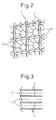
- the strip-shaped wall surfaces defined by the end surfaces of the partition walls 4 extend in the shape of a grid and cross each other to form a depression. Therefore, the end surface defined by the end surfaces of the partition walls 4 of the substrate 1, as shown in the sectional view of Fig. 3, has a convexo-concave shape with a bottom located at a tip T of the substantially regular rectangular pyramidal walls 5, 6 of the substrate 1 and a crest between the tips T.
- a pre-mold 10 having a honeycombed structure of a porous material such as cordierite or silicon nitride is formed first as shown in Fig. 4.
- the pre-mold 10 has a plurality of passages 2, 3 defined by a plurality of partition walls 4 and extending in parallel with each other.
- the passages 2, 3 have a square cross section.
- a jig 11 is pressed against the end surface of the pre-mold 10.
- the jig 11 has a plurality of protrusions 12 as shown in Figs. 4 and 5.
- the protrusions 12 each have the shape of a substantially regular rectangular pyramid and are aligned at predetermined intervals. Therefore, strip-shaped wall surfaces 13 extend between the protrusions 12. These strip-shaped wall surfaces 13 are concentrated at a corresponding area A where the bottom corners of the four adjacent protrusions 12 join each other.
- the strip-shaped wall surfaces 13 are assembled forming a hill toward a corresponding concentrated portion B.
- the jig 11 is pressed against the end surface of the pre-mold 10 in such a manner that the protrusions 12 enter passages adjacent to the passages to be closed, i.e. passages other than the passages to be closed.
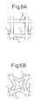
- the linearly extending end of each partition wall 4 is transformed by being bent at the central portion thereof toward the center axis C of the passage to be closed, as shown in Fig. 6B.
- the ends of the four partition walls 4 defining each passage to be closed are transformed toward each other so that the forward ends of the partition walls 4 are connected to each other.
- the jig 11 further continues to be pressed against the end surface of the pre-mold 10 and, thus, the ends of the partition walls 4 continue to be transformed toward the center axis C of the passage.
- the end surfaces of the partition walls 4 come into contact with the strip-shaped wall surfaces 13 of the jig 11.
- the end surfaces of the partition walls 4 are transformed, and are driven into the pre-mold 10 (i.e. the substrate 1) by the wall surface 13.
- the end surfaces of the partition walls are transformed into a depression having a deepest portion at the center axis C of the passage.
- the ends of the partition walls 4 are transformed toward the center axis of the passage, while at the same time transforming the end surface of the partition walls 4 into a depression having a deepest portion at the center axis C of the passage.
- the openings of predetermined passages are closed by the substantially regular rectangular pyramidal walls 5, 6.
- the passages can be positively closed up.
- the partition walls 21 defining the passages to be closed are transformed toward the center axis of the corresponding passages while being bent at the central portion thereof.
- the ends of the four partition walls 21 defining a corresponding passage to be closed are transformed toward each other so that the forward ends of the partition walls 21 are connected to each other.
- each partition wall 21 defining the passage to be closed is substantially equal throughout the forward ends of the partition walls 21, with the result that the forward ends of the partition walls 21 may fail to be sufficiently connected and undesirably form a hole at portions near the center axis of the passage.
- the amount by which the forward ends of the partition walls 4 defining the passage to be closed are transformed and are driven into the substrate 1 progressively increases toward the center axis C of the passage.
- the forward ends of the partition walls 4 are pushed into the substrate 1 to a greater degree, the nearer the center axis C of the passage.
- the forward ends of the partition walls 4 are connected sufficiently to each other.
- the ends of the partition walls defining each passage to be closed are transformed in such a manner that the particular ends come closer to each other.
- the forward ends of the partition walls are transformed to come still closer to each other and are connected to each other in such a manner that the transformed end surfaces of the partition walls are formed into a depression centered on the center axis of the passage.
- the ends of the partition walls defining the passage to be closed may be transformed to come closer to each other, followed by transforming the forward ends of the partition walls still closer to each other in such a manner that the end surfaces of the transformed partition walls are formed into a depression centered on the center axis of the passage, thereby connecting the forward ends of the partition walls to each other.
- the amount by which the partition wall ends are required to be transformed, to close up the opening of the passage to be closed can be calculated from the shape (depression in the embodiments described above) of the partition wall ends required to close up the same opening. The partition wall ends thus are transformed by this amount.
- the step of transforming the partition wall ends closer toward the center axis of the passage is called a first step
- the step of transforming the end surfaces of the transformed partition walls are transformed into a depression centered on the center axis of the passage is called a second step
- the partition wall ends are transformed by an amount smaller than the transformation amount calculated above, followed by the second step in which the partition wall ends are transformed by the remainder of the calculated transformation amount by which the same wall ends are left without being transformed in the first step.
- the total amount of transformation in the first and second steps may be larger than the calculated transformation amount.
- the partition wall ends are transformed by an amount smaller than the calculated transformation amount in the first step, followed by the second step in which the partition wall ends are further transformed by an amount larger than the remainder of the calculated transformation amount by which the particular partition walls are left without being transformed in the first step.
- the invention is also applicable to an exhaust gas purifying substrate fabricated from a pre-mold 10 having the configuration shown in Fig. 8, and to a method of fabricating such a substrate.
- the pre-mold 10 according to the second embodiment shown in Fig. 8 has a plurality of passages 2, 3 defined by a plurality of partition walls 4 and extending in parallel to each other.
- the passages 2, 3 have a regular triangular cross section.
- a jig 11, shown in Fig. 9 is used.
- the jig 11 has a plurality of protrusions 12 substantially in the shape of a truncated regular hexagonal pyramid.
- the protrusions 12 are arranged in alignment at predetermined spatial intervals. Therefore, a strip-shaped wall surface 13 extends between adjacent protrusions 12. These strip-shaped wall surfaces 13 join each other in an area A where the bottom corners of three adjacent protrusions 12 are concentrated. These strip-shaped wall surfaces 13 are concentrated in such a manner as to be protruded toward the concentrated portion B.
- the jig 11 is pressed against the end surface of the pre-mold 10 in such a way that a passage adjoining each passage to be closed, i.e. a passage other than to be closed, is entered by the corresponding protrusion 12.
- the ends of the partition walls 4 are transformed toward the center axis of the passage by the protrusions 12 while being bent at the central portion thereof. Specifically, the ends of the three partition walls 4 defining each passage are transformed to come closer to each other, so that the forward ends of the partition walls 4 are connected to each other.
- the jig 11 then continues to be pressed against the end surface of the pre-mold 10, and thus the ends of the partition walls 4 continue to be transformed toward the center axis of the passage.
- the end surfaces of the partition walls 4 come into contact with the strip-shaped wall surfaces 13 of the jig 11, whereby the end surfaces of the partition walls 4 are transformed and are driven into the pre-mold 10 (i.e. the substrate).
- the end surface of each partition wall 4 is transformed into a depression having a deepest portion at the center axis (tip T of a substantially regular hexagonal wall) of the passage.
- the openings of predetermined passages are closed up by the substantially regular hexagonal walls.
- the ratio of the amount required to transform the partition wall end toward the center axis of a given passage having a regular triangular cross section to close the particular passage relative to the length of one side of each passage, i.e. relative to the width of the partition walls defining the particular passage, is smaller than a similar ratio of the amount required to transform the partition wall end toward the center axis of the passage having a regular triangular cross section to close the same passage relative to the length of one side of each passage.
- the breakage of the partition wall ends during the transformation thereof is suppressed.
- the second embodiment therefore, as compared with the first embodiment, has the advantage of a smaller chance of the partition wall ends being broken during the transformation thereof.
- This invention is of course not limited to an exhaust gas purifying substrate fabricated from a pre-mold configured of passages having a square cross section or a regular triangular cross section and a method of fabrication thereof.
- the invention is also applicable to an exhaust gas purifying substrate fabricated from a pre-mold configured of passages having a cross section of a polygon such as a rectangle, triangle or hexagon and a method of fabrication thereof.
- the jig having substantially regular square pyramidal protrusions may alternatively have truncated and substantially regular hexagonal protrusions.
- a jig having truncated and substantially regular hexagonal protrusions may be replaced with a jig having substantially regular hexagonal protrusions with sharp tips.
- the forward ends of the partition walls are transformed to come close to each other and connected to each other without fail
Landscapes
- Engineering & Computer Science (AREA)
- Chemical & Material Sciences (AREA)
- Mechanical Engineering (AREA)
- Chemical Kinetics & Catalysis (AREA)
- General Engineering & Computer Science (AREA)
- Combustion & Propulsion (AREA)
- Organic Chemistry (AREA)
- Materials Engineering (AREA)
- Structural Engineering (AREA)
- Ceramic Engineering (AREA)
- Filtering Materials (AREA)
- Processes For Solid Components From Exhaust (AREA)
- Exhaust Gas After Treatment (AREA)
- Filtering Of Dispersed Particles In Gases (AREA)
- Catalysts (AREA)
Abstract
Description
- The present invention relates to a substrate used for purifying exhaust gas and a method of fabricating the substrate.
- A particulate filter for trapping fine particles in the exhaust gas emitted from the combustion chamber of the internal combustion engine is disclosed in Japanese Unexamined Patent Publication No. 8-508199. This filter has a plurality of passages defined by a plurality of partition walls of a porous material and extending in parallel with each other. One end opening of one of each adjacent two passages is closed, while the other end opening of the other of the adjacent two passages is closed. The exhaust gas that has flowed into a passage of the filter, therefore, flows into adjacent passages through the fine holes of the partition walls.
- In the filter described in the publication cited above, the selected openings of the passages are closed by transforming and connecting the end portions of the partition walls into the form of a rectangular pyramid. In closing the end openings of the passages of this filter, a honeycombed structure of a porous material and a jig having a plurality of protrusions are prepared, and the jig is pressed against the end surface of the honeycombed structure so that the protrusions alternately enter the passages of the honeycombed structure.
- In the case where the jig is pressed against the end surface of the honeycombed structure to close the openings of the passages by transforming the partition wall ends as described above, however, the partition wall ends may not be sufficiently connected and the openings of the passages may not be closed up completely. The object of this invention is to positively close up the passage openings of a substrate for purifying the exhaust gas.
- In order to solve the problem described above, according to a first aspect of the invention, there is provided a method of fabricating a substrate used for purifying the exhaust gas, comprising:
- the step of forming a pre-mold including a first end, a second end, a plurality of partition walls extending between the first end and the second end, and a plurality of passages defined by the plurality of the partition walls;
- the first transforming step for transforming the ends of the partition walls, at the first end of the pre-mold, defining one of each two adjacent passages in such a manner that the ends of the partition walls are collected toward the center of the corresponding passage and connected to each other; and
- the second transforming step for transforming the ends of the partition walls, at the first end of the pre-mold, in such a manner that the end surface of each of the partition walls at said first end of said pre-mold is depressed toward the center of the end surface.
- According to a second aspect of the invention, there is provided a method, in the first aspect of the invention, wherein the first transforming step and the second transforming step are executed at the same time.
- According to a third aspect of the invention, there is provided a method, in the first aspect of the invention, wherein the second transforming step is executed after the first transforming step.
- According to a fourth aspect of the invention, there is provided a method in the first aspect of the invention, wherein the amount of transformation of the partition wall ends in the first transforming step is smaller than the minimum amount required to close up a corresponding passage with the same partition wall ends, and the amount of transformation of the partition wall ends in the second transforming step is equal to the difference between the aforementioned minimum required amount and the transformation amount of the partition wall ends in the first transforming step.
- According to a fifth aspect of the invention, there is provided a method, in the first aspect of the invention, wherein the amount of transformation of the partition wall ends in the first transforming step is smaller than the minimum amount required to close up a corresponding passage with the same partition wall ends, and the amount of transformation of the partition wall ends in the second transforming step is larger than the difference between the aforementioned required minimum amount and the transformation amount of the partition wall ends in the first transforming step.
- According to a sixth aspect of the invention, there is provided a method, in the first aspect of the invention, wherein the cross section of the passages is a square and the partition wall ends closing the corresponding passages each form a portion in the shape of a substantially regular rectangular pyramid.
- According to a seventh aspect of the invention, there is provided a method in the first aspect of the invention, wherein the cross section of the passages is a regular triangle and the partition wall ends closing the corresponding passages each form a portion in the shape of a substantially regular hexagonal pyramid.
- According to an eighth aspect of the invention, there is provided a method, in the first aspect of the invention, wherein the pre-mold is formed of a porous material.
- According to a ninth aspect of the invention, there is provided a method, in the first aspect of the invention, further comprising the third transforming step for transforming the partition wall ends at the second end of the pre-mold defining the other of the two adjacent passages in such a manner that the partition wall ends are collected toward the center of the corresponding passage and connected to each other, and the fourth transforming step for transforming the partition wall ends at the second end of the pre-mold in such a manner that the end surfaces of the partition walls at the second end of the pre-mold are depressed toward the center of the end surface.
- According to a tenth aspect of the invention, there is provided a method, in the ninth aspect of the invention, wherein the first transforming step and the second transforming step are executed at the same time, and the third transforming step and the fourth transforming step are executed at the same time.
- According to an 11th aspect of the invention, there is provided a method, in the ninth aspect of the invention, wherein the second transforming step is executed after the first transforming step, and the fourth transforming step is executed after the third transforming step.
- According to a 12th aspect of the invention, there is provided a method in the ninth aspect of the invention, wherein the amount of transformation of the partition wall ends in the first transforming step is smaller than the minimum amount required to close up the passages with the partition wall ends, the amount of transformation of the partition wall ends in the second transforming step is equal to the difference between the required minimum amount and the transformation amount of the partition wall ends in the first transforming step, the amount of transformation of the partition wall ends in the third transforming step is smaller than the minimum amount required to close up the passages with the partition wall ends, and the amount of transformation of the partition wall ends in the fourth transforming step is equal to the difference between the required minimum amount and the transformation amount of the partition wall ends in the third transforming step.
- According to a 13th aspect of the invention, there is provided a method in the ninth aspect of the invention, wherein the amount of transformation of the partition wall ends in the first transforming step is smaller than the minimum amount required to close up the passages with the partition wall ends, the amount of transformation of the partition wall ends in the second transforming step is larger than the difference between the required minimum amount and the transformation amount of the partition wall ends in the first transforming step, the amount of transformation of the partition wall ends in the third transforming step is smaller than the minimum amount required to close up the passages with the partition wall ends, and the amount of transformation of the partition wall ends in the fourth transforming step is larger than the difference between the required minimum amount and the transformation amount of the partition wall ends in the third transforming step.
- Further, in order to solve the problem described above, according to a 14th aspect of the invention, there is provided a substrate used for purifying the exhaust gas, comprising a first end, a second end, a plurality of partition walls extending between the first end and the second end, and a plurality of passages defined by the plurality of the partition walls, wherein the ends of a plurality of the partition walls at the first end of the substrate defining one of each two adjacent passages are collected toward the center of a corresponding passage and connected with each other, the end surface of the partition wall ends at the first end of the substrate being depressed toward the center of the end surface, and wherein the ends of a plurality of the partition walls at the second end of the substrate defining the remaining one of the two adjacent passages are collected toward the center of the corresponding passage and connected with each other, the end surface of the partition walls at the second end of the substrate being depressed toward the center of the end surface.
- According to a 15th aspect of the invention, there is provided a substrate, in the 14th aspect of the invention, wherein the cross section of the passages is a square in shape and the partition wall ends closing the corresponding passages form a portion substantially in the shape of a regular rectangular pyramid.
- According to a 16th aspect of the invention, there is provided a substrate in the 14th aspect of the invention, wherein the cross section of the passages is a regular triangle in shape and the partition wall ends closing the corresponding passages form a portion substantially in the shape of a regular hexagonal pyramid.
- According to a 17th aspect of the invention, there is provided a substrate in the 14th aspect of the invention, wherein the substrate is formed of a porous material.
- The present invention may be more fully understood from the description of the preferred embodiments of the invention set forth below together with the accompanying drawings, in which:
- Fig. 1A is a diagram showing an end surface of a substrate according to this invention;
- Fig. 1B is a longitudinal sectional view of the substrate according to the invention shown in Fig. 1A;
- Fig 2 is a perspective view showing a part of the end surface of the substrate;
- Fig. 3 is a sectional view along the end surface of the partition walls of the substrate;
- Fig. 4 is a diagram for explaining a method of fabricating a substrate according to the invention;
- Fig. 5 is a perspective view showing a jig used in a method of fabricating a substrate according to the invention;
- Fig. 6A is a diagram showing the partition walls of the substrate not yet transformed;
- Fig. 6B is a diagram showing the partition walls of the substrate being transformed;
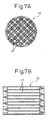
- Fig. 7A is a diagram showing an end surface of a substrate as compared with the substrate according to the invention;
- Fig. 7B is a longitudinal sectional view of the substrate shown in Fig. 7A;
- Fig. 8 is a diagram showing an end surface of a pre-mold used in another embodiment;
- Fig. 9 is a perspective view of a jig used in another embodiment; and
- Fig. 10 is a diagram showing an end surface of the substrate according to another embodiment.
- This invention will be explained with reference to the drawings. Fig. 1A shows an end surface of a substrate according to a first embodiment, and Fig. 1B is a longitudinal sectional view of the substrate shown in Fig. 1A. The substrate 1 has a honeycombed structure having a plurality of
passages passage partition walls 4. The substrate 1, i.e. thepartition walls 4 are formed of a porous material. The substrate 1 is arranged in an exhaust gas passage of the internal combustion engine, for example, and used to trap the fine particles in the exhaust gas emitted from the combustion chamber of the internal combustion engine. The substrate 1 can of course be used as a carrier to carry a catalyst for purifying a specified component of the exhaust gas emitted from the combustion chamber of the internal combustion engine. - In the substrate 1, the
passages pyramidal walls adjacent passages pyramidal walls passages 2 and further into theadjacent passages 3 through thepartition walls 4 as indicated by arrow in Fig. 1B. - The substantially regular rectangular
pyramidal walls passages passages 2, 3) at the ends of the fourpartition walls 4 defining thepassages pyramidal walls partition walls 4 toward the top T. As shown in Fig. 2, therefore, the strip-shaped wall surfaces defined by the end surfaces of thepartition walls 4 extend in the shape of a grid and cross each other to form a depression. Therefore, the end surface defined by the end surfaces of thepartition walls 4 of the substrate 1, as shown in the sectional view of Fig. 3, has a convexo-concave shape with a bottom located at a tip T of the substantially regular rectangularpyramidal walls - Next, a method of fabricating a substrate according to the invention will be explained. In the method of fabricating a substrate according to the invention, a pre-mold 10 having a honeycombed structure of a porous material such as cordierite or silicon nitride is formed first as shown in Fig. 4. The pre-mold 10 has a plurality of
passages partition walls 4 and extending in parallel with each other. Thepassages - As shown in Fig. 4, a
jig 11 is pressed against the end surface of the pre-mold 10. Thejig 11 has a plurality ofprotrusions 12 as shown in Figs. 4 and 5. Theprotrusions 12 each have the shape of a substantially regular rectangular pyramid and are aligned at predetermined intervals. Therefore, strip-shaped wall surfaces 13 extend between theprotrusions 12. These strip-shaped wall surfaces 13 are concentrated at a corresponding area A where the bottom corners of the fouradjacent protrusions 12 join each other. The strip-shaped wall surfaces 13 are assembled forming a hill toward a corresponding concentrated portion B. - According to this invention, the
jig 11 is pressed against the end surface of the pre-mold 10 in such a manner that theprotrusions 12 enter passages adjacent to the passages to be closed, i.e. passages other than the passages to be closed. Once thejig 11 begins to be pressed against the end surface of the pre-mold 10, as shown in Fig. 6A, the linearly extending end of eachpartition wall 4 is transformed by being bent at the central portion thereof toward the center axis C of the passage to be closed, as shown in Fig. 6B. Specifically, the ends of the fourpartition walls 4 defining each passage to be closed are transformed toward each other so that the forward ends of thepartition walls 4 are connected to each other. - The
jig 11 further continues to be pressed against the end surface of the pre-mold 10 and, thus, the ends of thepartition walls 4 continue to be transformed toward the center axis C of the passage. At the same time, the end surfaces of thepartition walls 4 come into contact with the strip-shaped wall surfaces 13 of thejig 11. Thus, the end surfaces of thepartition walls 4 are transformed, and are driven into the pre-mold 10 (i.e. the substrate 1) by thewall surface 13. As a result, the end surfaces of the partition walls are transformed into a depression having a deepest portion at the center axis C of the passage. More specifically, according to this invention, the ends of thepartition walls 4 are transformed toward the center axis of the passage, while at the same time transforming the end surface of thepartition walls 4 into a depression having a deepest portion at the center axis C of the passage. In this way, the openings of predetermined passages are closed by the substantially regular rectangularpyramidal walls - According to this invention, as compared with the
substrate 20 configured as shown in Figs. 7A and 7B, the passages can be positively closed up. This fact will be explained. In the substrate shown in Figs. 7A and 7B, thepartition walls 21 defining the passages to be closed are transformed toward the center axis of the corresponding passages while being bent at the central portion thereof. Specifically, the ends of the fourpartition walls 21 defining a corresponding passage to be closed are transformed toward each other so that the forward ends of thepartition walls 21 are connected to each other. In the process, however, the amount by which the forward ends of eachpartition wall 21 defining the passage to be closed are transformed and are driven into the substrate is substantially equal throughout the forward ends of thepartition walls 21, with the result that the forward ends of thepartition walls 21 may fail to be sufficiently connected and undesirably form a hole at portions near the center axis of the passage. - According to the invention, in contrast, the amount by which the forward ends of the
partition walls 4 defining the passage to be closed are transformed and are driven into the substrate 1 progressively increases toward the center axis C of the passage. As a result, the forward ends of thepartition walls 4 are pushed into the substrate 1 to a greater degree, the nearer the center axis C of the passage. Thus, the forward ends of thepartition walls 4 are connected sufficiently to each other. - In this invention, as described above, the ends of the partition walls defining each passage to be closed are transformed in such a manner that the particular ends come closer to each other. At the same time, the forward ends of the partition walls are transformed to come still closer to each other and are connected to each other in such a manner that the transformed end surfaces of the partition walls are formed into a depression centered on the center axis of the passage. As an alternative, the ends of the partition walls defining the passage to be closed may be transformed to come closer to each other, followed by transforming the forward ends of the partition walls still closer to each other in such a manner that the end surfaces of the transformed partition walls are formed into a depression centered on the center axis of the passage, thereby connecting the forward ends of the partition walls to each other.
- Also, according to the invention, the amount by which the partition wall ends are required to be transformed, to close up the opening of the passage to be closed, can be calculated from the shape (depression in the embodiments described above) of the partition wall ends required to close up the same opening. The partition wall ends thus are transformed by this amount. Specifically, if the step of transforming the partition wall ends closer toward the center axis of the passage is called a first step, and the step of transforming the end surfaces of the transformed partition walls are transformed into a depression centered on the center axis of the passage is called a second step them, in the first step, the partition wall ends are transformed by an amount smaller than the transformation amount calculated above, followed by the second step in which the partition wall ends are transformed by the remainder of the calculated transformation amount by which the same wall ends are left without being transformed in the first step.
- The total amount of transformation in the first and second steps may be larger than the calculated transformation amount. In such a case, the partition wall ends are transformed by an amount smaller than the calculated transformation amount in the first step, followed by the second step in which the partition wall ends are further transformed by an amount larger than the remainder of the calculated transformation amount by which the particular partition walls are left without being transformed in the first step. By doing so, the forward ends of the partition walls are transformed and crushed into the same shape.
- The invention is also applicable to an exhaust gas purifying substrate fabricated from a pre-mold 10 having the configuration shown in Fig. 8, and to a method of fabricating such a substrate. Specifically, the pre-mold 10 according to the second embodiment shown in Fig. 8 has a plurality of
passages partition walls 4 and extending in parallel to each other. Thepassages jig 11, shown in Fig. 9, is used. Thejig 11 has a plurality ofprotrusions 12 substantially in the shape of a truncated regular hexagonal pyramid. Theprotrusions 12 are arranged in alignment at predetermined spatial intervals. Therefore, a strip-shapedwall surface 13 extends betweenadjacent protrusions 12. These strip-shaped wall surfaces 13 join each other in an area A where the bottom corners of threeadjacent protrusions 12 are concentrated. These strip-shaped wall surfaces 13 are concentrated in such a manner as to be protruded toward the concentrated portion B. - The
jig 11 is pressed against the end surface of the pre-mold 10 in such a way that a passage adjoining each passage to be closed, i.e. a passage other than to be closed, is entered by the correspondingprotrusion 12. Once thejig 11 begins to be pressed against the end surface of the pre-mold 10, the ends of thepartition walls 4 are transformed toward the center axis of the passage by theprotrusions 12 while being bent at the central portion thereof. Specifically, the ends of the threepartition walls 4 defining each passage are transformed to come closer to each other, so that the forward ends of thepartition walls 4 are connected to each other. - The
jig 11 then continues to be pressed against the end surface of the pre-mold 10, and thus the ends of thepartition walls 4 continue to be transformed toward the center axis of the passage. At the same time, the end surfaces of thepartition walls 4 come into contact with the strip-shaped wall surfaces 13 of thejig 11, whereby the end surfaces of thepartition walls 4 are transformed and are driven into the pre-mold 10 (i.e. the substrate). In this way, the end surface of eachpartition wall 4 is transformed into a depression having a deepest portion at the center axis (tip T of a substantially regular hexagonal wall) of the passage. Thus, the openings of predetermined passages are closed up by the substantially regular hexagonal walls. - The matters explained regarding the first embodiment can be applied also to the second embodiment. Also, the ratio of the amount required to transform the partition wall end toward the center axis of a given passage having a regular triangular cross section to close the particular passage relative to the length of one side of each passage, i.e. relative to the width of the partition walls defining the particular passage, is smaller than a similar ratio of the amount required to transform the partition wall end toward the center axis of the passage having a regular triangular cross section to close the same passage relative to the length of one side of each passage. In this case, the breakage of the partition wall ends during the transformation thereof is suppressed. The second embodiment, therefore, as compared with the first embodiment, has the advantage of a smaller chance of the partition wall ends being broken during the transformation thereof.
- This invention is of course not limited to an exhaust gas purifying substrate fabricated from a pre-mold configured of passages having a square cross section or a regular triangular cross section and a method of fabrication thereof. Alternatively, the invention is also applicable to an exhaust gas purifying substrate fabricated from a pre-mold configured of passages having a cross section of a polygon such as a rectangle, triangle or hexagon and a method of fabrication thereof. Also in the embodiments described above, the jig having substantially regular square pyramidal protrusions may alternatively have truncated and substantially regular hexagonal protrusions. Further, a jig having truncated and substantially regular hexagonal protrusions may be replaced with a jig having substantially regular hexagonal protrusions with sharp tips.
- According to this invention, the forward ends of the partition walls are transformed to come close to each other and connected to each other without fail
- While the invention has been described by reference to specific embodiments chosen for purposes of illustration, it should be apparent that numerous modifications could be made thereto by those skilled in the art without departing from the basic concept and scope of the invention.
Claims (17)
- A method of fabricating a substrate used for purifying the exhaust gas, comprising:the step of forming a pre-mold including a first end, a second end, a plurality of partition walls extending between the first end and the second end, and a plurality of passages defined by the plurality of the partition walls;the first transforming step for transforming the ends of the partition walls at the first end of the pre-mold defining one of each two adjacent passages in such a manner that the ends of the partition walls are collected toward the center of the corresponding passage and connected to each other; andthe second transforming step for transforming the ends of the partition walls at the first end of the pre-mold in such a manner that the end surface of each of the partition walls at said first end of said pre-mold is depressed toward the center of the end surface.
- A method according to claim 1, wherein the first transforming step and the second transforming step are executed at the same time.
- A method according to claim 1, wherein the second transforming step is executed after the first transforming step.
- A method according to claim 1, wherein the amount of transformation of the partition wall ends in the first transforming step is smaller than the minimum amount required to close up a corresponding passage with the same partition wall ends, and the amount of transformation of the partition wall ends in the second transforming step is equal to the difference between said minimum required amount and the transformation amount of the partition wall ends in the first transforming step.
- A method according to claim 1, wherein the amount of transformation of the partition wall ends in the first transforming step is smaller than the minimum amount required to close up a corresponding passage with the same partition wall ends, and the amount of transformation of the partition wall ends in the second transforming step is larger than the difference between said required minimum amount and the transformation amount of the partition wall ends in the first transforming step.
- A method according to claim 1, wherein the cross section of the passages is a square and the partition wall ends closing the corresponding passages each form a portion in the shape of a substantially regular rectangular pyramid.
- A method according to claim 1, wherein the cross section of the passages is a regular triangle and the partition wall ends closing the corresponding passages each form a portion in the shape of a substantially regular hexagonal pyramid.
- A method according to claim 1, wherein the pre-mold is formed of a porous material.
- A method according to claim 1, further comprising the third transforming step for transforming the partition wall ends at the second end of the pre-mold defining the other of the two adjacent passages in such a manner that the partition wall ends are collected toward the center of the corresponding passage and connected to each other, and the fourth transforming step for transforming the partition wall ends at the second end of the pre-mold in such a manner that the end surfaces of the partition walls at the second end of the pre-mold are depressed toward the center of the end surface.
- A method according to claim 9, wherein the first transforming step and the second transforming step are executed at the same time, and the third transforming step and the fourth transforming step are executed at the same time.
- A method according to claim 9, wherein the second transforming step is executed after the first transforming step, and the fourth transforming step is executed after the third transforming step.
- A method according to claim 9, wherein the amount of transformation of the partition wall ends in the first transforming step is smaller than the minimum amount required to close up the passages with the partition wall ends, the amount of transformation of the partition wall ends in the second transforming step is equal to the difference between the required minimum amount and the transformation amount of the partition wall ends in the first transforming step, the amount of transformation of the partition wall ends in the third transforming step is smaller than the minimum amount required to close up the passages with the partition wall ends, and the amount of transformation of the partition wall ends in the fourth transforming step is equal to the difference between the required minimum amount and the transformation amount of the partition wall ends in the third transforming step.
- A method according to claim 9, wherein the amount of transformation of the partition wall ends in the first transforming step is smaller than the minimum amount required to close up the passages with the partition wall ends, the amount of transformation of the partition wall ends in the second transforming step is larger than the difference between the required minimum amount and the transformation amount of the partition wall ends in the first transforming step, the amount of transformation of the partition wall ends in the third transforming step is smaller than the minimum amount required to close up the passages with the partition wall ends, and the amount of transformation of the partition wall ends in the fourth transforming step is larger than the difference between the required minimum amount and the transformation amount of the partition wall ends in the third transforming step.
- A substrate used for purifying the exhaust gas, comprising:a first end;a second end;a plurality of partition walls extending between the first end and the second end; anda plurality of passages defined by the plurality of the partition walls;wherein the ends of a plurality of the partition walls at the first end of the substrate defining one of each two adjacent passages are collected toward the center of a corresponding passage and connected with each other, the end surface of the partition wall ends at the first end of the substrate being depressed toward the center of the end surface; and
wherein the ends of a plurality of the partition walls at the second end of the substrate defining the remaining one of the two adjacent passages are collected toward the center of the corresponding passage and connected with each other, the end surface of the partition walls at the second end of the substrate being depressed toward the center of the end surface. - A substrate according to claim 14, wherein the cross section of the passages is a square in shape and the partition wall ends closing the corresponding passages form a portion substantially in the shape of a regular rectangular pyramid.
- A substrate according to claim 14, wherein the cross section of the passages is a regular triangle in shape and the partition wall ends closing the corresponding passages form a portion substantially in the shape of a regular hexagonal pyramid.
- A substrate according to claim 14, wherein the substrate is formed of a porous material.
Applications Claiming Priority (2)
| Application Number | Priority Date | Filing Date | Title |
|---|---|---|---|
| JP2002279517A JP4032902B2 (en) | 2002-09-25 | 2002-09-25 | Substrate for exhaust purification and method for manufacturing the same |
| JP2002279517 | 2002-09-25 |
Publications (3)
| Publication Number | Publication Date |
|---|---|
| EP1403477A2 true EP1403477A2 (en) | 2004-03-31 |
| EP1403477A3 EP1403477A3 (en) | 2008-09-24 |
| EP1403477B1 EP1403477B1 (en) | 2011-07-27 |
Family
ID=31973283
Family Applications (1)
| Application Number | Title | Priority Date | Filing Date |
|---|---|---|---|
| EP03021539A Expired - Lifetime EP1403477B1 (en) | 2002-09-25 | 2003-09-24 | Substrate used for exhaust gas purification and method of fabrication thereof |
Country Status (5)
| Country | Link |
|---|---|
| US (1) | US6972045B2 (en) |
| EP (1) | EP1403477B1 (en) |
| JP (1) | JP4032902B2 (en) |
| KR (2) | KR100606617B1 (en) |
| CN (1) | CN1304738C (en) |
Cited By (3)
| Publication number | Priority date | Publication date | Assignee | Title |
|---|---|---|---|---|
| WO2005097446A1 (en) * | 2004-04-07 | 2005-10-20 | Liqtech A/S | Method for forming organic bonded bodies using ultrasonic energy |
| WO2007145548A1 (en) * | 2006-06-13 | 2007-12-21 | Volvo Lastvagnar Ab | Diesel catalyst system |
| EP3303258A4 (en) * | 2015-05-29 | 2018-12-26 | Corning Incorporated | Honeycomb filter plugging and apparatus for honeycomb filter plugging |
Families Citing this family (15)
| Publication number | Priority date | Publication date | Assignee | Title |
|---|---|---|---|---|
| JP3719232B2 (en) * | 2002-06-18 | 2005-11-24 | トヨタ自動車株式会社 | Particulate filter for internal combustion engine |
| JP3945452B2 (en) * | 2003-05-30 | 2007-07-18 | 株式会社デンソー | Manufacturing method of exhaust gas purification filter |
| JP4946033B2 (en) * | 2005-03-01 | 2012-06-06 | 株式会社デンソー | Manufacturing method of exhaust gas purification filter |
| EP2213852A4 (en) * | 2007-10-16 | 2014-12-17 | Yanmar Co Ltd | Black smoke purification device |
| KR200456775Y1 (en) | 2010-02-25 | 2011-11-21 | 주식회사 원일공기정화 | Fluid Droplet Filter Using Impingement and Vortex |
| WO2014061496A1 (en) * | 2012-10-15 | 2014-04-24 | 住友化学株式会社 | Production method for honeycomb structure |
| MX2015004706A (en) * | 2012-10-15 | 2015-07-23 | Sumitomo Chemical Co | Method for producing honeycomb structure and sealing jig for green honeycomb moulded article. |
| WO2014103839A1 (en) * | 2012-12-27 | 2014-07-03 | 住友化学株式会社 | Method for manufacturing honeycomb structure |
| JP6140554B2 (en) * | 2013-06-28 | 2017-05-31 | 住友化学株式会社 | Manufacturing method of honeycomb structure |
| JP2015009442A (en) * | 2013-06-28 | 2015-01-19 | 住友化学株式会社 | Method for producing honeycomb structure, and tool for sealing green honeycomb molding |
| USD772389S1 (en) * | 2013-07-24 | 2016-11-22 | Ngk Insulators, Ltd. | Filter for removing particle matter |
| JP6596413B2 (en) * | 2014-03-03 | 2019-10-23 | イビデン株式会社 | Honeycomb filter and method for manufacturing honeycomb filter |
| USD860748S1 (en) * | 2017-10-31 | 2019-09-24 | Lake Country Manufacturing, Inc. | Buffing pad with collapsed cell structure |
| JP2020059638A (en) * | 2018-10-12 | 2020-04-16 | イビデン株式会社 | Honeycomb structure |
| JP7125823B2 (en) * | 2018-10-12 | 2022-08-25 | イビデン株式会社 | honeycomb structure |
Family Cites Families (14)
| Publication number | Priority date | Publication date | Assignee | Title |
|---|---|---|---|---|
| JPS61183182A (en) * | 1985-02-11 | 1986-08-15 | 株式会社デンソー | Porous ceramic structure |
| DK40293D0 (en) * | 1993-04-05 | 1993-04-05 | Per Stobbe | METHOD OF PREPARING A FILTER BODY |
| DE4439685A1 (en) * | 1994-11-07 | 1996-05-09 | Emitec Emissionstechnologie | Method and device for producing a honeycomb body, in particular a catalyst carrier body, with a housing |
| WO1996023134A1 (en) * | 1995-01-24 | 1996-08-01 | Axel Hartenstein | Device for removing substances in gas and vapour form in a stream of exhaust air |
| JPH0949421A (en) * | 1995-05-30 | 1997-02-18 | Sumitomo Electric Ind Ltd | Particulate trap for diesel engine |
| JP4222588B2 (en) * | 2000-11-24 | 2009-02-12 | 日本碍子株式会社 | Honeycomb filter and manufacturing method thereof |
| CN1285829C (en) * | 2001-08-08 | 2006-11-22 | 丰田自动车株式会社 | An exhaust gas purification device |
| JP3685106B2 (en) | 2001-08-08 | 2005-08-17 | トヨタ自動車株式会社 | Exhaust purification device |
| US7141088B2 (en) * | 2001-08-08 | 2006-11-28 | Toyota Jidosha Kabushiki Kaisha | Exhaust gas purifying apparatus |
| JP4186530B2 (en) * | 2001-08-28 | 2008-11-26 | 株式会社デンソー | Manufacturing method of exhaust gas purification filter |
| JP3719232B2 (en) * | 2002-06-18 | 2005-11-24 | トヨタ自動車株式会社 | Particulate filter for internal combustion engine |
| JP3873924B2 (en) * | 2002-06-24 | 2007-01-31 | 株式会社デンソー | Exhaust gas purification filter and manufacturing method thereof |
| JP2004321848A (en) * | 2003-04-21 | 2004-11-18 | Ngk Insulators Ltd | Honeycomb structure and its manufacturing method |
| JP2004324575A (en) * | 2003-04-25 | 2004-11-18 | Toyota Motor Corp | Manufacturing method of particulate filter |
-
2002
- 2002-09-25 JP JP2002279517A patent/JP4032902B2/en not_active Expired - Fee Related
-
2003
- 2003-07-21 KR KR1020030049795A patent/KR100606617B1/en not_active Expired - Fee Related
- 2003-09-08 US US10/656,205 patent/US6972045B2/en not_active Expired - Lifetime
- 2003-09-24 EP EP03021539A patent/EP1403477B1/en not_active Expired - Lifetime
- 2003-09-25 CN CNB031598196A patent/CN1304738C/en not_active Expired - Fee Related
-
2006
- 2006-02-28 KR KR1020060019458A patent/KR100654113B1/en not_active Expired - Fee Related
Cited By (5)
| Publication number | Priority date | Publication date | Assignee | Title |
|---|---|---|---|---|
| WO2005097446A1 (en) * | 2004-04-07 | 2005-10-20 | Liqtech A/S | Method for forming organic bonded bodies using ultrasonic energy |
| WO2007145548A1 (en) * | 2006-06-13 | 2007-12-21 | Volvo Lastvagnar Ab | Diesel catalyst system |
| US8601796B2 (en) | 2006-06-13 | 2013-12-10 | Volvo Lastvagnar Ab | Diesel catalyst system |
| EP3303258A4 (en) * | 2015-05-29 | 2018-12-26 | Corning Incorporated | Honeycomb filter plugging and apparatus for honeycomb filter plugging |
| US10940420B2 (en) | 2015-05-29 | 2021-03-09 | Corning Incorporated | Honeycomb filter plugging and apparatus for honeycomb filter plugging |
Also Published As
| Publication number | Publication date |
|---|---|
| KR100654113B1 (en) | 2006-12-05 |
| KR20040027299A (en) | 2004-04-01 |
| US6972045B2 (en) | 2005-12-06 |
| CN1497138A (en) | 2004-05-19 |
| KR100606617B1 (en) | 2006-07-28 |
| EP1403477B1 (en) | 2011-07-27 |
| JP2004116369A (en) | 2004-04-15 |
| JP4032902B2 (en) | 2008-01-16 |
| US20040055264A1 (en) | 2004-03-25 |
| EP1403477A3 (en) | 2008-09-24 |
| CN1304738C (en) | 2007-03-14 |
| KR20060026932A (en) | 2006-03-24 |
Similar Documents
| Publication | Publication Date | Title |
|---|---|---|
| US6972045B2 (en) | Substrate used for exhaust gas purification and method of fabrication thereof | |
| EP1231363B1 (en) | Honeycomb particulate filter structure constituted by main and sub honeycomb structures | |
| US7527666B2 (en) | Honeycomb body with fissured end sides | |
| JP5460811B2 (en) | Modular gasket | |
| US7905939B2 (en) | Block for filtering particles contained in exhaust gases of an internal combustion engine | |
| US8007556B2 (en) | Block for filtering particles contained in exhaust gases of an internal combustion engine | |
| US7871576B2 (en) | Metal foil having different indentations and assembly, honeycomb body and exhaust gas treatment device having a metal foil | |
| RU2493384C2 (en) | Cellular element with zones of resilience | |
| JP2006035216A (en) | Filtering element for particulate trap | |
| EP1374971A1 (en) | Particulate filter for an internal combustion engine and method for producing the same | |
| JP4178871B2 (en) | Manufacturing method of exhaust purification material substrate | |
| JP2002317618A (en) | Exhaust gas purification device and method of manufacturing the same | |
| JP4110897B2 (en) | Substrate module and manufacturing method thereof | |
| JP2004322051A (en) | Method for producing base material for particulate filter | |
| EP3165734B1 (en) | Muffler integrated type gasoline engine particulate filter | |
| RU2719371C1 (en) | Catalyst structure | |
| KR20260014363A (en) | Filter | |
| WO2019022088A1 (en) | Honeycomb structure and method for producing honeycomb structure | |
| CN112922704A (en) | Honeycomb structure | |
| KR20040037724A (en) | Particulate trap | |
| JPH1182004A (en) | Exhaust gas purification device for internal combustion engine | |
| JPH04269316A (en) | Exhaust filter for internal combustion engine |
Legal Events
| Date | Code | Title | Description |
|---|---|---|---|
| PUAI | Public reference made under article 153(3) epc to a published international application that has entered the european phase |
Free format text: ORIGINAL CODE: 0009012 |
|
| 17P | Request for examination filed |
Effective date: 20030924 |
|
| AK | Designated contracting states |
Kind code of ref document: A2 Designated state(s): AT BE BG CH CY CZ DE DK EE ES FI FR GB GR HU IE IT LI LU MC NL PT RO SE SI SK TR |
|
| AX | Request for extension of the european patent |
Extension state: AL LT LV MK |
|
| PUAL | Search report despatched |
Free format text: ORIGINAL CODE: 0009013 |
|
| AK | Designated contracting states |
Kind code of ref document: A3 Designated state(s): AT BE BG CH CY CZ DE DK EE ES FI FR GB GR HU IE IT LI LU MC NL PT RO SE SI SK TR |
|
| AX | Request for extension of the european patent |
Extension state: AL LT LV MK |
|
| 17Q | First examination report despatched |
Effective date: 20081230 |
|
| AKX | Designation fees paid |
Designated state(s): DE FR IT |
|
| GRAP | Despatch of communication of intention to grant a patent |
Free format text: ORIGINAL CODE: EPIDOSNIGR1 |
|
| RIC1 | Information provided on ipc code assigned before grant |
Ipc: F01N 3/035 20060101ALI20110107BHEP Ipc: B28B 11/00 20060101AFI20110107BHEP Ipc: B01J 35/04 20060101ALI20110107BHEP Ipc: F01N 3/022 20060101ALI20110107BHEP |
|
| GRAS | Grant fee paid |
Free format text: ORIGINAL CODE: EPIDOSNIGR3 |
|
| GRAA | (expected) grant |
Free format text: ORIGINAL CODE: 0009210 |
|
| AK | Designated contracting states |
Kind code of ref document: B1 Designated state(s): DE FR IT |
|
| REG | Reference to a national code |
Ref country code: DE Ref legal event code: R096 Ref document number: 60337787 Country of ref document: DE Effective date: 20110915 |
|
| PLBE | No opposition filed within time limit |
Free format text: ORIGINAL CODE: 0009261 |
|
| STAA | Information on the status of an ep patent application or granted ep patent |
Free format text: STATUS: NO OPPOSITION FILED WITHIN TIME LIMIT |
|
| 26N | No opposition filed |
Effective date: 20120502 |
|
| REG | Reference to a national code |
Ref country code: DE Ref legal event code: R097 Ref document number: 60337787 Country of ref document: DE Effective date: 20120502 |
|
| REG | Reference to a national code |
Ref country code: DE Ref legal event code: R084 Ref document number: 60337787 Country of ref document: DE Effective date: 20130614 |
|
| REG | Reference to a national code |
Ref country code: FR Ref legal event code: PLFP Year of fee payment: 14 |
|
| REG | Reference to a national code |
Ref country code: FR Ref legal event code: PLFP Year of fee payment: 15 |
|
| REG | Reference to a national code |
Ref country code: FR Ref legal event code: PLFP Year of fee payment: 16 |
|
| PGFP | Annual fee paid to national office [announced via postgrant information from national office to epo] |
Ref country code: FR Payment date: 20180813 Year of fee payment: 16 Ref country code: DE Payment date: 20180911 Year of fee payment: 16 Ref country code: IT Payment date: 20180919 Year of fee payment: 16 |
|
| REG | Reference to a national code |
Ref country code: DE Ref legal event code: R119 Ref document number: 60337787 Country of ref document: DE |
|
| PG25 | Lapsed in a contracting state [announced via postgrant information from national office to epo] |
Ref country code: DE Free format text: LAPSE BECAUSE OF NON-PAYMENT OF DUE FEES Effective date: 20200401 |
|
| PG25 | Lapsed in a contracting state [announced via postgrant information from national office to epo] |
Ref country code: IT Free format text: LAPSE BECAUSE OF NON-PAYMENT OF DUE FEES Effective date: 20190924 |
|
| PG25 | Lapsed in a contracting state [announced via postgrant information from national office to epo] |
Ref country code: FR Free format text: LAPSE BECAUSE OF NON-PAYMENT OF DUE FEES Effective date: 20190930 |