EP1403199A2 - Sheet feeder for a sheet handling machine - Google Patents
Sheet feeder for a sheet handling machine Download PDFInfo
- Publication number
- EP1403199A2 EP1403199A2 EP03020540A EP03020540A EP1403199A2 EP 1403199 A2 EP1403199 A2 EP 1403199A2 EP 03020540 A EP03020540 A EP 03020540A EP 03020540 A EP03020540 A EP 03020540A EP 1403199 A2 EP1403199 A2 EP 1403199A2
- Authority
- EP
- European Patent Office
- Prior art keywords
- sheet
- ports
- sheet feeder
- plate
- port plate
- Prior art date
- Legal status (The legal status is an assumption and is not a legal conclusion. Google has not performed a legal analysis and makes no representation as to the accuracy of the status listed.)
- Granted
Links
Images




Classifications
-
- B—PERFORMING OPERATIONS; TRANSPORTING
- B65—CONVEYING; PACKING; STORING; HANDLING THIN OR FILAMENTARY MATERIAL
- B65H—HANDLING THIN OR FILAMENTARY MATERIAL, e.g. SHEETS, WEBS, CABLES
- B65H3/00—Separating articles from piles
- B65H3/08—Separating articles from piles using pneumatic force
- B65H3/12—Suction bands, belts, or tables moving relatively to the pile
- B65H3/124—Suction bands or belts
- B65H3/126—Suction bands or belts separating from the bottom of pile
-
- B—PERFORMING OPERATIONS; TRANSPORTING
- B65—CONVEYING; PACKING; STORING; HANDLING THIN OR FILAMENTARY MATERIAL
- B65H—HANDLING THIN OR FILAMENTARY MATERIAL, e.g. SHEETS, WEBS, CABLES
- B65H3/00—Separating articles from piles
- B65H3/08—Separating articles from piles using pneumatic force
- B65H3/12—Suction bands, belts, or tables moving relatively to the pile
- B65H3/124—Suction bands or belts
-
- B—PERFORMING OPERATIONS; TRANSPORTING
- B65—CONVEYING; PACKING; STORING; HANDLING THIN OR FILAMENTARY MATERIAL
- B65H—HANDLING THIN OR FILAMENTARY MATERIAL, e.g. SHEETS, WEBS, CABLES
- B65H2406/00—Means using fluid
- B65H2406/30—Suction means
- B65H2406/32—Suction belts
- B65H2406/322—Suction distributing means
Definitions
- the present invention relates to sheet feeding devices for sheet handling machines and in one of its aspects relates to vacuum-assisted, sheet feeder for a sheet handling device, e.g. a copier, printer, etc., having a means for controlling the air flow into vacuum plenum to alleviate misfeeds.
- a sheet handling device e.g. a copier, printer, etc.
- a critical consideration in most sheet handling machines is the ability to rapidly feed individual documents through the machine, one at a time.
- reproducing machines such as copiers, printers, and the like must include sheet feeding devices that are capable of rapidly and reliably feeding the individual sheets of a receiver medium (e.g. paper) through complex travel paths within the machine.
- a sheet-feeding device i.e. sheet feeder
- it must be capable of operating at high transport speeds with only a minimum of downtime due to misfeeds or multifeeds (hereinafter collectively referred to as "misfeeds").
- Sheet feeders are typically of two types; friction feeders and vacuum feeders.
- Friction feeders have been proven reliable for feeding individual sheets in many applications but, unfortunately, are susceptible to significant misfeeds when subjected to the harsher conditions normally found in higher speed copiers and printers.
- Vacuum feeders are more reliable for high-speed applications but require more precise control in reducing the number of misfeeds.
- one or more perforated belts move in a closed loop over a ported plate which, in turn, is in communication with a vacuum plenum.
- a vacuum plenum acts through the aligned holes to attract and hold an individual sheet (i.e. the bottommost sheet of the stack, if the feeder is a "bottom feed” or the topmost sheet, if the feeder is a "top feed”, hereinafter referred to as "acquired sheet") against the moving belts.
- a surface within the respective tray or hopper, which holds the stack of individual sheets, is configured (i.e. corrugated) to aid in separating the acquired sheet from the stack.
- a positive air stream is directed onto the front of the stack to further aid in separating the acquired sheet from the sheets remaining in the tray.
- the ports in the vacuum plate are configured so that the flow of air into the plenum is restricted near the lead edge of the stack in the tray. That is, the ports adjacent the lead edge of the stack are made smaller than the other ports in the vacuum plate in order to minimize the air flow through the ports near the lead edge of the stack that may align with a hole or the like in the sheet and thereby reduce the attractive force on the sheets as they are acquired and moved by the belts.
- the present invention provides a sheet feeder for use with a sheet-handling machine such as a copier, printer, or the like.
- the feeder has a tray, which is adapted to receive a stack of sheets of a copy medium (e.g. paper). The sheets are stacked in the tray and then are fed, one at a time, from the tray into the sheet-handling machine, as needed.
- a copy medium e.g. paper
- the sheet feeder of the present invention is comprised of a platform for stacking the sheets thereon.
- a feed head assembly is positioned adjacent the front or lead side of the platform and is adapted to acquire an individual sheet from the stack and feed it off of the front edge of the platform.
- the feed head assembly is comprised of a vacuum plenum, which is positioned towards the front of the platform.
- a port plate which closes the plenum, is substantially aligned with the front of the platform and is substantially parallel to the stack of sheets on the platform.
- the port plate has a plurality of ports through which air can flow into the plenum to thereby establish a vacuum at the ports.
- These ports are preferably positioned in two sets wherein the ports in the first set, i.e. those nearest the front of the port plate, are smaller than the ports in the second set which, in turn, lies between the back of the port plate and the first set of ports.
- a means is provided within the plenum to restrict the airflow through the first set of ports to reduce the possibility of acquiring a second sheet when the desired sheet is acquired.
- At least one belt having openings therethrough is mounted for movement through a closed loop around the vacuum plenum and across the port plate so that when openings in the belts align with any of the ports in the port plate, air will flow therethrough into the vacuum plenum to create a vacuum which, in turn, acquires individual sheet from the stack and tacks it against the belt. Movement of the belt then removes the acquired sheet from the stack and feeds it off the platform.
- the means for restricting the flow of air through the first set of ports is preferably comprised of an intermediate plate positioned within the vacuum plenum.
- the intermediate plate has a restrictive passage (e.g. a tortuous passage) in fluid communication with the first set of ports in the port plate.
- a cap plate abuts the intermediate plate and has one or more openings therein which communicate with the restrictive passage through the intermediate plate.
- the possibility of acquiring second sheet is alleviated, especially in copying operations where sheets are used which have pre-punched holes in the margin (i.e. lead edge) thereof.
- FIG. 1 is a schematic view of an electrophotographic apparatus (e.g. duplex copier/printer machine) in which the present invention may be incorporated;
- an electrophotographic apparatus e.g. duplex copier/printer machine
- FIG. 2 is a perspective view of a bottom-feed, sheet feeder (i.e. duplex tray), which includes the present invention
- FIG. 3 is an enlarged, side elevational view, partly in section, of the bottom-feed, sheet feeder of FIG. 2;
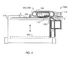
- FIG. 4 is a side elevation view, partly in section, of a top-feed, sheet feeder which includes the present invention
- FIG. 5 is a plan view of a sheet feeder, similar to that of FIGS. 2-4, with portions removed to facilitate viewing, showing a prior art configuration of the ports associated with the vacuum plenum of the feeder;
- FIG. 5A is a top plan view of a sheet feeder, similar to FIG. 4, showing the configuration of the ports associated with the vacuum plenum in accordance with the present invention
- FIG. 6 is an enlarged top plan view of portion of the port plate of the present invention.
- FIG. 7 is an exploded view of the principle components of the sheet feeder of the present invention.
- FIG. 1 schematically illustrates a typical document handling machine 10 (e.g. duplex copier, duplicator, printer, etc.) which can utilize the "top-feed", sheet feeder and/or the "bottom-feed”, sheet feeder of the present invention.
- machine 10 is a duplex copier of the type that uses an endless photoconductor member 12 (e.g. photographic film) to transfer an inputted image onto a sheet S of a copy medium.
- the film moves through a closed loop past a charging station 14 and then through an exposure or input station 16 where the charge is altered to form an image corresponding to the information to be reproduced (i.e. hereinafter "image").
- image an image corresponding to the information to be reproduced
- the desired image may be formed by exposing the film 12 to light reflected off an original document D which, in turn, may be manually placed or automatically fed onto transparent platen T by a "bottom-feed” or a "top-feed", sheet feeder 40a.
- Film 12 continues through developing station 18 where toner is applied to the image before the image is advanced to image transfer station 20.
- a sheet S of a copy medium e.g. paper
- a supply hopper 22a or 22b depending on size of sheet needed
- sheet feeder 23a, 23b into image transfer station 20 where the toner image on the film 11 is transferred to the sheet S.
- Sheet S is then fed along path P to a fuser section 26 where the toner image is fixed to sheet S by heat/pressure and then to an output hopper 28 for operator retrieval, or alternately, is moved along path P' to a finishing apparatus (not shown).
- film 12 is cleaned of any residual toner by passing through clean/erase station 30.
- a logic and control unit L e.g. microprocessor
- sheets S are delivered via path P" to and are stacked in vacuum corrugated duplex tray 40 after an image has been copied onto one side thereof.
- Tray 40 then effectively becomes a "bottom-feed” sheet feeder 100 which selectively feeds the sheets, one at a time, back into path P upstream of the transfer station 20 for a second pass through machine 10 as will be understood in the art.
- the sheet feeder of the present invention may be a "top-feed” (e.g. feeders 23a, 23b) or can be a “bottom-feed” (e.g. 40, 40a).
- top-feed e.g. feeders 23a, 23b
- bottom-feed e.g. 40, 40a
- FIGS. 2 and 3 A typical bottom-feed, sheet feeder 40 in accordance with the present invention is illustrated in FIGS. 2 and 3 which is comprised of a corrugated tray 41 having adjustable guides 46, 48, and 50 thereon.
- Tray 40 has a platform 42 for supporting a stack of individual sheets S.
- a feed head assembly 100 is located at the front of platform 42 and is adapted to feed sheets S, one at a time, from the bottom of the stack for a second pass through machine 10.
- feed head assembly 100 is comprised of a vacuum plenum 102, which is connected to a vacuum source (not shown), a belt transport mechanism 104, and an air jet device 120, which, in turn, is connected to a positive air source PS.
- the top of vacuum plenum 102 is closed with port plate 101, which will be described in greater detail below.
- Belt transport mechanism 104 is comprised of one or more belts (three shown, 104a, 104b, 104c) entrained over rollers 108a, 108b (FIG. 3) to establish a closed loop path around plenum 102 and across port plate 101.
- the bottommost sheet S' in the stack is attracted by airflow through belts by the vacuum applied from plenum 102 through ports 102p, 102p' in port plate 101 (see FIG. 5, 5A) and is effectively tacked to the belts by vacuum force once the sheet covers the ports.
- the belts are driven in direction B to remove the bottommost sheet S' and deliver it to nip roller pair 134 which, in turn, is driven by motor M.
- Air jet device 120 is comprised of a plurality of nozzles 122 (six shown in FIG. 5A) which are positioned so that air is directed onto the front of the stack to aid in separating the sheets as the acquired sheet S' is removed by the belt mechanism 104.
- the construction and operation of machine 10 to this point is basically the same as that shown and described in US Patent 5,634,634.
- top-feed, sheet feeder 23a, 23b is best seen in FIG. 4.
- top-feed, sheet feeder 23a, 23b is comprised of a hopper or tray 41a having a movable platform 42a therein which, in turn, supports a stack of sheets S.
- Platform 42a is movable between its uppermost position (42a in solid lines) and its lowest position (42a in phantom lines) by any suitable mechanism (not shown).
- platform 42a is raised as sheets S are fed from the stack on platform 42a.
- a feed head assembly 100a is positioned towards the front of platform 42a and is adapted to feed sheets S, one at a time, from the top of the stack into document handling machine 10.
- feed head assembly 100 is comprised of a vacuum plenum 102a, which is connected to a vacuum source (not shown), a belt transport mechanism 104, and an air jet device 120a, a belt transport mechanism 104, and an air jet device 120a, which, in turn, is connected to a positive air source PS.
- the bottom of vacuum plenum 102a is closed with port plate 101a, which will be described in greater detail below.
- Belt transport mechanism 104 is comprised of one or more belts, which move in a closed loop path around vacuum plenum 102a and across port, plate 101a.
- the top sheet S' in the stack is attracted by airflow through belts by the vacuum applied from plenum 102 through ports 102p, 102p' in port plate 101a (see FIG. 5, 5A) and is effectively tacked to the belts by vacuum force once the sheet covers the ports.
- the belts then deliver the top sheet S' to nip roller pair 110a.
- Air jet device 120a is comprised of a plurality of nozzles 122a which are positioned so that air is directed onto the front of the stack to aid in separating the sheets as the acquired sheet S' is removed by the belt mechanism 104.
- the construction and operation top-feed, sheet feeder 23a, 23b to this point is basically the same as that shown and described in US Patent 5,344,133.
- primary port plate 101a can effect the balance of the attraction forces on the acquired sheet to be fed and on adjacent sheets in the stack, especially when the acquired sheet has pre-punched holes therein. That is, the size and shape of the ports near the front or lead edge of the stack (where the holes are typically located) are the most important. It is necessary to restrict the airflow through the ports in this area in order to minimize attraction of adjacent sheets while, at the same time, expose enough holes in the belts to vacuum plenum to provide adequate attraction for the acquired sheet. This is especially important when as the acquired sheet is fed into the air stream from jets 122, 122a.
- larger triangularly-shaped openings are provided within the first set of ports 102 across the front edge of the prior art plate 101. While port plate 101 has been successful in most applications, the presence of the larger triangular ports near the front edge of platform 42 still present the possibility of misfeeds if and when a hole(s) in the belts aligns with both a triangular port 102 and a pre-punched hole or the like in the acquired sheet. The larger airflow through the triangular port is then free to act directly upon a second sheet to attract and remove a second sheet along with the originally acquired sheet.
- the feed head assembly 100 includes a port plate 101a (FIGS. 3, 5A, 6, and 7) which further alleviates the problems of misfeeds, especially when such misfeeds are primarily the result of pre-punched holes or the like in the sheets being used in machine 10.
- Port plate 101a effectively closes vacuum plenum 102, 102a and will lie substantially parallel to the sheets S in stack on platform 42, 42a.
- Port plate 101a has a first set of ports 105 therethrough which are positioned near the front or lead edge of plate 101a and, as illustrated, are small rectangular-shaped openings which lie in parallel rows.
- a second set of ports 106 are provided through port plate 101a which lie between first set 105 and the back of port plate 101a and again, as illustrated, are larger rectangular-shaped openings which also lie in parallel rows.
- the configuration of the sets of ports is important in that the vacuum applied through the first set of ports 105 near the front of port plate 101a must be adequate to tack the acquired sheet S'(FIGS. 3 and 4) to belts 104 when the sheet effectively covers the ports during movement of the belts.
- the air flow through these ports 105 must be limited to a flow volume which is not sufficient to attract a second sheet when ports 105 are aligned with a pre-punched hole(s) or the like in sheet S'.
- This air-resisting means is comprised of an intermediate plate 110, which is positioned within vacuum plenum 102 and abuts up against port plate 101a in substantially sealing engagement therewith. That is, there is substantially no flow of air between the plates 101a and 110.
- Intermediate plate 110 has a restrictive passage 111 therethrough which, as illustrated, is preferably a tortuous channel which, in turn, opens through intermediate plate 110 and extends substantially across the width of plate 110.
- the terminals of channel 111 are only in slight fluid communication with the first set of ports 105 which further restricts the amount of air that can flow from ports 105 through channel 111.
- a cap plate 112 is positioned within plenum 102 and abuts against intermediate plate 110 in substantially, sealing engagement therewith. Again, there is no substantial airflow between intermediate plate 110 and cap plate 112.
- Cap plate 112 has at least one port 113 therein which is in fluid communication with leg 113 of tortuous channel 111 in intermediate plate 110 whereby air flow through the first set of ports 105 can only flow into the plenum 102 through channel 111 and port 113 in cap plate 113. Since the larger, second set of ports 106 open directly into plenum 102, the vacuum applied through these ports is sufficient to keep the acquired sheet S' tacked to the belts.
- the bottommost/topmost sheet S' (depending on whether tray 40 is a "bottom-feeder” or a “top-feeder”) is acquired onto belts 104 as vacuum is applied through both sets of ports 105, 106 in port plate 101a.
- the corrugated shape of platform 42 contorts the acquired sheet and aid in separating it from the other sheets in stack 42a.
- air jets 122 further aid in effecting the desired separation of the sheets.
Landscapes
- Engineering & Computer Science (AREA)
- Mechanical Engineering (AREA)
- Sheets, Magazines, And Separation Thereof (AREA)
Abstract
Description
- The present invention relates to sheet feeding devices for sheet handling machines and in one of its aspects relates to vacuum-assisted, sheet feeder for a sheet handling device, e.g. a copier, printer, etc., having a means for controlling the air flow into vacuum plenum to alleviate misfeeds.
- A critical consideration in most sheet handling machines is the ability to rapidly feed individual documents through the machine, one at a time. For example, reproducing machines such as copiers, printers, and the like must include sheet feeding devices that are capable of rapidly and reliably feeding the individual sheets of a receiver medium (e.g. paper) through complex travel paths within the machine. For such a sheet-feeding device (i.e. sheet feeder) to be successful, it must be capable of operating at high transport speeds with only a minimum of downtime due to misfeeds or multifeeds (hereinafter collectively referred to as "misfeeds").
- Sheet feeders are typically of two types; friction feeders and vacuum feeders. Friction feeders have been proven reliable for feeding individual sheets in many applications but, unfortunately, are susceptible to significant misfeeds when subjected to the harsher conditions normally found in higher speed copiers and printers. Vacuum feeders are more reliable for high-speed applications but require more precise control in reducing the number of misfeeds.
- Some more recent sheet feeders have combined the positive aspects of both friction and vacuum sheet feeders in order to reduce misfeeds in high-speed machines; see US Patent No. 5,295,676, issued March 22, 1994. In this feeder, a "bottom-feed" sheet feeder is disclosed wherein the bottommost sheet of a stack of individual sheets in a tray is engaged and is removed by one or more belts. At the same time, a vacuum is applied through the belts to acquire and maintain the sheet against the belts as the belts moves the sheet from the stack and feeds into the machine.
- A similar approach is disclosed in US Patent No. 5,634,634, issued June 3, 1997, wherein a "bottom-feed" sheet feeder is disclosed for handling sheets after a first pass through the duplex copier. This feeding mechanism includes a vacuum corrugated duplex tray, which receives and stacks the sheets after the first pass during which information has been copied onto one side of each sheet. The feeding mechanism then feeds the stacked sheets, one at a time, back off the tray for a second pass through the copier so that additional information can be copied onto the respective sheets. This combined approach has also been used in "top-feed" sheet feeders; see in US Patent 5,334,133, issued September 4, 1994.
- In sheet feeders, such as described in US Patents 5,634,634 and 5,334,133, cited above, one or more perforated belts move in a closed loop over a ported plate which, in turn, is in communication with a vacuum plenum. As will be understood in the art, when the holes in the belts align with the ports in the ported plate, the vacuum in the plenum acts through the aligned holes to attract and hold an individual sheet (i.e. the bottommost sheet of the stack, if the feeder is a "bottom feed" or the topmost sheet, if the feeder is a "top feed", hereinafter referred to as "acquired sheet") against the moving belts.
- A surface within the respective tray or hopper, which holds the stack of individual sheets, is configured (i.e. corrugated) to aid in separating the acquired sheet from the stack. At the same time, a positive air stream is directed onto the front of the stack to further aid in separating the acquired sheet from the sheets remaining in the tray.
- In feeders of this type, it is desirable to limit the air flow through the belts in order to control the "air bleed" through the sheets, themselves. This can be a real problem where the sheets are comprised of thin/porous materials or where the sheets have pre-punched holes or the like near the lead edges thereof. If the air "bleeds" through the acquired sheet (e.g. through the pre-punched holes therein), the forces generated thereby can, and often does, attract and hold a second sheet against the acquired sheet thereby resulting in a dreaded misfeed.
- To alleviate this problem in the previous feeders, e.g. see US Patent 5,634,634, the ports in the vacuum plate are configured so that the flow of air into the plenum is restricted near the lead edge of the stack in the tray. That is, the ports adjacent the lead edge of the stack are made smaller than the other ports in the vacuum plate in order to minimize the air flow through the ports near the lead edge of the stack that may align with a hole or the like in the sheet and thereby reduce the attractive force on the sheets as they are acquired and moved by the belts.
- Unfortunately, however, there still has to be vacuum area to tack the lead edge of the acquired sheet onto the belts. It has been found that, in order to do this, some of the smaller openings have to be enlarged (e.g. made triangular in shape) near the lead edge of the vacuum plate in order to insure that the holes in the belt near the lead edge are in communication with the vacuum plenum to provide the air flow (i.e. attractive force) needed to acquire and hold the lead edge of the acquired sheet against the belt during acquisition and removal.
- While these known sheet feeders have been successful in most applications, problems with "air bleed" still exist, especially where the acquired sheet has pre-punched holes or the like near the lead edge thereof. While the smaller ports do limit the airflow near the lead edge, a real probability exists that, at some time, one or more of these ports (e.g. slightly larger, triangular ports) will directly align with a hole(s) in the belt and with a pre-punched hole(s) in the acquired sheet. If and when this occurs, the airflow through the belt can attract and acquire a "second" sheet in the stack thereby producing a misfeed. Further, the small ports used in this configuration are susceptible to becoming plugged with paper dust, etc. over long periods of operations which, in turn, can result in undesirable downtime of the machine.
- The present invention provides a sheet feeder for use with a sheet-handling machine such as a copier, printer, or the like. The feeder has a tray, which is adapted to receive a stack of sheets of a copy medium (e.g. paper). The sheets are stacked in the tray and then are fed, one at a time, from the tray into the sheet-handling machine, as needed.
- More specifically, the sheet feeder of the present invention is comprised of a platform for stacking the sheets thereon. A feed head assembly is positioned adjacent the front or lead side of the platform and is adapted to acquire an individual sheet from the stack and feed it off of the front edge of the platform.
- The feed head assembly is comprised of a vacuum plenum, which is positioned towards the front of the platform. A port plate, which closes the plenum, is substantially aligned with the front of the platform and is substantially parallel to the stack of sheets on the platform. The port plate has a plurality of ports through which air can flow into the plenum to thereby establish a vacuum at the ports. These ports are preferably positioned in two sets wherein the ports in the first set, i.e. those nearest the front of the port plate, are smaller than the ports in the second set which, in turn, lies between the back of the port plate and the first set of ports. A means is provided within the plenum to restrict the airflow through the first set of ports to reduce the possibility of acquiring a second sheet when the desired sheet is acquired.
- At least one belt having openings therethrough is mounted for movement through a closed loop around the vacuum plenum and across the port plate so that when openings in the belts align with any of the ports in the port plate, air will flow therethrough into the vacuum plenum to create a vacuum which, in turn, acquires individual sheet from the stack and tacks it against the belt. Movement of the belt then removes the acquired sheet from the stack and feeds it off the platform.
- The means for restricting the flow of air through the first set of ports is preferably comprised of an intermediate plate positioned within the vacuum plenum. The intermediate plate has a restrictive passage (e.g. a tortuous passage) in fluid communication with the first set of ports in the port plate. A cap plate abuts the intermediate plate and has one or more openings therein which communicate with the restrictive passage through the intermediate plate. When a hole(s) in the belt aligns with a port(s) in the first set of ports, air can only reach the vacuum plenum through the restrictive passage and the small opening in the cap plate.
- By limiting the air flow at the front of the platform, the possibility of acquiring second sheet is alleviated, especially in copying operations where sheets are used which have pre-punched holes in the margin (i.e. lead edge) thereof.
- The actual construction operation, and apparent advantages of the present invention will be better understood by referring to the drawings, not necessarily to scale, in which like numerals identify like parts and in which:
- FIG. 1 is a schematic view of an electrophotographic apparatus (e.g. duplex copier/printer machine) in which the present invention may be incorporated;
- FIG. 2 is a perspective view of a bottom-feed, sheet feeder (i.e. duplex tray), which includes the present invention;
- FIG. 3 is an enlarged, side elevational view, partly in section, of the bottom-feed, sheet feeder of FIG. 2;
- FIG. 4 is a side elevation view, partly in section, of a top-feed, sheet feeder which includes the present invention;
- FIG. 5 is a plan view of a sheet feeder, similar to that of FIGS. 2-4, with portions removed to facilitate viewing, showing a prior art configuration of the ports associated with the vacuum plenum of the feeder;
- FIG. 5A is a top plan view of a sheet feeder, similar to FIG. 4, showing the configuration of the ports associated with the vacuum plenum in accordance with the present invention;
- FIG. 6 is an enlarged top plan view of portion of the port plate of the present invention; and
- FIG. 7 is an exploded view of the principle components of the sheet feeder of the present invention; and
- While the invention will be described in connection with its preferred embodiments, it will be understood that this invention is not limited thereto. On the contrary, the invention is intended to cover all alternatives, modifications, and equivalents which may be included within the spirit and scope of the invention, as defined by the appended claims.
- Referring now to the drawings, FIG. 1 schematically illustrates a typical document handling machine 10 (e.g. duplex copier, duplicator, printer, etc.) which can utilize the "top-feed", sheet feeder and/or the "bottom-feed", sheet feeder of the present invention. As illustrated,
machine 10 is a duplex copier of the type that uses an endless photoconductor member 12 (e.g. photographic film) to transfer an inputted image onto a sheet S of a copy medium. The film moves through a closed loop past a chargingstation 14 and then through an exposure orinput station 16 where the charge is altered to form an image corresponding to the information to be reproduced (i.e. hereinafter "image"). The desired image may be formed by exposing thefilm 12 to light reflected off an original document D which, in turn, may be manually placed or automatically fed onto transparent platen T by a "bottom-feed" or a "top-feed",sheet feeder 40a. -
Film 12 continues through developingstation 18 where toner is applied to the image before the image is advanced to imagetransfer station 20. Coordinated therewith, a sheet S of a copy medium (e.g. paper) is fed from asupply hopper 22a or 22b (depending on size of sheet needed) by the respective "top-feed",sheet feeder image transfer station 20 where the toner image on the film 11 is transferred to the sheet S. Sheet S is then fed along path P to afuser section 26 where the toner image is fixed to sheet S by heat/pressure and then to anoutput hopper 28 for operator retrieval, or alternately, is moved along path P' to a finishing apparatus (not shown). Simultaneously,film 12 is cleaned of any residual toner by passing through clean/erasestation 30. A logic and control unit L (e.g. microprocessor) is used to control the operation of the various stations as will be understood in the art. - In carrying out a duplex copying operation, sheets S are delivered via path P" to and are stacked in vacuum corrugated
duplex tray 40 after an image has been copied onto one side thereof.Tray 40 then effectively becomes a "bottom-feed"sheet feeder 100 which selectively feeds the sheets, one at a time, back into path P upstream of thetransfer station 20 for a second pass throughmachine 10 as will be understood in the art. - As pointed out above, the sheet feeder of the present invention may be a "top-feed" (
e.g. feeders - A typical bottom-feed,
sheet feeder 40 in accordance with the present invention is illustrated in FIGS. 2 and 3 which is comprised of acorrugated tray 41 havingadjustable guides Tray 40 has aplatform 42 for supporting a stack of individual sheets S. Afeed head assembly 100 is located at the front ofplatform 42 and is adapted to feed sheets S, one at a time, from the bottom of the stack for a second pass throughmachine 10. Basically, feedhead assembly 100 is comprised of avacuum plenum 102, which is connected to a vacuum source (not shown), abelt transport mechanism 104, and anair jet device 120, which, in turn, is connected to a positive air source PS. The top ofvacuum plenum 102 is closed with port plate 101, which will be described in greater detail below. -
Belt transport mechanism 104 is comprised of one or more belts (three shown, 104a, 104b, 104c) entrained overrollers 108a, 108b (FIG. 3) to establish a closed loop path aroundplenum 102 and across port plate 101. The bottommost sheet S' in the stack is attracted by airflow through belts by the vacuum applied fromplenum 102 through ports 102p, 102p' in port plate 101 (see FIG. 5, 5A) and is effectively tacked to the belts by vacuum force once the sheet covers the ports. The belts are driven in direction B to remove the bottommost sheet S' and deliver it to niproller pair 134 which, in turn, is driven by motor M. -
Air jet device 120 is comprised of a plurality of nozzles 122 (six shown in FIG. 5A) which are positioned so that air is directed onto the front of the stack to aid in separating the sheets as the acquired sheet S' is removed by thebelt mechanism 104. The construction and operation ofmachine 10 to this point is basically the same as that shown and described in US Patent 5,634,634. - A typical top-feed,
sheet feeder sheet feeder tray 41a having amovable platform 42a therein which, in turn, supports a stack ofsheets S. Platform 42a is movable between its uppermost position (42a in solid lines) and its lowest position (42a in phantom lines) by any suitable mechanism (not shown). As will be understood in the art,platform 42a is raised as sheets S are fed from the stack onplatform 42a. - A
feed head assembly 100a is positioned towards the front ofplatform 42a and is adapted to feed sheets S, one at a time, from the top of the stack intodocument handling machine 10. Basically, feedhead assembly 100 is comprised of a vacuum plenum 102a, which is connected to a vacuum source (not shown), abelt transport mechanism 104, and an air jet device 120a, abelt transport mechanism 104, and an air jet device 120a, which, in turn, is connected to a positive air source PS. The bottom of vacuum plenum 102a is closed withport plate 101a, which will be described in greater detail below. -
Belt transport mechanism 104 is comprised of one or more belts, which move in a closed loop path around vacuum plenum 102a and across port,plate 101a. The top sheet S' in the stack is attracted by airflow through belts by the vacuum applied fromplenum 102 through ports 102p, 102p' inport plate 101a (see FIG. 5, 5A) and is effectively tacked to the belts by vacuum force once the sheet covers the ports. The belts then deliver the top sheet S' to nip roller pair 110a. - Air jet device 120a is comprised of a plurality of
nozzles 122a which are positioned so that air is directed onto the front of the stack to aid in separating the sheets as the acquired sheet S' is removed by thebelt mechanism 104. The construction and operation top-feed,sheet feeder - It order to optimize performance of feed mechanism 100,100a, it is necessary to balance three forces; i.e. (1) the attraction of the sheet to be fed during acquisition; (2) the attraction of the sheet during feeding after acquisition; and (3) the attraction of the next sheet in the stack. The design of the vacuum blower (not shown) affects the balance of the force provided to acquire the sheets relative to the force required after acquisition. This is accomplished by designing a blower that has the appropriate increase in vacuum static pressure as a result of the decreasing flow requirements once an acquired sheet blocks off the ports thereby balancing these forces. Ideally, the attraction of the acquired sheet is maximized during acquisition, the holding force on the acquired sheet is sufficient for reliable transport, and the attraction force for acquiring "second" sheets is minimized.
- The design of
primary port plate 101a can effect the balance of the attraction forces on the acquired sheet to be fed and on adjacent sheets in the stack, especially when the acquired sheet has pre-punched holes therein. That is, the size and shape of the ports near the front or lead edge of the stack (where the holes are typically located) are the most important. It is necessary to restrict the airflow through the ports in this area in order to minimize attraction of adjacent sheets while, at the same time, expose enough holes in the belts to vacuum plenum to provide adequate attraction for the acquired sheet. This is especially important when as the acquired sheet is fed into the air stream fromjets - The importance of limiting the air flow near the front of the port plate previously has been recognized and discussed in US Patent 5,634,634 which discloses a port plate 101 (present FIG. 4) wherein a first set of smaller openings or ports 102p' are provided near the front edge of plate 101 in front of a second set of larger openings 102p. The airflow through the small openings 102p is restricted thereby reducing the possibility of acquiring a second sheet as the acquired sheet S' is fed from the stack on
platform 42. - However, to insure that adequate vacuum will be available at the first set of ports to acquire and retain the lead edge of the sheet against the belts during the initial acquisition of the sheet, larger triangularly-shaped openings are provided within the first set of
ports 102 across the front edge of the prior art plate 101. While port plate 101 has been successful in most applications, the presence of the larger triangular ports near the front edge ofplatform 42 still present the possibility of misfeeds if and when a hole(s) in the belts aligns with both atriangular port 102 and a pre-punched hole or the like in the acquired sheet. The larger airflow through the triangular port is then free to act directly upon a second sheet to attract and remove a second sheet along with the originally acquired sheet. - Now returning now to the present invention, the
feed head assembly 100 includes aport plate 101a (FIGS. 3, 5A, 6, and 7) which further alleviates the problems of misfeeds, especially when such misfeeds are primarily the result of pre-punched holes or the like in the sheets being used inmachine 10.Port plate 101a effectively closesvacuum plenum 102, 102a and will lie substantially parallel to the sheets S in stack onplatform -
Port plate 101a has a first set ofports 105 therethrough which are positioned near the front or lead edge ofplate 101a and, as illustrated, are small rectangular-shaped openings which lie in parallel rows. A second set ofports 106 are provided throughport plate 101a which lie betweenfirst set 105 and the back ofport plate 101a and again, as illustrated, are larger rectangular-shaped openings which also lie in parallel rows. - The configuration of the sets of ports is important in that the vacuum applied through the first set of
ports 105 near the front ofport plate 101a must be adequate to tack the acquired sheet S'(FIGS. 3 and 4) tobelts 104 when the sheet effectively covers the ports during movement of the belts. However, at the same time, the air flow through theseports 105 must be limited to a flow volume which is not sufficient to attract a second sheet whenports 105 are aligned with a pre-punched hole(s) or the like in sheet S'. - This is accomplished in the present invention by providing a means within the
vacuum plenum 102 for restricting the airflow through the first set ofports 105. This air-resisting means is comprised of anintermediate plate 110, which is positioned withinvacuum plenum 102 and abuts up againstport plate 101a in substantially sealing engagement therewith. That is, there is substantially no flow of air between theplates Intermediate plate 110 has a restrictive passage 111 therethrough which, as illustrated, is preferably a tortuous channel which, in turn, opens throughintermediate plate 110 and extends substantially across the width ofplate 110. The terminals of channel 111, as best seen in FIG. 6) are only in slight fluid communication with the first set ofports 105 which further restricts the amount of air that can flow fromports 105 through channel 111. - A
cap plate 112 is positioned withinplenum 102 and abuts againstintermediate plate 110 in substantially, sealing engagement therewith. Again, there is no substantial airflow betweenintermediate plate 110 andcap plate 112.Cap plate 112 has at least oneport 113 therein which is in fluid communication withleg 113 of tortuous channel 111 inintermediate plate 110 whereby air flow through the first set ofports 105 can only flow into theplenum 102 through channel 111 andport 113 incap plate 113. Since the larger, second set ofports 106 open directly intoplenum 102, the vacuum applied through these ports is sufficient to keep the acquired sheet S' tacked to the belts. - In operation, the bottommost/topmost sheet S' (depending on whether
tray 40 is a "bottom-feeder" or a "top-feeder") is acquired ontobelts 104 as vacuum is applied through both sets ofports port plate 101a. Tray as explained in US Patent 5,634,634, the corrugated shape ofplatform 42 contorts the acquired sheet and aid in separating it from the other sheets instack 42a. Also,air jets 122 further aid in effecting the desired separation of the sheets. - As the sheet S' is moved forward by
belts 104, the lead or front edge is pulled down (see FIG. 3) by the air flow through the first set ofports 105. This air flow is adequate to acquire and tack sheet S' tobelts 104 as the belts remove sheet S' from the stack but, due to the restrictive air flow throughports 105, the air flow is insufficient to attract a second sheet even if a pre-punched hole passes overports 105.
Claims (11)
- A sheet feeder for feeding individual sheets, one at a time, into a sheet handling machine, said sheet feeder comprising:a platform having a front edge and a back edge for supporting a stack of said sheets; anda feed head assembly positioned adjacent said front edge of said platform and adapted to acquire an individual sheet from said stack and feed said acquired sheet off said front edge of said platform, said feed head assembly comprising:a vacuum plenum positioned towards said front edge of said platform;a port plate closing said vacuum plenum and positioned substantially parallel to said sheets in said stack on said platform, said port plate having a front edge substantially aligned with said front edge of said platform;a plurality of spaced ports through said port plate through which air can flow into said plenum;means within said plenum for restricting the air flow through some of said plurality of ports in said port plate; and
at least one belt having openings therethrough mounted for movement through a closed loop around said vacuum plenum and across said port plate so that when openings in said at least one belt align with any of said plurality of spaced ports in said port plate, air can flow through the aligned holes in said belt and said spaced ports in said port plate to thereby acquire and remove the acquired sheet from said stack on said platform. - The sheet feeder of claim 1 wherein said means for restricting air flow through said ports comprises:an intermediate plate positioned within said plenum and in abutment with said port plate, said intermediate plate having a restrictive passage therein which fluidly communicates said plenum with said some ports in said port plate having said restrictive air flow.
- The sheet feeder of claim 2 including:a cap plate positioned within said vacuum plenum and in abutment with said intermediate plate, said cap plate having at least one port therethrough, which fluidly communicates said plenum with said restrictive passage in said intermediate plate.
- The sheet feeder of claim 3 wherein said restrictive passage in said intermediate plate is a tortuous channel through said intermediate plate and extending along a portion of the width of said intermediate plate.
- The sheet feeder of claim 4 wherein said tortuous channel is in fluid communication with said at least one hole in said cap plate and with said ports in said port plate having said restrictive air flow.
- The sheet feeder of claim 5 wherein said some ports having restrictive air flow are smaller that said remainder of said ports in said port plate.
- The sheet feeder of claim 6 including:an air jet directed onto the front of said stack on said platform to aid in separating said acquired sheet from the remainder of said sheets in said stack.
- The sheet feeder of claim 5 wherein said ports in said port plate are comprised of a first set of rectangular openings positioned towards said back of said port plate and a second set of smaller rectangular openings positioned between said first set of openings and said front of said port plate.
- The sheet feeder of claim 1 wherein said at least one belt comprises:a plurality of belts positioned parallel to each other.
- The sheet feeder of claim 1 wherein said sheet feeder is a top-feed, sheet feeder.
- The sheet feeder of claim 1 wherein said sheet feeder is a bottom-feed sheet feeder.
Applications Claiming Priority (2)
| Application Number | Priority Date | Filing Date | Title |
|---|---|---|---|
| US41417202P | 2002-09-27 | 2002-09-27 | |
| US414172P | 2002-09-27 |
Publications (3)
| Publication Number | Publication Date |
|---|---|
| EP1403199A2 true EP1403199A2 (en) | 2004-03-31 |
| EP1403199A3 EP1403199A3 (en) | 2005-02-16 |
| EP1403199B1 EP1403199B1 (en) | 2006-11-02 |
Family
ID=31978789
Family Applications (1)
| Application Number | Title | Priority Date | Filing Date |
|---|---|---|---|
| EP03020540A Expired - Lifetime EP1403199B1 (en) | 2002-09-27 | 2003-09-17 | Sheet feeder for a sheet handling machine |
Country Status (3)
| Country | Link |
|---|---|
| US (1) | US6918582B2 (en) |
| EP (1) | EP1403199B1 (en) |
| DE (1) | DE60309406D1 (en) |
Families Citing this family (2)
| Publication number | Priority date | Publication date | Assignee | Title |
|---|---|---|---|---|
| JP4481844B2 (en) * | 2005-02-03 | 2010-06-16 | キヤノン株式会社 | Sheet feeding apparatus and image forming apparatus |
| US9815303B1 (en) | 2016-07-06 | 2017-11-14 | Xerox Corporation | Vacuum media transport system with shutter for multiple media sizes |
Family Cites Families (10)
| Publication number | Priority date | Publication date | Assignee | Title |
|---|---|---|---|---|
| DE1271124B (en) * | 1965-04-23 | 1968-06-27 | Telefunken Patent | Device for separating rectangular flat mailings, such as letters, from a stack by means of a circulating suction conveyor |
| DE3024602A1 (en) * | 1980-06-28 | 1982-01-21 | Hebenstreit GmbH, 6083 Mörfelden-Walldorf | METHOD AND DEVICE FOR REMOVING WAFFLE LEAVES, OBLATES OR THE LIKE. |
| US4478399A (en) * | 1980-09-08 | 1984-10-23 | Morin George A | Inserting system for newspapers |
| JP2827429B2 (en) * | 1990-03-30 | 1998-11-25 | ミノルタ株式会社 | Suction paper feeder |
| US5213320A (en) * | 1990-04-18 | 1993-05-25 | Konica Corporation | Paper feed device |
| US5072922A (en) * | 1991-02-25 | 1991-12-17 | Paulson Harold E | Vacuum drum for printing press feeder |
| FR2674834B1 (en) * | 1991-04-03 | 1993-07-30 | Darchis Pierre | DEVICE FOR ONE-TO-ONE EXTRACTION OF FLAT OBJECTS FROM A STACK OF SUCH OBJECTS, IN PARTICULAR LETTER ENVELOPES. |
| US5634634A (en) * | 1995-03-06 | 1997-06-03 | Eastman Kodak Company | Vacuum corrugated duplex tray having oscillating side guides |
| US5707056A (en) * | 1995-09-28 | 1998-01-13 | Xerox Corporation | Variable ratio feedhead plenum |
| NL1002819C2 (en) * | 1996-04-09 | 1997-10-14 | Oce Tech Bv | Device for loosening and discharging the top sheet of a stack. |
-
2003
- 2003-09-17 EP EP03020540A patent/EP1403199B1/en not_active Expired - Lifetime
- 2003-09-17 DE DE60309406T patent/DE60309406D1/en not_active Expired - Lifetime
- 2003-09-23 US US10/668,404 patent/US6918582B2/en not_active Expired - Fee Related
Also Published As
| Publication number | Publication date |
|---|---|
| US20040061277A1 (en) | 2004-04-01 |
| US6918582B2 (en) | 2005-07-19 |
| DE60309406D1 (en) | 2006-12-14 |
| EP1403199A3 (en) | 2005-02-16 |
| EP1403199B1 (en) | 2006-11-02 |
Similar Documents
| Publication | Publication Date | Title |
|---|---|---|
| US8167298B2 (en) | Sheet feeding device and image forming apparatus provided therewith | |
| US6955348B2 (en) | Sheet feeder which separates sheets with variable speed and/or direction blown air and image forming apparatus using same | |
| JP3349360B2 (en) | Paper feeder | |
| US4887805A (en) | Top vacuum corrugation feeder | |
| JP4835489B2 (en) | Paper feeding device and image forming apparatus | |
| EP0251616B1 (en) | A top-sheet feeder | |
| US5634634A (en) | Vacuum corrugated duplex tray having oscillating side guides | |
| US5052675A (en) | Top vacuum corrugation feeder with aerodynamic drag separation | |
| JP5380002B2 (en) | Paper feeding device and image forming apparatus having the same | |
| JPH0220533B2 (en) | ||
| JPS6181341A (en) | Separating feeding device for upper sheet | |
| JP5262792B2 (en) | Paper feeding device and image forming apparatus | |
| US7364152B2 (en) | Sheet feeding apparatus and image forming apparatus | |
| JPH08259073A (en) | Paper discharge stacking apparatus and image forming apparatus | |
| US5967507A (en) | Automatic document handler having non-relative motion vacuum corrugating device | |
| CA1185996A (en) | Recirculating document lateral registration | |
| US6918582B2 (en) | Sheet feeder for a sheet handling machine | |
| JPH0416433A (en) | Sheet feeder | |
| EP0676348B1 (en) | Sheet feeding apparatus | |
| JP2000010370A (en) | Image forming device | |
| US6082727A (en) | Top vacuum corrugation feeder with active retard separation mechanism | |
| JPH11100138A (en) | Sheet feeding apparatus and image forming apparatus | |
| US7203454B2 (en) | Sheet post-process apparatus and waiting tray | |
| JP4124857B2 (en) | Sheet processing apparatus and image forming apparatus having the same | |
| JP5581789B2 (en) | Paper feeding device, paper feeding device, image forming apparatus, and image forming system |
Legal Events
| Date | Code | Title | Description |
|---|---|---|---|
| PUAI | Public reference made under article 153(3) epc to a published international application that has entered the european phase |
Free format text: ORIGINAL CODE: 0009012 |
|
| AK | Designated contracting states |
Kind code of ref document: A2 Designated state(s): AT BE BG CH CY CZ DE DK EE ES FI FR GB GR HU IE IT LI LU MC NL PT RO SE SI SK TR |
|
| AX | Request for extension of the european patent |
Extension state: AL LT LV MK |
|
| RAP1 | Party data changed (applicant data changed or rights of an application transferred) |
Owner name: EASTMAN KODAK COMPANY |
|
| PUAL | Search report despatched |
Free format text: ORIGINAL CODE: 0009013 |
|
| AK | Designated contracting states |
Kind code of ref document: A3 Designated state(s): AT BE BG CH CY CZ DE DK EE ES FI FR GB GR HU IE IT LI LU MC NL PT RO SE SI SK TR |
|
| AX | Request for extension of the european patent |
Extension state: AL LT LV MK |
|
| 17P | Request for examination filed |
Effective date: 20050629 |
|
| AKX | Designation fees paid |
Designated state(s): DE GB NL |
|
| GRAP | Despatch of communication of intention to grant a patent |
Free format text: ORIGINAL CODE: EPIDOSNIGR1 |
|
| GRAS | Grant fee paid |
Free format text: ORIGINAL CODE: EPIDOSNIGR3 |
|
| GRAA | (expected) grant |
Free format text: ORIGINAL CODE: 0009210 |
|
| AK | Designated contracting states |
Kind code of ref document: B1 Designated state(s): DE GB NL |
|
| PG25 | Lapsed in a contracting state [announced via postgrant information from national office to epo] |
Ref country code: NL Free format text: LAPSE BECAUSE OF FAILURE TO SUBMIT A TRANSLATION OF THE DESCRIPTION OR TO PAY THE FEE WITHIN THE PRESCRIBED TIME-LIMIT Effective date: 20061102 |
|
| REG | Reference to a national code |
Ref country code: GB Ref legal event code: FG4D |
|
| REF | Corresponds to: |
Ref document number: 60309406 Country of ref document: DE Date of ref document: 20061214 Kind code of ref document: P |
|
| PG25 | Lapsed in a contracting state [announced via postgrant information from national office to epo] |
Ref country code: DE Free format text: LAPSE BECAUSE OF FAILURE TO SUBMIT A TRANSLATION OF THE DESCRIPTION OR TO PAY THE FEE WITHIN THE PRESCRIBED TIME-LIMIT Effective date: 20070203 |
|
| NLV1 | Nl: lapsed or annulled due to failure to fulfill the requirements of art. 29p and 29m of the patents act | ||
| PLBE | No opposition filed within time limit |
Free format text: ORIGINAL CODE: 0009261 |
|
| STAA | Information on the status of an ep patent application or granted ep patent |
Free format text: STATUS: NO OPPOSITION FILED WITHIN TIME LIMIT |
|
| 26N | No opposition filed |
Effective date: 20070803 |
|
| GBPC | Gb: european patent ceased through non-payment of renewal fee |
Effective date: 20070917 |
|
| PG25 | Lapsed in a contracting state [announced via postgrant information from national office to epo] |
Ref country code: GB Free format text: LAPSE BECAUSE OF NON-PAYMENT OF DUE FEES Effective date: 20070917 |