EP1403057A1 - Eyelid with mechanically driven service position override - Google Patents
Eyelid with mechanically driven service position override Download PDFInfo
- Publication number
- EP1403057A1 EP1403057A1 EP20030255927 EP03255927A EP1403057A1 EP 1403057 A1 EP1403057 A1 EP 1403057A1 EP 20030255927 EP20030255927 EP 20030255927 EP 03255927 A EP03255927 A EP 03255927A EP 1403057 A1 EP1403057 A1 EP 1403057A1
- Authority
- EP
- European Patent Office
- Prior art keywords
- eyelid
- printhead
- ink jet
- motor
- catcher
- Prior art date
- Legal status (The legal status is an assumption and is not a legal conclusion. Google has not performed a legal analysis and makes no representation as to the accuracy of the status listed.)
- Granted
Links
- 210000000744 eyelid Anatomy 0.000 title claims abstract description 125
- 238000007789 sealing Methods 0.000 claims abstract description 5
- 238000007639 printing Methods 0.000 claims description 5
- 238000007641 inkjet printing Methods 0.000 claims description 3
- 238000000034 method Methods 0.000 abstract 1
- 238000001514 detection method Methods 0.000 description 5
- 238000004140 cleaning Methods 0.000 description 4
- 230000000694 effects Effects 0.000 description 2
- 230000007257 malfunction Effects 0.000 description 2
- 230000035939 shock Effects 0.000 description 2
- 239000000758 substrate Substances 0.000 description 2
- 230000002950 deficient Effects 0.000 description 1
- 239000002184 metal Substances 0.000 description 1
- 238000012986 modification Methods 0.000 description 1
- 230000004048 modification Effects 0.000 description 1
- 238000004064 recycling Methods 0.000 description 1
- 238000005507 spraying Methods 0.000 description 1
Images


Classifications
-
- B—PERFORMING OPERATIONS; TRANSPORTING
- B41—PRINTING; LINING MACHINES; TYPEWRITERS; STAMPS
- B41J—TYPEWRITERS; SELECTIVE PRINTING MECHANISMS, i.e. MECHANISMS PRINTING OTHERWISE THAN FROM A FORME; CORRECTION OF TYPOGRAPHICAL ERRORS
- B41J2/00—Typewriters or selective printing mechanisms characterised by the printing or marking process for which they are designed
- B41J2/005—Typewriters or selective printing mechanisms characterised by the printing or marking process for which they are designed characterised by bringing liquid or particles selectively into contact with a printing material
- B41J2/01—Ink jet
- B41J2/135—Nozzles
- B41J2/165—Prevention or detection of nozzle clogging, e.g. cleaning, capping or moistening for nozzles
- B41J2/16505—Caps, spittoons or covers for cleaning or preventing drying out
- B41J2/16508—Caps, spittoons or covers for cleaning or preventing drying out connected with the printer frame
-
- B—PERFORMING OPERATIONS; TRANSPORTING
- B41—PRINTING; LINING MACHINES; TYPEWRITERS; STAMPS
- B41J—TYPEWRITERS; SELECTIVE PRINTING MECHANISMS, i.e. MECHANISMS PRINTING OTHERWISE THAN FROM A FORME; CORRECTION OF TYPOGRAPHICAL ERRORS
- B41J2/00—Typewriters or selective printing mechanisms characterised by the printing or marking process for which they are designed
- B41J2/005—Typewriters or selective printing mechanisms characterised by the printing or marking process for which they are designed characterised by bringing liquid or particles selectively into contact with a printing material
- B41J2/01—Ink jet
- B41J2/17—Ink jet characterised by ink handling
- B41J2/18—Ink recirculation systems
- B41J2/185—Ink-collectors; Ink-catchers
Definitions
- the present invention relates to the field of continuous ink jet printing and, more particularly, to an eyelid mechanism for sealing the printhead when not printing.
- the eyelid is a moveable seal which diverts ink on startup into the catcher, thereby recycling the ink while containing it within the printhead.
- the seal is formed against the lip of the metal catch plate, which is typically about 0.025 inches thick.
- the eyelid opens about 0.04 inches while the printer is printing, allowing the ink drops to pass onto the print media.
- the area behind the eyelid, containing the droplet generator and charging leads, is frequently accessed for cleaning over the life of a printhead.
- the printhead is typically located over the top of a roller carrying the print media, with the ink drops moving downward in a roughly vertical direction. To assure good print quality, the printhead is 0.075 to 0.100 inches above the substrate. The eyelid must seal perpendicular to the drop path while not contacting the moving substrate on the roller.
- the motion paths of prior art have been limited to a linear sliding, or a single pivot. The linear paths of some prior art are guided by slots which are prone to collecting ink residue, leading to sticking or jamming of the eyelid.
- Prior eyelids have used simple spring loaded solenoid actuators.
- the spring maintains the seal force until the solenoid opens it to a print position.
- the solenoid may create an excessive shock when the eyelid opens and impacts its print position stop. This shock jars the ink jet printhead, causing the printhead to malfunction.
- cushioning springs or rubber dampers are used to buffer the impact of the eyelid and solenoid plunger at the end of its travel.
- Both the linear slide and the simple pivot eyelids are suitable for a seal moving a small distance from the sealed position to the print position. These configurations, however, do not move far enough to allow the operator to look at the jets and charging electrodes in a horizontal direction while they are cleaning the printhead. It is therefore necessary for the eyelid to be removed by a trained operator for printhead cleaning. This may entail removing screws and covers, necessitating the use of a tool for fasteners and the possibility that the parts may be lost or damaged on reassembly. Proper alignment of the sealing edge with the catchplate may be difficult to obtain after repeated disassembly, leading to leaks or poor startups.
- U.S. Patent No. 6,247,781 described an improved eyelid mechanism to overcome some of the problems of other prior art systems.
- the '781 patent showed an eyelid that could be positioned, using a stepper motor, into the three positions of closed, print and service.
- the eyelid closed position seals the eyelid against the catcher to prevent ink from leaking from the printhead during start up and shutdown operations.
- the print position moves the eyelid seal away from the catcher to allow print drops to pass between the eyelid and the catcher on their way to the print media.
- a service position moves the eyelid much farther away from the catcher, providing a printhead operator better access for cleaning the printhead orifice plate and charge plate.
- It employs electro mechanical switches and a stepper motor drive to facilitate movement of the eyelid to those three positions. During motion of the eyelid, the eyelid is prevented from making contact with the paper. The stepper motor drives the eyelid into the three positions. Switch means detect that the eyelid is properly actuated to the desired locations.
- the switch means for detecting the eyelid position had certain drawbacks.
- the switch means has proven to be cumbersome to locate properly on the eyelid. Misplacement of the switches could result in either insufficient or excessive sealing forces being supplied to seal against the catcher.
- the reliability of the switches exposed to the operating environment of the inkjet printhead can be inadequate.
- the placement of the switches may interfere with the desired flow of air through the printhead.
- a primary function of the switches was to detect possible eyelid actuation errors. The most common error has been a failure of the eyelid to open, due to the eyelid sticking to the catcher pan in the closed position.
- a four-bar linkage is employed to define the eyelid translation path, using a gear box reduced dc motor rather than a stepper motor.
- the eyelid is moved to the closed position by supplying the motor with voltage in the normal direction. Reversing the voltage to the dc motor drives the eyelid to the open position.
- the motor is driven to a dead stop.
- the dead stop In the closed position, the dead stop is defined by contact between the eyelid seal and the catcher assembly.
- the dead stop is defined by contact the linkage arm mechanism with a print position stop. Shifting the position of the print position stop allows the eyelid to open to a service position.
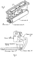
- a printhead 10 with the cover removed, to show the drop generator, 16, catcher 18 and eyelid assembly 12 are all mounted to a common printhead frame 14.
- the catcher is secured to the printhead frame 14.
- the drop generator 16 is then precisely aligned with the catcher 18 as required to properly select print and non-print drops. It is secured to the printhead frame 14 to maintain the precise alignment.
- the eyelid assembly can then be mounted to the printhead frame.
- the eyelid assembly means 12 includes actuator means that can move the eyelid to a sealed position for startup and shutdown, and to an open position for printing to allow ink drops to pass between the catcher and the eyelid and be printed on a print media.
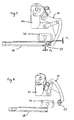
- the electromechanical device of the present invention provides a platform to move an eyelid seal 20 to different operating positions, including a closed position, as illustrated in Fig. 2; a print or open, as illustrated in Fig. 3; and a service position, as illustrated in Fig. 4.
- switch means were used to determine the location of the three operating positions. Replacing the switches with mechanical stops, as in the present invention, reduces complexity and eliminates reliability issues due to switch misplacement or performance variances.
- the eyelid assembly 12 is comprised of the eyelid 18 having an eyelid seal 20, an eyelid base 22, and a multi-link mechanism 24, all illustrated in Fig. 2.
- the multi-link mechanism 24 is employed to define the eyelid seal 20 translation path.
- the various pivot points in the eyelid assembly of the present invention are shown in Fig. 6, where pivots P d and P I are fixed to the eyelid base 22, although base 22 is not shown in Fig. 6.
- Pivots P F1 and P F2 are floating pivots.
- Pivot P d is the drive pivot with the torque supplied by a motor (not shown) directly coupled to pivot arm A. Supplying voltage in the normal direction to the motor produces a counterclockwise force to the pivot arm A. Floating pivot P f1 therefore moves counterclockwise and up.
- a print position stop 32 is placed as shown in Fig. 3.
- the outward pivoting of the eyelid stops when the pivot arm A rotates down and contacts the print position stop 32.
- the print position adjustment screw 36 associated with the pivot arm A can be used to adjust the stop position for the open eyelid.
- the eyelid pivots out to provide a gap, preferably approximately a 0.035 inch gap X 2 , between the eyelid and catcher while printing.
- a service position is provided by rotating the print position stop 32 out of the print mode position, and into a service mode position shown in Fig. 4. In this position, the print position stop 32 no longer serves to stop the rotation of pivot arm A. This allows significantly more rotation of the pivot arm A and, therefore, of the eyelid. In the service position, the pivot stop occurs when the pivot arm A hits the eyelid base 22. As the precise positioning of the service position is not critical, an adjustment means to control this stop position is not required.
- Fig. 5 illustrates the placement of the print position stop 32 relative to other components associated with the eyelid actuating mechanism.
- the print position stop 32 is mounted on the stop rotation shaft 34.
- a tool can be used to engage the end of the stop rotation shaft to allow an operator to effectively rotate the print position stop from its print position to its service position.
- This shaft is biased to the print mode position by stop return springs 28 and 30. Therefore, once the tool for rotating the shaft 34 is removed, the stop will return to its normal position when the eyelid leaves the service position. After the eyelid is again closed, the eyelid will only open up to the print position unless the print position stop is again rotated to allow extension to the service position.
- safety interlocks can be employed to disable high voltages in the printhead when the print position stop is being rotated out of its print position.
- Fig. 5 also shows the placement of the dc motor means 26 which drives pivot arm A by way of torque coupler 48.
- no position sensors are employed to determine the open and closed eyelid positions. Rather, these positions are defined by driving the eyelid assembly to a dead stop.
- the closed position is defined by the eyelid seal making contact with the catcher assembly.
- the print open position is defined by contact between the print position adjustment screw 36 in the pivot arm A making contact with the print position stop 32.
- the service open position is defined by contact between the pivot arm A and the eyelid base 22.
- the torque of the motor is chosen to be high enough to effect a good seal between the eyelid and catcher, but low enough to avoid damage to the various components.
- a model 1516TOO9SR-16/7-592:1-X0520R dc motor with 592:1 reducing gear box from MicroMo Electronics, Inc. is employed. It has been found that this motor can open or close the eyelid rapidly without producing excessive mechanical requirements in the printhead when the eyelid reaches its end of travel conditions. Voltage is supplied to this motor to actuate the eyelid assembly.
- motor current changes significantly when the eyelid stops moving in either the closed or open positions.
- Detection of the motor current therefore provides a means to confirm that the eyelid has stopped moving.
- printer control means can effect a reduction in the motor voltage to the holding voltage from the actuating voltage only after such current detection means have confirmed that the eyelid has stopped.
- a current limited power supply may be used to reduce the holding voltage to the stalled motor.
- the holding voltage is kept the same as the actuating voltage, that is, the voltage is not reduced after the eyelid has reached the end of travel.
- the printer control means monitors the time required for the current detection means to detect that the eyelid has stopped after the onset of applying to the motor an actuation voltage to open or close the eyelid. If the eyelid were to be stuck in one of the positions, the current detection means would detect a stalled eyelid actuator immediately, rather than after the normal eyelid actuation time. The printer control means can therefore identify such an eyelid actuation failure. Conversely, if the current detection means fails to detect the stoppage of the eyelid actuator within an appropriate amount of time, it may imply a failure in the eyelid actuator mechanism, such as a defective motor. Again, the printer control means can identify such a failure.
- the present invention therefore, can actuate eyelid means to closed, print open, and service open positions without the need for position detecting switches, as well as providing means to detect eyelid actuation errors without the need for position detecting switches.
- the present invention further provides means to restrict exposure of untrained operators to the high voltages present within the printhead.
Landscapes
- Ink Jet (AREA)
Abstract
Description
- The present invention relates to the field of continuous ink jet printing and, more particularly, to an eyelid mechanism for sealing the printhead when not printing.
- In continuous ink jet printing systems, the eyelid is a moveable seal which diverts ink on startup into the catcher, thereby recycling the ink while containing it within the printhead. The seal is formed against the lip of the metal catch plate, which is typically about 0.025 inches thick. The eyelid opens about 0.04 inches while the printer is printing, allowing the ink drops to pass onto the print media. The area behind the eyelid, containing the droplet generator and charging leads, is frequently accessed for cleaning over the life of a printhead.
- The printhead is typically located over the top of a roller carrying the print media, with the ink drops moving downward in a roughly vertical direction. To assure good print quality, the printhead is 0.075 to 0.100 inches above the substrate. The eyelid must seal perpendicular to the drop path while not contacting the moving substrate on the roller. The motion paths of prior art have been limited to a linear sliding, or a single pivot. The linear paths of some prior art are guided by slots which are prone to collecting ink residue, leading to sticking or jamming of the eyelid.
- Prior eyelids have used simple spring loaded solenoid actuators. The spring maintains the seal force until the solenoid opens it to a print position. However, the solenoid may create an excessive shock when the eyelid opens and impacts its print position stop. This shock jars the ink jet printhead, causing the printhead to malfunction. To prevent this, cushioning springs or rubber dampers are used to buffer the impact of the eyelid and solenoid plunger at the end of its travel.
- Both the linear slide and the simple pivot eyelids are suitable for a seal moving a small distance from the sealed position to the print position. These configurations, however, do not move far enough to allow the operator to look at the jets and charging electrodes in a horizontal direction while they are cleaning the printhead. It is therefore necessary for the eyelid to be removed by a trained operator for printhead cleaning. This may entail removing screws and covers, necessitating the use of a tool for fasteners and the possibility that the parts may be lost or damaged on reassembly. Proper alignment of the sealing edge with the catchplate may be difficult to obtain after repeated disassembly, leading to leaks or poor startups.
- An additional safety issue exists, since the printhead contains high voltage (∼150 Volts). While operating, it is necessary to maintain proper ingress protection to avoid accidental contact with the charging electrodes. In the existing art the removal of covers by trained service personnel is the only means provided to prevent accidental access to the electrodes while the high voltage is on.
- As mentioned earlier, it is possible for the eyelid to become stuck or jammed. The prior art, with a simple solenoid actuator, has no feedback of eyelid position or presence. If the eyelid jams while closing, no indication is made to the system of the malfunction. This could result in ink spraying out of the printhead during start up or shut down.
- One existing patent, U.S. Patent No. 6,247,781, described an improved eyelid mechanism to overcome some of the problems of other prior art systems. The '781 patent showed an eyelid that could be positioned, using a stepper motor, into the three positions of closed, print and service. The eyelid closed position seals the eyelid against the catcher to prevent ink from leaking from the printhead during start up and shutdown operations. The print position moves the eyelid seal away from the catcher to allow print drops to pass between the eyelid and the catcher on their way to the print media. A service position moves the eyelid much farther away from the catcher, providing a printhead operator better access for cleaning the printhead orifice plate and charge plate. It employs electro mechanical switches and a stepper motor drive to facilitate movement of the eyelid to those three positions. During motion of the eyelid, the eyelid is prevented from making contact with the paper. The stepper motor drives the eyelid into the three positions. Switch means detect that the eyelid is properly actuated to the desired locations.
- While the eyelid mechanism of the '781 was effective in providing the three operating positions, it has been found that the switch means for detecting the eyelid position had certain drawbacks. First, the switch means has proven to be cumbersome to locate properly on the eyelid. Misplacement of the switches could result in either insufficient or excessive sealing forces being supplied to seal against the catcher. Second, the reliability of the switches exposed to the operating environment of the inkjet printhead can be inadequate. Third, the placement of the switches may interfere with the desired flow of air through the printhead. Fourth, a primary function of the switches was to detect possible eyelid actuation errors. The most common error has been a failure of the eyelid to open, due to the eyelid sticking to the catcher pan in the closed position.
- It would be desirable to provide an improved eyelid actuation means to provide for the required three operating positions, that overcomes the problems associated with the prior art.
- This need is met by the eyelid system of the present invention, wherein a multi-link mechanism is employed to define the eyelid seal translation path.
- In accordance with one aspect of the present invention, a four-bar linkage is employed to define the eyelid translation path, using a gear box reduced dc motor rather than a stepper motor. The eyelid is moved to the closed position by supplying the motor with voltage in the normal direction. Reversing the voltage to the dc motor drives the eyelid to the open position. In both the open and closed position, the motor is driven to a dead stop. In the closed position, the dead stop is defined by contact between the eyelid seal and the catcher assembly. In the open position, the dead stop is defined by contact the linkage arm mechanism with a print position stop. Shifting the position of the print position stop allows the eyelid to open to a service position.
- Other objects and advantages of the invention will be apparent from the following description, the accompanying drawing and the appended claims.
-
- Fig. 1 is a perspective view of a printhead with the cover removed to illustrate the eyelid mechanism mounted to the printhead frame;
- Fig. 2 illustrates the eyelid in a closed position;
- Fig. 3 illustrates the eyelid in a print position;
- Fig. 4 illustrates the eyelid in a service position;
- Fig. 5 is a perspective view showing placement of the print position stop on the eyelid actuating mechanism; and
- Fig. 6 illustrates the eyelid pivot points.
- Referring to the drawings, and particularly to Fig. 1, there is illustrated a
printhead 10, with the cover removed, to show the drop generator, 16,catcher 18 andeyelid assembly 12 are all mounted to a common printhead frame 14. During assembly, the catcher is secured to the printhead frame 14. Thedrop generator 16 is then precisely aligned with thecatcher 18 as required to properly select print and non-print drops. It is secured to the printhead frame 14 to maintain the precise alignment. The eyelid assembly can then be mounted to the printhead frame. The eyelid assembly means 12 includes actuator means that can move the eyelid to a sealed position for startup and shutdown, and to an open position for printing to allow ink drops to pass between the catcher and the eyelid and be printed on a print media. - Referring now to Figs. 2-4, the electromechanical device of the present invention provides a platform to move an
eyelid seal 20 to different operating positions, including a closed position, as illustrated in Fig. 2; a print or open, as illustrated in Fig. 3; and a service position, as illustrated in Fig. 4. In the prior art, switch means were used to determine the location of the three operating positions. Replacing the switches with mechanical stops, as in the present invention, reduces complexity and eliminates reliability issues due to switch misplacement or performance variances. - The
eyelid assembly 12 is comprised of theeyelid 18 having aneyelid seal 20, aneyelid base 22, and a multi-link mechanism 24, all illustrated in Fig. 2. The multi-link mechanism 24 is employed to define theeyelid seal 20 translation path. The various pivot points in the eyelid assembly of the present invention are shown in Fig. 6, where pivots Pd and PI are fixed to theeyelid base 22, althoughbase 22 is not shown in Fig. 6. Pivots PF1 and PF2 are floating pivots. Pivot Pd is the drive pivot with the torque supplied by a motor (not shown) directly coupled to pivot arm A. Supplying voltage in the normal direction to the motor produces a counterclockwise force to the pivot arm A. Floating pivot Pf1 therefore moves counterclockwise and up. This, in turn, causes theeyelid 18 to pivot around Pf2 such that theeyelid seal 20 rotates down. This allows the eyelid to seal against the bottom of the catcher, as illustrated in Fig. 2. The motion stops when the eyelid seal contacts the catcher face at catcher assembly 19. - Reversing the polarity of the voltage to the dc motor reverses the motor torque and the motion of each of the pivot arms, causing the eyelid seal to pivot away from the catcher. In normal operation of the printhead, a print position stop 32 is placed as shown in Fig. 3. The outward pivoting of the eyelid stops when the pivot arm A rotates down and contacts the
print position stop 32. The printposition adjustment screw 36 associated with the pivot arm A can be used to adjust the stop position for the open eyelid. In a preferred embodiment of the present invention, the eyelid pivots out to provide a gap, preferably approximately a 0.035 inch gap X2, between the eyelid and catcher while printing. - In accordance with the present invention, a service position is provided by rotating the print position stop 32 out of the print mode position, and into a service mode position shown in Fig. 4. In this position, the print position stop 32 no longer serves to stop the rotation of pivot arm A. This allows significantly more rotation of the pivot arm A and, therefore, of the eyelid. In the service position, the pivot stop occurs when the pivot arm A hits the
eyelid base 22. As the precise positioning of the service position is not critical, an adjustment means to control this stop position is not required. - Fig. 5 illustrates the placement of the print position stop 32 relative to other components associated with the eyelid actuating mechanism. As shown in Fig. 5, the print position stop 32 is mounted on the
stop rotation shaft 34. A tool can be used to engage the end of the stop rotation shaft to allow an operator to effectively rotate the print position stop from its print position to its service position. This shaft is biased to the print mode position by stop return springs 28 and 30. Therefore, once the tool for rotating theshaft 34 is removed, the stop will return to its normal position when the eyelid leaves the service position. After the eyelid is again closed, the eyelid will only open up to the print position unless the print position stop is again rotated to allow extension to the service position. - Since the interior of the printhead can contain high voltage electrodes which might be exposed to contact by the operator, safety interlocks, not shown, can be employed to disable high voltages in the printhead when the print position stop is being rotated out of its print position. Alternatively, one might require a special tool, available to trained operators, to engage and rotate the stop rotation shaft.
- Fig. 5 also shows the placement of the dc motor means 26 which drives pivot arm A by way of torque coupler 48. In the present invention, no position sensors are employed to determine the open and closed eyelid positions. Rather, these positions are defined by driving the eyelid assembly to a dead stop. The closed position is defined by the eyelid seal making contact with the catcher assembly. The print open position is defined by contact between the print
position adjustment screw 36 in the pivot arm A making contact with theprint position stop 32. The service open position is defined by contact between the pivot arm A and theeyelid base 22. - In accordance with the present invention, the torque of the motor is chosen to be high enough to effect a good seal between the eyelid and catcher, but low enough to avoid damage to the various components. For example, in a preferred embodiment of the present invention, a model 1516TOO9SR-16/7-592:1-X0520R dc motor with 592:1 reducing gear box from MicroMo Electronics, Inc., is employed. It has been found that this motor can open or close the eyelid rapidly without producing excessive mechanical requirements in the printhead when the eyelid reaches its end of travel conditions. Voltage is supplied to this motor to actuate the eyelid assembly.
- In accordance with the present invention, motor current changes significantly when the eyelid stops moving in either the closed or open positions.
- Detection of the motor current therefore provides a means to confirm that the eyelid has stopped moving.
- In one preferred embodiment, printer control means, not shown, can effect a reduction in the motor voltage to the holding voltage from the actuating voltage only after such current detection means have confirmed that the eyelid has stopped. In another embodiment, a current limited power supply may be used to reduce the holding voltage to the stalled motor. In another embodiment, the holding voltage is kept the same as the actuating voltage, that is, the voltage is not reduced after the eyelid has reached the end of travel.
- In another embodiment, the printer control means monitors the time required for the current detection means to detect that the eyelid has stopped after the onset of applying to the motor an actuation voltage to open or close the eyelid. If the eyelid were to be stuck in one of the positions, the current detection means would detect a stalled eyelid actuator immediately, rather than after the normal eyelid actuation time. The printer control means can therefore identify such an eyelid actuation failure. Conversely, if the current detection means fails to detect the stoppage of the eyelid actuator within an appropriate amount of time, it may imply a failure in the eyelid actuator mechanism, such as a defective motor. Again, the printer control means can identify such a failure.
- The present invention, therefore, can actuate eyelid means to closed, print open, and service open positions without the need for position detecting switches, as well as providing means to detect eyelid actuation errors without the need for position detecting switches. The present invention further provides means to restrict exposure of untrained operators to the high voltages present within the printhead.
- The invention has been described in detail with particular reference to certain preferred embodiments thereof, but it will be understood that modifications and variations can be effected within the spirit and scope of the invention.
Claims (10)
- An ink jet printer system, comprising:an ink jet printhead having an ink drop generator, a catcher located adjacent to the ink drop generator, and a catcher plate located below the catcher;an eyelid for sealing ink within the printhead on startup of the printer system;an actuating means for opening and closing the eyelid;a movable eyelid stop means which define a first eyelid open position to facilitate printing when said movable eyelid stop means is in a first position, and a second and wider eyelid open position to facilitate printhead servicing when said movable eyelid stop means is shifted to a second position; andshifting means for shifting the movable eyelid stop means between the first and second positions.
- An ink jet printer system as claimed in claim 1 wherein the shifting means comprises means to rotate the movable eyelid stop means.
- An ink jet printer system as claimed in claim 1 wherein the actuating means comprises a motor.
- An ink jet printer system as claimed in claim 1 wherein the actuating means comprises a multi-pivot actuating means.
- An ink jet printer system as claimed in claim 1 further comprising safety interlock means for disabling high voltage electrodes when the movable eyelid stop means are not in the first open position.
- An eyelid assembly for a continuous ink jet printing system, the eyelid assembly comprising:a dc motor for moving the eyelid to a plurality of positions; andeyelid stop means for stopping the eyelid at any of the plurality of positions.
- An eyelid assembly as claimed in claim 6 wherein the plurality of eyelid positions comprises at least a closed position, a print open position and a service open position for the eyelid.
- An eyelid assembly as claimed in claim 6 wherein changes in current of the dc motor indicate movement of the eyelid to one or more of the plurality of positions.
- An eyelid assembly as claimed in claim 6 further comprising a multi arm linkage along a predetermined eyelid translation path
- An eyelid assembly as claimed in claim 6 wherein the dc motor comprises a gear reduced dc motor.
Applications Claiming Priority (2)
| Application Number | Priority Date | Filing Date | Title |
|---|---|---|---|
| US10/254,726 US6910756B2 (en) | 2002-09-25 | 2002-09-25 | Eyelid with mechanically driven service position override |
| US254726 | 2002-09-25 |
Publications (2)
| Publication Number | Publication Date |
|---|---|
| EP1403057A1 true EP1403057A1 (en) | 2004-03-31 |
| EP1403057B1 EP1403057B1 (en) | 2005-12-14 |
Family
ID=31977833
Family Applications (1)
| Application Number | Title | Priority Date | Filing Date |
|---|---|---|---|
| EP03255927A Expired - Lifetime EP1403057B1 (en) | 2002-09-25 | 2003-09-23 | Eyelid with mechanically driven service position override |
Country Status (3)
| Country | Link |
|---|---|
| US (1) | US6910756B2 (en) |
| EP (1) | EP1403057B1 (en) |
| DE (1) | DE60302735T2 (en) |
Families Citing this family (7)
| Publication number | Priority date | Publication date | Assignee | Title |
|---|---|---|---|---|
| US9566798B1 (en) | 2016-05-24 | 2017-02-14 | Eastman Kodak Company | Inkjet printhead assembly with repositionable shutter |
| US9623689B1 (en) | 2016-05-24 | 2017-04-18 | Eastman Kodak Company | Modular printhead assembly with common center rail |
| US9527319B1 (en) | 2016-05-24 | 2016-12-27 | Eastman Kodak Company | Printhead assembly with removable jetting module |
| US9789714B1 (en) | 2016-10-21 | 2017-10-17 | Eastman Kodak Company | Modular printhead assembly with tilted printheads |
| US9962943B1 (en) | 2016-11-07 | 2018-05-08 | Eastman Kodak Company | Inkjet printhead assembly with compact repositionable shutter |
| US9969178B1 (en) | 2016-11-07 | 2018-05-15 | Eastman Kodak Company | Inkjet printhead assembly with repositionable shutter mechanism |
| US10052868B1 (en) | 2017-05-09 | 2018-08-21 | Eastman Kodak Company | Modular printhead assembly with rail assembly having upstream and downstream rod segments |
Citations (1)
| Publication number | Priority date | Publication date | Assignee | Title |
|---|---|---|---|---|
| EP1013439A2 (en) * | 1998-12-14 | 2000-06-28 | SCITEX DIGITAL PRINTING, Inc. | Ink diverter for ink-jet printhead |
-
2002
- 2002-09-25 US US10/254,726 patent/US6910756B2/en not_active Expired - Lifetime
-
2003
- 2003-09-23 EP EP03255927A patent/EP1403057B1/en not_active Expired - Lifetime
- 2003-09-23 DE DE60302735T patent/DE60302735T2/en not_active Expired - Lifetime
Patent Citations (2)
| Publication number | Priority date | Publication date | Assignee | Title |
|---|---|---|---|---|
| EP1013439A2 (en) * | 1998-12-14 | 2000-06-28 | SCITEX DIGITAL PRINTING, Inc. | Ink diverter for ink-jet printhead |
| US6247781B1 (en) | 1998-12-14 | 2001-06-19 | Scitex Digital Printing, Inc. | Ink jet printhead with an improved eyelid system |
Also Published As
| Publication number | Publication date |
|---|---|
| EP1403057B1 (en) | 2005-12-14 |
| US20040056920A1 (en) | 2004-03-25 |
| DE60302735D1 (en) | 2006-01-19 |
| DE60302735T2 (en) | 2006-09-07 |
| US6910756B2 (en) | 2005-06-28 |
Similar Documents
| Publication | Publication Date | Title |
|---|---|---|
| EP1013439B1 (en) | Ink diverter for ink-jet printhead | |
| EP1403057B1 (en) | Eyelid with mechanically driven service position override | |
| EP0720912B1 (en) | Maintenance device in an ink jet printing apparatus | |
| EP1652675B1 (en) | Methods and apparatus for aerosol extraction in fluid ejection-devices | |
| EP0720913A2 (en) | Maintenance device in an ink jet printing apparatus | |
| KR20040028233A (en) | maintenance apparatus of an ink-jet printer and wiper-positioning mathod therefor | |
| US8408671B2 (en) | Ink jet recording apparatus equipped with ultraviolet light irradiation device | |
| US20040012651A1 (en) | Independent wiping of printhead | |
| US9211716B2 (en) | Capping device | |
| US12545036B2 (en) | Medium transport device and recording apparatus | |
| US4285604A (en) | Ribbon shield for printer | |
| MX9801299A (en) | Ink jet printer including a disengageable medium transport for jam clearance. | |
| CN1136099C (en) | Ink jet head maintenance mechanism | |
| JP2015051574A (en) | Image forming apparatus and control method therefor | |
| WO2009154680A1 (en) | Continuous inkjet printhead nozzle cap | |
| JPH06171079A (en) | Ink jet printer | |
| EP2755825B1 (en) | Capping device | |
| JP2694842B2 (en) | Ink jet recording device | |
| CA2292031A1 (en) | Printhead installation and retaining mechanism | |
| CN111137030A (en) | Printing head gap adjusting device with side nut motor | |
| US20250196501A1 (en) | Head unit and ink jet recording device | |
| US20250262880A1 (en) | Liquid discharge device | |
| US20250066147A1 (en) | Sheet stacking apparatus and image forming apparatus | |
| US20210291529A1 (en) | Printing apparatus | |
| JP2635307B2 (en) | Image forming device |
Legal Events
| Date | Code | Title | Description |
|---|---|---|---|
| PUAI | Public reference made under article 153(3) epc to a published international application that has entered the european phase |
Free format text: ORIGINAL CODE: 0009012 |
|
| AK | Designated contracting states |
Kind code of ref document: A1 Designated state(s): AT BE BG CH CY CZ DE DK EE ES FI FR GB GR HU IE IT LI LU MC NL PT RO SE SI SK TR |
|
| AX | Request for extension of the european patent |
Extension state: AL LT LV MK |
|
| RAP1 | Party data changed (applicant data changed or rights of an application transferred) |
Owner name: EASTMAN KODAK COMPANY |
|
| 17P | Request for examination filed |
Effective date: 20040911 |
|
| AKX | Designation fees paid |
Designated state(s): DE FR GB |
|
| 17Q | First examination report despatched |
Effective date: 20050221 |
|
| GRAP | Despatch of communication of intention to grant a patent |
Free format text: ORIGINAL CODE: EPIDOSNIGR1 |
|
| GRAS | Grant fee paid |
Free format text: ORIGINAL CODE: EPIDOSNIGR3 |
|
| GRAA | (expected) grant |
Free format text: ORIGINAL CODE: 0009210 |
|
| AK | Designated contracting states |
Kind code of ref document: B1 Designated state(s): DE FR GB |
|
| REG | Reference to a national code |
Ref country code: GB Ref legal event code: FG4D |
|
| REF | Corresponds to: |
Ref document number: 60302735 Country of ref document: DE Date of ref document: 20060119 Kind code of ref document: P |
|
| ET | Fr: translation filed | ||
| PLBE | No opposition filed within time limit |
Free format text: ORIGINAL CODE: 0009261 |
|
| STAA | Information on the status of an ep patent application or granted ep patent |
Free format text: STATUS: NO OPPOSITION FILED WITHIN TIME LIMIT |
|
| 26N | No opposition filed |
Effective date: 20060915 |
|
| PGFP | Annual fee paid to national office [announced via postgrant information from national office to epo] |
Ref country code: FR Payment date: 20120910 Year of fee payment: 10 |
|
| PGFP | Annual fee paid to national office [announced via postgrant information from national office to epo] |
Ref country code: GB Payment date: 20130827 Year of fee payment: 11 |
|
| PGFP | Annual fee paid to national office [announced via postgrant information from national office to epo] |
Ref country code: DE Payment date: 20130930 Year of fee payment: 11 |
|
| REG | Reference to a national code |
Ref country code: FR Ref legal event code: ST Effective date: 20140530 |
|
| PG25 | Lapsed in a contracting state [announced via postgrant information from national office to epo] |
Ref country code: FR Free format text: LAPSE BECAUSE OF NON-PAYMENT OF DUE FEES Effective date: 20130930 |
|
| REG | Reference to a national code |
Ref country code: DE Ref legal event code: R119 Ref document number: 60302735 Country of ref document: DE |
|
| GBPC | Gb: european patent ceased through non-payment of renewal fee |
Effective date: 20140923 |
|
| PG25 | Lapsed in a contracting state [announced via postgrant information from national office to epo] |
Ref country code: DE Free format text: LAPSE BECAUSE OF NON-PAYMENT OF DUE FEES Effective date: 20150401 Ref country code: GB Free format text: LAPSE BECAUSE OF NON-PAYMENT OF DUE FEES Effective date: 20140923 |