EP1403005A1 - Adjustable depth control for fastener driving tool - Google Patents
Adjustable depth control for fastener driving tool Download PDFInfo
- Publication number
- EP1403005A1 EP1403005A1 EP03019710A EP03019710A EP1403005A1 EP 1403005 A1 EP1403005 A1 EP 1403005A1 EP 03019710 A EP03019710 A EP 03019710A EP 03019710 A EP03019710 A EP 03019710A EP 1403005 A1 EP1403005 A1 EP 1403005A1
- Authority
- EP
- European Patent Office
- Prior art keywords
- depth control
- control probe
- piston
- fastener
- driving
- Prior art date
- Legal status (The legal status is an assumption and is not a legal conclusion. Google has not performed a legal analysis and makes no representation as to the accuracy of the status listed.)
- Granted
Links
Images


Classifications
-
- B—PERFORMING OPERATIONS; TRANSPORTING
- B25—HAND TOOLS; PORTABLE POWER-DRIVEN TOOLS; MANIPULATORS
- B25C—HAND-HELD NAILING OR STAPLING TOOLS; MANUALLY OPERATED PORTABLE STAPLING TOOLS
- B25C1/00—Hand-held nailing tools; Nail feeding devices
- B25C1/08—Hand-held nailing tools; Nail feeding devices operated by combustion pressure
-
- B—PERFORMING OPERATIONS; TRANSPORTING
- B25—HAND TOOLS; PORTABLE POWER-DRIVEN TOOLS; MANIPULATORS
- B25C—HAND-HELD NAILING OR STAPLING TOOLS; MANUALLY OPERATED PORTABLE STAPLING TOOLS
- B25C1/00—Hand-held nailing tools; Nail feeding devices
- B25C1/008—Safety devices
Definitions
- the present invention is directed to a depth of drive control for use with a fastener driving tool, in particular to an adjustable depth of drive control for a fastener driving tool.
- Portable fastener driving tools for driving staples, nails and other fasteners are widely used for the attachment of substrates.
- Many fastener driving tools have attempted to control fastener driving depth. Effectively controlling driving depth has been difficult in the past because each fastener is usually driven with the same amount of energy each time that the tool is fired. This has been known to cause fasteners to be driven to an inconsistent depth when there was variation in the density of substrates into which the fasteners are to be driven, for example soft and hard woods.
- a problem that has been known to occur with many of the tools and depth controls described above is inconsistency in driving depth depending on how much driving and recoiling force is created.
- many tools are able to alter the amount of driving energy provided, such as by increasing or decreasing the air pressure fed to the tool, which alters the driving depth of the fastener.
- fastener driving tools including the drive probe, are known to recoil away from the substrate after firing. Because the drive probe is an integral part of the tool body, the drive probe recoils with the tool body so that the drive probe is moving away from the substrate as the piston is driving the fastener. Tools have also been known to recoil at different speeds so that depth control of the fastener becomes less predictable because the piston is driven to different depths relative to the substrate surface.
- What is needed is a depth of drive control for a fastener driving tool that will effectively, accurately, and consistently control the driving depth of a fastener under various operating conditions while being able to control the second.
- a fastener driving tool having a novel depth of drive control.
- the fastener driving tool includes a tool body having a cylinder with an axis, wherein the cylinder encloses a piston, and wherein the piston is driven in a driving direction, a depth control probe, and a bumper associated with the depth control probe, the bumper having a trailing surface, wherein the depth control probe is movable with respect to the tool body between an extended position and a retracted position, wherein the depth control probe creates a space having a predetermined length between a surface of a substrate and the trailing surface of the bumper, and wherein a surface of the piston hits the trailing surface of the bumper after the fastener is driven.
- a novel fastener driving tool for axially driving a fastener.
- the fastener driving tool includes a tool body having a cylinder with an axis, the cylinder enclosing a bumper and a piston, wherein the piston is driven in a driving direction, wherein the tool body includes a lifting surface, a depth control probe having a substrate contacting surface and a recoil surface, wherein the depth control probe is movable with respect to the tool body between a retracted position and an extended position, wherein the recoil surface is spaced away from the lifting surface and the substrate contacting surface is in contact with a substrate when the depth control probe is in the retracted position, and wherein the lifting surface is in contact with the recoil surface, the substrate contacting surface is not in contact with the substrate, and the bumper is in contact with the piston when the depth control probe is in the extended position.
- a method of controlling the driving depth of a fastener driving tool includes the steps of providing a fastener driving tool having a tool body with an axis, the tool body enclosing a piston, a depth control probe, a bumper associated with the depth control probe, the bumper having a trailing surface, wherein the depth control probe is movable relative to the tool body, and wherein the depth control probe creates a space of a predetermined length between a surface of a substrate and the trailing surface of the bumper, pushing the depth control probe against the surface of the substrate, firing the tool so that the piston is driven in a driving direction, driving a fastener in the driving direction with the piston, hitting the trailing surface of the bumper with the piston so that the piston is no longer moving in the driving direction.
- Adjustable depth control 10 uses a bumper 46 to stop the forward motion of a driving piston. 12 and exploits the recoil of tool 2 to lift a depth control probe 14 off a substrate 4 into which a fastener 8 is being driven.
- Fastener driving tool 2 can be one of several types of tools for driving a fastener 8 into substrate 4, such as a gas combustion powered or powder actuated tool, but a preferred tool 2 is a pneumatically powered tool.
- FIG. 1 The right side of FIG. 1 is generally referred to as the driving side, because this is the side of tool 2 that piston 12 is driven towards, and the left side is generally referred to as the trailing side.
- the direction in which piston 12 is driven is generally referred to as the driving direction, while the opposite direction is generally referred to as the trailing direction.
- tool 2 could be operated in several orientations, such as horizontal or vertical, without varying from the scope of the present invention.
- tool 2 includes a housing 18 and a tool body 20a for enclosing a piston 12.
- Tool body 20a is generally cylindrical in shape and has a central axis 24 running through the length of tool 2.
- Housing 18 includes a handle 26 radially extending away from tool body 20a and a trigger 28 for actuating tool 2.
- a magazine (not shown) for feeding fasteners 8 to tool 2.
- Tool 2 may also include a trigger probe 34, which prevents tool 2 from being fired unless tool 2 is pushed against substrate 4.
- Piston 12 includes a head 36 and a driving rod 38 for driving a fastener 8 into a substrate 4.
- Piston 12 is also generally cylindrical in shape and is aligned coaxially with axis 24 of tool body 20a.
- Piston head 36 includes a driving surface 37, which hits surface 68 of bumper 46, as described below.
- a representative fastener 8, shown in FIG. 2 has a head 40 at the trailing end of fastener 8, a point 42 at the driving end and a shank 44 axially extending between point 42 and head 40.
- a driving end 39 of piston rod 38 hits a trailing surface 86 of fastener head 40 in order to drive fastener 8 into a substrate 4.
- piston 12 includes an extended length P between driving surface 37 of piston head 36 and driving end 39 of driving rod 38.
- tool 2 includes a bumper 46 enclosed within tool body 20a.
- Bumper 46 protects piston 12 and tool body 20a from damage due to the high forces associated with tool 2.
- Bumper 46 is associated with the trailing end 56 of depth control probe 14 so that bumper 46 and depth control probe 14 move together.
- Bumper 46 can be connected to depth control probe 14 (not shown), or bumper 46 can be retained within a portion of depth control probe 14, such as a bumper holder 48 integral with depth control probe 14, or bumper 46 can be adjacent to depth control probe 14.
- Bumper 46 is also used by depth control 10 to stop the motion of piston 12 in the driving direction when driving surface 37 of piston head 36 hits bumper 46 which stops the driving of fastener 8 into substrate, as described below.
- Tool 2 is designed to stop the driving motion of piston 12 with bumper 46 immediately after piston 12 has driven fastener 8 to . the desired depth.
- Bumper 46 may be of any geometrical shape, but should have generally the same cross-sectional shape as piston 12 and tool body 20a.
- bumper 46 has a generally cylindrical shape, with a generally annular cross section so that driving rod 38 can pass through bumper 46.
- Bumper 46 may be made of any material that provides some elasticity to absorb shock from piston 12, is substantially heat resistant to the highest operating temperature created by friction within tool 2 and sufficiently wear resistant so that each bumper 46 may last for a substantial number of firings of tool 2 between change-outs. Although the material of bumper 46 should be chosen for its ability to consistently withstand the forces within tool 2, it eventually will wear down. Therefore, it is preferred that the material of bumper 46 be relatively inexpensive, allowing multiple change-outs to be cost-effective. A preferred material would be a resilient, polymeric plastic or rubber, an example being urethane.
- tool 2 is designed so that depth control probe 14 will not recoil with tool body 20a, but rather will remain adjacent to substrate 4.
- Bumper 46 is retained by a bumper holder 48, which is operationally associated with depth control 10 so that bumper 46, bumper holder 48, and depth control probe 14 move together.
- depth control probe 14 is generally cylindrical in shape and is aligned coaxially with tool body axis 24 and includes a trailing portion 50a, and an adjustable portion 52a. Adjustable portion 52a can be axially adjusted in the driving direction or the trailing direction relative to trailing portion 50a so that an effective length L, shown in FIG. 2, of depth control probe 14 and bumper 46 can be chosen in order to control the driving depth of fastener 8, as described below.
- Depth control probe 14 extends axially away from tool body 20a in the driving direction, as shown in FIG. 1, but depth control probe 14 is not fixedly connected to tool body 20a, as traditional nosepieces and drive probes usually are.
- depth control probe 14 can move in the axial direction independently of tool body 20a between an extended position, as shown in FIGS. 1 and 3, to a retracted position, shown in FIG. 2. Because depth control probe 14 moves independently from tool body 20a, depth control probe 14 does not recoil with tool body 20a so that depth control probe 14 can consistently and accurately control the driving depth and driving location of fastener 8, as described below.
- a spring 54a is included in order to bias depth control probe 14 toward the extended position. Spring 54a also biases depth control probe 14 to remain pushed against substrate 4 while tool body 20a recoils in the trailing direction.
- Bumper holder 48 is connected to a trailing end 56 of depth control probe 14 so that bumper holder 48 is operationally associated with depth control probe 14 so that bumper holder 48 moves with depth control probe 14.
- bumper holder 48 is integrally formed with trailing end 56 of trailing portion 50a of depth control probe 14.
- Bumper holder 48 is generally cylindrical in shape and has a cylindrical portion 58 with a flange 60 connected to the driving end of cylindrical portion 58, where flange 60 radially extends outwardly from trailing end 56 of depth control probe 14 to cylindrical portion 58 of bumper holder 48 so that flange 60 is an annulus formed between depth control probe 14 and cylindrical portion 58.
- Flange 60 of bumper holder 48 includes a leading surface 62 on the driving side of flange 60, and a trailing surface 64 for supporting bumper 46.
- piston 12 As piston 12 is driven in the driving direction, tool body 20a moves in the trailing direction due to recoil and depth control probe 14, bumper holder 48 and bumper 46 remain essentially stationary, with a substrate contacting surface 66 of depth control probe 14 pushed against substrate 4 by spring 54a. Piston 12 moves in the driving direction until driving surface 37 of piston head 36 eventually hits a trailing surface 68 of bumper 46. At this point, driving end 39 of piston 12 has reached a farthest point F relative to depth control probe 14 and piston 12 cannot move any further in the driving direction because the driving energy in piston 12 has been dissipated by bumper 46.
- Tool body 20a continues to recoil away from the substrate 4, carrying with it piston 12, bumper 46, and depth control probe 14, as shown in FIG. 4 and described below.
- piston 12 is no longer providing driving energy to drive fastener 8 into substrate 4
- friction between substrate 4 and shank 44 of fastener 8 effectively stops fastener 8 immediately after piston 12 has stopped providing driving energy so that fastener 8 will not be driven forward any further than it already has been by piston 12.
- a trailing surface 68 of bumper 46 remains generally stationary at a predetermined length from surface 6 of substrate 4 equal to the effective length L of depth control probe 14 so that driving surface 37 of piston head 36 hits bumper 46 at the exact moment that driving end 39 of piston 12 has reached its farthest point F, causing fastener head 40 to be driven to the desired depth.
- depth control probe 14 creates a space of a predetermined length between substrate surface 6 and bumper 46 so that bumper 46 is at a predetermined axial position relative to substrate 4.
- Depth control probe 14 includes a depth control adjustment 70a, 70b in order to axially adjust the effective length L of depth control probe 14 to control the driving depth of fastener 8, as described below.
- Depth control probe 14 includes a trailing portion 50a, 50b and an adjustable portion 52a, 52b that is adjustably connected to trailing portion 50a, 50b so that adjustable portion 52a, 52b axially extends in the driving direction away from trailing portion 50a, 50b.
- depth control adjustment 70a includes an adjustment slot 72 in adjustable portion 52a, a threaded bolt 74 connected to trailing portion 50a, wherein bolt 74 fits into slot 72, and a nut 76 placed on bolt 74.
- Adjustment slot 72 extends in the axial direction so that when nut 76 is loosened, bolt 74 can slide freely along slot 72.
- nut 76 is tightened so that it forces adjustable portion 52a tight against trailing portion 50a, causing both portions to be locked together so that they move together.
- An alternative of this embodiment is an adjustable slot in trailing portion 50a with the bolt being connected to adjustable portion 52a. This alternative performs the same function of axially adjusting the length L of depth control probe 14 and would not vary from the scope of the present invention.
- depth control adjustment 70b includes threading 78 on the driving end of trailing portion 50b and corresponding threading 80 included on the trailing end of adjustable portion 52b, so that one fits radially within the other.
- the axial length L of depth control probe 14 is adjusted by rotating adjustable portion 52b with respect to trailing portion 50b, which causes adjustable portion threading 80 to engage trailing portion threading 78 so that adjustable portion 52b moves either in the driving direction or the trailing direction with respect to trailing portion 50b, depending on which direction adjustable portion 52b is rotated.
- FIGS. 6-8 show trailing portion threading 78 being on interior surface 82 of trailing portion 50b and adjustable portion threading 80 being on an exterior surface 84 of adjustable portion 52b.
- the diameter of trailing portion threading 78 is slightly larger than the diameter of adjustable portion threading 80 so that adjustable portion threading 80 can be threadingly engaged radially within trailing portion threading 78.
- trailing portion threading is on an exterior surface of the trailing portion while the adjustable portion threading is on an interior surface of the adjustable portion.
- the diameter of the adjustable portion threading is slightly smaller than the diameter of the trailing portion threading so that the trailing portion threading can be threadingly engaged radially within the adjustable portion threading.
- Depth control adjustment 70b can adjust the effective length L of depth control probe 14 to at least three predetermined settings.
- depth control probe 14 is set so that substrate contacting surface 66 is in the trailing direction with respect to driving end 39 of piston 12 at its farthest point F.
- the effective length L of depth control probe 14 in the first setting is shorter than the extended length P of piston 12 so that the farthest point F is below, or in the driving direction of substrate surface 6.
- FIG. 7 shows a second setting where substrate contacting surface 66 of depth control probe 14 is set so that it is essentially flush with driving end 39 of driving rod 38.
- the effective length L of depth control probe 14 is essentially equal to the extended length P of piston 12 so that the farthest point F is even with substrate surface 6.
- a trailing surface 86 of fastener head 40 is flush with surface 6 of substrate 4.
- depth control probe 14 extends past driving end 39 of driving rod 38 when piston 12 is in its fully driven position.
- the effective length L of depth control probe 14 is longer than the extended length P of piston 12 so that the farthest point F is in the trailing direction of substrate surface 6.
- trailing surface 86 of head 40 will stand off above the surface 6 of substrate 4 at a distance equal to the difference between extended length P and length L.
- depth control probe 14 creates a space, either in the trailing or the driving direction, between surface 6 of substrate 4 and the farthest point F that piston 12 can reach, allowing the position of point F relative to substrate surface 6 to be changed.
- depth control adjustment 70b is in its third setting so that fastener head 40 will stand off from surface 6 of substrate 4
- depth control probe 14 creates a space between surface 6 and tool 2 so that the farthest point F that piston driving end 39 can reach is above surface 6, as shown in FIG. 8.
- depth control probe 14 For some applications it may be desirable to prevent depth control probe 14 from leaving an impact mark on substrate surface 6. In still other applications it may be desirable to leave a controlled and exact impact mark on the substrate surface, such as to leave a distinct design, or "signature mark.”
- the present invention can accurately control the formation of impact marks on the surface of a substrate. This novel feature advantageously uses the recoil created by the tool 2 to lift depth control probe 14 off substrate 4 at a desired moment.
- a pneumatic tool 2 As shown in FIG. 1, compressed air is fed into cylinder 22.
- the compressed air exerts a force on both piston 12 and tool body 20a, creating a driving force on piston 12 in the driving direction and a reactive force on the tool body 20a in the trailing direction, where the trailing motion of tool body 20a is commonly referred to as recoil.
- piston 12 Because tool body 20a has a substantially higher mass than piston 12, piston 12 will travel in the driving direction much faster than tool body 20a will travel in the trailing direction. In one embodiment, after firing, piston 12 will have traveled about 4 inches in the driving direction while tool body 20a will have traveled less than about 0.5 inches in the trailing direction.
- a lifting surface 90 is included that uses the recoil motion of tool body 20a to lift depth control probe 14 off surface 6 of substrate 4.
- Lifting surface 90 faces generally in the trailing direction and is operationally associated with tool body 20a so that when tool body 20a recoils in the trailing direction, lifting surface 90 also moves in the trailing direction.
- Depth control 10 also includes a recoil surface 92 that faces generally in the driving direction and is operationally associated with depth control probe 14 so that when recoil surface 92 moves so does depth control probe 14.
- lifting surface 90 and recoil surface 92 are axially spaced apart by a distance D.
- recoil causes tool body 20a to move in the trailing direction and lifting surface 90 moves with tool body 20a.
- recoil surface 92 is biased by spring 54a to remain essentially stationary.
- the distance D between lifting surface 90 and recoil surface 92 is closed by the recoil motion of lifting surface 90, as in FIG. 3, and lifting surface 90 engages recoil surface 92, lifting depth control probe 14 off substrate 4, as in FIG. 4.
- depth control 10 includes a spacing surface 94a facing generally in the driving direction and a stopping surface 96a facing generally toward spacing surface 94a in the trailing direction. Spacing surface 94a is operationally associated with tool body 20a so that spacing surface 94a moves when tool body 20a moves, and stopping surface 96a is operationally associated with depth control probe 14 so that stopping surface 96a moves when depth control probe 14 moves.
- spacer 98a,98b which may also be known as a recoil travel adjustment, could be operationally connected to tool body 20a, as shown in FIGS. 3, or with depth control probe 14, as shown in FIG. 6.
- spacer 98a could include spacing surface 94a and not stopping surface 96a, as in FIGS. 3, where stopping surface 96a is present on depth control probe 14, or spacer 98b could include stopping surface 96b and not spacing surface 94b, as shown in FIG. 6, where spacing surface 94b is present on tool body 20b.
- spacing surface 94a,94b and stopping surface 96a,96b are present, and that they are axially spaced apart by the distance D when depth control probe 14 is in the extended position, so that when depth control probe 14 is pushed against substrate 4, depth control probe 14 moves in the trailing direction relative to tool body 20a,20b until stopping surface 96a,96b is pushed against spacing surface 94a,94b, causing recoil surface 92 to be pushed apart from lifting surface 90 so that the recoil surface 92 and lifting surface 90 are axially spaced apart by the same distance D.
- spacer 98a includes a spacer adjustment 100a that allows spacer 98a to be axially adjusted so that lifting surface 90 of tool body 20a hits recoil surface 92 at a desired moment in order to control the formation of an impact mark, as described below.
- Spacer adjustment 100a allows the distance D, described above, to be increased or decreased so that lifting surface 90 hits recoil surface 92 at a desired moment after piston 12 has been driven.
- spacer 98a is adjusted so that the distance D between stopping surface 96a and spacing surface 94a is short enough so that lifting surface 90 hits recoil surface 92 and begins lifting depth control probe 14 immediately after driving surface 37 of piston head 36 hits bumper 46 and has driven fastener 8 to the desired depth.
- spacer 98a is adjusted so that the distance D is larger than the above case, so that lifting surface 90 strikes recoil surface 92 slightly after driving surface 37 of piston head 36 has hit bumper 46.
- tool body 20a includes a nosepiece 102 connected to, and aligned coaxially with tool body 20a and axially extending in the driving direction away from tool body 20a, where nosepiece 102 guides piston rod 38 and fastener 8 as piston 12 is driven in the driving direction.
- Flange 60 of bumper holder 48 includes recoil surface 92 on the driving side of flange 60
- tool body 20a includes an annular interior surface 90 within cylinder 22 that corresponds to recoil surface of bumper holder 48.
- An interior surface 90 of tool body 20a faces generally in the trailing direction and acts as lifting surface 90.
- Lifting surface 90 of tool body 20a is on the driving side of flange 60 so that it will recoil into recoil surface 92 to lift bumper holder 48, and therefore depth control probe 14 in the trailing direction.
- depth control probe 14 Before tool 2 is used, shown in FIG. 1, depth control probe 14 is in an extended position relative to tool body 20a with recoil surface 92 of flange 60 being abutted against lifting surface 90. Depth control probe 14 is connected to bumper holder 48 so that depth control probe 14 axially extends in the driving direction toward substrate 4. Neither depth control probe 14 nor bumper holder 48 are connected to tool body 20a, so that they both can move axially with respect to tool body 20a.
- spacer 98a is coupled to the driving end of tool body 20a so that spacer 98a extends axially in the driving direction away from tool body 20a towards substrate 4.
- Spacing surface 94a is located on the driving end of spacer 98a and stopping surface 96a is located on the trailing end of a portion of depth control probe 14, as shown in FIG. 2.
- Spacer 98a extends away from tool body 20a in the driving direction to a distance that is less than the distance depth control probe 14 extends from bumper holder 48 so that a space of distance D is created between spacer 98a and depth control probe 14.
- tool 2 can be actuated so that piston 12 is driven in the driving direction, shown in FIG. 3.
- piston 12 moves in the driving direction, it drives fastener 8 into substrate 4.
- tool body 20a recoils in the trailing direction, while a spring 54a placed between spacer 98a and depth control probe 14 acts to bias depth control probe 14 towards substrate 4 to ensure that depth control probe 14 and bumper 46 do not recoil with tool body 20a, but rather remain pushed against substrate 4.
- driving surface 37 of piston head 36 hits bumper 46 when piston 12 has driven fastener 8 to the desired driving depth.
- lifting surface 90 eventually hits recoil surface 92 on bumper holder 48 to lift depth control probe 14 off substrate surface 6.
- spacer 98a includes a spacer adjustment 100a, shown in FIGS. 3 and 4, that allows the length of spacer 98a to be axially adjusted so that the moment when lifting surface 90 of tool body 20a hits recoil surface 92 of bumper holder 48 can be controlled, depending on whether an impact mark is desired or not.
- Spacer adjustment 100a includes an axially extending adjustment slot 104, a bolt 106 and a nut 108. When nut 108 is loosened, bolt 106 can freely slide along slot 104 until it reaches a desired location. Nut 108 can then be tightened to lock spacer adjustment 100a in place.
- lifting surface 90 carries bumper holder 48 and depth control probe 14 with it so that substrate contacting surface 66a of depth control probe 14 is lifted off surface 6 of substrate 4, as shown in FIG. 4.
- trailing surface 68 of bumper 46 is also in contact with driving surface 37 of piston head 36 so that piston 12 is also lifted away from surface 6 of substrate 4.
- FIGS. 5-8 Another embodiment of depth control 10 is shown in FIGS. 5-8.
- no nosepiece is present with tool body 20b, and piston rod 38 is guided by depth control probe 14.
- Flange 60 of bumper holder 48 still includes recoil surface 92, and interior surface 90 of tool body 20b still acts as lifting surface 90, however spacer 98b is associated with depth control probe 14, rather than the tool body.
- spacer 98b is threadingly engaged with an exterior surface 110 of depth control probe 14.
- Spacer 98b is generally annular in shape and includes spacer threading 112 on an interior surface 114. Exterior surface 110 of depth control probe 14 also includes threading 116 that corresponds to spacer threading 112.
- Spacer 98b is axially adjusted by rotating spacer 98b relative to depth control probe 14 so that spacer threading 112 engages threading 116 on depth control probe 14 so that spacer 98b moves in the driving direction or the trailing direction depending on which direction spacer 98b is rotated.
- Stopping surface 96b is located on the trailing side of spacer 98b, corresponding to spacing surface 94b located on the driving end of tool body 20b.
- a spring 54b biases depth control probe 14 into its extended position by acting between a leading surface 118b of tool body 20b and stopping surface 96b on spacer 98b, which causes recoil surface 92 to be biased toward lifting surface 90.
- stopping surface 96b and spacing surface 94b are axially spaced by a distance of D.
- substrate contacting surface 66 is pushed against substrate 4 so that tool body 20b is pushed in the driving direction so that depth control probe 14 is in its retracted position where stopping surface 96b is in contact with spacing surface 94b, as shown in FIG. 5, creating a gap between recoil surface 92 and lifting surface 90 having the same distance D.
- tool body 20b When tool 2 is actuated, piston 12 is driven in the driving direction and tool body 20b recoils in the trailing direction while spring 54b biases depth control probe 14 to remain against substrate 4. Eventually the gap between lifting surface 90 and recoil surface 92 will be closed and lifting surface 90 will come into contact with recoil surface 92, as in FIG. 6. Tool body 20b still contains sufficient momentum to continue moving in the trailing direction so that lifting surface 90 engages recoil surface 92 to lift depth control probe 14 off substrate 4.
- Firing fastener driving tool 2 causes piston 12 to be driven in the driving direction and causes tool body 20b to recoil in the trailing direction.
- Piston 12 and fastener 8 are guided in the driving direction by depth control probe 14 toward substrate 4.
- Tool body 20b recoils and the distance D between lifting surface 90 and recoil surface 92 is closed so that depth control probe 14 changes from the retracted position, shown in FIG. 5, to the extended position, shown in FIG. 6, relative to tool body 20b.
- Lifting surface 90 is operationally associated with tool body 20b so lifting surface 90 is also recoiled in the trailing direction until lifting surface hits recoil surface 92. Tool body 20b and lifting surface 90 continue to move in the trailing direction, causing a lifting of depth control probe 14 to occur because lifting surface 90 lifts recoil surface 92, and when recoil surface 92 moves, so does depth control probe 14.
- a completed lifting step is shown in FIG. 6.
- depth control probe 14 creates a space having a predetermined length L between substrate surface 6 and trailing surface 68 of bumper 46 at trailing end 56.
- Depth control adjustment 70b allows the effective length L of depth control probe 14 to be changed so that the predetermined length L of the space between substrate surface 6 and trailing surface 68 of bumper 46 can be adjusted axially. Adjusting the predetermined length is accomplished by axially adjusting adjustable portion 52b with respect to trailing portion 50b of depth control probe 14.
- the depth of drive control of the present invention advantageously combines an improved method of controlling the driving depth of a fastener into a substrate with a method of lifting the depth control probe off the surface of the substrate.
- the inventive depth of drive control exploits the tool's own recoil to provide to lift the tool off the surface of the substrate, effectively controlling the formation of an impact mark on the surface of the substrate.
Abstract
Description
- The present invention is directed to a depth of drive control for use with a fastener driving tool, in particular to an adjustable depth of drive control for a fastener driving tool.
- Portable fastener driving tools for driving staples, nails and other fasteners are widely used for the attachment of substrates. Many fastener driving tools have attempted to control fastener driving depth. Effectively controlling driving depth has been difficult in the past because each fastener is usually driven with the same amount of energy each time that the tool is fired. This has been known to cause fasteners to be driven to an inconsistent depth when there was variation in the density of substrates into which the fasteners are to be driven, for example soft and hard woods. Additionally, it is desirable to be able to consistently select the depth to which the fastener will be driven depending on the application. For some applications it is desirable, for the sake of appearance, to drive the fasteners so they are countersunk below the surface of the substrate. For other applications it may be desirable to have the fastener head flush with the surface of the substrate, and for still other applications, it may be required for the fastener head to stand off from the surface of the substrate.
- Several depth of drive controls have been described in the art, such as commonly assigned U.S. Patents 5,261,587 and 6,012,622, to Robinson and Weinger et al., respectively, the disclosures of which are incorporated herein by reference. Similar fastener driving tools using depth of drive controls are available commercially from ITW-Duo-Fast and ITW-Paslode.
- Many of the tools described above have a generally tool-shaped housing with a nosepiece. Depth control has been achieved in fastener driving tools through a tool controlling mechanism, commonly referred to as a drive probe, that is pressed against the surface of the substrate and that is axially movable in relation to the nosepiece in order to adjust the space between the substrate and the housing.
- A problem that has been known to occur with many of the tools and depth controls described above is inconsistency in driving depth depending on how much driving and recoiling force is created. For example, many tools are able to alter the amount of driving energy provided, such as by increasing or decreasing the air pressure fed to the tool, which alters the driving depth of the fastener. Also, fastener driving tools, including the drive probe, are known to recoil away from the substrate after firing. Because the drive probe is an integral part of the tool body, the drive probe recoils with the tool body so that the drive probe is moving away from the substrate as the piston is driving the fastener. Tools have also been known to recoil at different speeds so that depth control of the fastener becomes less predictable because the piston is driven to different depths relative to the substrate surface.
- Another problem that has occurred is inaccuracy when driving a fastener into a substrate. As a result of the recoil describe above, the drive probe leaves the surface of the substrate when the tool is fired, making a portion of the fastener-driving process unguided. Hence, the fastener may not be driven accurately and straight into the substrate. Another problem has been known to occur when the piston finishes its first drive and contacts a portion of the tool. The driving energy is transferred forward, and an impact mark is left on the surface of the substrate by the tool. This phenomenon is commonly referred to as the "second strike."
- What is needed is a depth of drive control for a fastener driving tool that will effectively, accurately, and consistently control the driving depth of a fastener under various operating conditions while being able to control the second.
- In accordance with the present invention, a fastener driving tool having a novel depth of drive control is provided. The fastener driving tool includes a tool body having a cylinder with an axis, wherein the cylinder encloses a piston, and wherein the piston is driven in a driving direction, a depth control probe, and a bumper associated with the depth control probe, the bumper having a trailing surface, wherein the depth control probe is movable with respect to the tool body between an extended position and a retracted position, wherein the depth control probe creates a space having a predetermined length between a surface of a substrate and the trailing surface of the bumper, and wherein a surface of the piston hits the trailing surface of the bumper after the fastener is driven.
- Also in accordance with the present invention, a novel fastener driving tool for axially driving a fastener is provided. The fastener driving tool includes a tool body having a cylinder with an axis, the cylinder enclosing a bumper and a piston, wherein the piston is driven in a driving direction, wherein the tool body includes a lifting surface, a depth control probe having a substrate contacting surface and a recoil surface, wherein the depth control probe is movable with respect to the tool body between a retracted position and an extended position, wherein the recoil surface is spaced away from the lifting surface and the substrate contacting surface is in contact with a substrate when the depth control probe is in the retracted position, and wherein the lifting surface is in contact with the recoil surface, the substrate contacting surface is not in contact with the substrate, and the bumper is in contact with the piston when the depth control probe is in the extended position.
- Also in accordance with the present invention, a method of controlling the driving depth of a fastener driving tool is provided. The method includes the steps of providing a fastener driving tool having a tool body with an axis, the tool body enclosing a piston, a depth control probe, a bumper associated with the depth control probe, the bumper having a trailing surface, wherein the depth control probe is movable relative to the tool body, and wherein the depth control probe creates a space of a predetermined length between a surface of a substrate and the trailing surface of the bumper, pushing the depth control probe against the surface of the substrate, firing the tool so that the piston is driven in a driving direction, driving a fastener in the driving direction with the piston, hitting the trailing surface of the bumper with the piston so that the piston is no longer moving in the driving direction.
- These and other objects, features and advantages are evident from the following description of an embodiment of the present invention, with reference to the accompanying drawings.
-
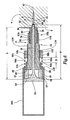
- FIG. 1 is a partially cut-away side sectional view of the fastener driving tool having a first embodiment of a depth control.
- FIG. 2 is a side sectional view of the first embodiment of the depth control of the fastener driving tool (shown without a tool housing) before the tool is actuated.
- FIG. 3 is a side-sectional view of the first embodiment of the depth control (shown without the tool housing) after the fastener driving tool has been actuated, but before a lifting surface has started to lift a depth control probe off a substrate.
- FIG. 4 is a side-sectional view of the first embodiment of the depth control (shown without the tool housing) after the lifting surface has lifted the depth control probe off the substrate.
- FIG. 5 is a side-sectional view of a second embodiment of the depth control (shown without the tool housing) before the fastener driving tool is actuated.
- FIG. 6 is a side-sectional view of the second embodiment of the depth control (shown without the tool housing) in a first predetermined setting after the fastener driving tool has been actuated, shown with a driven fastener.
- FIG. 7 is a side-sectional view of the second embodiment of the depth control (shown without the tool housing) in a second predetermined setting after the fastener driving tool has been actuated, shown with a driven fastener.
- FIG. 8 is a side-sectional view of the second embodiment of the depth control (shown without the tool housing) in a third predetermined setting after the fastener driving tool has been actuated, shown with a driven fastener.
- Referring to FIG. 1, a novel and improved
adjustable depth control 10 for a fastener driving tool 2 is shown.Adjustable depth control 10 uses abumper 46 to stop the forward motion of a driving piston. 12 and exploits the recoil of tool 2 to lift adepth control probe 14 off asubstrate 4 into which afastener 8 is being driven. Fastener driving tool 2 can be one of several types of tools for driving afastener 8 intosubstrate 4, such as a gas combustion powered or powder actuated tool, but a preferred tool 2 is a pneumatically powered tool. - The right side of FIG. 1 is generally referred to as the driving side, because this is the side of tool 2 that
piston 12 is driven towards, and the left side is generally referred to as the trailing side. Similarly, the direction in whichpiston 12 is driven (towards the right in the figures) is generally referred to as the driving direction, while the opposite direction is generally referred to as the trailing direction. However, tool 2 could be operated in several orientations, such as horizontal or vertical, without varying from the scope of the present invention. - Continuing with FIG. 1, tool 2 includes a
housing 18 and atool body 20a for enclosing apiston 12.Tool body 20a is generally cylindrical in shape and has acentral axis 24 running through the length of tool 2.Housing 18 includes ahandle 26 radially extending away fromtool body 20a and atrigger 28 for actuating tool 2. Also included in tool 2 is a magazine (not shown) forfeeding fasteners 8 to tool 2. Tool 2 may also include atrigger probe 34, which prevents tool 2 from being fired unless tool 2 is pushed againstsubstrate 4. - Piston 12 includes a
head 36 and adriving rod 38 for driving afastener 8 into asubstrate 4. Piston 12 is also generally cylindrical in shape and is aligned coaxially withaxis 24 oftool body 20a. Pistonhead 36 includes adriving surface 37, which hitssurface 68 ofbumper 46, as described below. Arepresentative fastener 8, shown in FIG. 2, has ahead 40 at the trailing end offastener 8, apoint 42 at the driving end and ashank 44 axially extending betweenpoint 42 andhead 40. A drivingend 39 ofpiston rod 38 hits atrailing surface 86 offastener head 40 in order to drivefastener 8 into asubstrate 4. As shown in FIG. 2,piston 12 includes an extended length P betweendriving surface 37 ofpiston head 36 and drivingend 39 ofdriving rod 38. - Referring back to FIG. 1, tool 2 includes a
bumper 46 enclosed withintool body 20a. Bumper 46 protectspiston 12 andtool body 20a from damage due to the high forces associated with tool 2.Bumper 46 is associated with the trailingend 56 ofdepth control probe 14 so thatbumper 46 anddepth control probe 14 move together.Bumper 46 can be connected to depth control probe 14 (not shown), orbumper 46 can be retained within a portion ofdepth control probe 14, such as abumper holder 48 integral withdepth control probe 14, orbumper 46 can be adjacent todepth control probe 14.Bumper 46 is also used bydepth control 10 to stop the motion ofpiston 12 in the driving direction when drivingsurface 37 ofpiston head 36hits bumper 46 which stops the driving offastener 8 into substrate, as described below. Tool 2 is designed to stop the driving motion ofpiston 12 withbumper 46 immediately afterpiston 12 has drivenfastener 8 to . the desired depth. -
Bumper 46 may be of any geometrical shape, but should have generally the same cross-sectional shape aspiston 12 andtool body 20a. In one embodiment,bumper 46 has a generally cylindrical shape, with a generally annular cross section so that drivingrod 38 can pass throughbumper 46. -
Bumper 46 may be made of any material that provides some elasticity to absorb shock frompiston 12, is substantially heat resistant to the highest operating temperature created by friction within tool 2 and sufficiently wear resistant so that eachbumper 46 may last for a substantial number of firings of tool 2 between change-outs. Although the material ofbumper 46 should be chosen for its ability to consistently withstand the forces within tool 2, it eventually will wear down. Therefore, it is preferred that the material ofbumper 46 be relatively inexpensive, allowing multiple change-outs to be cost-effective. A preferred material would be a resilient, polymeric plastic or rubber, an example being urethane. - Because tool 2 and
tool body 20a will recoil away fromsubstrate 4 when tool 2 is fired, as shown in FIGS. 1-4, tool 2 is designed so thatdepth control probe 14 will not recoil withtool body 20a, but rather will remain adjacent tosubstrate 4.Bumper 46 is retained by abumper holder 48, which is operationally associated withdepth control 10 so thatbumper 46,bumper holder 48, anddepth control probe 14 move together. - Continuing with FIG. 1,
depth control probe 14 is generally cylindrical in shape and is aligned coaxially withtool body axis 24 and includes a trailingportion 50a, and anadjustable portion 52a.Adjustable portion 52a can be axially adjusted in the driving direction or the trailing direction relative to trailingportion 50a so that an effective length L, shown in FIG. 2, ofdepth control probe 14 andbumper 46 can be chosen in order to control the driving depth offastener 8, as described below.Depth control probe 14 extends axially away fromtool body 20a in the driving direction, as shown in FIG. 1, butdepth control probe 14 is not fixedly connected totool body 20a, as traditional nosepieces and drive probes usually are. Rather,depth control probe 14 can move in the axial direction independently oftool body 20a between an extended position, as shown in FIGS. 1 and 3, to a retracted position, shown in FIG. 2. Becausedepth control probe 14 moves independently fromtool body 20a,depth control probe 14 does not recoil withtool body 20a so thatdepth control probe 14 can consistently and accurately control the driving depth and driving location offastener 8, as described below. Aspring 54a is included in order to biasdepth control probe 14 toward the extended position.Spring 54a also biasesdepth control probe 14 to remain pushed againstsubstrate 4 whiletool body 20a recoils in the trailing direction. -
Bumper holder 48 is connected to a trailingend 56 ofdepth control probe 14 so thatbumper holder 48 is operationally associated withdepth control probe 14 so thatbumper holder 48 moves withdepth control probe 14. In one embodiment, shown in FIG. 2,bumper holder 48 is integrally formed with trailingend 56 of trailingportion 50a ofdepth control probe 14.Bumper holder 48 is generally cylindrical in shape and has acylindrical portion 58 with aflange 60 connected to the driving end ofcylindrical portion 58, whereflange 60 radially extends outwardly from trailingend 56 ofdepth control probe 14 tocylindrical portion 58 ofbumper holder 48 so thatflange 60 is an annulus formed betweendepth control probe 14 andcylindrical portion 58.Flange 60 ofbumper holder 48 includes a leadingsurface 62 on the driving side offlange 60, and a trailing surface 64 for supportingbumper 46. - Turning to FIG. 3, as
piston 12 is driven in the driving direction,tool body 20a moves in the trailing direction due to recoil anddepth control probe 14,bumper holder 48 andbumper 46 remain essentially stationary, with asubstrate contacting surface 66 ofdepth control probe 14 pushed againstsubstrate 4 byspring 54a.Piston 12 moves in the driving direction until drivingsurface 37 ofpiston head 36 eventually hits a trailingsurface 68 ofbumper 46. At this point, drivingend 39 ofpiston 12 has reached a farthest point F relative todepth control probe 14 andpiston 12 cannot move any further in the driving direction because the driving energy inpiston 12 has been dissipated bybumper 46. -
Tool body 20a continues to recoil away from thesubstrate 4, carrying with itpiston 12,bumper 46, anddepth control probe 14, as shown in FIG. 4 and described below. Whenpiston 12 is no longer providing driving energy to drivefastener 8 intosubstrate 4, friction betweensubstrate 4 andshank 44 offastener 8 effectively stopsfastener 8 immediately afterpiston 12 has stopped providing driving energy so thatfastener 8 will not be driven forward any further than it already has been bypiston 12. - A trailing
surface 68 ofbumper 46 remains generally stationary at a predetermined length fromsurface 6 ofsubstrate 4 equal to the effective length L ofdepth control probe 14 so that drivingsurface 37 ofpiston head 36hits bumper 46 at the exact moment that drivingend 39 ofpiston 12 has reached its farthest point F, causingfastener head 40 to be driven to the desired depth. In this way,depth control probe 14 creates a space of a predetermined length betweensubstrate surface 6 andbumper 46 so thatbumper 46 is at a predetermined axial position relative tosubstrate 4. -
Depth control probe 14 includes adepth control adjustment depth control probe 14 to control the driving depth offastener 8, as described below.Depth control probe 14 includes a trailingportion adjustable portion portion adjustable portion portion - In one embodiment, shown in FIGS. 1-4,
depth control adjustment 70a includes anadjustment slot 72 inadjustable portion 52a, a threadedbolt 74 connected to trailingportion 50a, whereinbolt 74 fits intoslot 72, and anut 76 placed onbolt 74.Adjustment slot 72 extends in the axial direction so that whennut 76 is loosened, bolt 74 can slide freely alongslot 72. When a desired effective length L ofdepth control probe 14 is achieved,nut 76 is tightened so that it forcesadjustable portion 52a tight against trailingportion 50a, causing both portions to be locked together so that they move together. An alternative of this embodiment (not shown) is an adjustable slot in trailingportion 50a with the bolt being connected toadjustable portion 52a. This alternative performs the same function of axially adjusting the length L ofdepth control probe 14 and would not vary from the scope of the present invention. - Turning to FIGS. 6-8, another embodiment of
depth control adjustment 70b includes threading 78 on the driving end of trailingportion 50b and corresponding threading 80 included on the trailing end ofadjustable portion 52b, so that one fits radially within the other. The axial length L ofdepth control probe 14 is adjusted by rotatingadjustable portion 52b with respect to trailingportion 50b, which causes adjustable portion threading 80 to engage trailing portion threading 78 so thatadjustable portion 52b moves either in the driving direction or the trailing direction with respect to trailingportion 50b, depending on which directionadjustable portion 52b is rotated. - FIGS. 6-8 show trailing portion threading 78 being on
interior surface 82 of trailingportion 50b and adjustable portion threading 80 being on anexterior surface 84 ofadjustable portion 52b. The diameter of trailing portion threading 78 is slightly larger than the diameter of adjustable portion threading 80 so that adjustable portion threading 80 can be threadingly engaged radially within trailing portion threading 78. - However, an alternative embodiment (not shown) wherein the trailing portion threading is on an exterior surface of the trailing portion while the adjustable portion threading is on an interior surface of the adjustable portion is employed. The diameter of the adjustable portion threading is slightly smaller than the diameter of the trailing portion threading so that the trailing portion threading can be threadingly engaged radially within the adjustable portion threading.
- Continuing with FIGS. 6-8, the relationship between the extended length P of
piston 12 between drivingsurface 37 ofpiston head 36 and drivingend 39 and the effective length L ofdepth control probe 14 determines the driving depth offastener 8.Depth control adjustment 70b can adjust the effective length L ofdepth control probe 14 to at least three predetermined settings. - In a first setting, shown in FIG. 6,
depth control probe 14 is set so thatsubstrate contacting surface 66 is in the trailing direction with respect to drivingend 39 ofpiston 12 at its farthest point F. The effective length L ofdepth control probe 14 in the first setting is shorter than the extended length P ofpiston 12 so that the farthest point F is below, or in the driving direction ofsubstrate surface 6. When the tool is actuated whiledepth control probe 14 is set at the first setting, trailingsurface 86 ofhead 40 will be driven belowsurface 6 ofsubstrate 4 to a distance equal to the difference between length L and extended length P. - FIG. 7 shows a second setting where
substrate contacting surface 66 ofdepth control probe 14 is set so that it is essentially flush with drivingend 39 of drivingrod 38. Whendepth control 14 is set at the second setting, the effective length L ofdepth control probe 14 is essentially equal to the extended length P ofpiston 12 so that the farthest point F is even withsubstrate surface 6. When the tool is actuated whiledepth control probe 14 is in the second setting, a trailingsurface 86 offastener head 40 is flush withsurface 6 ofsubstrate 4. - In a third setting, shown in FIG. 8,
depth control probe 14 extends past drivingend 39 of drivingrod 38 whenpiston 12 is in its fully driven position. When tool 2 is set in the third setting, the effective length L ofdepth control probe 14 is longer than the extended length P ofpiston 12 so that the farthest point F is in the trailing direction ofsubstrate surface 6. Whendepth control probe 14 is set in the third setting, trailingsurface 86 ofhead 40 will stand off above thesurface 6 ofsubstrate 4 at a distance equal to the difference between extended length P and length L. - As shown in FIGS. 6-8,
depth control probe 14 creates a space, either in the trailing or the driving direction, betweensurface 6 ofsubstrate 4 and the farthest point F thatpiston 12 can reach, allowing the position of point F relative tosubstrate surface 6 to be changed. For example, whendepth control adjustment 70b is in its third setting so thatfastener head 40 will stand off fromsurface 6 ofsubstrate 4,depth control probe 14 creates a space betweensurface 6 and tool 2 so that the farthest point F thatpiston driving end 39 can reach is abovesurface 6, as shown in FIG. 8. - Turning back to FIGS. 2 and 5, it has been found that spacing
bumper 46 away fromsubstrate surface 6 by a predetermined length L, and by designing tool 2 so thatbumper 46 does not recoil withtool body depth control 10 of the present invention to effectively and consistently control the driving depth so thatfastener 8 will be driven to the desired depth regardless of the type ofsubstrate 4 being driven into. Surprisingly, this has been found to be true even if tool 2 is being used to drivefastener 8 into a soft andthin substrate 4, such as a piece of plywood as thin as an eighth of an inch. - For some applications it may be desirable to prevent
depth control probe 14 from leaving an impact mark onsubstrate surface 6. In still other applications it may be desirable to leave a controlled and exact impact mark on the substrate surface, such as to leave a distinct design, or "signature mark." The present invention can accurately control the formation of impact marks on the surface of a substrate. This novel feature advantageously uses the recoil created by the tool 2 to liftdepth control probe 14 offsubstrate 4 at a desired moment. - In a pneumatic tool 2, as shown in FIG. 1, compressed air is fed into
cylinder 22. The compressed air exerts a force on bothpiston 12 andtool body 20a, creating a driving force onpiston 12 in the driving direction and a reactive force on thetool body 20a in the trailing direction, where the trailing motion oftool body 20a is commonly referred to as recoil. Becausetool body 20a has a substantially higher mass thanpiston 12,piston 12 will travel in the driving direction much faster thantool body 20a will travel in the trailing direction. In one embodiment, after firing,piston 12 will have traveled about 4 inches in the driving direction whiletool body 20a will have traveled less than about 0.5 inches in the trailing direction. - Referring to FIGS. 2-4, in order to take advantage of the recoil of tool 2 to control impact marks, a lifting
surface 90 is included that uses the recoil motion oftool body 20a to liftdepth control probe 14 offsurface 6 ofsubstrate 4. Liftingsurface 90 faces generally in the trailing direction and is operationally associated withtool body 20a so that whentool body 20a recoils in the trailing direction, liftingsurface 90 also moves in the trailing direction.Depth control 10 also includes arecoil surface 92 that faces generally in the driving direction and is operationally associated withdepth control probe 14 so that whenrecoil surface 92 moves so does depth controlprobe 14. - At some point before tool 2 is actuated, shown in FIG. 2, lifting
surface 90 andrecoil surface 92 are axially spaced apart by a distance D. When tool 2 is fired, recoil causestool body 20a to move in the trailing direction and liftingsurface 90 moves withtool body 20a. Astool body 20a and liftingsurface 90 recoil in the trailing direction,recoil surface 92 is biased byspring 54a to remain essentially stationary. Eventually, the distance D between liftingsurface 90 andrecoil surface 92 is closed by the recoil motion of liftingsurface 90, as in FIG. 3, and liftingsurface 90 engagesrecoil surface 92, liftingdepth control probe 14 offsubstrate 4, as in FIG. 4. - In order to ensure that lifting
surface 90 hits recoilsurface 92, as in FIG. 3, at the desired moment,depth control 10 includes aspacing surface 94a facing generally in the driving direction and a stoppingsurface 96a facing generally towardspacing surface 94a in the trailing direction. Spacingsurface 94a is operationally associated withtool body 20a so that spacingsurface 94a moves whentool body 20a moves, and stoppingsurface 96a is operationally associated withdepth control probe 14 so that stoppingsurface 96a moves whendepth control probe 14 moves. - Turning to FIGS. 3 and 6, a
spacer tool body 20a, as shown in FIGS. 3, or withdepth control probe 14, as shown in FIG. 6. Also,spacer 98a could includespacing surface 94a and not stoppingsurface 96a, as in FIGS. 3, where stoppingsurface 96a is present ondepth control probe 14, orspacer 98b could include stoppingsurface 96b and not spacingsurface 94b, as shown in FIG. 6, wherespacing surface 94b is present ontool body 20b. It is important thatspacing surface surface depth control probe 14 is in the extended position, so that whendepth control probe 14 is pushed againstsubstrate 4,depth control probe 14 moves in the trailing direction relative totool body surface spacing surface recoil surface 92 to be pushed apart from liftingsurface 90 so that therecoil surface 92 and liftingsurface 90 are axially spaced apart by the same distance D. - Turning to FIG. 3, preferably,
spacer 98a includes aspacer adjustment 100a that allows spacer 98a to be axially adjusted so that liftingsurface 90 oftool body 20a hitsrecoil surface 92 at a desired moment in order to control the formation of an impact mark, as described below.Spacer adjustment 100a allows the distance D, described above, to be increased or decreased so that liftingsurface 90 hits recoilsurface 92 at a desired moment afterpiston 12 has been driven. - For example, if it is desired that no impact mark be created on
substrate surface 6,spacer 98a is adjusted so that the distance D between stoppingsurface 96a andspacing surface 94a is short enough so that liftingsurface 90 hits recoilsurface 92 and begins liftingdepth control probe 14 immediately after drivingsurface 37 ofpiston head 36hits bumper 46 and has drivenfastener 8 to the desired depth. Alternatively, if an impact mark is desired, to leave a signature mark,spacer 98a is adjusted so that the distance D is larger than the above case, so that liftingsurface 90 strikes recoilsurface 92 slightly after drivingsurface 37 ofpiston head 36 has hitbumper 46. When drivingsurface 37 ofpiston head 36hits bumper 46 before liftingsurface 90 begins to liftdepth control probe 14 offsubstrate 4, some of the driving energy ofpiston 12 is transferred todepth control probe 14, causing asubstrate contacting surface 66 to be driven intosubstrate 4, leaving an impact mark. - Two embodiments of the present invention are shown in FIGS. 2 through 6 that are exemplary of the exploitation of the recoil motion of
tool body depth control probe 14 offsubstrate 4. In one embodiment ofdepth control 10, shown in FIGS. 1-4,tool body 20a includes anosepiece 102 connected to, and aligned coaxially withtool body 20a and axially extending in the driving direction away fromtool body 20a, wherenosepiece 102 guidespiston rod 38 andfastener 8 aspiston 12 is driven in the driving direction.Flange 60 ofbumper holder 48 includesrecoil surface 92 on the driving side offlange 60, andtool body 20a includes an annularinterior surface 90 withincylinder 22 that corresponds to recoil surface ofbumper holder 48. Aninterior surface 90 oftool body 20a faces generally in the trailing direction and acts as liftingsurface 90. Liftingsurface 90 oftool body 20a is on the driving side offlange 60 so that it will recoil intorecoil surface 92 to liftbumper holder 48, and thereforedepth control probe 14 in the trailing direction. - Before tool 2 is used, shown in FIG. 1,
depth control probe 14 is in an extended position relative totool body 20a withrecoil surface 92 offlange 60 being abutted against liftingsurface 90.Depth control probe 14 is connected tobumper holder 48 so thatdepth control probe 14 axially extends in the driving direction towardsubstrate 4. Neitherdepth control probe 14 norbumper holder 48 are connected totool body 20a, so that they both can move axially with respect totool body 20a. - As shown in FIGS. 2-4,
spacer 98a is coupled to the driving end oftool body 20a so thatspacer 98a extends axially in the driving direction away fromtool body 20a towardssubstrate 4. Spacingsurface 94a is located on the driving end ofspacer 98a and stoppingsurface 96a is located on the trailing end of a portion ofdepth control probe 14, as shown in FIG. 2.Spacer 98a extends away fromtool body 20a in the driving direction to a distance that is less than the distancedepth control probe 14 extends frombumper holder 48 so that a space of distance D is created betweenspacer 98a anddepth control probe 14. - When
depth control probe 14 is pressed againstsubstrate 4, as shown in FIG. 2,tool body 20a is pushed in the driving direction so thatdepth control probe 14 is pushed into the retracted position wherein stoppingsurface 96a is pushed againstspacing surface 94a. When this happens,recoil surface 92 onbumper holder 48 is separated from liftingsurface 90 ontool body 20a whilebumper holder 48 remains essentially stationary so that a space having the same distance D is created betweenrecoil surface 92 ofbumper holder 48 and liftingsurface 90 oftool body 20a. - At this point, tool 2 can be actuated so that
piston 12 is driven in the driving direction, shown in FIG. 3. Aspiston 12 moves in the driving direction, it drivesfastener 8 intosubstrate 4. As described above,tool body 20a recoils in the trailing direction, while aspring 54a placed betweenspacer 98a anddepth control probe 14 acts to biasdepth control probe 14 towardssubstrate 4 to ensure thatdepth control probe 14 andbumper 46 do not recoil withtool body 20a, but rather remain pushed againstsubstrate 4. Eventually, drivingsurface 37 ofpiston head 36hits bumper 46 whenpiston 12 has drivenfastener 8 to the desired driving depth. Astool body 20a recoils in the trailing direction, liftingsurface 90 eventually hitsrecoil surface 92 onbumper holder 48 to liftdepth control probe 14 offsubstrate surface 6. - Preferably,
spacer 98a includes aspacer adjustment 100a, shown in FIGS. 3 and 4, that allows the length ofspacer 98a to be axially adjusted so that the moment when liftingsurface 90 oftool body 20a hitsrecoil surface 92 ofbumper holder 48 can be controlled, depending on whether an impact mark is desired or not.Spacer adjustment 100a includes an axially extendingadjustment slot 104, abolt 106 and anut 108. Whennut 108 is loosened, bolt 106 can freely slide alongslot 104 until it reaches a desired location.Nut 108 can then be tightened to lockspacer adjustment 100a in place. - Even after hitting
bumper holder 48, as in FIG. 3,tool body 20a still has sufficient momentum to continue moving in the trailing direction. When this happens, liftingsurface 90 carriesbumper holder 48 anddepth control probe 14 with it so that substrate contacting surface 66a ofdepth control probe 14 is lifted offsurface 6 ofsubstrate 4, as shown in FIG. 4. As described above, trailingsurface 68 ofbumper 46 is also in contact with drivingsurface 37 ofpiston head 36 so thatpiston 12 is also lifted away fromsurface 6 ofsubstrate 4. - Another embodiment of
depth control 10 is shown in FIGS. 5-8. In this embodiment, no nosepiece is present withtool body 20b, andpiston rod 38 is guided bydepth control probe 14.Flange 60 ofbumper holder 48 still includesrecoil surface 92, andinterior surface 90 oftool body 20b still acts as liftingsurface 90, howeverspacer 98b is associated withdepth control probe 14, rather than the tool body. - Turning to FIG. 6,
spacer 98b is threadingly engaged with anexterior surface 110 ofdepth control probe 14.Spacer 98b is generally annular in shape and includes spacer threading 112 on aninterior surface 114.Exterior surface 110 ofdepth control probe 14 also includes threading 116 that corresponds to spacer threading 112.Spacer 98b is axially adjusted by rotatingspacer 98b relative todepth control probe 14 so that spacer threading 112 engages threading 116 ondepth control probe 14 so thatspacer 98b moves in the driving direction or the trailing direction depending on whichdirection spacer 98b is rotated. Stoppingsurface 96b is located on the trailing side ofspacer 98b, corresponding to spacingsurface 94b located on the driving end oftool body 20b. - When tool 2 is not in operation, a
spring 54b biasesdepth control probe 14 into its extended position by acting between a leading surface 118b oftool body 20b and stoppingsurface 96b onspacer 98b, which causesrecoil surface 92 to be biased toward liftingsurface 90. As shown in FIG. 6, stoppingsurface 96b andspacing surface 94b are axially spaced by a distance of D. - Returning to FIG. 3,
substrate contacting surface 66 is pushed againstsubstrate 4 so thattool body 20b is pushed in the driving direction so thatdepth control probe 14 is in its retracted position where stoppingsurface 96b is in contact withspacing surface 94b, as shown in FIG. 5, creating a gap betweenrecoil surface 92 and liftingsurface 90 having the same distance D. - When tool 2 is actuated,
piston 12 is driven in the driving direction andtool body 20b recoils in the trailing direction whilespring 54b biasesdepth control probe 14 to remain againstsubstrate 4. Eventually the gap between liftingsurface 90 andrecoil surface 92 will be closed and liftingsurface 90 will come into contact withrecoil surface 92, as in FIG. 6.Tool body 20b still contains sufficient momentum to continue moving in the trailing direction so that liftingsurface 90 engagesrecoil surface 92 to liftdepth control probe 14 offsubstrate 4. - The method by which
adjustable depth control 10 controls the driving depth offastener 8 insubstrate 4 includes the steps of pushingdepth control probe 14 againstsurface 6 ofsubstrate 4 so thatdepth control probe 14 is in the retracted position, firing tool 2 so thatpiston 12 is driven in the driving direction, driving afastener 8 in the driving direction withpiston 12, and hitting trailingsurface 68 ofbumper 46 withpiston 12 so that the motion ofpiston 12 in the driving direction is stopped bybumper 46. - As shown in FIG. 5, pushing
substrate contacting surface 66 ofdepth control probe 14 againstsurface 6 ofsubstrate 4forces tool body 20b in the driving direction. Because spacingsurface 94b is operationally associated withtool body 20b, it moves in the driving direction as well until spacingsurface 94b is pushed into stoppingsurface 96b. When stoppingsurface 96b comes into contact withspacing surface 94b, the motion oftool body 20b in the driving direction is stopped. Liftingsurface 90 also moves in the driving direction untiltool body 20b stops. At this point,recoil surface 92 has been axially spaced away from liftingsurface 90 by a distance D due to the motion in the driving direction oftool body 20b. - Firing fastener driving tool 2, as shown in FIG. 6, causes
piston 12 to be driven in the driving direction and causestool body 20b to recoil in the trailing direction.Piston 12 andfastener 8 are guided in the driving direction bydepth control probe 14 towardsubstrate 4.Tool body 20b recoils and the distance D between liftingsurface 90 andrecoil surface 92 is closed so thatdepth control probe 14 changes from the retracted position, shown in FIG. 5, to the extended position, shown in FIG. 6, relative totool body 20b. - Lifting
surface 90 is operationally associated withtool body 20b so liftingsurface 90 is also recoiled in the trailing direction until lifting surface hits recoilsurface 92.Tool body 20b and liftingsurface 90 continue to move in the trailing direction, causing a lifting ofdepth control probe 14 to occur because liftingsurface 90 lifts recoilsurface 92, and whenrecoil surface 92 moves, so does depth controlprobe 14. A completed lifting step is shown in FIG. 6. - As described above, and shown in FIG. 6, driving
surface 37 ofpiston head 36hits bumper 46, stopping the driving motion ofpiston 12, and stopping the driving offastener 8 intosubstrate 4.Depth control probe 14 creates a space having a predetermined length L betweensubstrate surface 6 and trailingsurface 68 ofbumper 46 at trailingend 56.Depth control adjustment 70b allows the effective length L ofdepth control probe 14 to be changed so that the predetermined length L of the space betweensubstrate surface 6 and trailingsurface 68 ofbumper 46 can be adjusted axially. Adjusting the predetermined length is accomplished by axially adjustingadjustable portion 52b with respect to trailingportion 50b ofdepth control probe 14. - The depth of drive control of the present invention advantageously combines an improved method of controlling the driving depth of a fastener into a substrate with a method of lifting the depth control probe off the surface of the substrate. The inventive depth of drive control exploits the tool's own recoil to provide to lift the tool off the surface of the substrate, effectively controlling the formation of an impact mark on the surface of the substrate.
- The present invention is not limited to the above-described embodiments, but should be limited solely by the following claims.
- The features of the description, the claims and the drawings, single or in any combination, are patentable, as far as not excluded by the prior art. Each claim can depend on any one or more of the other claims.
Claims (28)
- A fastener driving tool for axially driving a fastener, comprising:a tool body having a cylinder with an axis, the cylinder enclosing a piston,wherein the piston is driven in a driving direction; and
a depth control probe;
a bumper associated with the depth control probe, the bumper having a trailing surface;
wherein the depth control probe is movable relative to the tool body between an extended position and a retracted position;
wherein the depth control probe creates a space having a predetermined length between a surface of a substrate and the trailing surface of the bumper; and
wherein a surface of the piston hits the trailing surface of the bumper after the fastener is driven. - A fastener driving tool according to claim 1, further comprising a lifting surface operationally associated with the tool body and a recoil surface operationally associated with the depth control probe, wherein the recoil surface is spaced away from the lifting surface when the depth control probe is in the retracted position, and wherein the lifting surface is proximate the recoil surface when the depth control probe is in the extended position.
- A fastener driving tool according to claim 2, wherein the recoil surface is associated with a trailing end of the depth control probe.
- A fastener driving tool according to claim 2, wherein the lifting surface is in contact with the recoil surface with the depth control probe is in the second position.
- A fastener driving tool according to claim 2, wherein there is a gap having a predetermined distance between the recoil surface and the lifting surface when the depth control probe is in the retracted position.
- A fastener driving tool according to claim 5, further comprising a spacing surface operationally associated with the tool body and a stopping surface operationally associated with the depth control probe, wherein the stopping surface is in contact with the spacing surface when the depth control probe is in the retracted position and wherein there is a gap having the predetermined distance between the stopping surface and the spacing surface when the depth control probe is in the extended position.
- A fastener driving tool according to claim 2, wherein the lifting surface faces generally away from the driving direction.
- A fastener driving tool according to claim 2, wherein the recoil surface faces generally in the driving direction.
- A fastener driving tool according to claim 2, wherein a portion of the depth control probe is radially spaced inside a portion of the tool body, and wherein the lifting surface is on a radially inwardly extending shoulder of the tool body and the recoil surface is on a radially outwardly extending flange of the depth control probe.
- A fastener driving tool according to claim 2, wherein the tool body moves in a direction generally opposite the driving direction after the fastener driving tool has been actuated.
- A fastener driving tool according to claim 10, wherein the tool body moves so that the depth control probe changes from the retracted position to the extended position, and wherein the depth control probe remains generally stationary and guides a fastener while the tool body moves between the retracted and extended position.
- A fastener driving tool according to claim 10, wherein the tool body moves so that the depth control probe changes from the retracted position to the extended position so that the lifting surface contacts the recoil surface and lifts the depth control probe off the substrate.
- A fastener driving tool according to claim 1, wherein a portion of the depth control probe is axially adjustable with respect to the tool body.
- A fastener driving tool according to claim 1, wherein the depth control probe includes a substrate contacting surface, and wherein the depth control probe is in the retracted position when the substrate contacting surface is pushed against a substrate.
- A fastener driving tool for axially driving a fastener, comprising:a tool body having a cylinder with an axis, the cylinder enclosing a bumper and a piston, wherein the piston is driven in a driving direction;wherein the tool body includes a lifting surface;
a depth control probe having a substrate contacting surface, and a recoil surface;
wherein the depth control probe is movable with respect to the tool body between a retracted position and an extended position;
wherein the recoil surface is spaced away from the lifting surface and the substrate contacting surface is in contact with a substrate when the depth control probe is in the retracted position; and
wherein the lifting surface is in contact with the recoil surface, the substrate contacting surface is not in contact with the substrate, and the bumper is in contact with the piston when the depth control probe is in the extended position. - A method of controlling the driving depth of a fastener driving tool, comprising:providing a fastener driving tool having a tool body with an axis, the tool body enclosing a piston, a depth control probe, a bumper associated with the depth control probe, the bumper having a trailing surface, wherein the depth control probe is movable with respect to the tool body, and wherein the depth control probe creates a space of a predetermined length between a surface of a substrate and the trailing surface of the bumper;pushing the depth control probe against the surface of the substrate;firing the tool so that the piston is driven in a driving direction;driving a fastener in the driving direction with the piston; andhitting the trailing surface of the bumper with the piston so that the piston is no longer moving in the driving direction.
- A method according to claim 16, wherein the piston includes a driving end and a piston surface, the piston having an extended length between the driving end and the piston surface.
- A method according to claim 17, wherein the extended length of the piston is shorter than the predetermined length so that a head of the fastener is driven to a depth above the surface of the substrate equal to a difference the extended length of the piston and the predetermined length.
- A method according to claim 17, wherein the extended length of the piston is generally equal to the predetermined length so that a head of the fastener is driven to a depth that is substantially flush with the surface of the substrate.
- A method according to claim 17, wherein the extended length of the piston is longer than the predetermined length so that a head of the fastener is driven to a depth below the surface of the substrate equal to a difference between the extended length of the piston and the predetermined length.
- A method according to claim 16, further comprising the step of adjusting the predetermined length.
- A method according to claim 16, wherein the tool includes a recoil surface operationally associated with the depth control probe and a lifting surface operationally associated with the tool body.
- A method according to claim 22, further comprising the step of recoiling the tool body so that the lifting surface comes into contact with the recoil surface.
- A method according to claim 23, wherein the tool body recoils for a predetermined distance before the lifting surface comes into contact with the recoil surface, further comprising the step of adjusting the predetermined distance.
- A method according to claim 22, further comprising the step of lifting the depth control probe off the substrate with the lifting surface.
- A method according to claim 25, wherein the lifting step does not occur until a fastener has been driven to a predetermined depth by the piston.
- A method according to claim 22, wherein the recoil surface is spaced from the lifting surface by a predetermined distance during the pushing step, further comprising the step of adjusting the predetermined distance.
- A method according to claim 16, wherein the fastener driving tool further comprises a spacing surface operationally associated with the tool body and a stopping surface operationally associated with the depth control probe, and wherein the pushing step includes the stopping surface being pushed into the spacing surface.
Applications Claiming Priority (2)
| Application Number | Priority Date | Filing Date | Title |
|---|---|---|---|
| US261022 | 2002-09-30 | ||
| US10/261,022 US6695192B1 (en) | 2002-09-30 | 2002-09-30 | Adjustable depth control for fastener driving tool |
Publications (2)
| Publication Number | Publication Date |
|---|---|
| EP1403005A1 true EP1403005A1 (en) | 2004-03-31 |
| EP1403005B1 EP1403005B1 (en) | 2011-06-01 |
Family
ID=31495468
Family Applications (1)
| Application Number | Title | Priority Date | Filing Date |
|---|---|---|---|
| EP03019710A Expired - Lifetime EP1403005B1 (en) | 2002-09-30 | 2003-08-29 | Fastener driving tool with adjustable depth control and method |
Country Status (7)
| Country | Link |
|---|---|
| US (1) | US6695192B1 (en) |
| EP (1) | EP1403005B1 (en) |
| AT (1) | ATE511430T1 (en) |
| AU (1) | AU2003244531B2 (en) |
| CA (1) | CA2443185C (en) |
| ES (1) | ES2366213T3 (en) |
| NZ (1) | NZ528408A (en) |
Cited By (2)
| Publication number | Priority date | Publication date | Assignee | Title |
|---|---|---|---|---|
| CN102229135A (en) * | 2011-06-25 | 2011-11-02 | 林岳洪 | Pneumatic nail gun |
| CN113195168A (en) * | 2018-12-20 | 2021-07-30 | 喜利得股份公司 | Drive device |
Families Citing this family (35)
| Publication number | Priority date | Publication date | Assignee | Title |
|---|---|---|---|---|
| US20020125294A1 (en) * | 2001-01-09 | 2002-09-12 | Building Materials Investment Corporation | Nail gun spacer |
| US6865806B2 (en) * | 2002-08-01 | 2005-03-15 | International Engine Intellectual Property Company, Llc | Core element fastening and assembly method |
| JP4239731B2 (en) * | 2003-07-04 | 2009-03-18 | マックス株式会社 | Contact mechanism of power driven nailer |
| US6866177B1 (en) * | 2003-08-29 | 2005-03-15 | Panrex Industrial Co., Ltd. | Depth control device for a fastener driving tool |
| FR2869280B1 (en) * | 2004-04-26 | 2008-02-15 | Valeo Systemes Dessuyage | WIPER MECHANISM CONNECTOR FOR THE SIDE MOUNTING OF THE END OF AN ARM ON A WIPER BLADE |
| DE102004044156A1 (en) * | 2004-09-13 | 2006-03-16 | Hilti Ag | setting tool |
| US7055729B2 (en) * | 2004-09-24 | 2006-06-06 | Illinois Tool Works Inc. | Tool-free depth-of-drive adjustment for a fastener-driving tool |
| US7612153B2 (en) * | 2004-10-25 | 2009-11-03 | Intezyne Technologies, Inc. | Heterobifunctional poly(ethylene glycol) and uses thereof |
| US7341172B2 (en) | 2005-09-15 | 2008-03-11 | Illinois Tool Works Inc. | Tool-less rotatable depth adjustment for fastener-driving tool |
| US7318546B2 (en) * | 2005-10-24 | 2008-01-15 | Illinois Tool Works Inc. | Adjustable depth-of-drive mechanism for a fastener driving tool |
| DE102006000025A1 (en) * | 2006-01-25 | 2007-07-26 | Hilti Ag | setting tool |
| TW200732103A (en) * | 2006-02-24 | 2007-09-01 | Basso Ind Corp | Striking nail depth control structure of palm hammer |
| US7299961B2 (en) * | 2006-03-02 | 2007-11-27 | The Boeing Company | Device for controlled depth riveting |
| US8104659B2 (en) * | 2006-03-27 | 2012-01-31 | Stanley Black & Decker, Inc. | Electromagnetic stapler with a manually adjustable depth adjuster |
| US20070278276A1 (en) * | 2006-06-05 | 2007-12-06 | Wan-Fu Wen | Nailing Tool with Displacable Discharge Tube |
| US7513404B2 (en) | 2007-04-13 | 2009-04-07 | Illinois Tool Works Inc. | Depth of drive control with load transfer for fastener driver |
| US20080290132A1 (en) * | 2007-05-24 | 2008-11-27 | Chia-Sheng Liang | Main Air Valve for Pneumatic Nail Gun |
| US20090166394A1 (en) * | 2008-01-02 | 2009-07-02 | Lawrence Gyorkos | External Nailing Device Adaptor |
| US20090206121A1 (en) * | 2008-02-14 | 2009-08-20 | Araiza Frank L | Power adjustable fastener propelling tool |
| US7975777B2 (en) * | 2008-12-19 | 2011-07-12 | Robert Bosch Gmbh | Cellular foam bumper for nailer |
| JP5428585B2 (en) * | 2009-07-01 | 2014-02-26 | 日立工機株式会社 | Driving machine |
| US8840002B2 (en) * | 2009-07-01 | 2014-09-23 | Hitachi Koki Co., Ltd. | Fastener-driving tool |
| JP5344245B2 (en) * | 2009-09-28 | 2013-11-20 | 日立工機株式会社 | Driving machine |
| DE102010063176A1 (en) * | 2010-12-15 | 2012-06-21 | Hilti Aktiengesellschaft | Electrically operated bolt gun |
| US9402743B2 (en) | 2013-09-25 | 2016-08-02 | Depuy Mitek, Llc | Medical implant driver with depth-limiting feature |
| CN208289826U (en) | 2015-02-06 | 2018-12-28 | 米沃奇电动工具公司 | Using gas spring as the fastener driver of power |
| USD787290S1 (en) | 2016-02-10 | 2017-05-23 | Illinois Tool Works Inc. | Pneumatic nailer |
| US10668608B2 (en) | 2016-02-10 | 2020-06-02 | Illinois Tool Works Inc. | Fastener driving tool |
| USD843192S1 (en) * | 2017-02-10 | 2019-03-19 | Philip M. Reed | Nailer adapter for siding |
| JP7271438B2 (en) | 2017-05-03 | 2023-05-11 | シグノード インダストリアル グループ リミティド ライアビリティ カンパニー | electric stapling device |
| USD854820S1 (en) | 2017-11-14 | 2019-07-30 | Illinois Tool Works Inc. | Fastener driving tool belt hook |
| US10926391B2 (en) | 2017-11-14 | 2021-02-23 | Illinois Tool Works Inc. | Powered fastener driving tool having hook assemblies |
| USD855431S1 (en) | 2017-11-14 | 2019-08-06 | Illinois Tool Works Inc. | Fastener driving tool pipe hook |
| US11192226B2 (en) * | 2018-07-31 | 2021-12-07 | Chicago Display Marketing Company | Fastener carrier with depth limiter |
| US10926389B2 (en) * | 2018-07-31 | 2021-02-23 | Chung-Heng Lee | Powder-actuated tool |
Citations (5)
| Publication number | Priority date | Publication date | Assignee | Title |
|---|---|---|---|---|
| US3399817A (en) * | 1964-09-07 | 1968-09-03 | Bauer Carl | Devices for driving pins into masonry, structural members or the like |
| US3659768A (en) * | 1970-06-12 | 1972-05-02 | Olin Corp | Fastener driving tool |
| FR2268601A2 (en) * | 1974-04-29 | 1975-11-21 | Sasse | Barrel for nail driving pistol - has interchangeable nail guides in sleeve in end with piston stop ring |
| US4711385A (en) * | 1985-11-19 | 1987-12-08 | Hilti Aktiengesellschaft | Explosive powder charge actuated fastening element driving device |
| US5261587A (en) * | 1993-01-04 | 1993-11-16 | Illinois Tool Works Inc. | Fastener-driving tool with improved, adjustable, tool-actuating structures |
Family Cites Families (24)
| Publication number | Priority date | Publication date | Assignee | Title |
|---|---|---|---|---|
| US3572572A (en) * | 1969-07-22 | 1971-03-30 | Textron Inc | Fluid pressure operated fastener driving device |
| US4867366A (en) * | 1984-10-26 | 1989-09-19 | Kleinholz Edward O | Pneumatic fastener-driving tool and method |
| US4767043A (en) | 1987-07-06 | 1988-08-30 | Stanley-Bostitch, Inc. | Fastener driving device with improved countersink adjusting mechanism |
| US5263626A (en) * | 1992-12-29 | 1993-11-23 | Illinois Tool Works Inc. | Fastener-driving tool with actuating structure biased by dual biasing means |
| US5320268A (en) * | 1993-04-13 | 1994-06-14 | Illinois Tool Works Inc. | Powered dimple-forming and fastener-driving tool |
| US5385286A (en) | 1994-01-07 | 1995-01-31 | Senco Products, Inc. | Adjustable depth control for use with a fastener driving tool |
| JP3243927B2 (en) | 1994-04-15 | 2002-01-07 | 日立工機株式会社 | Driving depth adjusting device for driving machine |
| US5564614A (en) | 1995-06-15 | 1996-10-15 | Testo Industry Corp. | Nailing depth adjusting mechanism for pneumatic nail guns |
| US5785227A (en) | 1995-11-10 | 1998-07-28 | Hitachi Koki Co., Ltd. | Adjustment mechanism for adjusting depth at which pneumatic nailing machine drives nails into workpiece |
| US5579977A (en) | 1996-01-16 | 1996-12-03 | Yang; Peter | Adjusting and positioning mechanism for nailing guns |
| US5799855A (en) | 1996-02-09 | 1998-09-01 | Illinois Tool Works Inc. | Velocity control and nosepiece stabilizer system for combustion powered tools |
| US5685473A (en) | 1996-06-07 | 1997-11-11 | Illinois Tool Works Inc. | Fastener-driving tool having adjustable controlling mechanism |
| US5743455A (en) | 1996-06-21 | 1998-04-28 | Holliday; Brett | Adapter for fastener driving tool and method thereof |
| TW321049U (en) | 1997-04-25 | 1997-11-21 | Basso Ind Corp | Adjustable safety device improvement of nailing machine |
| US5839638A (en) | 1997-06-26 | 1998-11-24 | Illinois Tool Works Inc | Pneumatic trim nailer |
| US5909836A (en) * | 1997-10-31 | 1999-06-08 | Illinois Tool Works Inc. | Combustion powered tool with combustion chamber lockout |
| FR2774017B1 (en) | 1998-01-27 | 2000-03-17 | Spit Soc Prospect Inv Techn | COMPRESSED GAS-PISTON FIXING APPARATUS |
| US6012622A (en) | 1998-04-20 | 2000-01-11 | Illinois Tool Works Inc. | Fastener driving tool for trim applications |
| JP3626011B2 (en) * | 1998-05-11 | 2005-03-02 | 株式会社マキタ | Nailing machine |
| US5988477A (en) * | 1998-06-03 | 1999-11-23 | Illinois Tools Works, Inc. | Nosepiece shield for combustion powered tool |
| US6186386B1 (en) | 1999-08-06 | 2001-02-13 | Stanley Fastening Systems, Lp | Fastener driving device with enhanced depth adjusting assembly |
| US6170729B1 (en) | 2000-06-28 | 2001-01-09 | Basso Industry Corp. | Nailing depth adjusting device for a power nailer |
| US6988648B2 (en) | 2001-03-01 | 2006-01-24 | Illinois Tool Works Inc. | Adjustable depth of drive device |
| US6427896B1 (en) | 2002-01-25 | 2002-08-06 | Roman Ho | Safety device for pneumatic nailers |
-
2002
- 2002-09-30 US US10/261,022 patent/US6695192B1/en not_active Expired - Lifetime
-
2003
- 2003-08-29 ES ES03019710T patent/ES2366213T3/en not_active Expired - Lifetime
- 2003-08-29 AT AT03019710T patent/ATE511430T1/en not_active IP Right Cessation
- 2003-08-29 EP EP03019710A patent/EP1403005B1/en not_active Expired - Lifetime
- 2003-09-03 AU AU2003244531A patent/AU2003244531B2/en not_active Ceased
- 2003-09-23 NZ NZ528408A patent/NZ528408A/en not_active IP Right Cessation
- 2003-09-29 CA CA002443185A patent/CA2443185C/en not_active Expired - Fee Related
Patent Citations (5)
| Publication number | Priority date | Publication date | Assignee | Title |
|---|---|---|---|---|
| US3399817A (en) * | 1964-09-07 | 1968-09-03 | Bauer Carl | Devices for driving pins into masonry, structural members or the like |
| US3659768A (en) * | 1970-06-12 | 1972-05-02 | Olin Corp | Fastener driving tool |
| FR2268601A2 (en) * | 1974-04-29 | 1975-11-21 | Sasse | Barrel for nail driving pistol - has interchangeable nail guides in sleeve in end with piston stop ring |
| US4711385A (en) * | 1985-11-19 | 1987-12-08 | Hilti Aktiengesellschaft | Explosive powder charge actuated fastening element driving device |
| US5261587A (en) * | 1993-01-04 | 1993-11-16 | Illinois Tool Works Inc. | Fastener-driving tool with improved, adjustable, tool-actuating structures |
Cited By (3)
| Publication number | Priority date | Publication date | Assignee | Title |
|---|---|---|---|---|
| CN102229135A (en) * | 2011-06-25 | 2011-11-02 | 林岳洪 | Pneumatic nail gun |
| CN102229135B (en) * | 2011-06-25 | 2013-10-16 | 广东明晖气动科技有限公司 | Pneumatic nail gun |
| CN113195168A (en) * | 2018-12-20 | 2021-07-30 | 喜利得股份公司 | Drive device |
Also Published As
| Publication number | Publication date |
|---|---|
| ES2366213T3 (en) | 2011-10-18 |
| EP1403005B1 (en) | 2011-06-01 |
| NZ528408A (en) | 2004-06-25 |
| AU2003244531A1 (en) | 2004-04-22 |
| ATE511430T1 (en) | 2011-06-15 |
| CA2443185C (en) | 2007-09-25 |
| CA2443185A1 (en) | 2004-03-30 |
| AU2003244531B2 (en) | 2005-05-19 |
| US6695192B1 (en) | 2004-02-24 |
Similar Documents
| Publication | Publication Date | Title |
|---|---|---|
| EP1403005B1 (en) | Fastener driving tool with adjustable depth control and method | |
| AU2003204262B2 (en) | Framing tool with automatic fastener-size adjustment | |
| CA1298931C (en) | Guide for fastener driving tool | |
| EP2944426B1 (en) | Nailer driver blade stop | |
| EP0726122B1 (en) | Combustion-powered, fastener-driving tool with gas-actuated, fastener-feeding mechanism | |
| CA2500591C (en) | Improved nail placement device | |
| US5261587A (en) | Fastener-driving tool with improved, adjustable, tool-actuating structures | |
| EP1813394B1 (en) | Combustion chamber control for combustion-powered fastener-driving tool | |
| CA2119526C (en) | Powered dimple-forming and fastener-driving tool | |
| CA2694967C (en) | Actuator pin guide for a fastener driving tool | |
| US5205457A (en) | Driving tool and method | |
| KR0140043B1 (en) | Hammer blow gunpowder nailing tool | |
| CN1134126A (en) | Compression actuated tool driving fasteners | |
| CA2681207C (en) | Nose assembly for a fastener driving tool | |
| WO2000016947A1 (en) | Multi-stroke fastening device | |
| JPH03111179A (en) | Trigger mechanism for fastener driving machine |
Legal Events
| Date | Code | Title | Description |
|---|---|---|---|
| PUAI | Public reference made under article 153(3) epc to a published international application that has entered the european phase |
Free format text: ORIGINAL CODE: 0009012 |
|
| AK | Designated contracting states |
Kind code of ref document: A1 Designated state(s): AT BE BG CH CY CZ DE DK EE ES FI FR GB GR HU IE IT LI LU MC NL PT RO SE SI SK TR |
|
| AX | Request for extension of the european patent |
Extension state: AL LT LV MK |
|
| 17P | Request for examination filed |
Effective date: 20040823 |
|
| AKX | Designation fees paid |
Designated state(s): AT BE BG CH CY CZ DE DK EE ES FI FR GB GR HU IE IT LI LU MC NL PT RO SE SI SK TR |
|
| 17Q | First examination report despatched |
Effective date: 20041125 |
|
| GRAP | Despatch of communication of intention to grant a patent |
Free format text: ORIGINAL CODE: EPIDOSNIGR1 |
|
| RTI1 | Title (correction) |
Free format text: FASTENER DRIVING TOOL WITH ADJUSTABLE DEPTH CONTROL AND METHOD |
|
| GRAS | Grant fee paid |
Free format text: ORIGINAL CODE: EPIDOSNIGR3 |
|
| GRAA | (expected) grant |
Free format text: ORIGINAL CODE: 0009210 |
|
| AK | Designated contracting states |
Kind code of ref document: B1 Designated state(s): AT BE BG CH CY CZ DE DK EE ES FI FR GB GR HU IE IT LI LU MC NL PT RO SE SI SK TR |
|
| REG | Reference to a national code |
Ref country code: GB Ref legal event code: FG4D |
|
| REG | Reference to a national code |
Ref country code: CH Ref legal event code: EP |
|
| REG | Reference to a national code |
Ref country code: IE Ref legal event code: FG4D |
|
| REG | Reference to a national code |
Ref country code: DE Ref legal event code: R096 Ref document number: 60337270 Country of ref document: DE Effective date: 20110714 |
|
| REG | Reference to a national code |
Ref country code: NL Ref legal event code: VDEP Effective date: 20110601 |
|
| REG | Reference to a national code |
Ref country code: ES Ref legal event code: FG2A Ref document number: 2366213 Country of ref document: ES Kind code of ref document: T3 Effective date: 20111018 |
|
| PG25 | Lapsed in a contracting state [announced via postgrant information from national office to epo] |
Ref country code: SE Free format text: LAPSE BECAUSE OF FAILURE TO SUBMIT A TRANSLATION OF THE DESCRIPTION OR TO PAY THE FEE WITHIN THE PRESCRIBED TIME-LIMIT Effective date: 20110601 |
|
| PG25 | Lapsed in a contracting state [announced via postgrant information from national office to epo] |
Ref country code: AT Free format text: LAPSE BECAUSE OF FAILURE TO SUBMIT A TRANSLATION OF THE DESCRIPTION OR TO PAY THE FEE WITHIN THE PRESCRIBED TIME-LIMIT Effective date: 20110601 Ref country code: GR Free format text: LAPSE BECAUSE OF FAILURE TO SUBMIT A TRANSLATION OF THE DESCRIPTION OR TO PAY THE FEE WITHIN THE PRESCRIBED TIME-LIMIT Effective date: 20110902 Ref country code: CY Free format text: LAPSE BECAUSE OF FAILURE TO SUBMIT A TRANSLATION OF THE DESCRIPTION OR TO PAY THE FEE WITHIN THE PRESCRIBED TIME-LIMIT Effective date: 20110601 Ref country code: SI Free format text: LAPSE BECAUSE OF FAILURE TO SUBMIT A TRANSLATION OF THE DESCRIPTION OR TO PAY THE FEE WITHIN THE PRESCRIBED TIME-LIMIT Effective date: 20110601 Ref country code: FI Free format text: LAPSE BECAUSE OF FAILURE TO SUBMIT A TRANSLATION OF THE DESCRIPTION OR TO PAY THE FEE WITHIN THE PRESCRIBED TIME-LIMIT Effective date: 20110601 |
|
| PGFP | Annual fee paid to national office [announced via postgrant information from national office to epo] |
Ref country code: ES Payment date: 20110826 Year of fee payment: 9 |
|
| PG25 | Lapsed in a contracting state [announced via postgrant information from national office to epo] |
Ref country code: NL Free format text: LAPSE BECAUSE OF FAILURE TO SUBMIT A TRANSLATION OF THE DESCRIPTION OR TO PAY THE FEE WITHIN THE PRESCRIBED TIME-LIMIT Effective date: 20110601 Ref country code: BE Free format text: LAPSE BECAUSE OF FAILURE TO SUBMIT A TRANSLATION OF THE DESCRIPTION OR TO PAY THE FEE WITHIN THE PRESCRIBED TIME-LIMIT Effective date: 20110601 |
|
| PG25 | Lapsed in a contracting state [announced via postgrant information from national office to epo] |
Ref country code: EE Free format text: LAPSE BECAUSE OF FAILURE TO SUBMIT A TRANSLATION OF THE DESCRIPTION OR TO PAY THE FEE WITHIN THE PRESCRIBED TIME-LIMIT Effective date: 20110601 Ref country code: CZ Free format text: LAPSE BECAUSE OF FAILURE TO SUBMIT A TRANSLATION OF THE DESCRIPTION OR TO PAY THE FEE WITHIN THE PRESCRIBED TIME-LIMIT Effective date: 20110601 Ref country code: PT Free format text: LAPSE BECAUSE OF FAILURE TO SUBMIT A TRANSLATION OF THE DESCRIPTION OR TO PAY THE FEE WITHIN THE PRESCRIBED TIME-LIMIT Effective date: 20111003 |
|
| PG25 | Lapsed in a contracting state [announced via postgrant information from national office to epo] |
Ref country code: SK Free format text: LAPSE BECAUSE OF FAILURE TO SUBMIT A TRANSLATION OF THE DESCRIPTION OR TO PAY THE FEE WITHIN THE PRESCRIBED TIME-LIMIT Effective date: 20110601 Ref country code: RO Free format text: LAPSE BECAUSE OF FAILURE TO SUBMIT A TRANSLATION OF THE DESCRIPTION OR TO PAY THE FEE WITHIN THE PRESCRIBED TIME-LIMIT Effective date: 20110601 |
|
| PG25 | Lapsed in a contracting state [announced via postgrant information from national office to epo] |
Ref country code: MC Free format text: LAPSE BECAUSE OF NON-PAYMENT OF DUE FEES Effective date: 20110831 |
|
| REG | Reference to a national code |
Ref country code: CH Ref legal event code: PL |
|
| PLBE | No opposition filed within time limit |
Free format text: ORIGINAL CODE: 0009261 |
|
| STAA | Information on the status of an ep patent application or granted ep patent |
Free format text: STATUS: NO OPPOSITION FILED WITHIN TIME LIMIT |
|
| PG25 | Lapsed in a contracting state [announced via postgrant information from national office to epo] |
Ref country code: CH Free format text: LAPSE BECAUSE OF NON-PAYMENT OF DUE FEES Effective date: 20110831 Ref country code: LI Free format text: LAPSE BECAUSE OF NON-PAYMENT OF DUE FEES Effective date: 20110831 |
|
| 26N | No opposition filed |
Effective date: 20120302 |
|
| REG | Reference to a national code |
Ref country code: IE Ref legal event code: MM4A |
|
| REG | Reference to a national code |
Ref country code: DE Ref legal event code: R097 Ref document number: 60337270 Country of ref document: DE Effective date: 20120302 |
|
| PG25 | Lapsed in a contracting state [announced via postgrant information from national office to epo] |
Ref country code: DK Free format text: LAPSE BECAUSE OF FAILURE TO SUBMIT A TRANSLATION OF THE DESCRIPTION OR TO PAY THE FEE WITHIN THE PRESCRIBED TIME-LIMIT Effective date: 20110601 |
|
| PG25 | Lapsed in a contracting state [announced via postgrant information from national office to epo] |
Ref country code: IE Free format text: LAPSE BECAUSE OF NON-PAYMENT OF DUE FEES Effective date: 20110829 |
|
| PG25 | Lapsed in a contracting state [announced via postgrant information from national office to epo] |
Ref country code: IT Free format text: LAPSE BECAUSE OF NON-PAYMENT OF DUE FEES Effective date: 20120829 Ref country code: LU Free format text: LAPSE BECAUSE OF NON-PAYMENT OF DUE FEES Effective date: 20110829 |
|
| PG25 | Lapsed in a contracting state [announced via postgrant information from national office to epo] |
Ref country code: BG Free format text: LAPSE BECAUSE OF FAILURE TO SUBMIT A TRANSLATION OF THE DESCRIPTION OR TO PAY THE FEE WITHIN THE PRESCRIBED TIME-LIMIT Effective date: 20110901 |
|
| PG25 | Lapsed in a contracting state [announced via postgrant information from national office to epo] |
Ref country code: TR Free format text: LAPSE BECAUSE OF FAILURE TO SUBMIT A TRANSLATION OF THE DESCRIPTION OR TO PAY THE FEE WITHIN THE PRESCRIBED TIME-LIMIT Effective date: 20110601 |
|
| REG | Reference to a national code |
Ref country code: ES Ref legal event code: FD2A Effective date: 20131021 |
|
| PG25 | Lapsed in a contracting state [announced via postgrant information from national office to epo] |
Ref country code: HU Free format text: LAPSE BECAUSE OF FAILURE TO SUBMIT A TRANSLATION OF THE DESCRIPTION OR TO PAY THE FEE WITHIN THE PRESCRIBED TIME-LIMIT Effective date: 20110601 Ref country code: ES Free format text: LAPSE BECAUSE OF NON-PAYMENT OF DUE FEES Effective date: 20120830 |
|
| PGFP | Annual fee paid to national office [announced via postgrant information from national office to epo] |
Ref country code: DE Payment date: 20140827 Year of fee payment: 12 |
|
| PGFP | Annual fee paid to national office [announced via postgrant information from national office to epo] |
Ref country code: FR Payment date: 20140818 Year of fee payment: 12 Ref country code: GB Payment date: 20140827 Year of fee payment: 12 |
|
| REG | Reference to a national code |
Ref country code: DE Ref legal event code: R119 Ref document number: 60337270 Country of ref document: DE |
|
| GBPC | Gb: european patent ceased through non-payment of renewal fee |
Effective date: 20150829 |
|
| REG | Reference to a national code |
Ref country code: FR Ref legal event code: ST Effective date: 20160429 |
|
| PG25 | Lapsed in a contracting state [announced via postgrant information from national office to epo] |
Ref country code: DE Free format text: LAPSE BECAUSE OF NON-PAYMENT OF DUE FEES Effective date: 20160301 Ref country code: GB Free format text: LAPSE BECAUSE OF NON-PAYMENT OF DUE FEES Effective date: 20150829 |
|
| PG25 | Lapsed in a contracting state [announced via postgrant information from national office to epo] |
Ref country code: FR Free format text: LAPSE BECAUSE OF NON-PAYMENT OF DUE FEES Effective date: 20150831 |