EP1402804A1 - Bread maker & sensor for bread maker - Google Patents
Bread maker & sensor for bread maker Download PDFInfo
- Publication number
- EP1402804A1 EP1402804A1 EP20030251235 EP03251235A EP1402804A1 EP 1402804 A1 EP1402804 A1 EP 1402804A1 EP 20030251235 EP20030251235 EP 20030251235 EP 03251235 A EP03251235 A EP 03251235A EP 1402804 A1 EP1402804 A1 EP 1402804A1
- Authority
- EP
- European Patent Office
- Prior art keywords
- baking tray
- oven chamber
- bread maker
- operating lever
- sensor
- Prior art date
- Legal status (The legal status is an assumption and is not a legal conclusion. Google has not performed a legal analysis and makes no representation as to the accuracy of the status listed.)
- Granted
Links
Images



Classifications
-
- A—HUMAN NECESSITIES
- A21—BAKING; EDIBLE DOUGHS
- A21B—BAKERS' OVENS; MACHINES OR EQUIPMENT FOR BAKING
- A21B1/00—Bakers' ovens
-
- A—HUMAN NECESSITIES
- A21—BAKING; EDIBLE DOUGHS
- A21B—BAKERS' OVENS; MACHINES OR EQUIPMENT FOR BAKING
- A21B7/00—Baking plants
- A21B7/005—Baking plants in combination with mixing or kneading devices
Definitions
- the present invention relates generally to bread makers and to sensors for bread makers.
- a bread maker is an apparatus that makes bread using, for example, a mixing bag containing bread ingredients.
- the bread maker can automatically make a variety of breads depending on the types of the bread ingredients.
- Figure 1 is a sectional view showing the structure of a conventional bread maker.
- the conventional bread maker includes a housing 1 defining the outer structure of the bread maker.
- the housing 1 contains an oven chamber 2, and a door 3 is mounted on the front of the housing 1 that is selectively opened and closed. Other parts used to make bread are mounted inside the housing 1.
- Upper and lower rollers 5 and 6 hold the upper and lower ends of a mixing bag 4 and raise and lower the mixing bag 4 to mix the bread ingredients and form a dough.
- the upper and lower rollers 5 and 6 can be rotated in both forward and reverse directions.
- a baking tray 7 forms a bread making space to accommodate the mixing bag 4 and fits in the lower part of the oven chamber 2.
- the baking tray 7 has a front half 7a and a rear half 7b that can separate from each other.
- a slit 9 is formed in the center of a scraper 10 to allow the upper portion of the mixing bag 4 to pass therethrough. Accordingly, when the mixing bag 4 is moved upwardly by the rotation of the upper and lower rollers 5 and 6, the mixing bag 4 passes through the slit 9, but the bread ingredients are scraped downward and do not move upward through the slit 9.
- Another slit 11, which has the same function as that of the slit 9, is formed in the center of the baking tray 7.
- the mixing bag 4 moves downwardly by the rotation of the upper and lower rollers 5 and 6, the mixing bag 4 passes through the slit 11, but the bread ingredients remain in the baking tray 7 to form the dough. After forming the dough, the mixing bag 4 moves in the direction of the lower roller 6 and tears, leaving the dough in the baking tray 7 as the mixing bag leaves the baking tray 7 through the slit 11.
- a plurality of heaters 12a, 12b, 12c are mounted on the inner surface of the oven chamber 2, which is inside the housing 1, and the inner surface of the door 3 to bake the dough with appropriately supplied heat.
- the rear half 7b of the baking tray 7 is placed in the oven chamber 2.
- the mixing bag 4 which contains the dry bread ingredients 110, is positioned by placing upper and the lower portions of the mixing bag 4 through the slit 9 of the scraper 10 and the slit 11 of the baking tray 7.
- the upper and lower rollers 5 and 6 hold the upper and lower ends of the mixing bag 4.
- a bread maker including a housing forming an oven chamber; a door mounted to a front of the housing that is selectively opened and closed; a baking tray detachably mounted in the oven chamber; and a sensor sensing whether the baking tray is mounted.
- the senor includes a sensing member attached to at least one of the housing and the door and moving back and forth a predetermined distance depending upon contact with the baking tray, and a sensing switch sensing movement of the sensing member.
- the door comprises an inner panel and an outer panel spaced apart from the inner panel a predetermined distance.
- the senor further comprises an operating lever made of an elastic material that makes a seesaw movement in a space between the inner panel and the outer panel.
- one end of the sensing member contacts one end of the operating lever, and the other end of the sensing member penetrates the inner panel and extends into the oven chamber toward the baking tray.
- the sensing switch is mounted in a space between the inner panel and the outer panel of the door and is contacted by another end of the operating lever.
- a sensor for a bread maker having a housing forming an oven chamber, a door attached to the housing with an inner panel and an outer panel, and a baking tray detachably mounted within the oven chamber, the sensor including a sensing member extending from between the outer panel and the inner panel, through the inner panel, to the oven chamber, and having a first end between the outer panel and the inner panel and a second end within the oven chamber; a sensing switch attached to the inner panel; and an operating lever between the inner panel and the outer panel and having a top end and a bottom end connected to the first end of the sensing member, wherein when the baking tray is mounted in the oven chamber and the door is closed, the second end of the sensing member contacts the baking tray and is pushed back in the direction of the door, the first end pushing back the operating lever to cause the top end of the operating lever to tilt toward and contact the sensing switch to sense whether the baking try is mounted in the oven chamber.
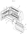
- Figure 2 is a perspective view showing the construction of a bread maker and a mixing bag according to an embodiment of the present invention.
- Figure 3 is a sectional view showing the structure of the bread maker of Figure 2.
- the bread maker includes a housing 20 and a door 30.
- An oven chamber 21 within the housing 20 is used for containing and baking bread.
- the door 30 selectively opens and closes the front of the housing 20.
- the inside surface of the door 30 and the inside surface of the oven chamber 21 have a plurality of heaters 22a, 22b, 22c to heat the inner part of the oven chamber 21 to bake bread with appropriately supplied heat.
- a control knob 23 is formed on the front of the housing 20 to control the operations of the bread maker.
- a display 24 is also formed on the front of the housing 20 to visually provide information to a user.
- An upper roller 41 and a lower roller 42 are mounted on an upper and a lower portion of the oven chamber 21 inside the housing 20.
- the upper and lower ends of a mixing bag 100 are inserted into and held by the upper and lower rollers 41 and 42, respectively.
- the upper roller 41 and the lower roller 42 are extended horizontally and parallel to each other.
- the upper roller 41 and the lower roller 42 can be rotated in both forward and reverse directions by the action of a belt (not shown) that is rotated by a motor (not shown).
- a plurality of fixing projections 41a, 42a are formed on the upper roller 41 and the lower roller 42 and inserted into fixing holes 101, 102 formed in the upper and lower parts of the mixing bag 100, respectively.
- a bar code scanner 43 reads a bar code 103 attached to the mixing bag 100, and is positioned in the upper portion of the interior of the housing 20 close to the upper roller 41 to provide ingredients and cooking information.
- the mixing bag 100 is made of an elastic material, such as vinyl. Dry bread ingredients 110 are contained in the mixing bag 100.
- the dry bread ingredients 110 include grain powder, such as wheat flour, that is the principal ingredient of bread.
- An inner bag 120 containing baking liquid ruptures in the mixing bag 100 so that the baking liquid can be mixed with the dry bread ingredients 110 to form a dough.
- a baking tray 50 forms a bread making space to accommodate the mixing bag 100 in the lower portion of the oven chamber 21 within the housing 20, and detachably mounts to the oven chamber 21.
- the baking tray 50 is, for example, a rectangularly shaped container with a horizontal length and open top.
- a projected fitting part 54 is formed on each lower end of the baking tray 50 and fits within a guiding rail 53 formed on each lower inner surface of the oven chamber 21.
- the baking tray 50 has a detachable front half 51 and a rear half 52.
- a scraper 61 in which a slit 62 is formed to allow the mixing bag 100 to pass therethrough is formed on an upper part of the oven chamber 21.
- the mixing bag 100 is upwardly moved by the rotation of the upper and lower rollers 41 and 42, the mixing bag 100 passes through the slit 62, but the bread ingredients are scraped downward.
- a slit 63 having the same function as that of the slit 62 is formed in the lower part of the baking tray 50.
- the slit 63 of the baking tray 50 through which the mixing bag 100 passes is formed as a gap between the lower surface of the front half 51 and the rear half 52 of the baking tray 50.
- the mixing bag 100 is raised and lowered by the rotation of the upper roller 41 and lower roller 42, but the bread ingredients stay in the baking tray 50 and are mixed to form the dough.
- a sensor 70 senses whether the user has correctly set a front half 51 of the baking tray 50 in the oven chamber 21 after mounting the mixing bag 100.
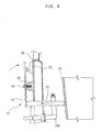
- Figure 4 is a sectional view schematically showing the construction of the baking tray sensor 70 of the bread maker.
- Figure 5 is a perspective view showing the construction of the baking tray sensor 70 shown in Figure 4.
- the sensor 70 has a sensing member 71 that extends through an inner panel 32 of the door 30 and moves back and forth depending on whether the front half 51 of the baking tray 50 is mounted.
- An operating lever 72 makes a seesaw movement depending on the back and forth movement of the sensing member 71, and is set in the space between an outer panel 31 and the inner panel 32 of the door 30.
- a sensing switch 73 is pressed or released according to the movement of the operating lever 72.
- the sensing member 71 is a bar-shaped device, for example, with a predetermined length, and extends from the space between the outer panel 31 and the inner panel 32 of the door 30, through the inner panel 32, to the inner part of the oven chamber 21.
- the sensing member 71 is fixed to one end of the operating lever 72, which is mounted in the space between the outer panel 31 and inner panel 32 of the door 30, and the other end contacts the front half 51 of the baking tray 50 when mounted in the oven chamber 21.
- the sensing member 71 moves back and forth a predetermined distance depending on whether the front half 51 of the baking tray 50 is mounted.
- the operating lever 72 is a flat plate, for example, made of an elastic material with a predetermined length.
- the center of the operating lever 72 is jointed to a projected supporting part 33 from the inner panel 32 of the door 30 by a fixing screw 34.
- the fixing screw 34 is jointed loosely to the operating lever 72 and the supporting part 33 so that the operating lever 72 can make a seesaw movement toward the sensing switch 73 as the sensing member 71 contacts the front half 51 of the baking tray 50 when the front half 51 is mounted and the door 30 is closed.
- the sensing switch 73 is fixed to the inner panel 32 of the door 30 and is pressed by the end of the operating lever 72 that is opposite the sensing member 71 as the operating lever 72 makes seesaw movements.
- the senor 70 is mounted on the door 30, but the sensor 70 may be attached to the bread maker in other ways, such as by mounting the sensing member 71 on a side surface of the oven chamber 21 of the housing 20 such that the sensing member 71 contacts the side surface of the front half 51 of the baking tray 50, with the operating lever 72 and the sensing switch 73 placed in the side part of the housing 20.
- the mixing bag 100 which contains the dry bread ingredients 110, is placed in the housing 20 and a rear half 52 of the baking tray 50 is mounted in the oven chamber 21 before operation of the bread maker.
- the upper and lower ends of the mixing bag 100 are inserted onto and held by the fixing projections 41a and 42a of the upper roller 41 and the lower roller 42, respectively. Then, after mounting the front half 51 of the baking tray 50 in the oven chamber 21, the door 30 is closed.
- the sensing member 71 mounted in the door 30 contacts the front half 51 of the baking tray 50 and moves back toward the door 30 a predetermined distance as the door 30 is closed.
- the sensing member 71 pushes back the bottom part of the operating lever 72, which causes the upper part of the operating lever 72 to press the sensing switch 73.
- the bread maker is able to determine whether the front half 51 of the baking tray 50 has been placed in the oven chamber 21 and mounted correctly.
- the upper roller 41 and the lower roller 42 rotate in both forward and reverse directions to move the mixing bag 100 up and down repeatedly for a predetermined time.
- the mixing bag 100 moves in an upward direction, the mixing bag 100 passes through the slit 62, but the bread ingredients are scraped downward and do not move toward the upper roller 41.
- the mixing bag 100 moves in a downward direction, the mixing bag 100 passes through the slit 63, but the bread ingredients remain in the baking tray 50 to form the dough.
- the inner bag 120 containing the baking liquid ruptures in the mixing bag 100 so that the baking liquid can be mixed with the dry bread ingredients 110 to form the dough.
- the mixing bag 100 moves downward and ruptures. The dough remains in the baking tray 50 while the mixing bag 100 rolls onto the lower roller 42 for disposal.
- the heaters 22a, 22b, 22c which are mounted on the inner surface of the door 30 and the inner part of the oven chamber 21, turn on and heat the inner part of the oven chamber 21 to bake the dough. After baking the bread, the user can open the door 30 and remove the baking tray 50 that holds the baked bread.
- the user may mistakenly not mount the front half 51 of the baking tray 50 and close the door 30 after mounting the mixing bag 100 in the oven chamber 21.
- the sensing member 71 and the operating lever 72 which are mounted in the door 30, do not move. Consequently, the sensing switch 73 is not pressed.
- a control part of the bread maker (not shown) detects that the baking tray 50 is not mounted correctly using the output of the sensing switch 73, and prevents the bread maker from operating.
- embodiments of the present invention provide a bread maker with a sensor that senses whether a baking tray has been mounted. If the baking tray has not been mounted, the bread maker will not operate. Thus, the mixing bag will not rupture when the baking tray has not been installed correctly, avoiding the need to clean the ingredients from the oven chamber 21.
Landscapes
- Life Sciences & Earth Sciences (AREA)
- Engineering & Computer Science (AREA)
- Food Science & Technology (AREA)
- Baking, Grill, Roasting (AREA)
Abstract
Description
- The present invention relates generally to bread makers and to sensors for bread makers.
- A bread maker is an apparatus that makes bread using, for example, a mixing bag containing bread ingredients. The bread maker can automatically make a variety of breads depending on the types of the bread ingredients. Figure 1 is a sectional view showing the structure of a conventional bread maker. As shown in Figure 1, the conventional bread maker includes a
housing 1 defining the outer structure of the bread maker. Thehousing 1 contains anoven chamber 2, and adoor 3 is mounted on the front of thehousing 1 that is selectively opened and closed. Other parts used to make bread are mounted inside thehousing 1. - Upper and
lower rollers mixing bag 4 and raise and lower themixing bag 4 to mix the bread ingredients and form a dough. The upper andlower rollers baking tray 7 forms a bread making space to accommodate themixing bag 4 and fits in the lower part of theoven chamber 2. Thebaking tray 7 has afront half 7a and arear half 7b that can separate from each other. - A
slit 9 is formed in the center of ascraper 10 to allow the upper portion of themixing bag 4 to pass therethrough. Accordingly, when themixing bag 4 is moved upwardly by the rotation of the upper andlower rollers mixing bag 4 passes through theslit 9, but the bread ingredients are scraped downward and do not move upward through theslit 9. Anotherslit 11, which has the same function as that of theslit 9, is formed in the center of thebaking tray 7. - Accordingly, when the
mixing bag 4 moves downwardly by the rotation of the upper andlower rollers mixing bag 4 passes through theslit 11, but the bread ingredients remain in thebaking tray 7 to form the dough. After forming the dough, themixing bag 4 moves in the direction of thelower roller 6 and tears, leaving the dough in thebaking tray 7 as the mixing bag leaves thebaking tray 7 through theslit 11. - A plurality of
heaters oven chamber 2, which is inside thehousing 1, and the inner surface of thedoor 3 to bake the dough with appropriately supplied heat. - When making bread using the conventional bread maker of Figure 1, the
rear half 7b of thebaking tray 7 is placed in theoven chamber 2. Themixing bag 4, which contains thedry bread ingredients 110, is positioned by placing upper and the lower portions of themixing bag 4 through theslit 9 of thescraper 10 and theslit 11 of thebaking tray 7. The upper andlower rollers mixing bag 4. After mounting thefront half 7a of thebaking tray 7 in theoven chamber 2 and closing thedoor 3, the bread maker is ready to be operated. - However, with the conventional bread maker, users mistakenly tend to turn on the bread maker without mounting the
front half 7a of thebaking tray 7 when installing themixing bag 4. In this case, the conventional bread maker operates as usual, causing themixing bag 4 to explode. Thus, the ingredients of themixing bag 4 are spread all over theoven chamber 2, resulting in theoven chamber 2 needing to be cleaned. - It is an aim of preferred embodiments of the present invention to provide a bread maker with a sensor that senses whether the baking tray is correctly mounted and prevent operation of the bread maker when the baking tray is incorrectly mounted.
- According to the present invention in a first aspect, there is provided a bread maker including a housing forming an oven chamber; a door mounted to a front of the housing that is selectively opened and closed; a baking tray detachably mounted in the oven chamber; and a sensor sensing whether the baking tray is mounted.
- Suitably, the sensor includes a sensing member attached to at least one of the housing and the door and moving back and forth a predetermined distance depending upon contact with the baking tray, and a sensing switch sensing movement of the sensing member.
- Suitably, the door comprises an inner panel and an outer panel spaced apart from the inner panel a predetermined distance.
- Suitably, the sensor further comprises an operating lever made of an elastic material that makes a seesaw movement in a space between the inner panel and the outer panel.
- Suitably, one end of the sensing member contacts one end of the operating lever, and the other end of the sensing member penetrates the inner panel and extends into the oven chamber toward the baking tray.
- Suitably, the sensing switch is mounted in a space between the inner panel and the outer panel of the door and is contacted by another end of the operating lever.
- According to the present invention in a second aspect, there is provided a sensor for a bread maker having a housing forming an oven chamber, a door attached to the housing with an inner panel and an outer panel, and a baking tray detachably mounted within the oven chamber, the sensor including a sensing member extending from between the outer panel and the inner panel, through the inner panel, to the oven chamber, and having a first end between the outer panel and the inner panel and a second end within the oven chamber; a sensing switch attached to the inner panel; and an operating lever between the inner panel and the outer panel and having a top end and a bottom end connected to the first end of the sensing member, wherein when the baking tray is mounted in the oven chamber and the door is closed, the second end of the sensing member contacts the baking tray and is pushed back in the direction of the door, the first end pushing back the operating lever to cause the top end of the operating lever to tilt toward and contact the sensing switch to sense whether the baking try is mounted in the oven chamber.
- Further features of the present invention are set out in the appended claims.
- The present invention will from the following detailed description, by way of example only, taken in conjunction with the accompanying drawings, of which:
- Figure 1 is a sectional view schematically showing the structure of a conventional bread maker;
- Figure 2 is a perspective view showing the construction of the bread maker and the mixing bag according to an embodiment of the present invention;
- Figure 3 is a sectional view showing the structure of the bread maker of Figure 2;
- Figure 4 is a sectional view schematically showing the construction of a baking tray sensor of the bread maker of Figure 3; and
- Figure 5 is a perspective view showing the construction of the baking tray sensor of Figure 4 according to the embodiment of the present invention.
- Hereinafter, an embodiment of the present invention will be described in detail with reference to the attached drawings, wherein the like reference numerals refer to the like elements throughout. The present invention may, however, be embodied in many different forms and should not be construed as being limited to the embodiment set forth herein; rather, this embodiment is provided so that the present disclosure will be thorough and complete, and will fully convey the concept of the invention to those skilled in the art.
- Figure 2 is a perspective view showing the construction of a bread maker and a mixing bag according to an embodiment of the present invention. Figure 3 is a sectional view showing the structure of the bread maker of Figure 2. Referring to Figures 2 and 3, the bread maker includes a
housing 20 and adoor 30. Anoven chamber 21 within thehousing 20 is used for containing and baking bread. Thedoor 30 selectively opens and closes the front of thehousing 20. - The inside surface of the
door 30 and the inside surface of theoven chamber 21 have a plurality ofheaters oven chamber 21 to bake bread with appropriately supplied heat. Acontrol knob 23 is formed on the front of thehousing 20 to control the operations of the bread maker. Adisplay 24 is also formed on the front of thehousing 20 to visually provide information to a user. - An
upper roller 41 and alower roller 42 are mounted on an upper and a lower portion of theoven chamber 21 inside thehousing 20. The upper and lower ends of amixing bag 100 are inserted into and held by the upper andlower rollers upper roller 41 and thelower roller 42 are extended horizontally and parallel to each other. Theupper roller 41 and thelower roller 42 can be rotated in both forward and reverse directions by the action of a belt (not shown) that is rotated by a motor (not shown). - A plurality of
fixing projections upper roller 41 and thelower roller 42 and inserted intofixing holes mixing bag 100, respectively. Abar code scanner 43 reads abar code 103 attached to themixing bag 100, and is positioned in the upper portion of the interior of thehousing 20 close to theupper roller 41 to provide ingredients and cooking information. - The
mixing bag 100 is made of an elastic material, such as vinyl.Dry bread ingredients 110 are contained in themixing bag 100. Thedry bread ingredients 110 include grain powder, such as wheat flour, that is the principal ingredient of bread. Aninner bag 120 containing baking liquid ruptures in themixing bag 100 so that the baking liquid can be mixed with thedry bread ingredients 110 to form a dough. - A
baking tray 50 forms a bread making space to accommodate themixing bag 100 in the lower portion of theoven chamber 21 within thehousing 20, and detachably mounts to theoven chamber 21. Thebaking tray 50 is, for example, a rectangularly shaped container with a horizontal length and open top. A projectedfitting part 54 is formed on each lower end of thebaking tray 50 and fits within a guidingrail 53 formed on each lower inner surface of theoven chamber 21. Thebaking tray 50 has a detachablefront half 51 and arear half 52. - A
scraper 61 in which aslit 62 is formed to allow themixing bag 100 to pass therethrough is formed on an upper part of theoven chamber 21. When themixing bag 100 is upwardly moved by the rotation of the upper andlower rollers mixing bag 100 passes through theslit 62, but the bread ingredients are scraped downward. A slit 63 having the same function as that of theslit 62 is formed in the lower part of thebaking tray 50. Theslit 63 of thebaking tray 50 through which the mixingbag 100 passes is formed as a gap between the lower surface of thefront half 51 and therear half 52 of thebaking tray 50. - Thus, the mixing
bag 100 is raised and lowered by the rotation of theupper roller 41 andlower roller 42, but the bread ingredients stay in thebaking tray 50 and are mixed to form the dough. - According to the embodiment of the present invention, a
sensor 70 senses whether the user has correctly set afront half 51 of thebaking tray 50 in theoven chamber 21 after mounting the mixingbag 100. - Figure 4 is a sectional view schematically showing the construction of the
baking tray sensor 70 of the bread maker. Figure 5 is a perspective view showing the construction of thebaking tray sensor 70 shown in Figure 4. - As shown in Figure 3 through Figure 5, the
sensor 70 has a sensingmember 71 that extends through aninner panel 32 of thedoor 30 and moves back and forth depending on whether thefront half 51 of thebaking tray 50 is mounted. An operatinglever 72 makes a seesaw movement depending on the back and forth movement of the sensingmember 71, and is set in the space between anouter panel 31 and theinner panel 32 of thedoor 30. Asensing switch 73 is pressed or released according to the movement of the operatinglever 72. - The sensing
member 71 is a bar-shaped device, for example, with a predetermined length, and extends from the space between theouter panel 31 and theinner panel 32 of thedoor 30, through theinner panel 32, to the inner part of theoven chamber 21. The sensingmember 71 is fixed to one end of the operatinglever 72, which is mounted in the space between theouter panel 31 andinner panel 32 of thedoor 30, and the other end contacts thefront half 51 of thebaking tray 50 when mounted in theoven chamber 21. The sensingmember 71 moves back and forth a predetermined distance depending on whether thefront half 51 of thebaking tray 50 is mounted. - The operating
lever 72 is a flat plate, for example, made of an elastic material with a predetermined length. The center of the operatinglever 72 is jointed to a projected supportingpart 33 from theinner panel 32 of thedoor 30 by a fixingscrew 34. The fixingscrew 34 is jointed loosely to the operatinglever 72 and the supportingpart 33 so that the operatinglever 72 can make a seesaw movement toward thesensing switch 73 as the sensingmember 71 contacts thefront half 51 of thebaking tray 50 when thefront half 51 is mounted and thedoor 30 is closed. Thesensing switch 73 is fixed to theinner panel 32 of thedoor 30 and is pressed by the end of the operatinglever 72 that is opposite the sensingmember 71 as the operatinglever 72 makes seesaw movements. - In the embodiment of the present invention shown in Figure 3, the
sensor 70 is mounted on thedoor 30, but thesensor 70 may be attached to the bread maker in other ways, such as by mounting the sensingmember 71 on a side surface of theoven chamber 21 of thehousing 20 such that the sensingmember 71 contacts the side surface of thefront half 51 of thebaking tray 50, with the operatinglever 72 and thesensing switch 73 placed in the side part of thehousing 20. - The application and operation of the bread maker according to an embodiment of the present invention is described below with reference to Figures 3 through 5.
- To make bread, the mixing
bag 100, which contains thedry bread ingredients 110, is placed in thehousing 20 and arear half 52 of thebaking tray 50 is mounted in theoven chamber 21 before operation of the bread maker. The upper and lower ends of the mixingbag 100 are inserted onto and held by the fixingprojections upper roller 41 and thelower roller 42, respectively. Then, after mounting thefront half 51 of thebaking tray 50 in theoven chamber 21, thedoor 30 is closed. - When the
front half 51 of thebaking tray 50 has been mounted in theoven chamber 21, the sensingmember 71 mounted in thedoor 30 contacts thefront half 51 of thebaking tray 50 and moves back toward the door 30 a predetermined distance as thedoor 30 is closed. The sensingmember 71 pushes back the bottom part of the operatinglever 72, which causes the upper part of the operatinglever 72 to press thesensing switch 73. Thus, the bread maker is able to determine whether thefront half 51 of thebaking tray 50 has been placed in theoven chamber 21 and mounted correctly. - The
upper roller 41 and thelower roller 42 rotate in both forward and reverse directions to move the mixingbag 100 up and down repeatedly for a predetermined time. When the mixingbag 100 moves in an upward direction, the mixingbag 100 passes through theslit 62, but the bread ingredients are scraped downward and do not move toward theupper roller 41. When the mixingbag 100 moves in a downward direction, the mixingbag 100 passes through theslit 63, but the bread ingredients remain in thebaking tray 50 to form the dough. Theinner bag 120 containing the baking liquid ruptures in the mixingbag 100 so that the baking liquid can be mixed with thedry bread ingredients 110 to form the dough. - After the dough has been formed, the mixing
bag 100 moves downward and ruptures. The dough remains in thebaking tray 50 while the mixingbag 100 rolls onto thelower roller 42 for disposal. - When mixing is completed, the
heaters door 30 and the inner part of theoven chamber 21, turn on and heat the inner part of theoven chamber 21 to bake the dough. After baking the bread, the user can open thedoor 30 and remove thebaking tray 50 that holds the baked bread. - However, the user may mistakenly not mount the
front half 51 of thebaking tray 50 and close thedoor 30 after mounting the mixingbag 100 in theoven chamber 21. In this case, when thedoor 30 is closed, the sensingmember 71 and the operatinglever 72, which are mounted in thedoor 30, do not move. Consequently, thesensing switch 73 is not pressed. A control part of the bread maker (not shown) detects that thebaking tray 50 is not mounted correctly using the output of thesensing switch 73, and prevents the bread maker from operating. - As described above, embodiments of the present invention provide a bread maker with a sensor that senses whether a baking tray has been mounted. If the baking tray has not been mounted, the bread maker will not operate. Thus, the mixing bag will not rupture when the baking tray has not been installed correctly, avoiding the need to clean the ingredients from the
oven chamber 21. - Although an embodiment of the present invention has been shown and described, it will be appreciated by those skilled in the art that various modifications, additions, and substitutions are possible, without departing from the principles and spirit of the invention, the scope of which is defined in the accompanying claims and their equivalents.
- Attention is directed to all papers and documents which are filed concurrently with or previous to this specification in connection with this application and which are open to public inspection with this specification, and the contents of all such papers and documents are incorporated herein by reference.
- All of the features disclosed in this specification (including any accompanying claims, abstract and drawings), and/or all of the steps of any method or process so disclosed, may be combined in any combination, except combinations where at least some of such features and/or steps are mutually exclusive.
- Each feature disclosed in this specification (including any accompanying claims, abstract and drawings) may be replaced by alternative features serving the same, equivalent or similar purpose, unless expressly stated otherwise. Thus, unless expressly stated otherwise, each feature disclosed is one example only of a generic series of equivalent or similar features.
- The invention is not restricted to the details of the foregoing embodiment(s). The invention extends to any novel one, or any novel combination, of the features disclosed in this specification (including any accompanying claims, abstract and drawings), or to any novel one, or any novel combination, of the steps of any method or process so disclosed.
Claims (15)
- bread maker, comprising:a housing (20) forming an oven chamber (21);a door (30) mounted to a front of the housing (20) that is selectively opened and closed;a baking tray (50) detachably mounted in the oven chamber (21); anda sensor (70) sensing whether the baking tray (50) is mounted.
- The bread maker according to claim 1, wherein the sensor (70) comprises:a sensing member (71) attached to at least one of the housing (20) and the door (30) and moving back and forth a predetermined distance depending upon contact with the baking tray (50); anda sensing switch (73) sensing movement of the sensing member (71).
- The bread maker according to claim 2, wherein the door (30) comprises an inner panel (32) and an outer panel (31) spaced apart from the inner panel (32).
- The bread maker according to claim 3, wherein the sensor (70) further comprises an operating lever (72) made of an elastic material that makes a seesaw movement in a space between the inner panel (32) and the outer panel (31), wherein
one end of the sensing member (71) contacts one end of the operating lever (72), and the other end of the sensing member (71) penetrates the inner panel (32) and extends into the oven chamber (21) toward the baking tray (50), and
the sensing switch (73) is mounted in a space between the inner panel (32) and the outer panel (31) of the door (30) and is contacted by another end of the operating lever (72). - The bread maker according to any preceding claim, further comprising:an upper roller (41) and a lower roller (42) mounted on an upper and a lower portion of the oven chamber (21), the upper roller (41) and the lower roller (42) having a plurality of projections (41a, 42a); anda mixing bag (100) having a plurality of holes (101) on an upper end and a lower end thereof to receive the projections (41a, 42a) of the upper roller (41) and the lower roller (42), respectively.
- The bread maker according to claim 5, further comprising a bar code scanner (43) positioned in an upper portion of the housing (20) close to the upper roller (41), the bar code scanner (43) reading a bar code (103) attached to the mixing bag (100) to provide ingredients and cooking information.
- The bread maker according to claim 5 or claim 6, wherein the mixing bag (100) contains dry bread ingredients and an inner bag (120) with a baking liquid, the upper roller (41) and the lower roller (42) rotating to move the mixing bag (100) up and down, and the inner bag (120) being torn as the mixing bag (100) moves up and down to mix the baking liquid with the dry bread ingredients and form a dough.
- The bread maker according to any one of claims 5-7, wherein the baking tray (50) comprises a front half (51) and a rear half (52), separate from the front half, with a slit (63) between the front half (51) and the rear half (52), the front half (51) being detachably mounted in the oven chamber (21).
- The bread maker according to claim 8, further comprising a scraper (61), having a slit (62), in the upper portion of the oven chamber (21), the mixing bag (100) being placed between the slit (62) of the scraper and the slit (63) of the baking tray (50) when attached to the upper roller (41) and the lower roller (42), the bread ingredients being scraped downward by the scraper (61) as the mixing bag moves upward through the slit (62) of the scraper (61), and the bread ingredients being scraped upward as the mixing bag (100) moves downward through slit (63) in the baking tray (50) to remain in the baking tray (50) .
- The bread maker according to claim 8 or claim 9, wherein after the dough has been formed, the mixing bag (100) moves downward by rotation of the upper roller (41) and the lower roller (42) and ruptures, the dough remaining in the baking tray (50) as the mixing bag (100) passes through the slit (63) of the baking tray (50) and rolls onto the lower roller (42) for disposal.
- The bread maker according to any preceding claim, wherein the sensor (70) is mounted on a side surface of the oven chamber (21).
- A sensor (70) for a bread maker having a housing (20) forming an oven chamber (21), a door (30) attached to the housing with an inner panel (32) and an outer panel (31), and a baking tray (50) detachably mounted within the oven chamber (21), the sensor (70) comprising:a sensing member (71) extending from between the outer panel (31) and the inner panel (32), through the inner panel (32), to the oven chamber (21), and having a first end between the outer panel (31) and the inner panel (32) and a second end within the oven chamber (21);a sensing switch (73) attached to the inner panel (32); andan operating lever (72) between the inner panel (32) and the outer panel (31) and having a top end and a bottom end connected to the first end of the sensing member (71),wherein when the baking tray (50) is mounted in the oven chamber (21) and the door (30) is closed, the second end of the sensing member (71) contacts the baking tray (50) and is pushed back in the direction of the door (30), the first end pushing back the operating lever (72) to cause the top end of the operating lever (72) to tilt toward and contact the sensing switch (73) to sense whether the baking tray (50) is mounted in the oven chamber (21).
- The sensor (70) according to claim 12, further comprising a projected supporting part (33) connected to the inner panel (32) between the sensing switch (73) and the sensing member (71) and projecting toward the operating lever (72), a center of the operating lever (72) being loosely attached to the projected supporting part (33), the operating lever (72) pivoting on the projected supporting part (33) to press the top of the operating lever (72) against the sensing switch (73) as the first end of the sensing member (70) pushes back the bottom end of the operating lever (72) as the door (30) is closed.
- The sensor (70) according to claim 12 or claim 13, wherein the operating lever (72) is made of an elastic material.
- The sensor (70) according to any one of claims 12-14, wherein the sensor (70) is mounted on a side surface of the oven chamber (21).
Applications Claiming Priority (2)
| Application Number | Priority Date | Filing Date | Title |
|---|---|---|---|
| KR2002055993 | 2002-09-14 | ||
| KR10-2002-0055993A KR100473061B1 (en) | 2002-09-14 | 2002-09-14 | Baking Apparatus |
Publications (2)
| Publication Number | Publication Date |
|---|---|
| EP1402804A1 true EP1402804A1 (en) | 2004-03-31 |
| EP1402804B1 EP1402804B1 (en) | 2005-05-11 |
Family
ID=36202216
Family Applications (1)
| Application Number | Title | Priority Date | Filing Date |
|---|---|---|---|
| EP03251235A Expired - Lifetime EP1402804B1 (en) | 2002-09-14 | 2003-02-28 | Bread maker & sensor for bread maker |
Country Status (6)
| Country | Link |
|---|---|
| US (1) | US6729227B2 (en) |
| EP (1) | EP1402804B1 (en) |
| JP (1) | JP3741693B2 (en) |
| KR (1) | KR100473061B1 (en) |
| CN (1) | CN1248587C (en) |
| DE (1) | DE60300638T2 (en) |
Cited By (1)
| Publication number | Priority date | Publication date | Assignee | Title |
|---|---|---|---|---|
| EP1475021A1 (en) * | 2003-05-07 | 2004-11-10 | Samsung Electronics Co., Ltd. | Bread maker |
Families Citing this family (7)
| Publication number | Priority date | Publication date | Assignee | Title |
|---|---|---|---|---|
| KR20040096135A (en) * | 2003-05-07 | 2004-11-16 | 삼성전자주식회사 | Bake oven |
| KR20040096217A (en) * | 2003-05-07 | 2004-11-16 | 삼성전자주식회사 | Oven for baking bread |
| KR20040096137A (en) * | 2003-05-07 | 2004-11-16 | 삼성전자주식회사 | Baking machine and control method thereof |
| KR20040096218A (en) * | 2003-05-07 | 2004-11-16 | 삼성전자주식회사 | Bake oven |
| KR20040096215A (en) * | 2003-05-07 | 2004-11-16 | 삼성전자주식회사 | Oven for Baking Bread |
| CN102144897B (en) * | 2010-02-05 | 2014-05-28 | 漳州灿坤实业有限公司 | Bread self-making method, bread machine and bread dosing box |
| CN103654457B (en) * | 2012-09-19 | 2017-06-20 | 漳州灿坤实业有限公司 | A quick bread making machine, bread raw material box and bread making method |
Citations (6)
| Publication number | Priority date | Publication date | Assignee | Title |
|---|---|---|---|---|
| US4803086A (en) * | 1985-12-23 | 1989-02-07 | Heden-Team Aktiengesellschaft | Automatically making food products such as bread, cakes and the like |
| GB2213698A (en) * | 1987-06-05 | 1989-08-23 | Matsushita Electric Industrial Co Ltd | Bread making machine |
| JPH02126026A (en) * | 1988-11-01 | 1990-05-15 | Toshiba Corp | Heating and cooking device with home bakery function |
| WO1999025467A1 (en) * | 1997-11-17 | 1999-05-27 | Heden-Team Ag | Automatic baking apparatus and mixbag therefor |
| US6029563A (en) * | 1998-09-18 | 2000-02-29 | Sanyo Electric Co., Ltd. | Cooking machine |
| US6053096A (en) * | 1995-01-06 | 2000-04-25 | Matsushita Electric Industrial Co., Ltd. | Automatic bread producing machine |
Family Cites Families (8)
| Publication number | Priority date | Publication date | Assignee | Title |
|---|---|---|---|---|
| SE8207438D0 (en) * | 1982-12-28 | 1982-12-28 | Gunnar Hedenberg | KIT FOR MANUFACTURE OF FOOD PRODUCTS LIKE BREAD, COOKIES AND SIMILAR AND BAKING MACHINE FOR MANUFACTURE OF SAID PRODUCTS |
| US4550654A (en) * | 1983-04-01 | 1985-11-05 | Heden Team A.G. | Apparatus for automatic preparation of food products such as bread, cakes and the like |
| US4590850A (en) * | 1983-12-27 | 1986-05-27 | Heden Team A.G. | Apparatus for automatically making of food products such as bread, cakes and the like |
| US5146840A (en) | 1989-11-22 | 1992-09-15 | Heden-Team Ag | Automatic baking apparatus and mixbag therefore |
| KR960036241U (en) * | 1995-05-15 | 1996-12-16 | Baking container presence detection device of household bakery | |
| US6321641B1 (en) * | 1999-07-02 | 2001-11-27 | Donglei Wang | Multi-chamber bread-baking machine |
| KR100421858B1 (en) * | 2000-12-08 | 2004-03-09 | 엘지전자 주식회사 | Microwave oven combined with toaster and method for controling the same |
| KR100416003B1 (en) * | 2002-02-28 | 2004-01-24 | 삼성전자주식회사 | Baking machine |
-
2002
- 2002-09-14 KR KR10-2002-0055993A patent/KR100473061B1/en not_active Expired - Fee Related
-
2003
- 2003-02-28 EP EP03251235A patent/EP1402804B1/en not_active Expired - Lifetime
- 2003-02-28 DE DE60300638T patent/DE60300638T2/en not_active Expired - Fee Related
- 2003-03-06 CN CNB031068820A patent/CN1248587C/en not_active Expired - Fee Related
- 2003-03-12 US US10/385,746 patent/US6729227B2/en not_active Expired - Fee Related
- 2003-04-07 JP JP2003103326A patent/JP3741693B2/en not_active Expired - Fee Related
Patent Citations (6)
| Publication number | Priority date | Publication date | Assignee | Title |
|---|---|---|---|---|
| US4803086A (en) * | 1985-12-23 | 1989-02-07 | Heden-Team Aktiengesellschaft | Automatically making food products such as bread, cakes and the like |
| GB2213698A (en) * | 1987-06-05 | 1989-08-23 | Matsushita Electric Industrial Co Ltd | Bread making machine |
| JPH02126026A (en) * | 1988-11-01 | 1990-05-15 | Toshiba Corp | Heating and cooking device with home bakery function |
| US6053096A (en) * | 1995-01-06 | 2000-04-25 | Matsushita Electric Industrial Co., Ltd. | Automatic bread producing machine |
| WO1999025467A1 (en) * | 1997-11-17 | 1999-05-27 | Heden-Team Ag | Automatic baking apparatus and mixbag therefor |
| US6029563A (en) * | 1998-09-18 | 2000-02-29 | Sanyo Electric Co., Ltd. | Cooking machine |
Non-Patent Citations (1)
| Title |
|---|
| PATENT ABSTRACTS OF JAPAN vol. 014, no. 357 (M - 1005) 2 August 1990 (1990-08-02) * |
Cited By (2)
| Publication number | Priority date | Publication date | Assignee | Title |
|---|---|---|---|---|
| EP1475021A1 (en) * | 2003-05-07 | 2004-11-10 | Samsung Electronics Co., Ltd. | Bread maker |
| US7296509B2 (en) | 2003-05-07 | 2007-11-20 | Samsung Electronics Co., Ltd. | Bread maker |
Also Published As
| Publication number | Publication date |
|---|---|
| DE60300638D1 (en) | 2005-06-16 |
| EP1402804B1 (en) | 2005-05-11 |
| DE60300638T2 (en) | 2006-05-04 |
| JP3741693B2 (en) | 2006-02-01 |
| CN1481691A (en) | 2004-03-17 |
| US20040050257A1 (en) | 2004-03-18 |
| JP2004105702A (en) | 2004-04-08 |
| KR100473061B1 (en) | 2005-03-10 |
| KR20040024396A (en) | 2004-03-20 |
| CN1248587C (en) | 2006-04-05 |
| US6729227B2 (en) | 2004-05-04 |
Similar Documents
| Publication | Publication Date | Title |
|---|---|---|
| CA1104878A (en) | Method of making bread and apparatus therefor | |
| JP3191645B2 (en) | Automatic bread maker | |
| EP1402804A1 (en) | Bread maker & sensor for bread maker | |
| US6774345B1 (en) | Method and device for preparing foodstuffs by baking inside an oven cavity | |
| GB2280829A (en) | Microwave oven having non-contact temperature sensor for food | |
| EP1382254A1 (en) | Improvements in and relating to bread makers | |
| JP2009060932A (en) | Automatic bread maker | |
| EP1382258A1 (en) | Bread maker and control method thereof | |
| EP1382253B1 (en) | Improvements in and relating to bread makers | |
| JP2010035910A (en) | Automatic bread maker | |
| JP2014050625A (en) | Automatic bread machine | |
| JP2010094418A (en) | Automatic bread making machine | |
| EP1474979B1 (en) | Bread maker | |
| KR200227114Y1 (en) | Automatic Squid Electric Grill | |
| JPH02251480A (en) | Discarded plate processing equipment | |
| KR0121913Y1 (en) | Fully automatic toaster | |
| CN213046583U (en) | Cake making machine with safety door | |
| JP4668856B2 (en) | Bread machine | |
| EP1474985A1 (en) | Bread maker | |
| US20230057981A1 (en) | Smart hot plates | |
| EP1475021A1 (en) | Bread maker | |
| GB2411342A (en) | Automatic contact grill | |
| JP2009261694A (en) | Automatic bread maker | |
| JPS63305825A (en) | Bread maker | |
| JPH01181822A (en) | automatic bread machine |
Legal Events
| Date | Code | Title | Description |
|---|---|---|---|
| PUAI | Public reference made under article 153(3) epc to a published international application that has entered the european phase |
Free format text: ORIGINAL CODE: 0009012 |
|
| 17P | Request for examination filed |
Effective date: 20030310 |
|
| AK | Designated contracting states |
Kind code of ref document: A1 Designated state(s): AT BE BG CH CY CZ DE DK EE ES FI FR GB GR HU IE IT LI LU MC NL PT SE SI SK TR |
|
| AX | Request for extension of the european patent |
Extension state: AL LT LV MK RO |
|
| 17Q | First examination report despatched |
Effective date: 20040507 |
|
| GRAP | Despatch of communication of intention to grant a patent |
Free format text: ORIGINAL CODE: EPIDOSNIGR1 |
|
| AKX | Designation fees paid |
Designated state(s): DE FR GB SE |
|
| GRAS | Grant fee paid |
Free format text: ORIGINAL CODE: EPIDOSNIGR3 |
|
| GRAA | (expected) grant |
Free format text: ORIGINAL CODE: 0009210 |
|
| AK | Designated contracting states |
Kind code of ref document: B1 Designated state(s): DE FR GB SE |
|
| REG | Reference to a national code |
Ref country code: GB Ref legal event code: FG4D |
|
| REG | Reference to a national code |
Ref country code: IE Ref legal event code: FG4D |
|
| REF | Corresponds to: |
Ref document number: 60300638 Country of ref document: DE Date of ref document: 20050616 Kind code of ref document: P |
|
| REG | Reference to a national code |
Ref country code: SE Ref legal event code: TRGR |
|
| PLBE | No opposition filed within time limit |
Free format text: ORIGINAL CODE: 0009261 |
|
| STAA | Information on the status of an ep patent application or granted ep patent |
Free format text: STATUS: NO OPPOSITION FILED WITHIN TIME LIMIT |
|
| ET | Fr: translation filed | ||
| 26N | No opposition filed |
Effective date: 20060214 |
|
| PGFP | Annual fee paid to national office [announced via postgrant information from national office to epo] |
Ref country code: DE Payment date: 20090123 Year of fee payment: 7 |
|
| PGFP | Annual fee paid to national office [announced via postgrant information from national office to epo] |
Ref country code: GB Payment date: 20090225 Year of fee payment: 7 |
|
| PGFP | Annual fee paid to national office [announced via postgrant information from national office to epo] |
Ref country code: SE Payment date: 20090206 Year of fee payment: 7 |
|
| PGFP | Annual fee paid to national office [announced via postgrant information from national office to epo] |
Ref country code: FR Payment date: 20090213 Year of fee payment: 7 |
|
| GBPC | Gb: european patent ceased through non-payment of renewal fee |
Effective date: 20100228 |
|
| EUG | Se: european patent has lapsed | ||
| REG | Reference to a national code |
Ref country code: FR Ref legal event code: ST Effective date: 20101029 |
|
| PG25 | Lapsed in a contracting state [announced via postgrant information from national office to epo] |
Ref country code: FR Free format text: LAPSE BECAUSE OF NON-PAYMENT OF DUE FEES Effective date: 20100301 |
|
| PG25 | Lapsed in a contracting state [announced via postgrant information from national office to epo] |
Ref country code: DE Free format text: LAPSE BECAUSE OF NON-PAYMENT OF DUE FEES Effective date: 20100901 |
|
| PG25 | Lapsed in a contracting state [announced via postgrant information from national office to epo] |
Ref country code: GB Free format text: LAPSE BECAUSE OF NON-PAYMENT OF DUE FEES Effective date: 20100228 |
|
| PG25 | Lapsed in a contracting state [announced via postgrant information from national office to epo] |
Ref country code: SE Free format text: LAPSE BECAUSE OF NON-PAYMENT OF DUE FEES Effective date: 20100301 |