EP1401356B1 - Apparatus and kit for use during ventricular restoration - Google Patents
Apparatus and kit for use during ventricular restoration Download PDFInfo
- Publication number
- EP1401356B1 EP1401356B1 EP02729297A EP02729297A EP1401356B1 EP 1401356 B1 EP1401356 B1 EP 1401356B1 EP 02729297 A EP02729297 A EP 02729297A EP 02729297 A EP02729297 A EP 02729297A EP 1401356 B1 EP1401356 B1 EP 1401356B1
- Authority
- EP
- European Patent Office
- Prior art keywords
- balloon
- left ventricle
- patch
- shape
- size
- Prior art date
- Legal status (The legal status is an assumption and is not a legal conclusion. Google has not performed a legal analysis and makes no representation as to the accuracy of the status listed.)
- Expired - Lifetime
Links
- 230000002861 ventricular Effects 0.000 title abstract description 13
- 210000005240 left ventricle Anatomy 0.000 claims abstract description 100
- 210000002216 heart Anatomy 0.000 claims abstract description 83
- 238000004513 sizing Methods 0.000 claims abstract description 56
- 230000033001 locomotion Effects 0.000 claims abstract description 21
- 239000000560 biocompatible material Substances 0.000 claims abstract description 20
- 238000001356 surgical procedure Methods 0.000 claims abstract description 17
- 239000012530 fluid Substances 0.000 claims description 53
- 239000000463 material Substances 0.000 claims description 44
- 238000005520 cutting process Methods 0.000 claims description 17
- 238000004891 communication Methods 0.000 claims description 12
- 238000002278 reconstructive surgery Methods 0.000 claims description 5
- 235000014443 Pyrus communis Nutrition 0.000 claims description 2
- 238000007493 shaping process Methods 0.000 abstract description 58
- 238000000034 method Methods 0.000 abstract description 32
- 210000001519 tissue Anatomy 0.000 description 30
- 239000008280 blood Substances 0.000 description 29
- 210000004369 blood Anatomy 0.000 description 29
- 210000004165 myocardium Anatomy 0.000 description 13
- 238000005086 pumping Methods 0.000 description 13
- 230000009471 action Effects 0.000 description 11
- 229910052751 metal Inorganic materials 0.000 description 11
- 239000002184 metal Substances 0.000 description 11
- 239000000945 filler Substances 0.000 description 10
- 239000000835 fiber Substances 0.000 description 9
- 230000006870 function Effects 0.000 description 9
- 238000002595 magnetic resonance imaging Methods 0.000 description 9
- TZCXTZWJZNENPQ-UHFFFAOYSA-L barium sulfate Chemical compound [Ba+2].[O-]S([O-])(=O)=O TZCXTZWJZNENPQ-UHFFFAOYSA-L 0.000 description 8
- 239000000499 gel Substances 0.000 description 7
- 229920000642 polymer Polymers 0.000 description 7
- 210000005241 right ventricle Anatomy 0.000 description 7
- 210000003205 muscle Anatomy 0.000 description 6
- 229910001000 nickel titanium Inorganic materials 0.000 description 6
- 230000008569 process Effects 0.000 description 6
- 239000010935 stainless steel Substances 0.000 description 6
- 229910001220 stainless steel Inorganic materials 0.000 description 6
- 230000008859 change Effects 0.000 description 5
- 230000000694 effects Effects 0.000 description 5
- 230000002107 myocardial effect Effects 0.000 description 5
- HLXZNVUGXRDIFK-UHFFFAOYSA-N nickel titanium Chemical compound [Ti].[Ti].[Ti].[Ti].[Ti].[Ti].[Ti].[Ti].[Ti].[Ti].[Ti].[Ni].[Ni].[Ni].[Ni].[Ni].[Ni].[Ni].[Ni].[Ni].[Ni].[Ni].[Ni].[Ni].[Ni] HLXZNVUGXRDIFK-UHFFFAOYSA-N 0.000 description 5
- 229920001296 polysiloxane Polymers 0.000 description 5
- 231100000241 scar Toxicity 0.000 description 5
- 208000006029 Cardiomegaly Diseases 0.000 description 4
- 239000000853 adhesive Substances 0.000 description 4
- 230000001070 adhesive effect Effects 0.000 description 4
- 210000001992 atrioventricular node Anatomy 0.000 description 4
- 239000000975 dye Substances 0.000 description 4
- BASFCYQUMIYNBI-UHFFFAOYSA-N platinum Chemical compound [Pt] BASFCYQUMIYNBI-UHFFFAOYSA-N 0.000 description 4
- 230000033764 rhythmic process Effects 0.000 description 4
- 210000000115 thoracic cavity Anatomy 0.000 description 4
- 206010019280 Heart failures Diseases 0.000 description 3
- 206010048858 Ischaemic cardiomyopathy Diseases 0.000 description 3
- FAPWRFPIFSIZLT-UHFFFAOYSA-M Sodium chloride Chemical compound [Na+].[Cl-] FAPWRFPIFSIZLT-UHFFFAOYSA-M 0.000 description 3
- 230000017488 activation-induced cell death of T cell Effects 0.000 description 3
- 230000008602 contraction Effects 0.000 description 3
- 238000007796 conventional method Methods 0.000 description 3
- 230000010339 dilation Effects 0.000 description 3
- 238000011156 evaluation Methods 0.000 description 3
- 239000004744 fabric Substances 0.000 description 3
- 230000023597 hemostasis Effects 0.000 description 3
- 208000028867 ischemia Diseases 0.000 description 3
- 238000005304 joining Methods 0.000 description 3
- 229920000126 latex Polymers 0.000 description 3
- 210000003516 pericardium Anatomy 0.000 description 3
- 239000004033 plastic Substances 0.000 description 3
- 229920003023 plastic Polymers 0.000 description 3
- 238000002600 positron emission tomography Methods 0.000 description 3
- 230000002980 postoperative effect Effects 0.000 description 3
- 238000003825 pressing Methods 0.000 description 3
- 210000005245 right atrium Anatomy 0.000 description 3
- 241000283690 Bos taurus Species 0.000 description 2
- 206010007559 Cardiac failure congestive Diseases 0.000 description 2
- 102000008186 Collagen Human genes 0.000 description 2
- 108010035532 Collagen Proteins 0.000 description 2
- 206010042434 Sudden death Diseases 0.000 description 2
- 230000001154 acute effect Effects 0.000 description 2
- 210000001765 aortic valve Anatomy 0.000 description 2
- 238000013459 approach Methods 0.000 description 2
- QVGXLLKOCUKJST-UHFFFAOYSA-N atomic oxygen Chemical compound [O] QVGXLLKOCUKJST-UHFFFAOYSA-N 0.000 description 2
- 238000010009 beating Methods 0.000 description 2
- 230000000747 cardiac effect Effects 0.000 description 2
- 239000011248 coating agent Substances 0.000 description 2
- 238000000576 coating method Methods 0.000 description 2
- 229920001436 collagen Polymers 0.000 description 2
- 210000004351 coronary vessel Anatomy 0.000 description 2
- 230000007423 decrease Effects 0.000 description 2
- 238000000151 deposition Methods 0.000 description 2
- 230000008021 deposition Effects 0.000 description 2
- 230000001627 detrimental effect Effects 0.000 description 2
- 238000010291 electrical method Methods 0.000 description 2
- 230000007831 electrophysiology Effects 0.000 description 2
- 238000002001 electrophysiology Methods 0.000 description 2
- 239000003292 glue Substances 0.000 description 2
- 210000002837 heart atrium Anatomy 0.000 description 2
- 238000003384 imaging method Methods 0.000 description 2
- 238000007735 ion beam assisted deposition Methods 0.000 description 2
- 150000002500 ions Chemical class 0.000 description 2
- 230000000302 ischemic effect Effects 0.000 description 2
- 239000004816 latex Substances 0.000 description 2
- 210000004072 lung Anatomy 0.000 description 2
- 238000013507 mapping Methods 0.000 description 2
- 210000004115 mitral valve Anatomy 0.000 description 2
- 208000010125 myocardial infarction Diseases 0.000 description 2
- 210000001087 myotubule Anatomy 0.000 description 2
- 229910052760 oxygen Inorganic materials 0.000 description 2
- 239000001301 oxygen Substances 0.000 description 2
- 229910052697 platinum Inorganic materials 0.000 description 2
- 229920000728 polyester Polymers 0.000 description 2
- -1 polyethylene Polymers 0.000 description 2
- 238000007634 remodeling Methods 0.000 description 2
- 230000008439 repair process Effects 0.000 description 2
- 229920002994 synthetic fiber Polymers 0.000 description 2
- 229920001169 thermoplastic Polymers 0.000 description 2
- 230000008719 thickening Effects 0.000 description 2
- XLYOFNOQVPJJNP-UHFFFAOYSA-N water Chemical compound O XLYOFNOQVPJJNP-UHFFFAOYSA-N 0.000 description 2
- 238000009941 weaving Methods 0.000 description 2
- PKDBCJSWQUOKDO-UHFFFAOYSA-M 2,3,5-triphenyltetrazolium chloride Chemical compound [Cl-].C1=CC=CC=C1C(N=[N+]1C=2C=CC=CC=2)=NN1C1=CC=CC=C1 PKDBCJSWQUOKDO-UHFFFAOYSA-M 0.000 description 1
- ZAUBLHAXDOQERL-UHFFFAOYSA-N Ataline Natural products CC(C)C1Oc2cc(O)c3C(=O)c4cccc(Oc5ccc6C(=O)c7c(O)cc8OC(C)(C)C=Cc8c7N(C)c6c5O)c4N(C)c3c2C1O ZAUBLHAXDOQERL-UHFFFAOYSA-N 0.000 description 1
- 229910001020 Au alloy Inorganic materials 0.000 description 1
- 108010027529 Bio-glue Proteins 0.000 description 1
- 208000031229 Cardiomyopathies Diseases 0.000 description 1
- 206010053567 Coagulopathies Diseases 0.000 description 1
- 208000001778 Coronary Occlusion Diseases 0.000 description 1
- 206010011086 Coronary artery occlusion Diseases 0.000 description 1
- 102000004420 Creatine Kinase Human genes 0.000 description 1
- 108010042126 Creatine kinase Proteins 0.000 description 1
- 229920001651 Cyanoacrylate Polymers 0.000 description 1
- 229920004934 Dacron® Polymers 0.000 description 1
- 108010010803 Gelatin Proteins 0.000 description 1
- 229920000544 Gore-Tex Polymers 0.000 description 1
- 206010061216 Infarction Diseases 0.000 description 1
- 229920002633 Kraton (polymer) Polymers 0.000 description 1
- 241001465754 Metazoa Species 0.000 description 1
- MWCLLHOVUTZFKS-UHFFFAOYSA-N Methyl cyanoacrylate Chemical compound COC(=O)C(=C)C#N MWCLLHOVUTZFKS-UHFFFAOYSA-N 0.000 description 1
- 239000004677 Nylon Substances 0.000 description 1
- 239000004698 Polyethylene Substances 0.000 description 1
- 206010037368 Pulmonary congestion Diseases 0.000 description 1
- RTAQQCXQSZGOHL-UHFFFAOYSA-N Titanium Chemical compound [Ti] RTAQQCXQSZGOHL-UHFFFAOYSA-N 0.000 description 1
- 241001147416 Ursus maritimus Species 0.000 description 1
- 206010047281 Ventricular arrhythmia Diseases 0.000 description 1
- 238000002679 ablation Methods 0.000 description 1
- 239000000956 alloy Substances 0.000 description 1
- 238000004458 analytical method Methods 0.000 description 1
- 238000002399 angioplasty Methods 0.000 description 1
- 229940030225 antihemorrhagics Drugs 0.000 description 1
- 210000000709 aorta Anatomy 0.000 description 1
- 230000015572 biosynthetic process Effects 0.000 description 1
- 230000036772 blood pressure Effects 0.000 description 1
- 230000037396 body weight Effects 0.000 description 1
- 210000004375 bundle of his Anatomy 0.000 description 1
- 210000005242 cardiac chamber Anatomy 0.000 description 1
- 230000010343 cardiac dilation Effects 0.000 description 1
- 206010007625 cardiogenic shock Diseases 0.000 description 1
- 239000003795 chemical substances by application Substances 0.000 description 1
- 238000005229 chemical vapour deposition Methods 0.000 description 1
- 230000035602 clotting Effects 0.000 description 1
- 150000001875 compounds Chemical class 0.000 description 1
- 238000002591 computed tomography Methods 0.000 description 1
- 210000003748 coronary sinus Anatomy 0.000 description 1
- 230000034994 death Effects 0.000 description 1
- 231100000517 death Toxicity 0.000 description 1
- 230000003247 decreasing effect Effects 0.000 description 1
- 230000001419 dependent effect Effects 0.000 description 1
- 235000014113 dietary fatty acids Nutrition 0.000 description 1
- 125000000118 dimethyl group Chemical group [H]C([H])([H])* 0.000 description 1
- 238000004090 dissolution Methods 0.000 description 1
- 239000012153 distilled water Substances 0.000 description 1
- 230000000142 dyskinetic effect Effects 0.000 description 1
- 238000002592 echocardiography Methods 0.000 description 1
- 229920001971 elastomer Polymers 0.000 description 1
- 239000000806 elastomer Substances 0.000 description 1
- 239000013536 elastomeric material Substances 0.000 description 1
- 238000010894 electron beam technology Methods 0.000 description 1
- 238000009713 electroplating Methods 0.000 description 1
- 229930195729 fatty acid Natural products 0.000 description 1
- 239000000194 fatty acid Substances 0.000 description 1
- 150000004665 fatty acids Chemical class 0.000 description 1
- 238000002594 fluoroscopy Methods 0.000 description 1
- 238000011010 flushing procedure Methods 0.000 description 1
- 239000006260 foam Substances 0.000 description 1
- 239000008273 gelatin Substances 0.000 description 1
- 229920000159 gelatin Polymers 0.000 description 1
- 235000019322 gelatine Nutrition 0.000 description 1
- 235000011852 gelatine desserts Nutrition 0.000 description 1
- 239000011521 glass Substances 0.000 description 1
- PCHJSUWPFVWCPO-UHFFFAOYSA-N gold Chemical compound [Au] PCHJSUWPFVWCPO-UHFFFAOYSA-N 0.000 description 1
- 229910052737 gold Inorganic materials 0.000 description 1
- 239000010931 gold Substances 0.000 description 1
- 239000002874 hemostatic agent Substances 0.000 description 1
- 230000002439 hemostatic effect Effects 0.000 description 1
- 238000007373 indentation Methods 0.000 description 1
- 230000004941 influx Effects 0.000 description 1
- 238000002347 injection Methods 0.000 description 1
- 239000007924 injection Substances 0.000 description 1
- 238000003780 insertion Methods 0.000 description 1
- 230000037431 insertion Effects 0.000 description 1
- 238000007914 intraventricular administration Methods 0.000 description 1
- 210000003140 lateral ventricle Anatomy 0.000 description 1
- 239000007788 liquid Substances 0.000 description 1
- 230000014759 maintenance of location Effects 0.000 description 1
- 229940127554 medical product Drugs 0.000 description 1
- 125000002496 methyl group Chemical group [H]C([H])([H])* 0.000 description 1
- 239000000203 mixture Substances 0.000 description 1
- 238000012544 monitoring process Methods 0.000 description 1
- 235000015097 nutrients Nutrition 0.000 description 1
- 230000035764 nutrition Effects 0.000 description 1
- 235000016709 nutrition Nutrition 0.000 description 1
- 229920001778 nylon Polymers 0.000 description 1
- 238000002559 palpation Methods 0.000 description 1
- 230000035699 permeability Effects 0.000 description 1
- 238000005240 physical vapour deposition Methods 0.000 description 1
- 230000035479 physiological effects, processes and functions Effects 0.000 description 1
- 229920000573 polyethylene Polymers 0.000 description 1
- 239000005020 polyethylene terephthalate Substances 0.000 description 1
- 229920001343 polytetrafluoroethylene Polymers 0.000 description 1
- 239000004810 polytetrafluoroethylene Substances 0.000 description 1
- 229920002635 polyurethane Polymers 0.000 description 1
- 239000004814 polyurethane Substances 0.000 description 1
- 239000000843 powder Substances 0.000 description 1
- 230000001681 protective effect Effects 0.000 description 1
- 230000005855 radiation Effects 0.000 description 1
- 230000005258 radioactive decay Effects 0.000 description 1
- 230000002285 radioactive effect Effects 0.000 description 1
- 230000009467 reduction Effects 0.000 description 1
- 230000010410 reperfusion Effects 0.000 description 1
- 230000004044 response Effects 0.000 description 1
- 230000000630 rising effect Effects 0.000 description 1
- 229920003031 santoprene Polymers 0.000 description 1
- 239000000565 sealant Substances 0.000 description 1
- 238000007789 sealing Methods 0.000 description 1
- 238000009958 sewing Methods 0.000 description 1
- 230000035939 shock Effects 0.000 description 1
- 229910052710 silicon Inorganic materials 0.000 description 1
- 239000010703 silicon Substances 0.000 description 1
- 229920002050 silicone resin Polymers 0.000 description 1
- PUZPDOWCWNUUKD-UHFFFAOYSA-M sodium fluoride Chemical compound [F-].[Na+] PUZPDOWCWNUUKD-UHFFFAOYSA-M 0.000 description 1
- 239000000243 solution Substances 0.000 description 1
- 125000006850 spacer group Chemical group 0.000 description 1
- 238000010186 staining Methods 0.000 description 1
- 239000000126 substance Substances 0.000 description 1
- 229910000811 surgical stainless steel Inorganic materials 0.000 description 1
- 239000010966 surgical stainless steel Substances 0.000 description 1
- 208000024891 symptom Diseases 0.000 description 1
- 229910052715 tantalum Inorganic materials 0.000 description 1
- GUVRBAGPIYLISA-UHFFFAOYSA-N tantalum atom Chemical compound [Ta] GUVRBAGPIYLISA-UHFFFAOYSA-N 0.000 description 1
- 229910052719 titanium Inorganic materials 0.000 description 1
- 239000010936 titanium Substances 0.000 description 1
- 230000002792 vascular Effects 0.000 description 1
- 206010047302 ventricular tachycardia Diseases 0.000 description 1
- 230000000007 visual effect Effects 0.000 description 1
- 238000011179 visual inspection Methods 0.000 description 1
- 238000007794 visualization technique Methods 0.000 description 1
- 239000011800 void material Substances 0.000 description 1
- 239000002759 woven fabric Substances 0.000 description 1
Images


Classifications
-
- A—HUMAN NECESSITIES
- A61—MEDICAL OR VETERINARY SCIENCE; HYGIENE
- A61F—FILTERS IMPLANTABLE INTO BLOOD VESSELS; PROSTHESES; DEVICES PROVIDING PATENCY TO, OR PREVENTING COLLAPSING OF, TUBULAR STRUCTURES OF THE BODY, e.g. STENTS; ORTHOPAEDIC, NURSING OR CONTRACEPTIVE DEVICES; FOMENTATION; TREATMENT OR PROTECTION OF EYES OR EARS; BANDAGES, DRESSINGS OR ABSORBENT PADS; FIRST-AID KITS
- A61F2/00—Filters implantable into blood vessels; Prostheses, i.e. artificial substitutes or replacements for parts of the body; Appliances for connecting them with the body; Devices providing patency to, or preventing collapsing of, tubular structures of the body, e.g. stents
- A61F2/02—Prostheses implantable into the body
- A61F2/24—Heart valves ; Vascular valves, e.g. venous valves; Heart implants, e.g. passive devices for improving the function of the native valve or the heart muscle; Transmyocardial revascularisation [TMR] devices; Valves implantable in the body
- A61F2/2496—Devices for determining the dimensions of the prosthetic valve to be implanted, e.g. templates, sizers
-
- A—HUMAN NECESSITIES
- A61—MEDICAL OR VETERINARY SCIENCE; HYGIENE
- A61F—FILTERS IMPLANTABLE INTO BLOOD VESSELS; PROSTHESES; DEVICES PROVIDING PATENCY TO, OR PREVENTING COLLAPSING OF, TUBULAR STRUCTURES OF THE BODY, e.g. STENTS; ORTHOPAEDIC, NURSING OR CONTRACEPTIVE DEVICES; FOMENTATION; TREATMENT OR PROTECTION OF EYES OR EARS; BANDAGES, DRESSINGS OR ABSORBENT PADS; FIRST-AID KITS
- A61F2/00—Filters implantable into blood vessels; Prostheses, i.e. artificial substitutes or replacements for parts of the body; Appliances for connecting them with the body; Devices providing patency to, or preventing collapsing of, tubular structures of the body, e.g. stents
- A61F2/02—Prostheses implantable into the body
- A61F2/24—Heart valves ; Vascular valves, e.g. venous valves; Heart implants, e.g. passive devices for improving the function of the native valve or the heart muscle; Transmyocardial revascularisation [TMR] devices; Valves implantable in the body
- A61F2/2478—Passive devices for improving the function of the heart muscle, i.e. devices for reshaping the external surface of the heart, e.g. bags, strips or bands
- A61F2002/249—Device completely embedded in the heart wall
Definitions
- This invention relates generally to apparatus for addressing cardiomyopathy, and more specifically apparatus for restoring the architecture and normal function of a mammalian heart.
- the function of a heart in an animal is primarily to deliver life-supporting oxygenated blood to tissue throughout the body. This function is accomplished in four stages, each relating to a particular chamber of the heart. Initially deoxygenated blood is received in the right auricle of the heart. This deoxygenated blood is pumped by the right ventricle of the heart to the lungs where the blood is oxygenated. The oxygenated blood is initially received in the left auricle of the heart and ultimately pumped by the left ventricle of the heart throughout the body. It can be seen that the left ventricular chamber of the heart is of particular importance in this process as it is relied upon to pump the oxygenated blood initially through an aortic valve into and ultimately throughout the entire vascular system.
- the amount of blood pumped from the left ventricle divided by the amount of blood available to be pumped is referred to as the ejection fraction of the heart.
- a normal heart for example may have a total volume of one hundred milliliters and an ejection fraction of 60 percent. Under these circumstances, 60 milliliters of blood are pumped with each beat of the heart. It is this volume in the normal heart of this example that is pumped with each beat to provide nutrients including oxygen to the muscles and other tissues of the body.
- the heart is part of the body tissue, and the heart muscle also requires oxygenated blood. Its normal function is greatly upset by clotting or closure of the coronary arteries. When the coronary arteries are blocked, an associate portion of the heart muscle becomes oxygen-starved and begins to die. This is clinically referred to as a heart attack. Ischemic cardiomyopathy typically occurs as the rest of the heart dilates in an attempt to maintain the heart's output to the body.
- the affected myocardium dies losing its ability to contribute to the pumping action of the heart.
- the ischemic muscle is no longer capable of contracting so it cannot contribute to either squeezing or twisting motion required to pump blood.
- This non-contracting tissue is said to be"akinetic.”
- the akinetic tissue which is not capable of contracting, is elastic so that blood pressure tends to develop a bulge or expansion of the chamber.
- this muscle tissue is not only akinetic, in that it does not contribute to the pumping function, but it is in fact"dyskinetic,"in that it detracts from the pumping function. This situation is particularly detrimental as the heart loses even more of its energy due to pumping the blood to the bulge instead of through the aorta.
- the body After a heart attack, the body seems to realize that with a reduced pumping capacity, the ejection fraction of the heart is automatically reduced. For example, the ejection fraction may drop from a normal 60 percent to 20 percent. Realizing that the body still requires the same volume of blood for oxygen and nutrition, the body causes its heart to dilate or enlarge in size so that the smaller ejection fraction pumps about the same amount of blood. As noted, a normal heart with a blood capacity of seventy milliliters and an ejection fraction of 60 percent would pump approximately 42 milliliters per beat. The body seems to appreciate that this same volume per beat can be maintained by an ejection fraction of only 30 percent if the ventricle enlarges to a capacity of 140 milliliters.
- This increase in volume not only changes the volume of the left ventricle, but also its shape.
- the heart becomes greatly enlarged. An enlarged heart will tend to change its architecture from the normal conical or apical shape, to a generally spherical shape.
- ischemic cardiomyopathy is the reduction in the ejection fraction which may diminish, for example, from a normal 60 percent to only 20 percent. This results clinically in fatigue and in an inability to do stressful activities that require an increase in output of blood from the heart.
- the output of blood by the enlarged heart at rest is kept normal, but the capacity to increase output of blood during stress (i. e., exercise, walking) is significantly reduced.
- stress i. e., exercise, walking
- the change in architecture has a dramatic effect on wall thickness, radius, and stress on the heart wall.
- the twisting motion of the heart which can account for as much as one half of the pumping action, is lost.
- congestive heart failure is a major cause of death and disability in the United States with approximately 400,000 new cases annually.
- the exact placement of the patch has been visually determined using only a visual indication where the typically white scar tissue meets the typically red normal tissue.
- Location of the patch has been facilitated in a further procedure where a continuous suture has been placed around the ventricular wall to define a neck for receiving the patch.
- the neck has been formed in the white scar tissue rather than the soft viable muscle. This procedure has relied on cardioplegia methods to stop the beating of the heart and to aid in suture placement.
- the ejection fraction has been increased, for example, from 24 percent to 42 percent.
- the shape of the reconstructed ventricle is also important. If the left ventricle is reconstructed in a spherical shape, a twisting motion of the heart about its apex, which can account for as much as one half of the pumping action, is lost.
- the spherical shaped reconstructed ventricle must rely almost totally on the lateral squeezing action to pump blood.
- This lateral squeezing action is inefficient and very different from the more efficient twisting action of the heart. What is needed, therefore is a reliable method and apparatus to allow a surgeon to reconstruct the left ventricle to the appropriate shape, size and contour.
- an improved apparatus for restoring the geometry of the left ventricle to counteract the effects of cardiac remodeling.
- the present invention according to claim 1 provides an apparatus to reconstruct an enlarged left ventricle of a human heart, using a shaper, having a size and shape substantially equal to the size and shape of an appropriate left ventricle, wherein the shaper is adapted to be temporarily placed into the enlarged left ventricle during a surgical procedure.
- a ventricular patch adapted for placement into the left ventricle of a heart made from a sheet of biocompatible material, and having a plurality of markings coupled to the sheet, wherein the markings are configured in distinct patterns for post operatively evaluating movement of the patch and a handle and a series of sizing templates adapted to be coupled to the handle.
- Such components are also presented as a kit for use during ventricular restoration surgery.
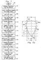
- FIG. 1 there is presented an overview method 100 for performing and using one embodiment of the present invention. A more complete discussion of this method will be presented below.
- the method 100 may use the following components: a shaping device 200 (Fig. 2a), a patch 300 (Fig. 3a), a sizer 402a (Fig. 4a), and a suture hook 520 (Fig. 5).
- a surgeon determines the appropriate size for the patient's left ventricle based on the patient's height, weight, body surface area and other patient specific conditions. Once the patient's appropriate ventricle size has been determined, at step 104, the surgeon can then select the appropriate volume for the shaping device 200.
- the surgeon opens up the chest cavity in a conventional manner. An incision is cut into the myocardial wall of an enlarged heart in step 108.
- the surgeon identifies non-viable tissue.
- the surgeon may remove all or some of the non-viable tissue (i.e., the dyskentic and akinetic areas) of the myocardium.
- a continuous round stitch known in the art as a Fontan stitch, may then be woven into the ventricle, at step 114.
- the stitch produces an annular protrusion, which forms an opening.
- the shaping device 200 may be inserted into the ventricle through this opening.
- the musculature of the myocardium may be pulled over the shaping device to form a left ventricle having a predetermined volume, shape and contour.
- the shaping device 200 may then be compressed and removed at step 120.
- the surgeon may determine the preferred location of and size of the patch 300 which may be placed in the left ventricle.
- the patch 300 is then cut to size in step 124 and secured to the inside of the myocardium in step 126.
- the ventricle is closed by joining the myocardial walls over the patch.
- the Shaping Device :
- Fig. 2a illustrates one embodiment of a shaping device 200.
- the shaping device 200 In an inflated condition, the shaping device 200 is pre-shaped to generally model the appropriate volume and shape of the left ventricle.
- the shape of the normal heart is of particular interest as it dramatically affects the way that the blood is pumped.
- the left ventricle which is the primary pumping chamber, is somewhat conical or apical in shape in that it is longer (long axis longest portion from aortic valve to apex) than it is wide (short axiswidest portion from ventricle wall to septum) and descends from a base with a decreasing cross-sectional circumference to a point or apex.
- the left ventricle is further defined by a lateral and posterior ventricle wall and a septum, which extends between the auricles and the ventricles.
- the pumping of the blood from the left ventricle is accomplished by two types of motion.
- One of these motions is a simple squeezing motion, which occurs between the lateral wall and the septum.
- the squeezing motion occurs as a result of a thickening of the muscle fibers in the myocardium. This compresses the blood in the ventricle chamber and ejects it into the body. The thickness changes as the ventricle contracts. This is seen easily by echocardiogram and can be routinely measured.
- the other type of motion is a twisting or writhing motion, which begins at the apex and rises toward the base.
- the rising writhing motion occurs because the heart muscle fibers run in a circular or spiral direction around the heart. When these fibers constrict, they cause the heart to twist initially at the small area of the apex, but progressively and ultimately to the wide area of the base.
- These squeezing and twisting motions are equally important, as they are each responsible for moving approximately one-half of the blood pumped.
- Fig. 2a there is shown a shaping device 200 that allows the left ventricle to be reconstructed back to a pre-enlarged operating condition.
- the shaping device 200 is generally conical or"tear drop"in shape.
- the length"L"of the shaping device 200 may vary with each patient and will typically be a function of the volume selected for the shaping device. Depending on the patient, thelength"L"may'be in the 7,62cm to 10,16cm ( three to four inch) range to generally match the length of the pre-enlarged left ventricle. A surgeon may select the appropriate volume for the shaping device by estimating the volume of the pre-enlarged left ventricle.
- the appropriate volume of the preenlarged left ventricle for a patient may be estimated to be 50 to 70 cc per square meter of body surface area.
- the shaping device may be of an"appropriate shape"for a patient.
- the shaping device may be of a shape similar to the shape of the left ventricle.
- the back surface 202 of the shaping device 200 is generally shaped as a portion of a sphere, having a radius of. 802*L. At a line"C-C", a width W2 of the shaping device 200 is approximately . 628*L.
- the side surfaces 204a and 204b are combinations of portions of spheres with different radii.
- the side surfaces 204a and 204b have a radius of. S 15L.
- a width W3 of the shaping device 200 is. 435*L. Between the line C-C and the line E-E, the side surfaces 204a and 204b have a radius of. 945L.
- the shaping device 200 narrows from the line designated"E-E"through a line designated as"F-F"to a vertex 206 at point"G". It is important to note that the above discussion is illustrative of only one embodiment of the present invention and is not meant to limit the invention to the above ratios or shapes.
- the shaping device may be an inflatable balloon 201, having a thickness of in the range of 0,0508 cm to 0,2032 cm (02 to. 08 inches), preferably 0,0762 cm (03 inches).
- a distal end of a filler tube 208 may be coupled to a point 207 along the exterior surface of balloon 201.
- the point 207 could be located approximately 1/3 along balloon's 201 length, as illustrated in Fig. 2b.
- the filler tube 208 may be coupled vertex 206.
- Such tubes are well known in the art, and illustratively may be made of materials such as PVC.
- a proximal end of the filler tube 208 may be connected to a fluid reservoir, such as a syringe 210 which may inject a pre-specified amount of fluid into the balloon 201 through the filler tube208.
- a fluid reservoir such as a syringe 210 which may inject a pre-specified amount of fluid into the balloon 201 through the filler tube208.
- a fluid control device such as a stopcock 212.
- the injection of fluid through the filler tube 208 inflates the balloon 201 to an inflated condition, as illustrated in Fig. 2b. Once inflated, the fluid inside the shaping device may be prevented from escaping by locking the stopcock 212. This allows the balloon 201 to stay inflated with the proper volume, shape and contour during the reconstruction procedure.
- the fluid pressure inside the balloon 201 may also be monitored by a pressure transducer, such as a piezoelectric transducer (not shown) coupled to the filler tube 208 with a y-connection (notshown).
- a pressure transducer such as a piezoelectric transducer (not shown) coupled to the filler tube 208 with a y-connection (notshown).
- one lead of the ⁇ -connection would be coupled to a pressure monitor, the other lead would be coupled to the fluid source.
- the pressure monitor could be coupled to a three way stopcock (not shown), which would monitor the pressure on the filler tube side of the three way stopcock.
- the fluid used to fill the balloon 201 may be any one of a number of fluids, such as saline solution or distilled water.
- a sealed balloon containing a silicone gel such as a liquid methyl silicone resin capable of being vulcanized blended with a dimethyl silicone fluid.
- Such gels are available from Applied Silicon Inc. (Ventura, California).
- An embodiment using a sealed balloon would not need an external fluid reservoir, such as syringe210.
- the balloon 201 may be conventionally formed on a mandrel (not shown) having dimensions corresponding to the shape, contour and size of the shaping device.
- the mandrel can be made of metal, glass or a hardened gelatin.
- the mandrel is dipped into a polymer solution, which leaves a thin polymer coating on the mandrel surface. After the polymer has cured, the balloon 201 is removed by peeling the thin coating off the mandrel or by flushing mandrel material out of the shaping device.
- the shaping device of the present invention may be made out of a variety of materials in a number of configurations creating a number of embodiments.
- the shaping device is molded from a thermoplastic polymer such as PVC or polyethylene or a similar material
- the balloon maybe"non- expandable"when inflated.
- the balloon 201 will not significantly expand beyond the original shape.
- several shaping devices might have volumes ranging from100cc to150cc at1Occ increments. If a surgeon predetermines that a patient's pre-enlarged left ventricle was 128cc., then the surgeon might select a non-expandable balloon having a volume of 130cc. A surgeon could also request a custom non-expandable balloon with a volume specifically sized for an individual patient.
- the balloon 201 may significantly expand.
- elastomeric materials may include latex, polyurethane, silicone, and other elastomers sold under the trade names KRATON (Shell Chemical, New York, N. Y.), C-FLEX (Concept Polymer, Largo, Fla.) and SANTOPRENE (Monsanto, St. Louis, Mo.)
- KRATON Shell Chemical, New York, N. Y.
- C-FLEX Concept Polymer, Largo, Fla.
- SANTOPRENE Monsanto, St. Louis, Mo.
- 2c is a section view of an embodiment showing thickened walls of an"expandable balloon"220.
- An insertion or distal end 222 of the balloon 220 has walls at a maximum thickness. From the line A-A, the wall thickness progressively decreases to a vertex 224 at point G. In some embodiments, the vertex 224 connects to the filler tube 208.
- the wall thickness will depend on the expansion range of the balloon. For example, for an expansion of 100 to 150 cc, the thickness of the balloon would vary from.01 "at a thin end to.05"at the thick end. Thus, this size or volume of this embodiment may be controlled by controlling the amount and pressure of the fluid injected into the balloon 220.
- the shaping device could have walls that are relatively thick and are coupled to foam spacers or thermoplastic polymer pads surrounding the exterior of the balloon.
- Fig. 2d there is shown a section view of an embodiment having polymer pads 232a through 2321 coupled to the exterior of a balloon 230.
- polymer pads 232a-2321 provide a plurality of contact points:"A"through”L".
- Contact points"A"though"L if connected, would define a space of approximately the same volume occupied by the balloon 201 (Fig. 2a).
- the balloon 230 would need less fluid for inflation and the polymer pads 232a through 2321 would also provide puncture resistance.
- the shaping device could be a balloon within a balloon.
- Fig. 2e. illustrates such an embodiment.
- a balloon 250 is generally shown in Fig. 2e.
- the balloon 250 comprises a outer balloon 252 and an inner balloon 254.
- the inner balloon 254 is inflatable with a fluid, such as saline solution fluid.
- the inner balloon 254 may be inflated through the filler tube 208.
- a space 256 between the inner balloon 254 and the outer balloon 252 may be pre-filled with a gel 258, such as a silicone gel or saline solution.
- Fig. 2f is a section view illustrating another embodiment of a balloon 260 formed to be puncture resistant.
- the wall 262 proximal to the vertex 206 is progressively thickened to protect the proximal side of the balloon 260 from punctures during the reconstruction procedure.
- the wall 262 could be coupled to protective pads located around the vertex 206 to protect the balloon 260 from punctures.
- the balloon could be made from a thick, self sealing latex rubber. Such latex compounds are well known in the industry.
- Fig. 2g illustrates a shaping device 280 made from a wire skeleton or frame.
- the wire frame could be made from surgical grade stainless steel, titanium, tantalum, or nitinol, which is a commercially available nickel-titanium alloy material that has shape memory and is superelastic. Nitinol medical products are available from AMF of Reuilly, France, and Flexmedics Corp., of White Bear Lake, Minnesota.
- the shaping device 280 illustrated in Fig. 2g is in an expanded condition.
- Running through the center of shaping device 280 is a main shaft 282.
- the main shaft 282 has a distal end 284 and a proximal end286.
- a joint 288 At the distal end 284 is a joint 288.
- Coupled to the joint 288 is a series of back ribs 290a though 290h (only back ribs 290a through 290e are visible in Fig. 2g).
- Back ribs 290a through 290h are connected to front ribs 292a-292h by hinges 294a though 294h (only front ribs 292a-292e and hinges 294a-294e are visible in Fig. 2g).
- front ribs 292a through 292e are connected to a collar 296 through a series of hinges (not shown) radially spaced around collar 296.
- hinges radially spaced around collar 296.
- the use of hinges around collar 296 encourages front ribs 292a-292h to form a convex angle with respect to shaft 282 at collar 296.
- Fig. 2h shows the shaping device 280 in a collapsed position.
- back ribs 290a-290h and front ribs 292a-292h surround shaft 282 as illustrated in Fig. 2j.
- Fig. 2j is a section view cut transversely through shaft 282 and the front ribs 292a-292h.
- a surgeon may slide collar 296 along shaft 282 towards distal end 284. The force exerted on collar 296 will cause the ribs to buckle radially outward as illustrated in Fig. 2g.
- the front ribs 292a-292h will bend under the applied force. Because the front ribs 292a-292h are under stress, they will tend to push the collar 296 towards proximal end 286.
- a lock 294 prevents any desired movement towards proximal end 286.
- the lock 294 is spring (not shown) activated and is designed such that the collar 296 may easily slide over the lock when moving from the proximal end 286 to the distal end284.
- the surgeon may collapse the shaping device 280 by pressing down on lock 294 which will allow the collar 296 to slide past the lock 294 towards the proximal end 286.
- a patch is often used in the ventricle reconstruction procedure.
- a patch is made from sheet material and may be a variety of shapes, including circular, elliptical, or triangular, preferably sized and configured with a shape similar to a Fontan neck, as discussed below.
- an elliptical patch 300 may have a length between 30 and 50 millimeters along a major axis 302 and a width along a minor axis 304 of between 20 and 30 millimeters.
- the preferable thickness of the patch is in the range of. 3 to. 7 mm.
- the water permeability is preferably less than 5 ml per cm sq. per minute at 0,900Pa (120 mm Hg)
- the burst strength of the patch is preferably 30 to 35kg/cm2.
- the45 angle suture retention strength of the patch should be greater than 3 kg.
- the sheet material for the patch 300 may be formed from a biocompatible synthetic material, for example, from polyester, Dacron (Hemoshield) manufactured by the DuPont Corporation, or polytetrafluoroethylene (Gortex).
- the sheet material may also be autologous pericardium, or some other fixedmammalium tissue such as bovine pericardium or porcine tissue.
- the biocompatible synthetic material patch may be collagen impregnated to assist in hemostasis, or it may be sprayed with a hemostatic sealant to achieve better and instantaneous hemostasis.
- the patch may have markings that enable the movement and position of the patch to be postoperatively observed and analyzed under imaging systems, such as Magnetic ResonanceImaging ("MRI"), x-ray machines, fluoroscopy or other external visualization methods, for post-operative clinical evaluation.
- imaging systems such as Magnetic ResonanceImaging ("MRI"), x-ray machines, fluoroscopy or other external visualization methods, for post-operative clinical evaluation.
- MRI Magnetic ResonanceImaging
- x-ray machines x-ray machines
- fluoroscopy fluoroscopy
- Such markings will allow identification of the patch and allow for analysis of the heart's contractility in future post-operative evaluations.
- the markings may be radiopaque.
- Radiopaque markings are made from material that are impenetrable to radiation such as x-rays. Radiopaque markings may be applied to the patch material in a wide variety of methods. For instance, if the patch material is from a woven fabric, then radiopaque threads could be woven into the fabric at regular intervals. Such radiopaque threads could be metal and made from alloys of gold, nitinol, platinum, or stainless steel. Radiopaque threads could also be made of a biocomptabile polymeric material mixed with a metal powder, such as barium sulfate. Radiopaque markings could also be imprinted onto the fabric with radiopaque ink. Such ink is available from Creative Imprints Inc., (Norton, Massachusetts).
- marking the patch 300 might include chemical vapor deposition, physical vapor deposition, electroplating and ion-beam assisted deposition.
- ion-beam assisted deposition an electron beam evaporator is used to create a vapor of atoms that coats the surface of the material.
- Radiopaque threads might interfere with MRI scans because MRI is extremely sensitive to metal and metal can substantially mask MRI signals. However, if metal markings are made sufficiently small, they will show as bands in an MRI scan. Using metal fibers0. 1mm to 0. 05mm to create the grid or pattern by weaving into the patch can make a patch MRI sensitive. Also, the metal can be applied to the patch by ion deposition which could deposit a layer of meta10. 01mm thick onto the patch material. Small tubular strands filled with fatty acids could also be used as be used as MRI sensitive markings. Such strands could be woven into the patch material.
- the markings may be Positron Emission Tomography ("PET”) sensitive by making the markings slightly radioactive.
- PET Positron Emission Tomography
- Such markings would probably only be useful for a relatively short time frame after the procedure because of radioactive decay.
- the markings may also be attached to the material by a variety of mechanical means such as sewing or weaving the markings into patch material or using microclips.
- the markings such as metal threads may also be attached to the material by adhesive means, such as a biocompatible glue.
- Such bio-compatible glues are available from Bioglue, Cryolife Inc.(Kennesaw, Georgia) or Cyanoacrylate, by Loc Tite Corp.
- the markings must be arranged in a pattern that allows post operative evaluation.
- One such pattern is a series of equally spaced substantially parallel lines as illustrated in Fig.
- FIG. 3b Another pattern is a grid of substantially parallel lines as illustrated in Fig. 3c. The distance between these parallel lines may be in standard units, such as 1 centimeter. Another pattern could be in the form of concentric circles, as illustrated in Fig. 3d. Yet, another pattern could be a series of lines radiating from a single point at, for instance, a set angle apart. Such a pattern is illustrated in Fig. 3e.
- Fig. 4a there is illustrated a set of sizers 402a-402d.
- the sizers 402a-402d are shaped to be the approximate size of the patch 300 (Fig. 3a). Similar to the patch, the sizers402a-402d will be of various geometries, length and width combinations. For illustrative purposes, the sizers 402a402d discussed herein will be elliptical in shape. For posterior repairs to the ventricle, however, the sizers may have a general triangular shape. Referring back to Fig. 4a, the length of the sizers along a major axis 403 may be in the range of 2 to 7 cm in length.
- the length along a minor axis 405 may be 1 to 5 cm in length.
- the sizers may have a connection 406 for attachment to a handle 404 (Fig. 4b).
- the sizers 402a402d can be made out of plastic or stainless steel or any rigid material. Four sizers 402a-402d are illustrated in Fig. 4a, however, any number of sizers in a variety of could be provided.
- the handle 404 may also be made from stainless steel, plastic or any other suitable material.
- the handle 404 includes a shaft 408 having a proximal end 410 and a distal end 412.
- the distal end 412 couples to the connection 406 of the sizers 402a-402d.
- the proximal end 410 is coupled to a hand grip 414.
- the hand grip 414 is sized to fit a human hand. Such hand grips are wellknown in the art.
- a surgeon may connect any of the sizers 402a-402d to the handle 404.
- the use of handle 404 with a sizer allows the surgeon to easily estimate the size of the opening to be patched by holding the sizer up to and into the opening. If the sizer is to small, another one may be selected. This process may be repeated until the surgeon feels he has a sizer of the correct shape and size.
- the sizer may be placed on material and be used as a template to cut the patch 300 to the appropriate size.
- Fig. 4c is a section view illustrating the connection 406 between the distal end 412 of shaft 408 and the sizer 402a.
- the connection 406 comprises a circular opening 422.
- Embedded in the walls of the opening 422 and running through the opening 422 is a rod 420.
- the rod 420 may be made of surgical stainless steel or another appropriate rigid material.
- the distal end412 includes a slot 425 with angular walls forming two flanges 423a and 423b. At the base of the slot 425 is a circular groove.
- the circular grove runs generally parallel to the slot 425 and has an interior diameter slightly larger than the exterior diameter of rod 420.
- the base of the slot 425 is slightly smaller than the diameter of rod 420.
- flanges 423a and 423b slide over rod 420 until rod 420 is in the circular groove.
- flanges 423a and 423b are "snapped"over rod 420, and thus, will keep rod 420 in the cylindrical groove.
- the sizer 402a may rotate with respect to shaft 408.
- the sizer 402a may be removed from handle 404 by pulling on the sizer 402a which causes a sufficient amount of force on rod 420 to lift flanges 423a and 423b over rod 420.
- connection 406 may be a screw connection.
- the sizers may have a cutting edge which can be used to cut the patch 300 to the appropriate shape.
- a sizer 430 is shown connected to the handle408.
- the sizer 430 may have a ridge 432 concentric to the shape of the sizer 430.
- the ridge 432 allows a surgeon to accurately estimate the size of the opening by placing the ridge432 into the opening.
- the sizer 430 may also have a circumferential flange or lip 434 around the perimeter of the sizer to assist in defining the patch size.
- the patch will typically be slightly larger than the size of the opening.
- the width of the lip 434 will preferably have a constant width around its circumference, typically in the range between 5 and 8 centimeters.
- a cutting edge 436 may also be coupled to the perimeter of the lip.
- the surgeon may use the sizer as illustrated in Fig. 4d to estimate the size of the opening, remove the sizer 430 from the handle 408, turn the handle over with respect to the handle 408, and reattach the sizer 430 to the handle 408.
- the cutting edge 436 may then be used to cut the patch material to the correct size and shape by pressing the cutting edge into the patch material.
- a set of cutting dies could also be provided which corresponds to the set of sizers.
- a set of pre-cut patches could be provided, each pre-cut patch corresponding to a particular sizer in the set of sizers.
- the use of pre-cut patches would eliminate the need to cut the patch material to the required shape.
- the pre-cut patches may also have pre-printed suture lines which may be used as a guide for the surgeon when attaching the patch to the heart.
- Fig. 4e illustrates an embodiment of a sizer 440 having a protrusion 442 concentric to the shape of the sizer 440.
- the protrusion 442 may also be used to define a suture line on the patch material by pressing the protrusion 442 against the patch material causing an indentation in the patch material which the surgeon can use as a guide to suture the patch.
- Fig.4f illustrates embodiment of a sizer 450 having a slot or groove 452 concentric to the shape of the sizer.
- the groove 452 may be used by the surgeon to define a suture line by allowing the surgeon to use a marking instrument, such as a pen, to trace the suture line on the patch material.
- Fig. 4g illustrates yet another embodiment of a sizer.
- the sizer 460 may be a malleable wire 462 coupled to movable legs 464a-464d (464a and 464b are visible in Fig. 4g).
- the moveable legs 464a-464d are coupled to a handle 466.
- the handle 466 includes a shaft 468 having a proximal end 470 and a distal end 472.
- the distal end 472 couples to the movable legs 464a-464d.
- the proximal end 470 is coupled to a hand grip 474.
- the hand grip 474 is similar to the handgrip 414 of Fig. 4b.
- FIG. 4h is a section view of the sizer 460 cut through the movable legs 464a-464d.
- the malleable wire 462 may be manipulated by the surgeon into any appropriate shape. Additionally, because one end 476 of the malleable wire 462 is free to slide past the moveable legs 464a and 464d, the perimeter of the shape formed by the wire may be lengthened or shortened as desired.
- the patch holder 500 comprises a patch plate 502 coupled to legs 504a-504d (504a and 504b are visible in FigSa).
- the legs 504a-504d are coupled to a handle 506, which is similar to handle 466 discussed above.
- the patch plate 502 has an adhesive means on side 508, such as an adhesive backing or nylon hooks, which temporarily adheres to the patch.
- the surgeon may use patch holder 500 to place the patch into the opening, after suturing has begun, the patch holder may be removed, leaving the patch in place.
- the suture hook 520 is"L"shaped and made of stainless steel, plastic or another rigid material.
- the suture hook 520 has a long leg 522 which may be approximately 15,24cm (inches long) Coupled to long leg 522, is short leg 524 which may be in the range of 0,3175cm to 0,635cm (one-eighth to one-quarter inch long).
- the suture hook 520 is adapted to be used to pull up on the sutures in the patch 300 to secure the patch 300 to the heart.
- a kit 600 for surgically reshaping the left ventricle of the heart is illustrated in Fig. 6.
- the kit 600 may include any of the components discussed above, including the balloon 201 coupled to the syringe 210, a set of the sizers 402 in various shapes and sizes, a handle 404 to attach to the sizers 402, material 602 for creating the patch 300 (not shown), the suture hook 520 and, the patch holder 500 (not shown).
- the components of the kit 600 may be packaged in a sterile manner as known in the relevant art.
- the intent of the procedure initially is to remove that portion of the wall, which is not capable of contracting.
- Such portions include the scarreddyskinetic segments, which are easy to see visually, and may also include akinetic segments, which do not contract.
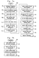
- a surgeon determines the appropriate size for the patient's left ventricle based on the patient's height, weight, body surface area and other patient specific conditions (as discussed previously in reference to Fig. 2a). Once the patient's appropriate ventricle size has been determined, at step 704, the surgeon can then select the appropriate volume for the shaping device.
- step 706 the patient's chest cavity is opened up in a conventional manner.
- step 708 an incision is cut into the myocardial wall of the dilated heart. If the surrounding tissue isdyskinetic, it will typically be formed entirely of thin, elastic scar tissue. It is the elasticity of this scar tissue, which causes the detrimental ballooning, or bulging effects previously discussed.
- step710 a determination as to where the akinetic portions of the tissue begin and end must be made. The determination between viable and non viable tissue can be made by multiple methods, including: visual inspection, electrical methods, marking with dyes, echocardiography, radionuclear imaging, and palpation of a beating heart.
- the electrical methods might include the use of anelectromyogram which detects electrical impulses from active tissue to distinguish between the akinetic and viable tissue.
- Positron Emission Tomography (PET) scanning, Single Proton Emissions Computer Tomography and Electrical Mapping Electrophysiology are all other examples of a method to determine viable tissue from akinetic tissue with by electrical means.
- Electrical Mapping Electrophysiology a catheter is inserted into the heart to find areas void of electrical activity.
- Marking with dyes can be accomplished by staining the myocardium tissue with a dye that adheres to viable tissue and does not adhere to scar tissue.
- Triphenyltetrazolium chloride, Tropinin I or T, and Creatine Kinase are all examples of dyes that perform this marking function.
- the portion of the tissue in the ventricle and septal walls may be excised from the epicardium from the incision to the borderline separating akinetic tissue from viable tissue.
- This border between akinetic and viable tissue becomes the preferred location of the patch and forms an imaginary circumferential line between the non viable areas and viable areas of the myocardium.
- a continuous Fontan stitch may be placed in proximity to the line, along the long axis of the heart.
- the Fontan stitch produces an annular protrusion, which forms a neck relative to the circumferential line.
- the annular protrusion may be further defined by placing a rim support around its perimeter. This neck initially may have a round circular configuration.
- a second Fontan stitch may be placed 90 degrees from the initial stitch along the short axis of the heart. Other stitches may be placed as needed to form the heart to the shaping device. The stitch will serve to shape the heart along the short axis of the heart if needed.
- the shaping device 200 may then be inserted into the ventricle.
- the shaping device 200 is then inflated or expanded, the volume of which is equivalent to the appropriate volume of the ventricle for the patient.
- the shaping device 200 provides the model upon which the ventricle can be shaped and contoured through the use of the Fontan suture in step 720.
- the Fontan suture may then tightened with the aid of the suture hook 520, in step 722.
- the suture or sutures are tightened, the musculature of the myocardium will form the physiologically correct volume, shape and contour over the shaping device.
- the appropriately oval-shaped opening in the neck defines the area where the patch will be placed.
- the size of the opening in the neck formed by the Fontan stitch will vary from patient to patient.
- the surgeon should determine the size of the patch to be used (step 726). To determine the appropriate size of the patch, the surgeon may connect any of the sizers 402a402d to the handle 404 to measure the size of the opening, and thus, the size patch 300 that is needed to fit into the neck formed by the Fontan stitch or stitches. In step 728, the surgeon may then construct a patch.
- the sizer can be placed on the patch and be used as a template to cut the patch 300 to the appropriate size.
- a surgeon may select a precut patch.
- continuous or interrupted sutures can be threaded through the rim covered annular protrusion.
- the rim covering acts as a large continuous pledget along the perimeter.
- another suture method can be placement of mattressed braided sutures over a pericardial strip from outside the ventricle to its interior through the inner oval of the patch. This procedure can be done in conjunction with other procedures such as ; Mitral valve repair, ablation of ventriculararrhythmias for treatment of refractory ischemic ventricular tachycardia.
- the suture line can be sprayed with a hemostatic agent or an agent can be applied to achieve better and instantaneous hemostasis.
- the operative site can be closed by joining or folding over the myocardial walls. Care should be taken not to distort the right ventricle by folding the septum wall over the ventricular wall.
- the lateral wall can be disposed interiorly of the septum wall so a majority of the force on the patch is diverted to the lateral wall.
- These walls can be overlapped in close proximity to the patch in order to avoid creating any cavity between the patch and the walls.
- the patient can be weaned off bypass usually with minimal, if anyinotropic support.Decannulasation may be accomplished with conventional methods (step 736).
- the human heart contains an electrical conduction system which sends electrical impulses to spark the heart muscle into regular cycles of contraction.
- This conduction system includes aSinoatrial node (SA node), Atrioventricular Node (AV node), and Purkinie Fibers which act as conduits for the electrical pulses.
- SA node is located in the right atrium.
- the electrical impulse leaves the SA node and travels to the right and left Atria, causing them to contract together. This takes. 04 seconds.
- the electrical impulse has now traveled to the Atrioventricular Node (AV node).
- the electrical impulse now goes to the Bundle of His, then it divides into the Right and Left Bundle Branches where it rapidly spreads usingPurkinje Fibers to the muscles of the Right and Left Ventricle, causing them to contract at the same time.
- ventricular restoration may compromise the conduction system due to the fact that a ventricle portion has been severed or excluded, the pacing or rhythm of the impulses between the right and left ventricles of the heart may get out of synchronization after ventricular restoration.
- This asynchronous pacing contributes to a reduced output by the left ventricle.
- restoring or assuring synchronization would assist the reconstructed left ventricle to maximize the output of the left ventricle.
- Synchronization may be restored or controlled by implanting a pacemaker or aBiventricular pacing device ("BVP") before closing the chest cavity.
- BVP aBiventricular pacing device
- a pacemaker comprises: (1) an implantable controller that sets the heart rate to the desired interval, and(2) two leads that deliver electrical impulses to specific regions of the heart (i. e., one lead is placed in the right atrium and the second lead in right ventricle) to artificially cause contractions of the ventricle at the appropriate time and synchronization.
- BVPs have a third lead designed to conduct signals directly into the left ventricle.
- one lead is placed in the right atrium, the second lead in right ventricle and third lead is placed to pace the left ventricle (i. e., in a tributary of the coronary sinus in the left ventricle).
- simultaneous electrical impulses are given to both left and right ventricles so the time delay in traveling of electrical impulse is significantly reduced which aids in restoring the normal physiology of the heart and improves the pumping action of the heart.
- Pacemakers and biventricular pacing devices are available fromMedtronic, Inc. (Minneapolis, Minnesota), Guidant Corporation (Menlo Park, California), and St. Jude Medical Inc. (St. Paul, Minnesota).
- the mortality associated with ventricular restoration is primarily from sudden death caused from extremely fastarrthymias.
- the higher risk of arrthymias may be caused from the removal of a portion of the left ventricle. This risk may be prevented by implanting a defibrillator at the time of the ventricle restoration.
- the automatic implantable cardioverter/defibrillator is commonly referred to as an AICD.
- the AICD is a device that is similar to a pacemaker, but continuously monitors the heart rhythm. If the AICD detects an abnormally fast or slow heart rhythm, it either electrically paces the heart very fast or delivers a small electrical shock to the heart to convert the heart rhythm back to normal.
- Some BVP devices have defibrillators built into the circuitry that controls the pacing. Implanting abi-ventricular pacing device with defibrillator after surgical ventricular restoration will not only optimize the output of the ventricle but also prevent many sudden deaths.
- closure of the chest cavity may be accomplished in step 740 by conventional methods.
- the device used in surgical procedures to reconstruct an enlarged left ventricle of a human heart comprises a sharper, having a size and shape substantially similar to the size and shape of an appropriate left ventricle, wherein the size of the appropriate left ventricle is less then the size of the enlarged left ventricle, and wherein the shaper is adapted to be temporarily placed into the enlarged left ventricle during a surgical procedure.
- the shaper may comprise an expandable balloon, such that when the balloon is in a substantially inflated condition, the balloon is a size and shape substantially equal to the size and shape of an appropriate left ventricle.
- the shaper may also comprise an expandable balloon, such that when the balloon is in a substantially inflated condition, the balloon is a size and shape substantially equal to the size and shape of an appropriate left ventricle, wherein when the balloon is in an inflated condition, the balloon cannot be substantially expanded.
- the shaper may comprise an expandable balloon, such that when the balloon is in a substantially inflated condition, the balloon is a size and shape substantially equal to the size and shape of an appropriate left ventricle, wherein the balloon is in an inflated condition, the balloon maintains the shape of an appropriate left ventricle while being further inflated.
- the shaper comprises in one embodiment an expandable balloon, such that when the balloon is in a substantially inflated condition, the balloon is a size and shape substantially equal to the size and shape of an appropriate left ventricle, wherein the balloon is filled with fluid.
- the shaper comprises in another embodiment, an expandable balloon, such that when the balloon is in a substantially inflated condition, the balloon is a size and shape substantially equal to the size and shape of an appropriate left ventricle, wherein the balloon is filled with fluid, wherein the fluid comprises a gel.
- the shaper may comprise an expandable balloon, such that when the balloon is in a substantially inflated condition, the balloon is a size and shape substantially equal to the size and shape of an appropriate left ventricle, wherein the balloon is filled with fluid, wherein the fluid comprises a gel, wherein the gel comprises silicone.
- the shaper may also comprise an expandable balloon, such that when the balloon is in a substantially inflated condition, the balloon is a size and shape substantially equal to the size and shape of an appropriate left ventricle, further comprising:
- the shaper comprises in one embodiment an expandable balloon, such that when the balloon is in a substantially inflated condition, the balloon is a size and shape substantially equal to the size and shape of an appropriate left ventricle, further comprising:
- the shaper comprises an expandable balloon, such that when the balloon is in a substantially inflated condition, the balloon is a size and shape substantially equal to the size and shape of an appropriate left ventricle, further comprising:
- the shaper comprises an expandable balloon, such that when the balloon is in a substantially inflated condition, the balloon is a size and shape substantially equal to the size and shape of an appropriate left ventricle, further comprising:
- the shaper may also comprises an expandable balloon, such that when the balloon is in a substantially inflated condition, the balloon is a size and shape substantially equal to the size and shape of an appropriate left ventricle, further comprising:
- the shaper comprises a wire mesh of a predetermined shape.
- the wire mesh may comprise nitinol.
- the device may have substantially a non-circular shape.
- the device of clause may have substantially a non-circular shape, wherein the shaper has a short and a long axis.
- the device may have substantially a non-circular shape, wherein the shaper has a short and a long axis, and wherein the ratio of short to long axis is about 0.5.
- the shaper comprises a substantially ellipsoid shape.
- the shaper is substantially conical in shape.
- the shaper is substantially pear shaped.
- the shaper is substantially tear drop shaped.
- the device used in surgical procedures to reconstruct an enlarged left ventricle of human heart comprises:
- the shaper may comprise an expandable balloon, such that when the balloon is substantially inflated, the balloon defines the size and shape of appropriate left ventricle.
- the shaper may comprise an expandable balloon, such that when the balloon is substantially inflated, the balloon defines the size and shape of appropriate left ventricle, wherein the balloon is in an inflated condition, the balloon maintains its shape which defines the intended left ventricle, while, being further inflated.
- the device for use in left ventricle reconstruction surgery comprises:
- the device for use in left ventricle reconstruction surgery comprises
- the device for use in left ventricle reconstruction surgery comprises:
- the device for use in left ventricle reconstruction surgery comprises:
- a ventricular patch as referred to in Claim 12, adapted for placement into the left ventricle of a heart, comprises:
- the movement of the patch may be measured along a longitudinal axis and a transverse axis of the patch.
- the biocompatible material may be selected from the group comprising bovine pericardium, porcine tissue, and polyester.
- the biocompatible material is collagen impregnated.
- At least some of the markings may be radio-paque.
- the markings are radio-paque
- the biocompatible material is formed of threads produced by co-extruding the fabric with radiopaque polymeric material.
- the markings are radio-paque
- the biocompatible material is formed of threads made from a mixture of polymeric material and barium sulfate.
- At least some of the markings are metal threads.
- At least some of the markings are metal threads selected from the group comprising gold, nitinol, platinum, and stainless steel.
- At least some of the markings are radio-paque, and at least some of the markings are imprinted on the material with radiopaque ink.
- At least some of the markings may be MRI scan sensitive.
- At least some of the markings may be coupled to the material using mechanical means.
- At least some of the markings may be coupled to the material using adhesive means.
- At least some of the markings may be imprinted by ion deposition.
- At least some of the markings may be form a plurality of equally spaced substantially parallel lines.
- At least some of the markings may be form a plurality of equally spaced substantially parallel lines, and wherein the spacing between at least some of the parallel lines is one centimeter.
- At least some of the markings may be form a uniform grid of horizontal and vertical lines.
- At least some of the markings may be form a pattern of equally spaced concentric circles having different diameters.
- At least some of the markings may be form a pattern of lines radiating from a single point.
- the invention according to claim 12 and one of the dependent claims relates to a pre-fabricated, sterile kit for use during left ventricle reconstructive surgery to provide tools and apparatus to interoperatively construct a heart patch, reconstruct a left ventricle, and close an incision using the heart patch, the kit comprising:
- the kit further comprises:
- the kit further comprises:
- the kit may further comprising a cutter die for cutting out a portion of the bio-compatible material along a perimeter of one sizing template (not claimed).
- the hit further comprises a suture hook (not claimed).
- the hit further comprises a handle, wherein each sizing template is adapted to be coupled to the handled (not claimed).
- the invention relates to a pre-fabricated, sterile kit for use during left ventricle reconstructive surgery to provide tools and apparatus to interoperatively construct a heart patch, reconstruct a left ventricle, and close an incision using the heart patch, the kit comprising:
- the kit may further comprise:
- the kit may further comprise:
- the kit may further comprise a cutter die for cutting out a portion of the bio-compatible material along a perimeter of the one such sizing template.
- the kit further comprise a suture hook.
- the kit may further comprise a handle, wherein each sizing template is adapted to be coupled to the handle.
- the invention relates to a pre-fabricated, sterile kit for use during left ventricle reconstructive surgery to provide tools and apparatus to interoperatively construct a heart patch, reconstruct a left ventricle, and close an incision using the heart patch, the kit comprising:
- the kit may further comprise:
- the kit may further comprise:
- the kit may further comprise a cutter die for cutting out a portion of the bio-compatible material along a perimeter of the one such sizing template (not claimed).
- the kit may further comprise a suture hook (not claimed).
- the kit may further comprise a handle, wherein each sizing template is adapted to be coupled to the handle (not claimed).
Landscapes
- Health & Medical Sciences (AREA)
- Cardiology (AREA)
- Oral & Maxillofacial Surgery (AREA)
- Transplantation (AREA)
- Engineering & Computer Science (AREA)
- Biomedical Technology (AREA)
- Heart & Thoracic Surgery (AREA)
- Vascular Medicine (AREA)
- Life Sciences & Earth Sciences (AREA)
- Animal Behavior & Ethology (AREA)
- General Health & Medical Sciences (AREA)
- Public Health (AREA)
- Veterinary Medicine (AREA)
- Prostheses (AREA)
- Electrotherapy Devices (AREA)
- Measurement And Recording Of Electrical Phenomena And Electrical Characteristics Of The Living Body (AREA)
Abstract
Description
- This invention relates generally to apparatus for addressing cardiomyopathy, and more specifically apparatus for restoring the architecture and normal function of a mammalian heart.
- The function of a heart in an animal is primarily to deliver life-supporting oxygenated blood to tissue throughout the body. This function is accomplished in four stages, each relating to a particular chamber of the heart. Initially deoxygenated blood is received in the right auricle of the heart. This deoxygenated blood is pumped by the right ventricle of the heart to the lungs where the blood is oxygenated. The oxygenated blood is initially received in the left auricle of the heart and ultimately pumped by the left ventricle of the heart throughout the body. It can be seen that the left ventricular chamber of the heart is of particular importance in this process as it is relied upon to pump the oxygenated blood initially through an aortic valve into and ultimately throughout the entire vascular system.
- The amount of blood pumped from the left ventricle divided by the amount of blood available to be pumped is referred to as the ejection fraction of the heart. Generally, the higher the ejection fraction the more healthy the heart. A normal heart, for example may have a total volume of one hundred milliliters and an ejection fraction of 60 percent. Under these circumstances, 60 milliliters of blood are pumped with each beat of the heart. It is this volume in the normal heart of this example that is pumped with each beat to provide nutrients including oxygen to the muscles and other tissues of the body.
- The heart is part of the body tissue, and the heart muscle also requires oxygenated blood. Its normal function is greatly upset by clotting or closure of the coronary arteries. When the coronary arteries are blocked, an associate portion of the heart muscle becomes oxygen-starved and begins to die. This is clinically referred to as a heart attack. Ischemic cardiomyopathy typically occurs as the rest of the heart dilates in an attempt to maintain the heart's output to the body.
- As the ischemia progresses through its various stages, the affected myocardium dies losing its ability to contribute to the pumping action of the heart. The ischemic muscle is no longer capable of contracting so it cannot contribute to either squeezing or twisting motion required to pump blood. This non-contracting tissue is said to be"akinetic."In severe cases the akinetic tissue, which is not capable of contracting, is elastic so that blood pressure tends to develop a bulge or expansion of the chamber. In this situation, this muscle tissue is not only akinetic, in that it does not contribute to the pumping function, but it is in fact"dyskinetic,"in that it detracts from the pumping function. This situation is particularly detrimental as the heart loses even more of its energy due to pumping the blood to the bulge instead of through the aorta.
- After a heart attack, the body seems to realize that with a reduced pumping capacity, the ejection fraction of the heart is automatically reduced. For example, the ejection fraction may drop from a normal 60 percent to 20 percent. Realizing that the body still requires the same volume of blood for oxygen and nutrition, the body causes its heart to dilate or enlarge in size so that the smaller ejection fraction pumps about the same amount of blood. As noted, a normal heart with a blood capacity of seventy milliliters and an ejection fraction of 60 percent would pump approximately 42 milliliters per beat. The body seems to appreciate that this same volume per beat can be maintained by an ejection fraction of only 30 percent if the ventricle enlarges to a capacity of 140 milliliters. This increase in volume, commonly referred to as "remodeling", not only changes the volume of the left ventricle, but also its shape. The heart becomes greatly enlarged. An enlarged heart will tend to change its architecture from the normal conical or apical shape, to a generally spherical shape.
- On the level of the muscle fibers, it has been noted that enlargement or dilation of the heart causes the fibers to reorient themselves so that they are directed away from the inner heart chamber containing the blood. As a consequence, the fibers are poorly oriented to accomplish even the squeezing action, as the lines of force become less perpendicular to the heart wall. This change in fiber orientation occurs as the heart dilates and moves from its normal elliptical shape to its dilated spherical shape. The spherical shape further reduces pumping efficiency since the fibers which normally encircle the apex to facilitate writhing are changed to a more flattened formation as a result of these spherical configurations. The resulting orientation of these fibers produces lines of force, which are also directed laterally of the ventricle chamber. Thus, the dilation and resulting spherical configuration greatly reduces contraction efficiency.
- Perhaps the most notable symptom of ischemic cardiomyopathy is the reduction in the ejection fraction which may diminish, for example, from a normal 60 percent to only 20 percent. This results clinically in fatigue and in an inability to do stressful activities that require an increase in output of blood from the heart. The output of blood by the enlarged heart at rest is kept normal, but the capacity to increase output of blood during stress (i. e., exercise, walking) is significantly reduced. Of course, the change in architecture has a dramatic effect on wall thickness, radius, and stress on the heart wall. In particular, it will be noted that absent the normal conical shape, the twisting motion of the heart, which can account for as much as one half of the pumping action, is lost. As a consequence, the more spherical architecture must rely almost totally on the lateral squeezing action to pump blood. This lateral squeezing action is inefficient and very different from the more efficient twisting action of the heart. The change in architecture of the heart will also typically change the structure and ability of the mitral valve to perform its function in the pumping process. Valvular insufficiency can also occur due to dilatation.
- Although the dilated heart may be capable of sustaining life, it is significantly stressed and rapidly approaches a stage where it can no longer pump blood effectively. In this stage, commonly referred to as congestive heart failure, the heart becomes distended and is generally incapable of pumping blood returning from the lungs. This further results in lung congestion and fatigue. Congestive heart failure is a major cause of death and disability in the United States with approximately 400,000 new cases annually.
- Following coronary occlusion, successful acute reprefusion bythrombolysis, (clot dissolution)percutaneous angioplasty, or urgent surgery can decrease early mortality by reducingarrhythmias and cardiogenic shock. It is also known that addressing ischemic cardiomyopathy in the acute phase, for example with reperfusion, may salvage the epicardial surface. Although the myocardium may be rendered akinetic, at least it is notdyskinetic. Post-infarction surgical re-vascularation can be directed at remote viable muscle to reduce ischemia.
- However, it does not address the anatomical consequences of the akinetic region of the heart that is scarred. Despite these techniques for monitoring ischemia, cardiac dilation and subsequent heart failure continue to occur in approximately 50 percent of post-infraction patients discharged from the hospital.
- Various surgical approaches have been tried to treat the dilation of the ventricle by primarily reducing the ventricular volume. Us Patent
5,192,314 describes a synthetic intraventricular implat device adapted to be surgically secured in a ventricle of the heart of a patient to reduce end-diastolic volume, pressure and wall stress, and to subsequently increase ejection fraction and cardiac output. Some of these procedures involve removing or excludingdyskinetic and akinetic regions of the heart, then surgically joining the viable portions of the myocardial walls, typically with the use of a patch surgically placed in the walls using a Fontan stitch. - Typically, the exact placement of the patch has been visually determined using only a visual indication where the typically white scar tissue meets the typically red normal tissue. Location of the patch has been facilitated in a further procedure where a continuous suture has been placed around the ventricular wall to define a neck for receiving the patch. The neck has been formed in the white scar tissue rather than the soft viable muscle. This procedure has relied on cardioplegia methods to stop the beating of the heart and to aid in suture placement.
- These surgical procedures have been met with some success as the ejection fraction has been increased, for example, from 24 percent to 42 percent. However, despite this level of success, it is often difficult for the surgeon to reconstruct the shape and size of the left ventricle. If the reconstructed ventricle is too small, the patient will not be able to pump enough oxygenated blood. If the reconstructed ventricle is too large, the ejection fraction may diminish. In addition to the size, the shape of the reconstructed ventricle is also important. If the left ventricle is reconstructed in a spherical shape, a twisting motion of the heart about its apex, which can account for as much as one half of the pumping action, is lost. As a consequence, the spherical shaped reconstructed ventricle must rely almost totally on the lateral squeezing action to pump blood. This lateral squeezing action is inefficient and very different from the more efficient twisting action of the heart. What is needed, therefore is a reliable method and apparatus to allow a surgeon to reconstruct the left ventricle to the appropriate shape, size and contour.
- In response to these and other problems, an improved apparatus is provided for restoring the geometry of the left ventricle to counteract the effects of cardiac remodeling. The present invention according to claim 1 provides an apparatus to reconstruct an enlarged left ventricle of a human heart, using a shaper, having a size and shape substantially equal to the size and shape of an appropriate left ventricle, wherein the shaper is adapted to be temporarily placed into the enlarged left ventricle during a surgical procedure. According to independent claim 12 a ventricular patch adapted for placement into the left ventricle of a heart made from a sheet of biocompatible material, and having a plurality of markings coupled to the sheet, wherein the markings are configured in distinct patterns for post operatively evaluating movement of the patch and a handle and a series of sizing templates adapted to be coupled to the handle.
- Such components are also presented as a kit for use during ventricular restoration surgery.
-
- Fig. 1 illustrates one embodiment of a process utilizing several aspects of the present invention.
- Fig. 2a is a side view of one embodiment of a shaping device.
- Fig. 2b is a side view of a balloon embodiment of a shaping device.
- Fig. 2c is a section view of another balloon embodiment of a shaping device.
- Fig. 2d is a section view of another balloon embodiment of a shaping device.
- Fig. 2e is a section view of another balloon embodiment of a shaping device.
- Fig. 2f is a section view of another balloon embodiment of a shaping device:
- Fig. 2g is a side view of a wire frame embodiment of a shaping device in an expanded condition.
- Fig. 2h is a side view of a wire frame embodiment of a shaping device in an expanded condition.
- Fig. 2j is a section view cut transversely through the embodiment of Fig. 2h.
- Fig.3a is a top view of one embodiment of a patch.
- Fig. 3b is a top view of one embodiment of markings which may be coupled to the patch of Fig. 3a.
- Fig.3c is a top view of one embodiment of markings which may be coupled to the patch of Fig. 3a.
- Fig. 3d is a top view of one embodiment of markings which may be coupled to the patch of Fig.3a.
- Fig. 3e is a top view of one embodiment of markings which may be coupled to the patch of Fig.3a.
- Fig. 4a is a top view of one embodiment of a set of sizers.
- Fig. 4b is a top view of one embodiment of a handle to be used with the set of sizers illustrated in Fig. 4a.
- Fig. 4c is a detailed section view illustrating a connection between the handle and a sizer.
- Fig. 4d is a section view of one embodiment of a sizer.
- Fig. 4e is a section view of one embodiment of a sizer.
- Fig. 4f is a section view of one embodiment of a sizer.
- Fig. 4g is a top view of one embodiment of a sizer made of malleable wire.
- Fig. 4h is a side view of the sizer illustrated in Fig. 4g.
- Fig. 5a is a top view of one embodiment of a patch holder.
- Fig. 5b is a top view of one embodiment of a suture hook.
- Fig. 6 is a top view of one embodiment of a kit for surgically reshaping a ventricle.
- Fig. 7a illustrates one embodiment of a process utilizing several aspects of the present invention.
- Fig. 7b is a continuation of the process illustrated in Fig. 7a.
- An overview method of one embodiment is presented which introduces the primary components of one embodiment. A detailed discussion of these components then follows. Finally, a method of using the components is discussed in detail.
- Turning to Fig. 1, there is presented an
overview method 100 for performing and using one embodiment of the present invention. A more complete discussion of this method will be presented below. - The
method 100 may use the following components: a shaping device 200 (Fig. 2a), a patch 300 (Fig. 3a), asizer 402a (Fig. 4a), and a suture hook 520 (Fig. 5). Referring back to Fig. 1, atstep 102, a surgeon determines the appropriate size for the patient's left ventricle based on the patient's height, weight, body surface area and other patient specific conditions. Once the patient's appropriate ventricle size has been determined, atstep 104, the surgeon can then select the appropriate volume for theshaping device 200. Atstep 106, the surgeon opens up the chest cavity in a conventional manner. An incision is cut into the myocardial wall of an enlarged heart instep 108. Atstep 110, the surgeon identifies non-viable tissue. Atstep 112 the surgeon may remove all or some of the non-viable tissue (i.e., the dyskentic and akinetic areas) of the myocardium. A continuous round stitch, known in the art as a Fontan stitch, may then be woven into the ventricle, atstep 114. The stitch produces an annular protrusion, which forms an opening. Atstep 116, theshaping device 200 may be inserted into the ventricle through this opening. Atstep 118, the musculature of the myocardium may be pulled over the shaping device to form a left ventricle having a predetermined volume, shape and contour. Theshaping device 200 may then be compressed and removed atstep 120. Atstep 122, with the aid of thesizer 402a, the surgeon may determine the preferred location of and size of thepatch 300 which may be placed in the left ventricle. - The
patch 300 is then cut to size instep 124 and secured to the inside of the myocardium instep 126. Atstep 128, with thepatch 300 suitably placed, the ventricle is closed by joining the myocardial walls over the patch. - Fig. 2a illustrates one embodiment of a
shaping device 200. In an inflated condition, theshaping device 200 is pre-shaped to generally model the appropriate volume and shape of the left ventricle. - The shape of the normal heart is of particular interest as it dramatically affects the way that the blood is pumped. The left ventricle which is the primary pumping chamber, is somewhat conical or apical in shape in that it is longer (long axis longest portion from aortic valve to apex) than it is wide (short axiswidest portion from ventricle wall to septum) and descends from a base with a decreasing cross-sectional circumference to a point or apex. The left ventricle is further defined by a lateral and posterior ventricle wall and a septum, which extends between the auricles and the ventricles. The pumping of the blood from the left ventricle is accomplished by two types of motion. One of these motions is a simple squeezing motion, which occurs between the lateral wall and the septum. The squeezing motion occurs as a result of a thickening of the muscle fibers in the myocardium. This compresses the blood in the ventricle chamber and ejects it into the body. The thickness changes as the ventricle contracts. This is seen easily by echocardiogram and can be routinely measured.
- The other type of motion is a twisting or writhing motion, which begins at the apex and rises toward the base. The rising writhing motion occurs because the heart muscle fibers run in a circular or spiral direction around the heart. When these fibers constrict, they cause the heart to twist initially at the small area of the apex, but progressively and ultimately to the wide area of the base. These squeezing and twisting motions are equally important, as they are each responsible for moving approximately one-half of the blood pumped. Turning now to Fig. 2a., there is shown a
shaping device 200 that allows the left ventricle to be reconstructed back to a pre-enlarged operating condition. When the surgeon uses shapingdevice 200 as a guide in reconstructing the left ventricle, the reconstructed heart can be formed closer to the size and shape of the pre-enlarged heart. Consequently, the heart performs better post operatively than with conventional methods. As illustrated, theshaping device 200 is generally conical or"tear drop"in shape. The length"L"of theshaping device 200 may vary with each patient and will typically be a function of the volume selected for the shaping device. Depending on the patient, thelength"L"may'be in the 7,62cm to 10,16cm ( three to four inch) range to generally match the length of the pre-enlarged left ventricle. A surgeon may select the appropriate volume for the shaping device by estimating the volume of the pre-enlarged left ventricle. The appropriate volume of the preenlarged left ventricle for a patient may be estimated to be 50 to 70 cc per square meter of body surface area. The body surface area may be estimated according to the following formula; as known in the art:
BSA =0. 001*71. 84w*h
Where: BSA = body surface area; w = body weight in kilograms, and h = body height in centimeters. - The shaping device may be of an"appropriate shape"for a patient. In other words, the shaping device may be of a shape similar to the shape of the left ventricle. In one embodiment, the
shaping device 200 may be a generally conical shaped object composed of portions of spherical elements having different radii. Referring back to Fig.2a, the illustrative embodiment of the shaping device may be divided lengthwise into six sections where each section is a length"L2"apart. L2, therefore, may be determined from the formula: L2 =.1665 *L. At line"A-A", a width W1 of theshaping device 200 is approximately . 543*L. Theback surface 202 of theshaping device 200 is generally shaped as a portion of a sphere, having a radius of. 802*L. At a line"C-C", a width W2 of theshaping device 200 is approximately . 628*L. The side surfaces 204a and 204b are combinations of portions of spheres with different radii. - Between the line A-A and the line C-C, the
side surfaces - Ata line"E-E", a width W3 of the
shaping device 200 is. 435*L. Between the line C-C and the line E-E, theside surfaces shaping device 200 narrows from the line designated"E-E"through a line designated as"F-F"to avertex 206 at point"G". It is important to note that the above discussion is illustrative of only one embodiment of the present invention and is not meant to limit the invention to the above ratios or shapes. - In some embodiments, such as illustrated in Fig. 2b, the shaping device may be an
inflatable balloon 201, having a thickness of in the range of 0,0508 cm to 0,2032 cm (02 to. 08 inches), preferably 0,0762 cm (03 inches). A distal end of afiller tube 208 may be coupled to apoint 207 along the exterior surface ofballoon 201. For instance, thepoint 207 could be located approximately 1/3 along balloon's 201 length, as illustrated in Fig. 2b. In other embodiments, thefiller tube 208 may be coupledvertex 206. Such tubes are well known in the art, and illustratively may be made of materials such as PVC. A proximal end of thefiller tube 208 may be connected to a fluid reservoir, such as asyringe 210 which may inject a pre-specified amount of fluid into theballoon 201 through the filler tube208. Also coupled to the distal end of thefiller tube 208 may be a fluid control device such astopcock 212. The injection of fluid through thefiller tube 208 inflates theballoon 201 to an inflated condition, as illustrated in Fig. 2b. Once inflated, the fluid inside the shaping device may be prevented from escaping by locking thestopcock 212. This allows theballoon 201 to stay inflated with the proper volume, shape and contour during the reconstruction procedure. - The fluid pressure inside the
balloon 201 may also be monitored by a pressure transducer, such as a piezoelectric transducer (not shown) coupled to thefiller tube 208 with a y-connection (notshown). In other words, one lead of the γ-connection would be coupled to a pressure monitor, the other lead would be coupled to the fluid source. Alternatively, the pressure monitor could be coupled to a three way stopcock (not shown), which would monitor the pressure on the filler tube side of the three way stopcock. - The fluid used to fill the
balloon 201 may be any one of a number of fluids, such as saline solution or distilled water. Alternatively, another embodiment could use a sealed balloon containing a silicone gel, such as a liquid methyl silicone resin capable of being vulcanized blended with a dimethyl silicone fluid. - Such gels are available from Applied Silicon Inc. (Ventura, California). An embodiment using a sealed balloon would not need an external fluid reservoir, such as syringe210.
- The
balloon 201 may be conventionally formed on a mandrel (not shown) having dimensions corresponding to the shape, contour and size of the shaping device. As is known in the art, the mandrel can be made of metal, glass or a hardened gelatin. To form the balloon201, the mandrel is dipped into a polymer solution, which leaves a thin polymer coating on the mandrel surface. After the polymer has cured, theballoon 201 is removed by peeling the thin coating off the mandrel or by flushing mandrel material out of the shaping device. - The shaping device of the present invention may be made out of a variety of materials in a number of configurations creating a number of embodiments. For instance if the shaping device is molded from a thermoplastic polymer such as PVC or polyethylene or a similar material, the balloon maybe"non- expandable"when inflated. In other words, once the balloon is inflated, the
balloon 201 will not significantly expand beyond the original shape. To illustrate, several shaping devices might have volumes ranging from100cc to150cc at1Occ increments. If a surgeon predetermines that a patient's pre-enlarged left ventricle was 128cc., then the surgeon might select a non-expandable balloon having a volume of 130cc. A surgeon could also request a custom non-expandable balloon with a volume specifically sized for an individual patient. - In contrast, if the
balloon 201 is made from an elastomeric material, theballoon 201 may significantly expand. Such elastomeric materials may include latex, polyurethane, silicone, and other elastomers sold under the trade names KRATON (Shell Chemical, New York, N. Y.), C-FLEX (Concept Polymer, Largo, Fla.) and SANTOPRENE (Monsanto, St. Louis, Mo.) Once the balloon is substantially inflated, the influx of additional fluid causes additional expansion of the balloon. Using this embodiment, the surgeon would simply inflate the balloon to a specific volume. The original shape of the balloon may be maintained during this expansion by selectively thickening the walls of the balloon. Fig. 2c is a section view of an embodiment showing thickened walls of an"expandable balloon"220. An insertion ordistal end 222 of theballoon 220 has walls at a maximum thickness. From the line A-A, the wall thickness progressively decreases to avertex 224 at point G. In some embodiments, thevertex 224 connects to thefiller tube 208. The wall thickness will depend on the expansion range of the balloon. For example, for an expansion of 100 to 150 cc, the thickness of the balloon would vary from.01 "at a thin end to.05"at the thick end. Thus, this size or volume of this embodiment may be controlled by controlling the amount and pressure of the fluid injected into theballoon 220. - In another embodiment, the shaping device could have walls that are relatively thick and are coupled to foam spacers or thermoplastic polymer pads surrounding the exterior of the balloon. Turning now to Fig. 2d, there is shown a section view of an embodiment having
polymer pads 232a through 2321 coupled to the exterior of aballoon 230. In a substantially inflated condition,polymer pads 232a-2321 provide a plurality of contact points:"A"through"L". Contact points"A"though"L", if connected, would define a space of approximately the same volume occupied by the balloon 201 (Fig. 2a). - Consequently, the
balloon 230 would need less fluid for inflation and thepolymer pads 232a through 2321 would also provide puncture resistance. - In yet another embodiment, the shaping device could be a balloon within a balloon. Fig. 2e. illustrates such an embodiment. A
balloon 250 is generally shown in Fig. 2e. Theballoon 250 comprises aouter balloon 252 and aninner balloon 254. In one embodiment, theinner balloon 254 is inflatable with a fluid, such as saline solution fluid. As in other embodiments, theinner balloon 254 may be inflated through thefiller tube 208. Aspace 256 between theinner balloon 254 and theouter balloon 252 may be pre-filled with agel 258, such as a silicone gel or saline solution. - Fig. 2f is a section view illustrating another embodiment of a
balloon 260 formed to be puncture resistant. In this embodiment, thewall 262 proximal to thevertex 206 is progressively thickened to protect the proximal side of theballoon 260 from punctures during the reconstruction procedure. In an alternative embodiment, thewall 262 could be coupled to protective pads located around thevertex 206 to protect theballoon 260 from punctures. In yet another embodiment, the balloon could be made from a thick, self sealing latex rubber. Such latex compounds are well known in the industry. - The shaping device is not limited to polymeric balloon embodiments. Fig. 2g illustrates a
shaping device 280 made from a wire skeleton or frame. The wire frame could be made from surgical grade stainless steel, titanium, tantalum, or nitinol, which is a commercially available nickel-titanium alloy material that has shape memory and is superelastic. Nitinol medical products are available from AMF of Reuilly, France, and Flexmedics Corp., of White Bear Lake, Minnesota. - The
shaping device 280 illustrated in Fig. 2g is in an expanded condition. Running through the center of shapingdevice 280 is amain shaft 282. Themain shaft 282 has adistal end 284 and a proximal end286. At thedistal end 284 is a joint 288. Coupled to the joint 288 is a series ofback ribs 290a though 290h (only backribs 290a through 290e are visible in Fig. 2g). Backribs 290a through 290h are connected tofront ribs 292a-292h byhinges 294a though 294h (onlyfront ribs 292a-292e and hinges 294a-294e are visible in Fig. 2g). The proximal end offront ribs 292a through 292e are connected to acollar 296 through a series of hinges (not shown) radially spaced aroundcollar 296. The use of hinges aroundcollar 296 encouragesfront ribs 292a-292h to form a convex angle with respect toshaft 282 atcollar 296. - Fig. 2h shows the
shaping device 280 in a collapsed position. In a collapsed position, backribs 290a-290h andfront ribs 292a-292h surround shaft 282 as illustrated in Fig. 2j. Fig. 2j is a section view cut transversely throughshaft 282 and thefront ribs 292a-292h. In operation, once the shapingdevice 280 is inserted into the left ventricle, a surgeon may slidecollar 296 alongshaft 282 towardsdistal end 284. The force exerted oncollar 296 will cause the ribs to buckle radially outward as illustrated in Fig. 2g. - Eventually, the
front ribs 292a-292h will bend under the applied force. Because thefront ribs 292a-292h are under stress, they will tend to push thecollar 296 towardsproximal end 286. Alock 294 prevents any desired movement towardsproximal end 286. Thus, thecollar 296 is held firmly in place alongshaft 282 by thefront ribs 292a-292h exerting a force throughcollar 296 to lock 294. Thelock 294 is spring (not shown) activated and is designed such that thecollar 296 may easily slide over the lock when moving from theproximal end 286 to the distal end284. When the surgeon is ready to remove theshaping device 280, the surgeon may collapse theshaping device 280 by pressing down onlock 294 which will allow thecollar 296 to slide past thelock 294 towards theproximal end 286. - As will be explained in greater detail below, a patch is often used in the ventricle reconstruction procedure. A patch is made from sheet material and may be a variety of shapes, including circular, elliptical, or triangular, preferably sized and configured with a shape similar to a Fontan neck, as discussed below. As illustrated in Fig. 3a, an
elliptical patch 300 may have a length between 30 and 50 millimeters along amajor axis 302 and a width along aminor axis 304 of between 20 and 30 millimeters. The preferable thickness of the patch is in the range of. 3 to. 7 mm. The water permeability is preferably less than 5 ml per cm sq. per minute at 0,900Pa (120 mm Hg) The burst strength of the patch is preferably 30 to 35kg/cm2. Finally, the45 angle suture retention strength of the patch should be greater than 3 kg. - The sheet material for the
patch 300 may be formed from a biocompatible synthetic material, for example, from polyester, Dacron (Hemoshield) manufactured by the DuPont Corporation, or polytetrafluoroethylene (Gortex). The sheet material may also be autologous pericardium, or some other fixedmammalium tissue such as bovine pericardium or porcine tissue. The biocompatible synthetic material patch may be collagen impregnated to assist in hemostasis, or it may be sprayed with a hemostatic sealant to achieve better and instantaneous hemostasis. - The patch may have markings that enable the movement and position of the patch to be postoperatively observed and analyzed under imaging systems, such as Magnetic ResonanceImaging ("MRI"), x-ray machines, fluoroscopy or other external visualization methods, for post-operative clinical evaluation.
- Such markings will allow identification of the patch and allow for analysis of the heart's contractility in future post-operative evaluations.
- The markings may be radiopaque. Radiopaque markings are made from material that are impenetrable to radiation such as x-rays. Radiopaque markings may be applied to the patch material in a wide variety of methods. For instance, if the patch material is from a woven fabric, then radiopaque threads could be woven into the fabric at regular intervals. Such radiopaque threads could be metal and made from alloys of gold, nitinol, platinum, or stainless steel. Radiopaque threads could also be made of a biocomptabile polymeric material mixed with a metal powder, such as barium sulfate. Radiopaque markings could also be imprinted onto the fabric with radiopaque ink. Such ink is available from Creative Imprints Inc., (Norton, Massachusetts).
- Other techniques for marking the
patch 300 might include chemical vapor deposition, physical vapor deposition, electroplating and ion-beam assisted deposition. In ion-beam assisted deposition, an electron beam evaporator is used to create a vapor of atoms that coats the surface of the material. - Radiopaque threads might interfere with MRI scans because MRI is extremely sensitive to metal and metal can substantially mask MRI signals. However, if metal markings are made sufficiently small, they will show as bands in an MRI scan. Using metal fibers0. 1mm to 0. 05mm to create the grid or pattern by weaving into the patch can make a patch MRI sensitive. Also, the metal can be applied to the patch by ion deposition which could deposit a layer of meta10. 01mm thick onto the patch material. Small tubular strands filled with fatty acids could also be used as be used as MRI sensitive markings. Such strands could be woven into the patch material.
- The markings may be Positron Emission Tomography ("PET") sensitive by making the markings slightly radioactive. However, such markings would probably only be useful for a relatively short time frame after the procedure because of radioactive decay.
- The markings may also be attached to the material by a variety of mechanical means such as sewing or weaving the markings into patch material or using microclips. Similarly, the markings such as metal threads may also be attached to the material by adhesive means, such as a biocompatible glue.
- Such bio-compatible glues are available from Bioglue, Cryolife Inc.(Kennesaw, Georgia) or Cyanoacrylate, by Loc Tite Corp.
- In order to be useful, the markings must be arranged in a pattern that allows post operative evaluation. One such pattern is a series of equally spaced substantially parallel lines as illustrated in Fig.
- 3b. Another pattern isa grid of substantially parallel lines as illustrated in Fig. 3c. The distance between these parallel lines may be in standard units, such as 1 centimeter. Another pattern could be in the form of concentric circles, as illustrated in Fig. 3d. Yet, another pattern could be a series of lines radiating from a single point at, for instance, a set angle apart. Such a pattern is illustrated in Fig. 3e.
- Turning now to Fig. 4a, there is illustrated a set of sizers 402a-402d. The
sizers 402a-402d are shaped to be the approximate size of the patch 300 (Fig. 3a). Similar to the patch, the sizers402a-402d will be of various geometries, length and width combinations. For illustrative purposes, the sizers 402a402d discussed herein will be elliptical in shape. For posterior repairs to the ventricle, however, the sizers may have a general triangular shape. Referring back to Fig. 4a, the length of the sizers along amajor axis 403 may be in the range of 2 to 7 cm in length. The length along aminor axis 405 may be 1 to 5 cm in length. The sizers may have aconnection 406 for attachment to a handle 404 (Fig. 4b). The sizers 402a402d can be made out of plastic or stainless steel or any rigid material. Foursizers 402a-402d are illustrated in Fig. 4a, however, any number of sizers in a variety of could be provided. - Turning now to Fig. 4b, the
handle 404 may also be made from stainless steel, plastic or any other suitable material. Thehandle 404 includes ashaft 408 having aproximal end 410 and adistal end 412. - The
distal end 412 couples to theconnection 406 of the sizers 402a-402d. Theproximal end 410 is coupled to ahand grip 414. Thehand grip 414 is sized to fit a human hand. Such hand grips are wellknown in the art. A surgeon may connect any of the sizers 402a-402d to thehandle 404. The use ofhandle 404 with a sizer allows the surgeon to easily estimate the size of the opening to be patched by holding the sizer up to and into the opening. If the sizer is to small, another one may be selected. This process may be repeated until the surgeon feels he has a sizer of the correct shape and size. As will be explained in greater detail below, once the proper size has been determined the sizer may be placed on material and be used as a template to cut thepatch 300 to the appropriate size. - Fig. 4c is a section view illustrating the
connection 406 between thedistal end 412 ofshaft 408 and thesizer 402a. In this embodiment, theconnection 406 comprises acircular opening 422. Embedded in the walls of theopening 422 and running through theopening 422 is arod 420. Therod 420 may be made of surgical stainless steel or another appropriate rigid material. In the illustrative embodiment, the distal end412 includes aslot 425 with angular walls forming twoflanges 423a and 423b. At the base of theslot 425 is a circular groove. The circular grove runs generally parallel to theslot 425 and has an interior diameter slightly larger than the exterior diameter ofrod 420. The base of theslot 425 is slightly smaller than the diameter ofrod 420. Whendistal end 412 is inserted into circular groove,flanges 423a and 423b slide overrod 420 untilrod 420 is in the circular groove. Thus,flanges 423a and 423b are "snapped"overrod 420, and thus, will keeprod 420 in the cylindrical groove. Thesizer 402a may rotate with respect toshaft 408. Thesizer 402a may be removed fromhandle 404 by pulling on thesizer 402a which causes a sufficient amount of force onrod 420 to liftflanges 423a and 423b overrod 420. In other embodiments,connection 406 may be a screw connection. - In another embodiment, the sizers may have a cutting edge which can be used to cut the
patch 300 to the appropriate shape. Turning now to Fig. 4d, asizer 430 is shown connected to the handle408. In this embodiment, thesizer 430 may have aridge 432 concentric to the shape of thesizer 430. Theridge 432 allows a surgeon to accurately estimate the size of the opening by placing the ridge432 into the opening. Thesizer 430 may also have a circumferential flange orlip 434 around the perimeter of the sizer to assist in defining the patch size. The patch will typically be slightly larger than the size of the opening. - The width of the
lip 434 will preferably have a constant width around its circumference, typically in the range between 5 and 8 centimeters. A cutting edge 436 may also be coupled to the perimeter of the lip. - In operation, the surgeon may use the sizer as illustrated in Fig. 4d to estimate the size of the opening, remove the
sizer 430 from thehandle 408, turn the handle over with respect to thehandle 408, and reattach thesizer 430 to thehandle 408. The cutting edge 436 may then be used to cut the patch material to the correct size and shape by pressing the cutting edge into the patch material. - A set of cutting dies could also be provided which corresponds to the set of sizers. In other words, for each sizer provided in a set of sizers, there would be a corresponding cutting die, sized to be slightly larger than the sizer. Once a surgeon has determined the correct sizer, he could then select the corresponding cutting die and use the cutting die to cut the patch material to the appropriate size.
- Alternatively, a set of pre-cut patches could be provided, each pre-cut patch corresponding to a particular sizer in the set of sizers. The use of pre-cut patches would eliminate the need to cut the patch material to the required shape. The pre-cut patches may also have pre-printed suture lines which may be used as a guide for the surgeon when attaching the patch to the heart.
- Fig. 4e illustrates an embodiment of a
sizer 440 having aprotrusion 442 concentric to the shape of thesizer 440. Theprotrusion 442 may also be used to define a suture line on the patch material by pressing theprotrusion 442 against the patch material causing an indentation in the patch material which the surgeon can use as a guide to suture the patch. Turning now to Fig.4f, which illustrates embodiment of asizer 450 having a slot or groove 452 concentric to the shape of the sizer. Thegroove 452 may be used by the surgeon to define a suture line by allowing the surgeon to use a marking instrument, such as a pen, to trace the suture line on the patch material. - Fig. 4g illustrates yet another embodiment of a sizer. The
sizer 460 may be amalleable wire 462 coupled tomovable legs 464a-464d (464a and 464b are visible in Fig. 4g). Themoveable legs 464a-464d are coupled to ahandle 466. Thehandle 466 includes ashaft 468 having aproximal end 470 and adistal end 472. Thedistal end 472 couples to themovable legs 464a-464d. Theproximal end 470 is coupled to ahand grip 474. Thehand grip 474 is similar to thehandgrip 414 of Fig. 4b. Fig. 4h is a section view of thesizer 460 cut through themovable legs 464a-464d. Themalleable wire 462 may be manipulated by the surgeon into any appropriate shape. Additionally, because one end 476 of themalleable wire 462 is free to slide past themoveable legs - Turning now to Fig.5a, there is illustrated a
patch holder 500. Thepatch holder 500 comprises apatch plate 502 coupled tolegs 504a-504d (504a and 504b are visible in FigSa). Thelegs 504a-504d are coupled to ahandle 506, which is similar to handle 466 discussed above. Thepatch plate 502 has an adhesive means onside 508, such as an adhesive backing or nylon hooks, which temporarily adheres to the patch. In operation, after a surgeon has constructed the appropriate patch, the surgeon may usepatch holder 500 to place the patch into the opening, after suturing has begun, the patch holder may be removed, leaving the patch in place. - Turning now to Fig.5b, there is illustrated a
suture hook 520. Thesuture hook 520 is"L"shaped and made of stainless steel, plastic or another rigid material. Thesuture hook 520 has along leg 522 which may be approximately 15,24cm (inches long) Coupled tolong leg 522, isshort leg 524 which may be in the range of 0,3175cm to 0,635cm (one-eighth to one-quarter inch long). Thesuture hook 520 is adapted to be used to pull up on the sutures in thepatch 300 to secure thepatch 300 to the heart. - In yet another embodiment of the present invention, a
kit 600 for surgically reshaping the left ventricle of the heart is illustrated in Fig. 6. Thekit 600 may include any of the components discussed above, including theballoon 201 coupled to thesyringe 210, a set of thesizers 402 in various shapes and sizes, ahandle 404 to attach to thesizers 402,material 602 for creating the patch 300 (not shown), thesuture hook 520 and, the patch holder 500 (not shown). The components of thekit 600 may be packaged in a sterile manner as known in the relevant art. - With the primary purpose of restoring the ventricle's size, shape and contour, the intent of the procedure initially is to remove that portion of the wall, which is not capable of contracting. Such portions include the scarreddyskinetic segments, which are easy to see visually, and may also include akinetic segments, which do not contract.
- Referring now to Fig. 7a and 7b, which illustrates generally a
method 700 for performing and using at least one embodiment of the present invention. Atstep 702, a surgeon determines the appropriate size for the patient's left ventricle based on the patient's height, weight, body surface area and other patient specific conditions (as discussed previously in reference to Fig. 2a). Once the patient's appropriate ventricle size has been determined, atstep 704, the surgeon can then select the appropriate volume for the shaping device. - In
step 706, the patient's chest cavity is opened up in a conventional manner. Instep 708, an incision is cut into the myocardial wall of the dilated heart. If the surrounding tissue isdyskinetic, it will typically be formed entirely of thin, elastic scar tissue. It is the elasticity of this scar tissue, which causes the detrimental ballooning, or bulging effects previously discussed. In step710, a determination as to where the akinetic portions of the tissue begin and end must be made. The determination between viable and non viable tissue can be made by multiple methods, including: visual inspection, electrical methods, marking with dyes, echocardiography, radionuclear imaging, and palpation of a beating heart. - The electrical methods might include the use of anelectromyogram which detects electrical impulses from active tissue to distinguish between the akinetic and viable tissue. Positron Emission
Tomography (PET) scanning, Single Proton Emissions Computer Tomography and Electrical Mapping
Electrophysiology are all other examples of a method to determine viable tissue from akinetic tissue with by electrical means. With Electrical Mapping Electrophysiology, a catheter is inserted into the heart to find areas void of electrical activity. - Marking with dyes can be accomplished by staining the myocardium tissue with a dye that adheres to viable tissue and does not adhere to scar tissue.Triphenyltetrazolium chloride, Tropinin I or T, and Creatine Kinase are all examples of dyes that perform this marking function.
- Once the extent of the non-viable areas are determined, in
step 712, the portion of the tissue in the ventricle and septal walls may be excised from the epicardium from the incision to the borderline separating akinetic tissue from viable tissue. This border between akinetic and viable tissue becomes the preferred location of the patch and forms an imaginary circumferential line between the non viable areas and viable areas of the myocardium. - In
step 714, the preferred location of thepatch 300 is been determined relative to the circumferential line. Instep 716, a continuous Fontan stitch may be placed in proximity to the line, along the long axis of the heart. The Fontan stitch produces an annular protrusion, which forms a neck relative to the circumferential line. The annular protrusion may be further defined by placing a rim support around its perimeter. This neck initially may have a round circular configuration. A second Fontan stitch may be placed 90 degrees from the initial stitch along the short axis of the heart. Other stitches may be placed as needed to form the heart to the shaping device. The stitch will serve to shape the heart along the short axis of the heart if needed. - In
step 718, theshaping device 200 may then be inserted into the ventricle. Theshaping device 200 is then inflated or expanded, the volume of which is equivalent to the appropriate volume of the ventricle for the patient. Theshaping device 200 provides the model upon which the ventricle can be shaped and contoured through the use of the Fontan suture instep 720. The Fontan suture may then tightened with the aid of thesuture hook 520, instep 722. As the suture or sutures are tightened, the musculature of the myocardium will form the physiologically correct volume, shape and contour over the shaping device. The appropriately oval-shaped opening in the neck defines the area where the patch will be placed. Once the suture is tightened down, theshaping device 200 may be collapsed and removed instep 724. - The size of the opening in the neck formed by the Fontan stitch will vary from patient to patient.
- If the
patch 300 is used to close the ventricle, the surgeon should determine the size of the patch to be used (step 726). To determine the appropriate size of the patch, the surgeon may connect any of the sizers 402a402d to thehandle 404 to measure the size of the opening, and thus, thesize patch 300 that is needed to fit into the neck formed by the Fontan stitch or stitches. Instep 728, the surgeon may then construct a patch. - In embodiments with different sizers, once the proper sizer has been selected, the sizer can be placed on the patch and be used as a template to cut the
patch 300 to the appropriate size. Alternatively, a surgeon may select a precut patch. - In a preferred method for placing the patch, continuous or interrupted sutures can be threaded through the rim covered annular protrusion. The rim covering acts as a large continuous pledget along the perimeter. After the patch has been moved into position on the neck, the sutures can be tied, in
step 730. - Alternatively, in cases of extensive nonfibrotic trabecular tissue on the lateral ventricle, another suture method can be placement of mattressed braided sutures over a pericardial strip from outside the ventricle to its interior through the inner oval of the patch. This procedure can be done in conjunction with other procedures such as ; Mitral valve repair, ablation of ventriculararrhythmias for treatment of refractory ischemic ventricular tachycardia.
- With the patch suitably placed, in
step 732, the suture line can be sprayed with a hemostatic agent or an agent can be applied to achieve better and instantaneous hemostasis. Instep 734, the operative site can be closed by joining or folding over the myocardial walls. Care should be taken not to distort the right ventricle by folding the septum wall over the ventricular wall. Alternatively, the lateral wall can be disposed interiorly of the septum wall so a majority of the force on the patch is diverted to the lateral wall. - These walls can be overlapped in close proximity to the patch in order to avoid creating any cavity between the patch and the walls.
- When air evacuation is confirmed bytransesophageal echo, the patient can be weaned off bypass usually with minimal, if anyinotropic support.Decannulasation may be accomplished with conventional methods (step 736).
- As is well known, the human heart contains an electrical conduction system which sends electrical impulses to spark the heart muscle into regular cycles of contraction. This conduction system includes aSinoatrial node (SA node), Atrioventricular Node (AV node), and Purkinie Fibers which act as conduits for the electrical pulses. The SA node is located in the right atrium. The electrical impulse leaves the SA node and travels to the right and left Atria, causing them to contract together. This takes. 04 seconds.
- There is now a natural delay to allow the Atria to contract and the Ventricles to fill up with blood. The electrical impulse has now traveled to the Atrioventricular Node (AV node). The electrical impulse now goes to the Bundle of His, then it divides into the Right and Left Bundle Branches where it rapidly spreads usingPurkinje Fibers to the muscles of the Right and Left Ventricle, causing them to contract at the same time.
- Because ventricular restoration may compromise the conduction system due to the fact that a ventricle portion has been severed or excluded, the pacing or rhythm of the impulses between the right and left ventricles of the heart may get out of synchronization after ventricular restoration. This asynchronous pacing contributes to a reduced output by the left ventricle. Thus, restoring or assuring synchronization would assist the reconstructed left ventricle to maximize the output of the left ventricle. Synchronization may be restored or controlled by implanting a pacemaker or aBiventricular pacing device ("BVP") before closing the chest cavity.
- A pacemaker comprises: (1) an implantable controller that sets the heart rate to the desired interval, and(2) two leads that deliver electrical impulses to specific regions of the heart (i. e., one lead is placed in the right atrium and the second lead in right ventricle) to artificially cause contractions of the ventricle at the appropriate time and synchronization. In contrast, BVPs have a third lead designed to conduct signals directly into the left ventricle. When using a BVP, one lead is placed in the right atrium, the second lead in right ventricle and third lead is placed to pace the left ventricle (i. e., in a tributary of the coronary sinus in the left ventricle). Thus, with a BVP, simultaneous electrical impulses are given to both left and right ventricles so the time delay in traveling of electrical impulse is significantly reduced which aids in restoring the normal physiology of the heart and improves the pumping action of the heart.
- Pacemakers and biventricular pacing devices are available fromMedtronic, Inc. (Minneapolis, Minnesota),
Guidant Corporation (Menlo Park, California), and St. Jude Medical Inc. (St. Paul, Minnesota). - The mortality associated with ventricular restoration is primarily from sudden death caused from extremely fastarrthymias. The higher risk of arrthymias may be caused from the removal of a portion of the left ventricle. This risk may be prevented by implanting a defibrillator at the time of the ventricle restoration.
- The automatic implantable cardioverter/defibrillator is commonly referred to as an AICD. The AICD is a device that is similar to a pacemaker, but continuously monitors the heart rhythm. If the AICD detects an abnormally fast or slow heart rhythm, it either electrically paces the heart very fast or delivers a small electrical shock to the heart to convert the heart rhythm back to normal.
- Some BVP devices have defibrillators built into the circuitry that controls the pacing. Implanting abi-ventricular pacing device with defibrillator after surgical ventricular restoration will not only optimize the output of the ventricle but also prevent many sudden deaths.
- After a BVP has been installed in step738, closure of the chest cavity may be accomplished in
step 740 by conventional methods. - According to the invention, the device used in surgical procedures to reconstruct an enlarged left ventricle of a human heart comprises
a sharper, having a size and shape substantially similar to the size and shape of an appropriate left ventricle, wherein the size of the appropriate left ventricle is less then the size of the enlarged left ventricle, and wherein the shaper is adapted to be temporarily placed into the enlarged left ventricle during a surgical procedure. - The shaper may comprise an expandable balloon, such that when the balloon is in a substantially inflated condition, the balloon is a size and shape substantially equal to the size and shape of an appropriate left ventricle.
- The shaper may also comprise an expandable balloon, such that when the balloon is in a substantially inflated condition, the balloon is a size and shape substantially equal to the size and shape of an appropriate left ventricle, wherein when the balloon is in an inflated condition, the balloon cannot be substantially expanded.
- The shaper may comprise an expandable balloon, such that when the balloon is in a substantially inflated condition, the balloon is a size and shape substantially equal to the size and shape of an appropriate left ventricle, wherein the balloon is in an inflated condition, the balloon maintains the shape of an appropriate left ventricle while being further inflated.
- The shaper comprises in one embodiment an expandable balloon, such that when the balloon is in a substantially inflated condition, the balloon is a size and shape substantially equal to the size and shape of an appropriate left ventricle, wherein the balloon is filled with fluid.
- The shaper comprises in another embodiment, an expandable balloon, such that when the balloon is in a substantially inflated condition, the balloon is a size and shape substantially equal to the size and shape of an appropriate left ventricle, wherein the balloon is filled with fluid, wherein the fluid comprises a gel.
- The shaper may comprise an expandable balloon, such that when the balloon is in a substantially inflated condition, the balloon is a size and shape substantially equal to the size and shape of an appropriate left ventricle, wherein the balloon is filled with fluid, wherein the fluid comprises a gel, wherein the gel comprises silicone.
- The shaper may also comprise an expandable balloon, such that when the balloon is in a substantially inflated condition, the balloon is a size and shape substantially equal to the size and shape of an appropriate left ventricle, further comprising:
- a tube in fluid communication with an interior of the balloon,
- a pressurized fluid reservoir in fluid communication with the tube, and
- a valve coupled to the tube for maintaining a pressure of the pressurized fluid.
- The shaper comprises in one embodiment an expandable balloon, such that when the balloon is in a substantially inflated condition, the balloon is a size and shape substantially equal to the size and shape of an appropriate left ventricle, further comprising:
- a tube in fluid communication with an interior of the balloon,
- a pressurized fluid reservoir in fluid communication with the tube,
- a valve coupled to the tube for maintaining a pressure of the pressurized fluid, and
- a means to monitor the pressure of the pressurized fluid.
- In another embodiment, the shaper comprises an expandable balloon, such that when the balloon is in a substantially inflated condition, the balloon is a size and shape substantially equal to the size and shape of an appropriate left ventricle, further comprising:
- a tube in fluid communication with an interior of the balloon,
- a pressurized fluid reservoir in fluid communication with the tube, and
- a valve coupled to the tube for maintaining a pressure of the pressurized fluid, wherein
- the pressurized fluid reservoir comprises a syringe.
- In one embodiment, the shaper comprises an expandable balloon, such that when the balloon is in a substantially inflated condition, the balloon is a size and shape substantially equal to the size and shape of an appropriate left ventricle, further comprising:
- a tube in fluid communication with an interior of the balloon,
- a pressurized fluid reservoir in fluid communication with the tube,
- a valve coupled to the tube for maintaining a pressure of the pressurized fluid, and
- a means to withdraw the pressurized fluid from the tube.
- The shaper may also comprises an expandable balloon, such that when the balloon is in a substantially inflated condition, the balloon is a size and shape substantially equal to the size and shape of an appropriate left ventricle, further comprising:
- a tube in fluid communication with an interior of the balloon,
- a pressurized fluid reservoir in fluid communication with the tube,
- a valve coupled to the tube for maintaining a pressure of the pressurized fluid, and
- a means to withdraw the pressurized fluid from the tube, wherein the means to withdraw
- the pressurized fluid comprises a syringe.
- Advantageously, the shaper comprises a wire mesh of a predetermined shape.
- The wire mesh may comprise nitinol.
- The device may have substantially a non-circular shape.
- The device of clause may have substantially a non-circular shape, wherein the shaper has a short and a long axis.
- The device may have substantially a non-circular shape, wherein the shaper has a short and a long axis, and wherein the ratio of short to long axis is about 0.5.
- In one embodiment, the shaper comprises a substantially ellipsoid shape.
- In another embodiment, the shaper is substantially conical in shape.
- In another embodiment, the shaper is substantially pear shaped.
- In another embodiment, the shaper is substantially tear drop shaped.
- According to a second aspect, the device used in surgical procedures to reconstruct an enlarged left ventricle of human heart comprises:
- a shaper, having a size and shape which substantially defines the size and shape of the appropriate left ventricle, wherein the shaper is to be placed into the enlarged left ventricle during a surgical procedure.
- The shaper may comprise an expandable balloon, such that when the balloon is substantially inflated, the balloon defines the size and shape of appropriate left ventricle.
- The shaper may comprise an expandable balloon, such that when the balloon is substantially inflated, the balloon defines the size and shape of appropriate left ventricle, wherein the balloon is in an inflated condition, the balloon maintains its shape which defines the intended left ventricle, while, being further inflated.
- According to a third aspect, the device for use in left ventricle reconstruction surgery, comprises:
- a handle,
- a sizing template adapted to be coupled to the handle, such that the sizing template is adapted to be placed into an opening in the left ventricle for determining the size of the opening, wherein the periphery of the sizing template is substantially the size and shape of the opening, and
- a lip coupled to the sizing template for defining a size of a patch.
- According to a fourth aspect, the device for use in left ventricle reconstruction surgery, comprises
- a handle,
- a sizing template adapted to be coupled to the handle, such that the sizing template may be placed into an opening in the left ventricle for determining the size of the opening,
- a lip coupled to a periphery of the sizing template for defining a size of a patch, and
- a cutting edge coupled to the lip and concentric to the lip for cutting the patch.
- According to a fifth aspect, the device for use in left ventricle reconstruction surgery, comprises:
- a handle,
- a sizing template adapted to be coupled to the handle, such that the sizing template may be placed into an opening in the left ventricle for determining the size of the opening, and
- a slot on one surface of the sizing template and concentric to the shape of the sizing template for allowing tracing of a suture line onto a patch material.
- According to another aspect, the device for use in left ventricle reconstruction surgery comprises:
- a handle,
- a sizing template adapted to be coupled to the handle, such that the sizing template may be placed into an opening in the left ventricle for determining the size of the opening, and
- a ridge on one surface of the sizing template and concentric to the shape of the sizing template to create a suture line onto a patch material when the protrusion is pressed against the patch material.
- A ventricular patch as referred to in Claim 12, adapted for placement into the left ventricle of a heart, comprises:
- a sheet of biocompatible material, and
- a plurality of markings coupled to the sheet, wherein the markings are configured in distinct patterns for post operatively evaluating movement of the patch.
- The movement of the patch may be measured along a longitudinal axis and a transverse axis of the patch.
- The biocompatible material may be selected from the group comprising bovine pericardium, porcine tissue, and polyester.
- Advantageously, the biocompatible material is collagen impregnated.
- At least some of the markings may be radio-paque.
- Preferably, at least some of the markings are radio-paque, and wherein the biocompatible material is formed of threads produced by co-extruding the fabric with radiopaque polymeric material.
- Preferably, at least some of the markings are radio-paque, and wherein the biocompatible material is formed of threads made from a mixture of polymeric material and barium sulfate.
- At least some of the markings are metal threads.
- At least some of the markings are metal threads selected from the group comprising gold, nitinol, platinum, and stainless steel.
- At least some of the markings are radio-paque, and at least some of the markings are imprinted on the material with radiopaque ink.
- At least some of the markings may be MRI scan sensitive.
- At least some of the markings may be coupled to the material using mechanical means.
- At least some of the markings may be coupled to the material using adhesive means.
- At least some of the markings may be imprinted by ion deposition.
- At least some of the markings may be form a plurality of equally spaced substantially parallel lines.
- At least some of the markings may be form a plurality of equally spaced substantially parallel lines, and wherein the spacing between at least some of the parallel lines is one centimeter.
- At least some of the markings may be form a uniform grid of horizontal and vertical lines.
- Above said features of the patch are not claimed.
- At least some of the markings may be form a pattern of equally spaced concentric circles having different diameters.
- At least some of the markings may be form a pattern of lines radiating from a single point.
- The invention according to claim 12 and one of the dependent claims relates to a pre-fabricated, sterile kit for use during left ventricle reconstructive surgery to provide tools and apparatus to interoperatively construct a heart patch, reconstruct a left ventricle, and close an incision using the heart patch, the kit comprising:
- bio-compatible material having markings, wherein the markings are configured in distinct patterns for post operatively evaluating the movement of the patch;
- a series of sizing templates differing in size in which a surgeon can selectively position one such sizing template into an opening in the left ventricle, the one such sizing template to be used as a guide in cutting the bio-compatible material, wherein each sizing template has a lip coupled to a periphery of the sizing template for defining the size of a patch; the sizing templates being adapted to be coupled to a handle, and
- a shaper, having a size and shape substantially equal to the size and shape of an appropriate left ventricle, wherein the shaper is adapted to be temporarily placed into the left ventricle during the reconstructive surgery.
- Advantageously, the kit further comprises:
- an expandable shaper, and
- a source for inflating the shaper.
- Advantageously, the kit further comprises:
- an expandable shaper, and
- a source for inflating the shaper wherein the source for inflating the shaper is a syringe coupled to the shaper.
- The kit may further comprising a cutter die for cutting out a portion of the bio-compatible material along a perimeter of one sizing template (not claimed).
- Preferably, the hit further comprises a suture hook (not claimed).
- Preferably, the hit further comprises a handle, wherein each sizing template is adapted to be coupled to the handled (not claimed).
- According to another aspect, the invention relates to a pre-fabricated, sterile kit for use during left ventricle reconstructive surgery to provide tools and apparatus to interoperatively construct a heart patch, reconstruct a left ventricle, and close an incision using the heart patch, the kit comprising:
- bio-compatible material having markings, wherein the markings are configured in distinct patterns for post operatively evaluating the movement of the patch;
- a series of sizing templates of different size in which a surgeon can selectively position one such sizing template into an opening in the left ventricle, the one such sizing template to be used as a guide in cutting the bio-compatible material, wherein each sizing template has a slot on one surface of the sizing template and concentric to the shape of the sizing template for allowing tracing of a suture line onto the patch material, the sizing templates being adapted to be coupled to a handle, and
- a shaper, having a size and shape substantially equal to the size and shape of an appropriate left ventricle, wherein the shaper is adapted to be temporarily placed into the left ventricle during a surgical procedure.
- The kit may further comprise:
- an expandable shaper, and
- a source for inflating the shaper.
- The kit may further comprise:
- an expandable shaper, and
- a source for inflating the shaper wherein the source for inflating the shaper is a syringe coupled to the shaper.
- The kit may further comprise a cutter die for cutting out a portion of the bio-compatible material along a perimeter of the one such sizing template.
- The kit further comprise a suture hook.
- The kit may further comprise a handle, wherein each sizing template is adapted to be coupled to the handle.
- According to another aspect, the invention relates to a pre-fabricated, sterile kit for use during left ventricle reconstructive surgery to provide tools and apparatus to interoperatively construct a heart patch, reconstruct a left ventricle, and close an incision using the heart patch, the kit comprising:
- bio-compatible material having markings, wherein the markings are configured in distinct patterns for post operatively evaluating the movement of the patch,
- a series of sizing templates of different size in which a surgeon can selectively position one such sizing template into an opening in the left ventricle, the one such sizing template is to be used as a guide in cutting the bio-compatible material, wherein each sizing template has a protrusion on one surface of the sizing template and concentric to the shape of the sizing template to create a suture line onto the patch material when the protrusion is pressed against the bio-compatible material the sizing templates being adapted to be coupled to a handle, and
- a shaper, having a size and shape substantially equal to the size and shape of an appropriate left ventricle, wherein the shaper is adapted to be temporarily placed into the left ventricle during a surgical procedure.
- The kit may further comprise:
- an expandable shaper, and
- a source for inflating the shaper.
- The kit may further comprise:
- an expandable shaper, and
- a source for inflating the shaper, wherein the source for inflating the shaper is a syringe coupled to the shaper.
- The kit may further comprise a cutter die for cutting out a portion of the bio-compatible material along a perimeter of the one such sizing template (not claimed).
- The kit may further comprise a suture hook (not claimed).
- The kit may further comprise a handle, wherein each sizing template is adapted to be coupled to the handle (not claimed).
Claims (15)
- A device used in surgical procedures to reconstruct an enlarged left ventricle of a human heart, characterized in that it comprises:a shaper (200), having a size and shape substantially similar to the size and shape of an appropriate left ventricle, wherein the size of the appropriate left ventricle is less than the size of the enlarged left ventricle, and wherein the shaper is adapted to be temporarily placed into the enlarged left ventricle during a surgical procedure.
- The device of claim 1, wherein the shaper comprises an expandable balloon (201), such that when the balloon is in a substantially inflated condition, the balloon is a size and shape substantially equal to the size and shape of an appropriate left ventricle.
- The device of claim 2, wherein when the balloon is in an inflated condition, the balloon cannot be substantially expanded.
- The device of one or more of claims 2-3, wherein when the balloon is in an inflated condition, the balloon maintains the shape of an appropriate left ventricle while being further inflated.
- The device of one or more of claims 2-4, wherein the balloon is filled with fluid.
- The device of one or more of claims 2-5, further comprising:a tube (208) in fluid communication with an interior of the balloon,a pressurized fluid reservoir (210) in fluid communication with the tube, anda valve coupled to the tube for maintaining a pressure of the pressurized fluid.
- The device of claim 6 further comprising a means to monitor the pressure of the pressurized fluid.
- The device of one or more of claims 6-7, further comprising a means to withdraw the pressurized fluid from the tube.
- The device of one or more of claims 1-8, wherein the shaper comprises a wire mesh of a predetermined shape.
- The device of one or more of claims 1-9, wherein the shaper has a short and a long axis, and wherein the ratio of the short to the long axis is about 0.5.
- The device of one or more claims 1-10, wherein the shaper comprises a substantially ellipsoid shape, a substantially conical shape, a substantially pear shape, or a substantially tear drop shape.
- A pre-fabricated, sterile kit for use during left ventricle reconstructive surgery to provide tools and apparatus to interoperatively construct a heart patch, reconstruct a left ventricle, and close an incision using the heart patch, the kit comprising:the device of one or more of claims 1-11; a patch adapted for placement into the left ventricle of a heart made from a sheet ofbio-compatible material having markings, wherein the markings are configured in distinct patterns for post operatively evaluating the movement of the patch; a handle anda series of sizing templates differing in size in which a surgeon can selectively position one such sizing template into an opening in the left ventricle, the one such sizing template to be used as a guide in cutting the bio-compatible material, the sizing templates being adapted to be coupled to the handle.
- The kit of claim 12, wherein each sizing template has a lip (434) coupled to a periphery of the sizing template for defining the size of a patch.
- The kit of one or more of claims 12-13, wherein each sizing template has a slot (452) on one surface of the sizing template concentric to the shape of the sizing template for allowing tracing of a suture line onto the patch material.
- The kit of one or more of claims 12-14, wherein each sizing template has a protrusion on one surface of the sizing template concentric to the shape of the sizing template to create a suture line onto the patch material when the protrusion is pressed against the bio-compatible material.
Applications Claiming Priority (9)
| Application Number | Priority Date | Filing Date | Title |
|---|---|---|---|
| US09/864,793 US20020133227A1 (en) | 2001-02-28 | 2001-05-24 | Ventricular restoration patch apparatus and method of use |
| US09/864,794 US6681773B2 (en) | 2001-02-28 | 2001-05-24 | Kit and method for use during ventricular restoration |
| US864793 | 2001-05-24 | ||
| US864503 | 2001-05-24 | ||
| US09/864,510 US6994093B2 (en) | 2001-02-28 | 2001-05-24 | Ventricular restoration shaping apparatus and method of use |
| US09/864,503 US6702763B2 (en) | 2001-02-28 | 2001-05-24 | Sizing apparatus and method for use during ventricular restoration |
| US864794 | 2001-05-24 | ||
| US864510 | 2001-05-24 | ||
| PCT/US2002/016304 WO2002094136A1 (en) | 2001-05-24 | 2002-05-22 | Apparatus, kit, and method for use during ventricular restoration |
Publications (3)
| Publication Number | Publication Date |
|---|---|
| EP1401356A1 EP1401356A1 (en) | 2004-03-31 |
| EP1401356A4 EP1401356A4 (en) | 2004-06-30 |
| EP1401356B1 true EP1401356B1 (en) | 2008-01-23 |
Family
ID=27505941
Family Applications (1)
| Application Number | Title | Priority Date | Filing Date |
|---|---|---|---|
| EP02729297A Expired - Lifetime EP1401356B1 (en) | 2001-05-24 | 2002-05-22 | Apparatus and kit for use during ventricular restoration |
Country Status (6)
| Country | Link |
|---|---|
| EP (1) | EP1401356B1 (en) |
| AT (1) | ATE384491T1 (en) |
| AU (1) | AU2002259297B2 (en) |
| CA (1) | CA2447998A1 (en) |
| DE (1) | DE60224800D1 (en) |
| WO (1) | WO2002094136A1 (en) |
Cited By (15)
| Publication number | Priority date | Publication date | Assignee | Title |
|---|---|---|---|---|
| US10856984B2 (en) | 2017-08-25 | 2020-12-08 | Neovasc Tiara Inc. | Sequentially deployed transcatheter mitral valve prosthesis |
| US10940001B2 (en) | 2012-05-30 | 2021-03-09 | Neovasc Tiara Inc. | Methods and apparatus for loading a prosthesis onto a delivery system |
| US11311376B2 (en) | 2019-06-20 | 2022-04-26 | Neovase Tiara Inc. | Low profile prosthetic mitral valve |
| US11357622B2 (en) | 2016-01-29 | 2022-06-14 | Neovase Tiara Inc. | Prosthetic valve for avoiding obstruction of outflow |
| US11389291B2 (en) | 2013-04-04 | 2022-07-19 | Neovase Tiara Inc. | Methods and apparatus for delivering a prosthetic valve to a beating heart |
| US11413139B2 (en) | 2011-11-23 | 2022-08-16 | Neovasc Tiara Inc. | Sequentially deployed transcatheter mitral valve prosthesis |
| US11419720B2 (en) | 2010-05-05 | 2022-08-23 | Neovasc Tiara Inc. | Transcatheter mitral valve prosthesis |
| US11464631B2 (en) | 2016-11-21 | 2022-10-11 | Neovasc Tiara Inc. | Methods and systems for rapid retraction of a transcatheter heart valve delivery system |
| US11491006B2 (en) | 2019-04-10 | 2022-11-08 | Neovasc Tiara Inc. | Prosthetic valve with natural blood flow |
| US11497602B2 (en) | 2012-02-14 | 2022-11-15 | Neovasc Tiara Inc. | Methods and apparatus for engaging a valve prosthesis with tissue |
| US11602429B2 (en) | 2019-04-01 | 2023-03-14 | Neovasc Tiara Inc. | Controllably deployable prosthetic valve |
| US11737872B2 (en) | 2018-11-08 | 2023-08-29 | Neovasc Tiara Inc. | Ventricular deployment of a transcatheter mitral valve prosthesis |
| US11779742B2 (en) | 2019-05-20 | 2023-10-10 | Neovasc Tiara Inc. | Introducer with hemostasis mechanism |
| US11998447B2 (en) | 2019-03-08 | 2024-06-04 | Neovasc Tiara Inc. | Retrievable prosthesis delivery system |
| US12109111B2 (en) | 2015-12-15 | 2024-10-08 | Neovasc Tiara Inc. | Transseptal delivery system |
Families Citing this family (1)
| Publication number | Priority date | Publication date | Assignee | Title |
|---|---|---|---|---|
| US6702763B2 (en) | 2001-02-28 | 2004-03-09 | Chase Medical, L.P. | Sizing apparatus and method for use during ventricular restoration |
Family Cites Families (10)
| Publication number | Priority date | Publication date | Assignee | Title |
|---|---|---|---|---|
| US4685446A (en) * | 1984-02-21 | 1987-08-11 | Choy Daniel S J | Method for using a ventricular assist device |
| US4785795A (en) * | 1985-07-15 | 1988-11-22 | Abiomed Cardiovascular, Inc. | High-frequency intra-arterial cardiac support system |
| US5697375A (en) * | 1989-09-18 | 1997-12-16 | The Research Foundation Of State University Of New York | Method and apparatus utilizing heart sounds for determining pressures associated with the left atrium |
| US5167628A (en) * | 1991-05-02 | 1992-12-01 | Boyles Paul W | Aortic balloon catheter assembly for indirect infusion of the coronary arteries |
| US5192314A (en) * | 1991-12-12 | 1993-03-09 | Daskalakis Michael K | Synthetic intraventricular implants and method of inserting |
| AU1675995A (en) * | 1994-01-10 | 1995-08-01 | Cardassist Incorporated | Ventricular assist device |
| RU2107467C1 (en) * | 1994-02-25 | 1998-03-27 | Институт сердечно-сосудистой хирургии им.А.Н.Бакулева РАМН | Method for plasty of ventricular apex and artificial ventricular apex (its variants) |
| WO1996040006A1 (en) * | 1995-06-07 | 1996-12-19 | St. Jude Medical, Inc. | Adjustable sizing apparatus for heart annulus |
| US5868779A (en) * | 1997-08-15 | 1999-02-09 | Ruiz; Carlos E. | Apparatus and methods for dilating vessels and hollow-body organs |
| DE29911694U1 (en) * | 1999-07-06 | 1999-08-26 | Jostra Medizintechnik AG, 72145 Hirrlingen | Universal measuring template for annuloplasty rings |
-
2002
- 2002-05-22 EP EP02729297A patent/EP1401356B1/en not_active Expired - Lifetime
- 2002-05-22 AU AU2002259297A patent/AU2002259297B2/en not_active Ceased
- 2002-05-22 AT AT02729297T patent/ATE384491T1/en not_active IP Right Cessation
- 2002-05-22 CA CA002447998A patent/CA2447998A1/en not_active Abandoned
- 2002-05-22 DE DE60224800T patent/DE60224800D1/en not_active Expired - Lifetime
- 2002-05-22 WO PCT/US2002/016304 patent/WO2002094136A1/en not_active Ceased
Cited By (25)
| Publication number | Priority date | Publication date | Assignee | Title |
|---|---|---|---|---|
| US12611303B2 (en) | 2010-05-05 | 2026-04-28 | Neovasc Tiara Inc. | Transcatheter mitral valve prosthesis |
| US11419720B2 (en) | 2010-05-05 | 2022-08-23 | Neovasc Tiara Inc. | Transcatheter mitral valve prosthesis |
| US11413139B2 (en) | 2011-11-23 | 2022-08-16 | Neovasc Tiara Inc. | Sequentially deployed transcatheter mitral valve prosthesis |
| US12053369B2 (en) | 2011-11-23 | 2024-08-06 | Neovasc Tiara Inc. | Sequentially deployed transcatheter mitral valve prosthesis |
| US12138159B2 (en) | 2012-02-14 | 2024-11-12 | Neovasc Tiara Inc. | Methods and apparatus for engaging a valve prosthesis with tissue |
| US11497602B2 (en) | 2012-02-14 | 2022-11-15 | Neovasc Tiara Inc. | Methods and apparatus for engaging a valve prosthesis with tissue |
| US11617650B2 (en) | 2012-05-30 | 2023-04-04 | Neovasc Tiara Inc. | Methods and apparatus for loading a prosthesis onto a delivery system |
| US10940001B2 (en) | 2012-05-30 | 2021-03-09 | Neovasc Tiara Inc. | Methods and apparatus for loading a prosthesis onto a delivery system |
| US11389294B2 (en) | 2012-05-30 | 2022-07-19 | Neovasc Tiara Inc. | Methods and apparatus for loading a prosthesis onto a delivery system |
| US11389291B2 (en) | 2013-04-04 | 2022-07-19 | Neovase Tiara Inc. | Methods and apparatus for delivering a prosthetic valve to a beating heart |
| US12109111B2 (en) | 2015-12-15 | 2024-10-08 | Neovasc Tiara Inc. | Transseptal delivery system |
| US12193932B2 (en) | 2016-01-29 | 2025-01-14 | Neovasc Tiara Inc. | Prosthetic valve for avoiding obstruction of outflow |
| US11357622B2 (en) | 2016-01-29 | 2022-06-14 | Neovase Tiara Inc. | Prosthetic valve for avoiding obstruction of outflow |
| US11464631B2 (en) | 2016-11-21 | 2022-10-11 | Neovasc Tiara Inc. | Methods and systems for rapid retraction of a transcatheter heart valve delivery system |
| US12201524B2 (en) | 2016-11-21 | 2025-01-21 | Neovasc Tiara Inc. | Methods and systems for rapid retraction of a transcatheter heart valve delivery system |
| US11793640B2 (en) | 2017-08-25 | 2023-10-24 | Neovasc Tiara Inc. | Sequentially deployed transcatheter mitral valve prosthesis |
| US10856984B2 (en) | 2017-08-25 | 2020-12-08 | Neovasc Tiara Inc. | Sequentially deployed transcatheter mitral valve prosthesis |
| US11737872B2 (en) | 2018-11-08 | 2023-08-29 | Neovasc Tiara Inc. | Ventricular deployment of a transcatheter mitral valve prosthesis |
| US11998447B2 (en) | 2019-03-08 | 2024-06-04 | Neovasc Tiara Inc. | Retrievable prosthesis delivery system |
| US11602429B2 (en) | 2019-04-01 | 2023-03-14 | Neovasc Tiara Inc. | Controllably deployable prosthetic valve |
| US12036117B2 (en) | 2019-04-10 | 2024-07-16 | Neovasc Tiara Inc. | Prosthetic valve with natural blood flow |
| US11491006B2 (en) | 2019-04-10 | 2022-11-08 | Neovasc Tiara Inc. | Prosthetic valve with natural blood flow |
| US11779742B2 (en) | 2019-05-20 | 2023-10-10 | Neovasc Tiara Inc. | Introducer with hemostasis mechanism |
| US11931254B2 (en) | 2019-06-20 | 2024-03-19 | Neovasc Tiara Inc. | Low profile prosthetic mitral valve |
| US11311376B2 (en) | 2019-06-20 | 2022-04-26 | Neovase Tiara Inc. | Low profile prosthetic mitral valve |
Also Published As
| Publication number | Publication date |
|---|---|
| CA2447998A1 (en) | 2002-11-28 |
| WO2002094136A1 (en) | 2002-11-28 |
| DE60224800D1 (en) | 2008-03-13 |
| ATE384491T1 (en) | 2008-02-15 |
| AU2002259297B2 (en) | 2006-02-02 |
| EP1401356A4 (en) | 2004-06-30 |
| EP1401356A1 (en) | 2004-03-31 |
Similar Documents
| Publication | Publication Date | Title |
|---|---|---|
| US6681773B2 (en) | Kit and method for use during ventricular restoration | |
| US20020133227A1 (en) | Ventricular restoration patch apparatus and method of use | |
| AU2002259297B2 (en) | Apparatus, kit, and method for use during ventricular restoration | |
| US6024096A (en) | Anterior segment ventricular restoration apparatus and method | |
| US6450171B1 (en) | Anterior and inferior segment ventricular restoration apparatus and method | |
| EP1638627B1 (en) | Device for proactive modulation of cardiac strain patterns | |
| US7485088B2 (en) | Method and device for percutaneous surgical ventricular repair | |
| AU2002259297A1 (en) | Apparatus, kit, and method for use during ventricular restoration | |
| JP4964235B2 (en) | Perimeter seal for ventricular compartment device | |
| US20040243170A1 (en) | Method and device for percutaneous surgical ventricular repair | |
| CA2473929A1 (en) | An apical patch and method of use | |
| US20030181940A1 (en) | Ventricular restoration shaping apparatus and method of use | |
| CA2558017A1 (en) | Method and device for percutaneous surgical ventricular repair | |
| CN120420134A (en) | Implantation instrument suitable for heart valve regurgitation and implantation method thereof | |
| AU2003207651A1 (en) | An apical patch and method of use | |
| US20220031458A1 (en) | Medical chamber system, introduction system and kit |
Legal Events
| Date | Code | Title | Description |
|---|---|---|---|
| PUAI | Public reference made under article 153(3) epc to a published international application that has entered the european phase |
Free format text: ORIGINAL CODE: 0009012 |
|
| 17P | Request for examination filed |
Effective date: 20031223 |
|
| AK | Designated contracting states |
Kind code of ref document: A1 Designated state(s): AT BE CH CY DE DK ES FI FR GB GR IE IT LI LU MC NL PT SE TR |
|
| AX | Request for extension of the european patent |
Extension state: AL LT LV MK RO SI |
|
| A4 | Supplementary search report drawn up and despatched |
Effective date: 20040519 |
|
| RIC1 | Information provided on ipc code assigned before grant |
Ipc: 7A 61F 2/06 A Ipc: 7A 61M 1/10 B Ipc: 7A 61F 2/24 B Ipc: 7A 61F 2/02 B |
|
| RTI1 | Title (correction) |
Free format text: APPARATUS AND KIT FOR USE DURING VENTRICULAR RESTORATION |
|
| GRAP | Despatch of communication of intention to grant a patent |
Free format text: ORIGINAL CODE: EPIDOSNIGR1 |
|
| GRAS | Grant fee paid |
Free format text: ORIGINAL CODE: EPIDOSNIGR3 |
|
| GRAA | (expected) grant |
Free format text: ORIGINAL CODE: 0009210 |
|
| AK | Designated contracting states |
Kind code of ref document: B1 Designated state(s): AT BE CH CY DE DK ES FI FR GB GR IE IT LI LU MC NL PT SE TR |
|
| REG | Reference to a national code |
Ref country code: GB Ref legal event code: FG4D |
|
| REG | Reference to a national code |
Ref country code: CH Ref legal event code: EP |
|
| REG | Reference to a national code |
Ref country code: IE Ref legal event code: FG4D |
|
| REF | Corresponds to: |
Ref document number: 60224800 Country of ref document: DE Date of ref document: 20080313 Kind code of ref document: P |
|
| NLV1 | Nl: lapsed or annulled due to failure to fulfill the requirements of art. 29p and 29m of the patents act | ||
| PG25 | Lapsed in a contracting state [announced via postgrant information from national office to epo] |
Ref country code: LI Free format text: LAPSE BECAUSE OF FAILURE TO SUBMIT A TRANSLATION OF THE DESCRIPTION OR TO PAY THE FEE WITHIN THE PRESCRIBED TIME-LIMIT Effective date: 20080123 Ref country code: FI Free format text: LAPSE BECAUSE OF FAILURE TO SUBMIT A TRANSLATION OF THE DESCRIPTION OR TO PAY THE FEE WITHIN THE PRESCRIBED TIME-LIMIT Effective date: 20080123 Ref country code: CH Free format text: LAPSE BECAUSE OF FAILURE TO SUBMIT A TRANSLATION OF THE DESCRIPTION OR TO PAY THE FEE WITHIN THE PRESCRIBED TIME-LIMIT Effective date: 20080123 Ref country code: ES Free format text: LAPSE BECAUSE OF FAILURE TO SUBMIT A TRANSLATION OF THE DESCRIPTION OR TO PAY THE FEE WITHIN THE PRESCRIBED TIME-LIMIT Effective date: 20080504 |
|
| REG | Reference to a national code |
Ref country code: CH Ref legal event code: PL |
|
| PG25 | Lapsed in a contracting state [announced via postgrant information from national office to epo] |
Ref country code: AT Free format text: LAPSE BECAUSE OF FAILURE TO SUBMIT A TRANSLATION OF THE DESCRIPTION OR TO PAY THE FEE WITHIN THE PRESCRIBED TIME-LIMIT Effective date: 20080123 |
|
| PG25 | Lapsed in a contracting state [announced via postgrant information from national office to epo] |
Ref country code: BE Free format text: LAPSE BECAUSE OF FAILURE TO SUBMIT A TRANSLATION OF THE DESCRIPTION OR TO PAY THE FEE WITHIN THE PRESCRIBED TIME-LIMIT Effective date: 20080123 Ref country code: PT Free format text: LAPSE BECAUSE OF FAILURE TO SUBMIT A TRANSLATION OF THE DESCRIPTION OR TO PAY THE FEE WITHIN THE PRESCRIBED TIME-LIMIT Effective date: 20080623 |
|
| PG25 | Lapsed in a contracting state [announced via postgrant information from national office to epo] |
Ref country code: SE Free format text: LAPSE BECAUSE OF FAILURE TO SUBMIT A TRANSLATION OF THE DESCRIPTION OR TO PAY THE FEE WITHIN THE PRESCRIBED TIME-LIMIT Effective date: 20080423 Ref country code: DK Free format text: LAPSE BECAUSE OF FAILURE TO SUBMIT A TRANSLATION OF THE DESCRIPTION OR TO PAY THE FEE WITHIN THE PRESCRIBED TIME-LIMIT Effective date: 20080123 Ref country code: NL Free format text: LAPSE BECAUSE OF FAILURE TO SUBMIT A TRANSLATION OF THE DESCRIPTION OR TO PAY THE FEE WITHIN THE PRESCRIBED TIME-LIMIT Effective date: 20080123 |
|
| EN | Fr: translation not filed | ||
| PLBE | No opposition filed within time limit |
Free format text: ORIGINAL CODE: 0009261 |
|
| STAA | Information on the status of an ep patent application or granted ep patent |
Free format text: STATUS: NO OPPOSITION FILED WITHIN TIME LIMIT |
|
| 26N | No opposition filed |
Effective date: 20081024 |
|
| PG25 | Lapsed in a contracting state [announced via postgrant information from national office to epo] |
Ref country code: MC Free format text: LAPSE BECAUSE OF NON-PAYMENT OF DUE FEES Effective date: 20080531 |
|
| GBPC | Gb: european patent ceased through non-payment of renewal fee |
Effective date: 20080522 |
|
| PG25 | Lapsed in a contracting state [announced via postgrant information from national office to epo] |
Ref country code: DE Free format text: LAPSE BECAUSE OF FAILURE TO SUBMIT A TRANSLATION OF THE DESCRIPTION OR TO PAY THE FEE WITHIN THE PRESCRIBED TIME-LIMIT Effective date: 20080424 |
|
| PG25 | Lapsed in a contracting state [announced via postgrant information from national office to epo] |
Ref country code: FR Free format text: LAPSE BECAUSE OF FAILURE TO SUBMIT A TRANSLATION OF THE DESCRIPTION OR TO PAY THE FEE WITHIN THE PRESCRIBED TIME-LIMIT Effective date: 20081114 Ref country code: IE Free format text: LAPSE BECAUSE OF NON-PAYMENT OF DUE FEES Effective date: 20080522 |
|
| PG25 | Lapsed in a contracting state [announced via postgrant information from national office to epo] |
Ref country code: GB Free format text: LAPSE BECAUSE OF NON-PAYMENT OF DUE FEES Effective date: 20080522 |
|
| PG25 | Lapsed in a contracting state [announced via postgrant information from national office to epo] |
Ref country code: CY Free format text: LAPSE BECAUSE OF FAILURE TO SUBMIT A TRANSLATION OF THE DESCRIPTION OR TO PAY THE FEE WITHIN THE PRESCRIBED TIME-LIMIT Effective date: 20080123 |
|
| PG25 | Lapsed in a contracting state [announced via postgrant information from national office to epo] |
Ref country code: IT Free format text: LAPSE BECAUSE OF FAILURE TO SUBMIT A TRANSLATION OF THE DESCRIPTION OR TO PAY THE FEE WITHIN THE PRESCRIBED TIME-LIMIT Effective date: 20080123 |
|
| PG25 | Lapsed in a contracting state [announced via postgrant information from national office to epo] |
Ref country code: LU Free format text: LAPSE BECAUSE OF NON-PAYMENT OF DUE FEES Effective date: 20080522 |
|
| PG25 | Lapsed in a contracting state [announced via postgrant information from national office to epo] |
Ref country code: TR Free format text: LAPSE BECAUSE OF FAILURE TO SUBMIT A TRANSLATION OF THE DESCRIPTION OR TO PAY THE FEE WITHIN THE PRESCRIBED TIME-LIMIT Effective date: 20080123 |
|
| PG25 | Lapsed in a contracting state [announced via postgrant information from national office to epo] |
Ref country code: GR Free format text: LAPSE BECAUSE OF FAILURE TO SUBMIT A TRANSLATION OF THE DESCRIPTION OR TO PAY THE FEE WITHIN THE PRESCRIBED TIME-LIMIT Effective date: 20080424 |