EP1401090A1 - Polarity inversion circuit for pulsating DC power supply - Google Patents
Polarity inversion circuit for pulsating DC power supply Download PDFInfo
- Publication number
- EP1401090A1 EP1401090A1 EP20020256491 EP02256491A EP1401090A1 EP 1401090 A1 EP1401090 A1 EP 1401090A1 EP 20020256491 EP20020256491 EP 20020256491 EP 02256491 A EP02256491 A EP 02256491A EP 1401090 A1 EP1401090 A1 EP 1401090A1
- Authority
- EP
- European Patent Office
- Prior art keywords
- power supply
- pulsating
- power
- opposite polarity
- load
- Prior art date
- Legal status (The legal status is an assumption and is not a legal conclusion. Google has not performed a legal analysis and makes no representation as to the accuracy of the status listed.)
- Ceased
Links
Images


Classifications
-
- H—ELECTRICITY
- H02—GENERATION; CONVERSION OR DISTRIBUTION OF ELECTRIC POWER
- H02M—APPARATUS FOR CONVERSION BETWEEN AC AND AC, BETWEEN AC AND DC, OR BETWEEN DC AND DC, AND FOR USE WITH MAINS OR SIMILAR POWER SUPPLY SYSTEMS; CONVERSION OF DC OR AC INPUT POWER INTO SURGE OUTPUT POWER; CONTROL OR REGULATION THEREOF
- H02M1/00—Details of apparatus for conversion
- H02M1/14—Arrangements for reducing ripples from DC input or output
-
- H—ELECTRICITY
- H02—GENERATION; CONVERSION OR DISTRIBUTION OF ELECTRIC POWER
- H02J—ELECTRIC POWER NETWORKS; CIRCUIT ARRANGEMENTS OR SYSTEMS FOR SUPPLYING OR DISTRIBUTING ELECTRIC POWER; SYSTEMS FOR STORING ELECTRIC ENERGY
- H02J7/00—Circuit arrangements for charging or discharging batteries or for supplying loads from batteries
- H02J7/90—Regulation of charging or discharging current or voltage
- H02J7/927—Regulation of charging or discharging current or voltage with introduction of pulses during the charging process
-
- H—ELECTRICITY
- H02—GENERATION; CONVERSION OR DISTRIBUTION OF ELECTRIC POWER
- H02M—APPARATUS FOR CONVERSION BETWEEN AC AND AC, BETWEEN AC AND DC, OR BETWEEN DC AND DC, AND FOR USE WITH MAINS OR SIMILAR POWER SUPPLY SYSTEMS; CONVERSION OF DC OR AC INPUT POWER INTO SURGE OUTPUT POWER; CONTROL OR REGULATION THEREOF
- H02M5/00—Conversion of AC power input into AC power output, e.g. for change of voltage, for change of frequency, for change of number of phases
- H02M5/02—Conversion of AC power input into AC power output, e.g. for change of voltage, for change of frequency, for change of number of phases without intermediate conversion into DC
- H02M5/04—Conversion of AC power input into AC power output, e.g. for change of voltage, for change of frequency, for change of number of phases without intermediate conversion into DC by static converters
- H02M5/10—Conversion of AC power input into AC power output, e.g. for change of voltage, for change of frequency, for change of number of phases without intermediate conversion into DC by static converters using transformers
Definitions
- the invention provides a circuit for the generation of electric power induced to bear opposite polarity in the pulsating power supply, whereby electric power of opposite polarity is generated the moment the D.C. pulsating power that is being delivered is interrupted, by means of an induction device in series or in parallel with the load, or alternatively by means of an LC parallel circuit which is in series or in parallel with the load, and the power of opposite polarity thus generated is fed to the load, highlighted in substantial cut in production costs in parallel with enhanced operational reliabilities.
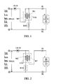
- FIG. 1 an illustration of the invention whereof the primary coil of the transformer is in series with the D.C. pulsating power supply, the essential components in this execution consist of:
- both the secondary winding WS of the transformer T101 and the optionally provided current limiting resistor R101 will be induced with normal, magnetizing currents;
- the main components include:
- the circuit represented in Fig. 4 is an adaptation of the circuit shown in Fig. 3 by the incorporation of a parallel capacitor to the existent inductor, structurally comprising:
- D.C. current will be delivered straight to the load and to excite the LC parallel loop comprising inductor L101 and capacitor C101 until it turns steadily resistive, and that run through with normal magnetizing current, as does an optionally provided current limiting resistor R101;
- D.C. current When there is power available for output from the power supply PPS101, D.C. current will pass to the load by way of the inductor L101 in serial connection;
- D.C. current When there is power available for output from the power supply PPS101, D.C. current will run to the load by way of the inductor L101 that is in parallel with the capacitor C101;
- the invention Circuit for the Generation of Electric Power Induced to Bear Opposite Polarity in the Pulsating D.C. Power Supply features simplicity in structure, low costs, novelty in design, precisely defined advantages, and for all these reasons is submitted to your highly esteemed authority for evaluation as to its patentability.
Landscapes
- Engineering & Computer Science (AREA)
- Power Engineering (AREA)
- Rectifiers (AREA)
- Generation Of Surge Voltage And Current (AREA)
- Dc-Dc Converters (AREA)
- Charge And Discharge Circuits For Batteries Or The Like (AREA)
Abstract
Description
- Circuit for the Generation of Electric Power induced to bear opposite polarity in the Pulsating Power Supply, whereby electric power of opposite polarity is generated the moment the D. C. pulsating power that is being delivered is suspended, by means of an induction device in series or in parallel with the load, or alternatively by means of an LC parallel circuit which is in series or in parallel with the load, and the power of opposite polarity thus generated is fed to the load, highlighted in substantial cut in production cost with enhanced operational reliabilities.
- In conventional arts, device of circuits for the generation of electric power of opposite polarity to make up sudden interruption of master D.C. pulsatingpower supply is prosecuted by cyclical exchange of polarities, and that involves much too complicated circuitry design associated with high costs.
- Circuit for the Generation of Electric Power induced to bear opposite polarity in the Pulsating Power Supply, whereby electric power of opposite polarity is generated the moment the D.C. pulsating power that is being delivered is suspended, by means of an induction device in series or in parallel with the load, or alternatively by means of an LC parallel circuit which is in series or in parallel with the load, and the power of opposite polarity thus generated is fed to the load, highlighted in substantial cut in production cost with enhanced operational reliabilities.
-
- Fig. 1 is an illustration of the invention circuitry with the primary coil of the transformer in series with the D.C. pulsating power supply;
- Fig. 2 is an illustration of the invention circuitry with the primary coil of the transformer in parallel with the D.C. pulsating power supply;
- Fig. 3 is an illustration of the invention circuitry using in the configuration parallel inductive elements;
- Fig. 4 is an illustration of the embodiment represented in Fig. 3 with the inductive elements further made in parallel with capacitive elements;
- Fig. 5 illustrates the invention circuitry using in the configuration serially connected inductors; and,
- Fig. 6 illustrates the invention circuitry featuring the series connection of an LC parallel loop comprising inductive and capacitive elements.
-
- The invention provides a circuit for the generation of electric power induced to bear opposite polarity in the pulsating power supply, whereby electric power of opposite polarity is generated the moment the D.C. pulsating power that is being delivered is interrupted, by means of an induction device in series or in parallel with the load, or alternatively by means of an LC parallel circuit which is in series or in parallel with the load, and the power of opposite polarity thus generated is fed to the load, highlighted in substantial cut in production costs in parallel with enhanced operational reliabilities.
- Referring to Fig. 1, an illustration of the invention whereof the primary coil of the transformer is in series with the D.C. pulsating power supply, the essential components in this execution consist of:
- D.C. pulsating power supply PPS101: yielding pulsating D.C. currents from rectification of A.C. source or D.C. source gone through linear control or switching control;
- Transformer T101: in the form of a cored or coreless transformer comprising coil windings or stacked coils which account for a primary winding WP and for a secondary winding WS respectively; with the primary winding WP made in series with the power supply, and the secondary winding WS made optionally in series with a Current Limiting Resistor R101, for paralleling across both terminals of the power supply having been made in series with a primary winding WP, the power supply being of a pulsating D.C. mode PPS101; or as pursuant to a variant execution illustrated in Fig. 2, whereof the secondary coil WS of the transformer is firstly made in parallel with the pulsating D.C. power supply PPS101, followed by allowing for serial connection of a primary coil WP, bound for the load; it is to be noted that the polarity correlation between the primary coil WP and the secondary coil WS of said transformer T101 is such that a reduction or cutoff of the causal D.C. power will bring about power of the opposite polarity on the load side;
- Load LD101: in the form of a rechargeable secondary cell or electroplating bath, or electrolytical processing electrode together with working objects, or still those necessitating the input of power of the opposite polarity in the event of power interruption or of a reduction in power supply which is necessarily pulsating D.C. power supply;
- Conduction Contacts or Plug/Socket Assembly P0: being as such composed from electromechanical components, and being optional, with one terminal connected to the charging power supply and relevant circuits on the power supply side, and the other terminal for coupling purpose going to the load side;
- Blocking Diode CR101: being structurally solid state diode in forward series with the input port of the power supply to prevent power of the opposite polarity once generated from running back to the power supply, being optional in the configuration for execution.
- The following is a description of the operation rationale of the circuits represented in both Fig. 1 and Fig. 2.
- When power is being delivered way from the power supply PPS101, which is a D.C. power supply, to the load and to the primary winding WP of the transformer T101 for excitation to a steadily resistive state at the same time, both the secondary winding WS of the transformer T101 and the optionally provided current limiting resistor R101 will be induced with normal, magnetizing currents;
- Once power due to the pulsating D.C. power supply turns down or gets cut off, power of the opposite polarity will be generated in the secondary winding WS of the transformer T101, to be delivered eventually to the load.
- In the illustration of the invention executed in a parallel inductance circuit represented in Fig. 3, the main components include:
- Pulsating D.C. power supply PPS101: generated in a controlled state by linear or switching elements, from rectified A.C. or D.C. power supply;
- Inductance L101: in the form of cored or coreless inductors wound in coil or stacked to formation, for parallel across both terminals of the power supply, to be optionally in series with a current limiting resistor R101;
- Load LD101: in the form of a rechargeable secondary cell or electroplating bath, or electrolytical processing electrode together with working objects, or still those necessitating the input of power of the opposite polarity in the event of power interruption or of a reduction in power supply which is necessarily pulsating D.C. power supply;
- Conduction Contacts or Plug/Socket Assembly P0: being as such composed from electromechanical components, and being optional, with one terminal connected to the charging power supply and relevant circuits on the power supply side, and the other terminal for coupling purpose going to the load side;
- Blocking Diode CR101: being structurally solid state diode in forward series with the input port of the power supply to prevent power of the opposite polarity once generated from running back to the power supply, being optional in the configuration for execution.
- The operation rationale of the circuit illustrated in Fig. 3 is described below:
- When power due to the pulsating D.C. power supply PPS101 is available for output, it will go straight as input to the load as well as exciting the inductor L101 till the latter is driven to a steadily resistive state; meantime generate normal, magnetizing current passing optionally the current limiting resistor R101;
- Once the pulsating D.C. power supply voltage turns down orbecomes cut off, power of the oppositepolaritywillbe induced in the inductor L101, and that delivered to the load LD101.
- The circuit represented in Fig. 4 is an adaptation of the circuit shown in Fig. 3 by the incorporation of a parallel capacitor to the existent inductor, structurally comprising:
- Pulsating D.C. Power Supply PPS101: generated in a controlled state by linear or switching elements from rectified A.C. or D.C. power source;
- Inductance L101: in the form of cored or coreless inductors wound in coil or stacked to formation, for parallel across both terminals of the power supply, to be optionally in series with a current limiting resistor R101;
- Capacitor C101: in parallel with the inductor L101 to interact with the inductor L101 and to respond resistively in accord with the frequency of the pulsating D.C. power supply;
- Load LD101: in the form of a rechargeable secondary cell or electroplating bath, or electrolytical processing electrode together with working objects, or still those necessitating the input of power of the opposite polarity in the event of power interruption or of a reduction in power supply which is necessarily pulsating D.C. power supply;
- Conduction Contacts or Plug/Socket Assembly P0: being as such composed from electromechanical components, and being optional, with one terminal connected to the charging power supply and relevant circuits on the power supply side, and the other terminal for coupling purpose going to the load side;
- Blocking Diode CR101: being structurally solid state diode in forward series with the input port of the power supply to prevent power of the opposite polarity once generated from running back to the power supply, being optional in the configuration for execution.
- What follows is a description of the operation rationale of the circuit illustrated in Fig. 4;
- When the power supply PPS101 is available for output, D.C. current will be delivered straight to the load and to excite the LC parallel loop comprising inductor L101 and capacitor C101 until it turns steadily resistive, and that run through with normal magnetizing current, as does an optionally provided current limiting resistor R101;
- Once the incoming pulsating D.C. power supply turns down or becomes cut off, power of the opposite polarity will be generated in the LC parallel loop which consists of inductor L101 and capacitor C101 for output to the load LD101.
- In the circuit comprising a serially connected inductor that is shown in Fig. 5, the essential components are described below:
- Pulsating D.C. power supply PPS101: generated in a controlled state by linear or switching elements, from rectified A. C. or from D.C. power supply;
- Inductor L101: in the form of cored or coreless inductors wound in coil or stacked to formation, for serial connection way between the output terminal of the power supply and the load LD101;
- Backflow Resistor R500: composed of resistive elements, paralleled across the positive terminal of the pulsating D.C. power supply PPS101 which is in connection with the inductor L101, and the negative terminal of the same pulsating D.C. power supply PPS101, to allow for passage of the power of opposite polarity;
- Blocking Diode CR101: being solid state diode in forward series with the input port of the power supply to prevent power of the opposite polarity once generated from running back to the power supply, being optional in the configuration for execution;
- Load LD101: in the form of a rechargeable secondary cell or electroplating bath, or electrolytical processing electrode together with working objects, or still those necessitating the input of power of the opposite polarity in the event of power interruption or of a reduction in power supply which is necessarily pulsating D.C. power supply;
- Conduction Contacts or Plug/Socket Assembly P0: being as such composed from electromechanical components, and being optional, with one terminal connected to the charging power supply and relevant circuit on the power supply side, and the other terminal for coupling purpose going to the load side.
- What follows next is a description of the circuit represented in Fig. 5;
- When there is power available for output from the power supply PPS101, D.C. current will pass to the load by way of the inductor L101 in serial connection;
- Should power supply PPS101 voltage turn down or turn off, power of the opposite polarity will be produced about the inductor L101 and delivered eventually to the load via backflow resistor R500.
- In the circuit represented in Fig. 6, an LC circuit in parallel comprising inductive and capacitive elements in series with the invention configuration, the essential components employed include:
- Pulsating D.C. power supply PPS101: generated in a controlled state by linear or switching elements from rectified A.C. or from D.C. source;
- Inductor L101: in the form of cored or coreless inductors wound in coil or stacked to formation, for serial connection way between the output terminal of the power supply and the load LD101;
- Capacitor C101: in parallel with the inductor L101 to interact with the inductor L101 and to respond resistively in accord with the frequency of the pulsating D.C. Power Supply;
- Backflow Resistor R500: composed of resistive elements, paralleled across the positive terminal of the pulsating D.C. power supply PPS101 which is in connection with the inductor L101, and the negative terminal of the same pulsating D.C. power supply PPS101, to allow for passage of the power of opposite polarity;
- Blocking Diode CR101: being solid state diode in forward series with the input port of the power supply to prevent power of the opposite polarity once generated from running back to the power supply, being optional in the configuration for execution;
- Load LD101: in the form of a rechargeable secondary cell or electroplating bath, or electrolytical processing electrode together with working objects, or still those necessitating the input of power of the opposite polarity in the event of power interruption or of a reduction in power supply which is necessarily pulsating D.C. power source;
- Conduction Contacts or Plug/Socket Assembly P0: being as such composed from electromechanical components, and being optional, with one terminal connected to the charging power supply and relevant circuit on the power supply side, and the other terminal for coupling purpose going to the load side.
- What follows next is a description of the operation rationale of the circuit illustrated in Fig. 6;
- When there is power available for output from the power supply PPS101, D.C. current will run to the load by way of the inductor L101 that is in parallel with the capacitor C101;
- Once the power supply PPS101 voltage turns down or becomes cut off, power of the opposite polarity that is developed in the inductor L101 that is in parallel with the capacitor C101 will be delivered to the Load by way of Backflow Resistor R500.
- In summation, the invention Circuit for the Generation of Electric Power Induced to Bear Opposite Polarity in the Pulsating D.C. Power Supply features simplicity in structure, low costs, novelty in design, precisely defined advantages, and for all these reasons is submitted to your highly esteemed authority for evaluation as to its patentability.
Claims (9)
- Circuit for the generation of Electric Power induced to bear opposite polarity in the Pulsating D.C. Power Supply, whereby electric power of opposite polarity is generated the moment the D.C. pulsating power that is being delivered is suspended, by means of an induction device in series or in parallel with the load, or alternatively by means of an LC parallel circuit which is in series or in parallel with the load, and the power of opposite polarity thus generated is fed to the load.
- Circuit for the generation of Electric Power induced to bear opposite polarity in the Pulsating D.C. Power Supply according to claim 1, further featuring a sub-circuit by having the primary winding of the transformer in series with the pulsating D.C. power supply, and comprising structurally essentially:D.C. pulsating power supply PPS101: yielding pulsating D.C. currents from rectification of A.C. source or D.C. source gone through linear control or switching control;Transformer T101: in the form of a cored or coreless transformer comprising coil windings or stacked coils which account for a primary winding WP and for a secondary winding WS respectively; with the primary winding WP made in series with the power supply, and the secondary winding WS made optionally in series with a Current Limiting Resistor R101, for paralleling across both terminals of the power supply having been made in series with a primary winding WP, the power supply being of a pulsating D.C. mode PPS101;or the secondary coil WS of the transformer is firstly made in parallel with the pulsating D.C. power supply PPS101, followed by allowing for serial connection of a primary coil WP, bound for the load; it is to be noted that the polarity correlation between the primary coil WP and the secondary coil WS of said transformer T101 is such that a reduction or cutoff of the causal D.C. power will bring about power of the opposite polarity on the load side;Load LD101: in the form of a rechargeable secondary cell or electroplating bath, or electrolytical processing electrode together with working objects, or still those necessitating the input of power of the opposite polarity in the event of power interruption or of a reduction in power supply which is necessarily pulsating D.C. power supply;Conduction Contacts or Plug/Socket Assembly P0: being as such composed from electromechanical components, and being optional, with one terminal connected to the charging power supply and relevant circuits on the power supply side, and the other terminal for coupling purpose going to the load side;Blocking Diode CR101: being structurally solid state diode in forward series with the input port of the power supply to prevent power of the opposite polarity once generated from running back to the power supply, being optional in the configuration for execution.
- Circuit for the Generation of Electric Power induced to bear opposite polarity in the Pulsating D.C. power supply according to claim 1, further comprising a sub-circuit by paralleling an inductor therewith, and comprising essentially:Pulsating D.C. power supply PPS101: generated in a controlled state by linear or switching elements, from rectified A.C. or D.C. power supply;Inductance L101: in the form of cored or coreless inductors wound in coil or stacked to formation, for parallel across both terminals of the power supply, to be optionally in series with a current limiting resistor R101;Load LD101: in the form of a rechargeable secondary cell or electroplating bath, or electrolytical processing electrode together with working objects, or still those necessitating the input of power of the opposite polarity in the event of power interruption or of a reduction in power supply which is necessarily pulsating D.C. power supply;Conduction Contacts or Plug/Socket Assembly P0: being as such composed from electromechanical components, and being optional, with one terminal connected to the charging power supply and relevant circuits on the power supply side, and the other terminal for coupling purpose going to the load side;Blocking Diode CR101: being structurally solid state diode in forward series with the input port of the power supply to prevent power of the opposite polarity once generated from running back to the power supply, being optional in the configuration for execution.
- Circuit for the Generation of Electric Power induced to bear opposite polarity in the Pulsating D.C. power supply according to claim 3, whereof the inductor further forms a sub-circuit by paralleling a capacitor, and comprising essentially:Pulsating D.C. Power Supply PPS101: generated in a controlled state by linear or switching elements from rectified A.C. or D.C. power source;Inductance L101: in the form of cored or coreless inductors wound in coil or stacked to formation, for parallel across both terminals of the power supply, to be optionally in series with a current limiting resistor R101;Capacitor C101: in parallel with the inductor L101 to interact with the inductor L101 and to respond resistively in accord with the frequency of the pulsating D.C. power supply;Load LD101: in the form of a rechargeable secondary cell or electroplating bath, or electrolytical processing electrode together with working objects, or still those necessitating the input of power of the opposite polarity in the event of power interruption or of a reduction in power supply which is necessarily pulsating D.C. power supply;Conduction Contacts or Plug/Socket Assembly P0: being as such composed from electromechanical components, and being optional, with one terminal connected to the charging power supply and relevant circuits on the power supply side, and the other terminal for coupling purpose going to the load side;Blocking Diode CR101: being structurally solid state diode in forward series with the input port of the power supply to prevent power of the opposite polarity once generated from running back to the power supply, being optional in the configuration for execution.
- Circuit for the Generation of Electric Power induced to bear opposite polarity in the Pulsating D.C. power supply according to claim 1, incorporating further a sub-circuit formed by serial connection of inductors, and comprising essentially:Pulsating D.C. power supply PPS101: generated in a controlled state by linear or switching elements, from rectified A.C. or from D.C. power supply;Inductor L101: in the form of cored or coreless inductors wound in coil or stacked to formation, for serial connection way between the output terminal of the power supply and the load LD101;Backflow Resistor R500: composed of resistive elements, paralleled across the positive terminal of the pulsating D.C. power supply PPS101 which is in connection with the inductor L101, and the negative terminal of the same pulsating D.C. power supply PPS101, to allow for passage of the power of opposite polarity;Blocking Diode CR101: being solid state diode in forward series with the input port of the power supply to prevent power of the opposite polarity once generated from running back to the power supply, being optional in the configuration for execution;Load LD101: in the form of a rechargeable secondary cell or electroplating bath, or electrolytical processing electrode together with working objects, or still those necessitating the input of power of the opposite polarity in the event of power interruption or of a reduction in power supply which is necessarily pulsating D.C. power supply;Conduction Contacts or Plug/Socket Assembly P0: being as such composed from electromechanical components, and being optional, with one terminal connected to the charging power supply and relevant circuit on the power supply side, and the other terminal for coupling purpose going to the load side.
- Circuit for the Generation of Electric Power induced to bear opposite polarity in the Pulsating D.C. power supply according to claim 5, further incorporating an LC parallel sub-circuit which consists of inductor and capacitor, the totality being in series with the Main circuitry, and comprising essentially:Pulsating D.C. power supply PPS101: generated in a controlled state by linear or switching elements from rectified A.C. or from D.C. source;Inductor L101: in the form of cored or coreless inductors wound in coil or stacked to formation, for serial connection way between the output terminal of the power supply and the load LD101;Capacitor C101: in parallel with the inductor L101 to interact with the inductor L101 and to respond resistively in accord with the frequency of the pulsating D.C. Power Supply;Backflow Resistor R500: composed of resistive elements, paralleled across the positive terminal of the pulsating D.C. power supply PPS101 which is in connection with the inductor L101, and the negative terminal of the same pulsating D.C. power supply PPS101, to allow for passage of the power of opposite polarity;Blocking Diode CR101: being solid state diode in forward series with the input port of the power supply to prevent power of the opposite polarity once generated from running back to the power supply, being optional in the configuration for execution;Load LD101: in the form of a rechargeable secondary cell or electroplating bath, or electrolytical processing electrode together with working objects, or still those necessitating the input of power of the opposite polarity in the event of power interruption or of a reduction in power supply which is necessarily pulsating D.C. power source; Conduction Contacts or Plug/Socket Assembly P0: being as such composed from electromechanical components, and being optional, with one terminal connected to the charging power supply and relevant circuit on the power supply side, and the other terminal for coupling purpose going to the load side.
- A circuit for the generation of electric power induced to bear opposite polarity in a pulsating D.C power supply whereby electric power of opposite polarity is generated the moment the D.C. pulsating power that is being delivered is suspended, the circuit comprising a device in series with, or parallel to, the load, whereby the power of opposite polarity thus generated is fed to the load.
- A circuit as claimed in claim 7, wherein the device is an induction device.
- A circuit as claimed in claim 7, wherein the device is an LC parallel circuit.
Priority Applications (5)
| Application Number | Priority Date | Filing Date | Title |
|---|---|---|---|
| TW90121374A TW564590B (en) | 2001-08-29 | 2001-08-29 | Reverse polarity sensing energy generation circuit of pulse power source |
| US09/940,898 US6930408B2 (en) | 2001-08-29 | 2001-08-29 | Circuit for the generation of electric power of opposite polarity in a pulsating power supply |
| CN01136244A CN1412946A (en) | 2001-08-29 | 2001-10-11 | Reverse Polarity Induction Power Generating Circuit of Pulse Power Supply |
| EP20020256491 EP1401090A1 (en) | 2001-08-29 | 2002-09-19 | Polarity inversion circuit for pulsating DC power supply |
| JP2002312737A JP4454923B2 (en) | 2001-08-29 | 2002-10-28 | Generation circuit of reverse polarity electric induction energy of pulse power supply |
Applications Claiming Priority (5)
| Application Number | Priority Date | Filing Date | Title |
|---|---|---|---|
| TW90121374A TW564590B (en) | 2001-08-29 | 2001-08-29 | Reverse polarity sensing energy generation circuit of pulse power source |
| US09/940,898 US6930408B2 (en) | 2001-08-29 | 2001-08-29 | Circuit for the generation of electric power of opposite polarity in a pulsating power supply |
| CN01136244A CN1412946A (en) | 2001-08-29 | 2001-10-11 | Reverse Polarity Induction Power Generating Circuit of Pulse Power Supply |
| EP20020256491 EP1401090A1 (en) | 2001-08-29 | 2002-09-19 | Polarity inversion circuit for pulsating DC power supply |
| JP2002312737A JP4454923B2 (en) | 2001-08-29 | 2002-10-28 | Generation circuit of reverse polarity electric induction energy of pulse power supply |
Publications (1)
| Publication Number | Publication Date |
|---|---|
| EP1401090A1 true EP1401090A1 (en) | 2004-03-24 |
Family
ID=53782986
Family Applications (1)
| Application Number | Title | Priority Date | Filing Date |
|---|---|---|---|
| EP20020256491 Ceased EP1401090A1 (en) | 2001-08-29 | 2002-09-19 | Polarity inversion circuit for pulsating DC power supply |
Country Status (5)
| Country | Link |
|---|---|
| US (1) | US6930408B2 (en) |
| EP (1) | EP1401090A1 (en) |
| JP (1) | JP4454923B2 (en) |
| CN (1) | CN1412946A (en) |
| TW (1) | TW564590B (en) |
Cited By (1)
| Publication number | Priority date | Publication date | Assignee | Title |
|---|---|---|---|---|
| NL1038640A (en) * | 2010-04-13 | 2011-10-17 | Automatic Electric Europ Special Products B V | METHOD AND DEVICE FOR AN AUDIO AMPLIFIER. |
Families Citing this family (6)
| Publication number | Priority date | Publication date | Assignee | Title |
|---|---|---|---|---|
| US20050171608A1 (en) * | 2004-01-09 | 2005-08-04 | Sdgi Holdings, Inc. | Centrally articulating spinal device and method |
| US7408324B2 (en) * | 2004-10-27 | 2008-08-05 | Access Business Group International Llc | Implement rack and system for energizing implements |
| US8339096B2 (en) * | 2006-11-20 | 2012-12-25 | Semiconductor Energy Laboratory Co., Ltd. | Wireless power receiving device |
| US8725383B2 (en) * | 2008-07-16 | 2014-05-13 | Tai-Her Yang | Integrally combined operative control unit having multiple operative devices of different types |
| TWI407111B (en) * | 2010-11-18 | 2013-09-01 | Univ Ishou | Current direction detecting module |
| DE102013215993A1 (en) * | 2013-08-13 | 2015-03-12 | Robert Bosch Gmbh | Method and device for operating an inductive element |
Citations (3)
| Publication number | Priority date | Publication date | Assignee | Title |
|---|---|---|---|---|
| US4691158A (en) * | 1983-12-07 | 1987-09-01 | Kabushiki Kaisha Meidensha | Method of operating a secondary battery to recondition the battery |
| EP1026769A2 (en) * | 1999-02-03 | 2000-08-09 | Nokia Mobile Phones Ltd. | Device for reactivation of an electric battery |
| US6278260B1 (en) * | 1999-12-08 | 2001-08-21 | Tai-Her Yang | Charging device which monitors charging by detecting a temperature of the battery and which includes compensation for increases or decreases in ambient temperature |
Family Cites Families (3)
| Publication number | Priority date | Publication date | Assignee | Title |
|---|---|---|---|---|
| US5180964A (en) * | 1990-03-28 | 1993-01-19 | Ewing Gerald D | Zero-voltage switched FM-PWM converter |
| DE19623828A1 (en) * | 1996-06-14 | 1998-01-02 | Siemens Ag | Circuit arrangement for voltage reversal |
| US5682067A (en) * | 1996-06-21 | 1997-10-28 | Sierra Applied Sciences, Inc. | Circuit for reversing polarity on electrodes |
-
2001
- 2001-08-29 US US09/940,898 patent/US6930408B2/en not_active Expired - Fee Related
- 2001-08-29 TW TW90121374A patent/TW564590B/en not_active IP Right Cessation
- 2001-10-11 CN CN01136244A patent/CN1412946A/en active Pending
-
2002
- 2002-09-19 EP EP20020256491 patent/EP1401090A1/en not_active Ceased
- 2002-10-28 JP JP2002312737A patent/JP4454923B2/en not_active Expired - Fee Related
Patent Citations (3)
| Publication number | Priority date | Publication date | Assignee | Title |
|---|---|---|---|---|
| US4691158A (en) * | 1983-12-07 | 1987-09-01 | Kabushiki Kaisha Meidensha | Method of operating a secondary battery to recondition the battery |
| EP1026769A2 (en) * | 1999-02-03 | 2000-08-09 | Nokia Mobile Phones Ltd. | Device for reactivation of an electric battery |
| US6278260B1 (en) * | 1999-12-08 | 2001-08-21 | Tai-Her Yang | Charging device which monitors charging by detecting a temperature of the battery and which includes compensation for increases or decreases in ambient temperature |
Non-Patent Citations (2)
| Title |
|---|
| FUJII M ET AL: "Resonant DC/DC converter with class D inverter and class E synchronous rectifier using thinned-out method", TELECOMMUNICATIONS ENERGY CONFERENCE, 1995. INTELEC '95., 17TH INTERNATIONAL THE HAGUE, NETHERLANDS 29 OCT.-1 NOV. 1995, NEW YORK, NY, USA,IEEE, US, 29 October 1995 (1995-10-29), pages 496 - 501, XP010161282, ISBN: 0-7803-2750-0 * |
| KAZIMIERCZUK M K ET AL: "CLASS D VOLTAGE-SWITCHING INVERTER WITH TAPPED RESONANT INDUCTOR", IEE PROCEEDINGS B. ELECTRICAL POWER APPLICATIONS, INSTITUTION OF ELECTRICAL ENGINEERS. STEVENAGE, GB, vol. 140, no. 3 PART B, 1 May 1993 (1993-05-01), pages 177 - 185, XP000304271 * |
Cited By (1)
| Publication number | Priority date | Publication date | Assignee | Title |
|---|---|---|---|---|
| NL1038640A (en) * | 2010-04-13 | 2011-10-17 | Automatic Electric Europ Special Products B V | METHOD AND DEVICE FOR AN AUDIO AMPLIFIER. |
Also Published As
| Publication number | Publication date |
|---|---|
| JP4454923B2 (en) | 2010-04-21 |
| JP2004147476A (en) | 2004-05-20 |
| CN1412946A (en) | 2003-04-23 |
| US20030042797A1 (en) | 2003-03-06 |
| US6930408B2 (en) | 2005-08-16 |
| TW564590B (en) | 2003-12-01 |
Similar Documents
| Publication | Publication Date | Title |
|---|---|---|
| RU2530010C2 (en) | Non-contact power source equipment | |
| JP3416863B2 (en) | Power supply | |
| JP3906708B2 (en) | Non-contact power transmission device | |
| CN104218684B (en) | Inductive power transmission device and system | |
| JPS63257458A (en) | Single-ended cut-off DC-DC converter | |
| US9570225B2 (en) | Magnetoelectric device capable of storing usable electrical energy | |
| JP2018121390A (en) | Switching power supply | |
| US20030042797A1 (en) | Circuit for the generation of electric power induced to bear opposite polarity in the pulsating power supply | |
| JP2021164391A (en) | Contactless power reception device | |
| JP6245372B2 (en) | Power conversion apparatus and wireless power transmission system | |
| US6657402B2 (en) | Portable device with reduced power dissipation | |
| JP6945429B2 (en) | Insulated switching power supply | |
| JP3478114B2 (en) | Secondary side power receiving circuit of non-contact power supply equipment | |
| JP4631870B2 (en) | Secondary power receiving circuit for contactless power supply equipment | |
| KR20200097722A (en) | Isolated switching power supply | |
| JP6930890B2 (en) | Insulated switching power supply | |
| JP4470478B2 (en) | Power supply | |
| JP5550137B2 (en) | Contactless power supply equipment | |
| CN120222815A (en) | A dual-voltage-stabilized power supply output device and a dual piezoelectric ceramic stacking structure | |
| EP3054592A1 (en) | Magnetoelectric device capable of storing usable electrical energy | |
| JP2021164394A (en) | Contactless power reception device | |
| CN121124378A (en) | Energy transmission devices for separately excited motors, separately excited motors and drive units | |
| JPS6037039Y2 (en) | rectifier circuit | |
| JP4176090B2 (en) | Voltage conversion circuit and power supply device | |
| JPH0746841A (en) | DC power supply |
Legal Events
| Date | Code | Title | Description |
|---|---|---|---|
| PUAI | Public reference made under article 153(3) epc to a published international application that has entered the european phase |
Free format text: ORIGINAL CODE: 0009012 |
|
| AK | Designated contracting states |
Kind code of ref document: A1 Designated state(s): AT BE BG CH CY CZ DE DK EE ES FI FR GB GR IE IT LI LU MC NL PT SE SK TR |
|
| AX | Request for extension of the european patent |
Extension state: AL LT LV MK RO SI |
|
| 17P | Request for examination filed |
Effective date: 20040923 |
|
| AKX | Designation fees paid |
Designated state(s): AT BE BG CH CY CZ DE DK EE ES FI FR GB GR IE IT LI LU MC NL PT SE SK TR |
|
| 17Q | First examination report despatched |
Effective date: 20060831 |
|
| APBK | Appeal reference recorded |
Free format text: ORIGINAL CODE: EPIDOSNREFNE |
|
| APBN | Date of receipt of notice of appeal recorded |
Free format text: ORIGINAL CODE: EPIDOSNNOA2E |
|
| APBR | Date of receipt of statement of grounds of appeal recorded |
Free format text: ORIGINAL CODE: EPIDOSNNOA3E |
|
| APAF | Appeal reference modified |
Free format text: ORIGINAL CODE: EPIDOSCREFNE |
|
| APBT | Appeal procedure closed |
Free format text: ORIGINAL CODE: EPIDOSNNOA9E |
|
| STAA | Information on the status of an ep patent application or granted ep patent |
Free format text: STATUS: THE APPLICATION HAS BEEN REFUSED |
|
| 18R | Application refused |
Effective date: 20150120 |