EP1401043A2 - Flow disruptor enhanced fuel cell - Google Patents
Flow disruptor enhanced fuel cell Download PDFInfo
- Publication number
- EP1401043A2 EP1401043A2 EP03255776A EP03255776A EP1401043A2 EP 1401043 A2 EP1401043 A2 EP 1401043A2 EP 03255776 A EP03255776 A EP 03255776A EP 03255776 A EP03255776 A EP 03255776A EP 1401043 A2 EP1401043 A2 EP 1401043A2
- Authority
- EP
- European Patent Office
- Prior art keywords
- fuel cell
- fluid
- flow
- cell assembly
- disruptors
- Prior art date
- Legal status (The legal status is an assumption and is not a legal conclusion. Google has not performed a legal analysis and makes no representation as to the accuracy of the status listed.)
- Withdrawn
Links
Images


Classifications
-
- H—ELECTRICITY
- H01—ELECTRIC ELEMENTS
- H01M—PROCESSES OR MEANS, e.g. BATTERIES, FOR THE DIRECT CONVERSION OF CHEMICAL ENERGY INTO ELECTRICAL ENERGY
- H01M8/00—Fuel cells; Manufacture thereof
- H01M8/04—Auxiliary arrangements, e.g. for control of pressure or for circulation of fluids
- H01M8/04007—Auxiliary arrangements, e.g. for control of pressure or for circulation of fluids related to heat exchange
-
- H—ELECTRICITY
- H01—ELECTRIC ELEMENTS
- H01M—PROCESSES OR MEANS, e.g. BATTERIES, FOR THE DIRECT CONVERSION OF CHEMICAL ENERGY INTO ELECTRICAL ENERGY
- H01M8/00—Fuel cells; Manufacture thereof
- H01M8/04—Auxiliary arrangements, e.g. for control of pressure or for circulation of fluids
-
- H—ELECTRICITY
- H01—ELECTRIC ELEMENTS
- H01M—PROCESSES OR MEANS, e.g. BATTERIES, FOR THE DIRECT CONVERSION OF CHEMICAL ENERGY INTO ELECTRICAL ENERGY
- H01M8/00—Fuel cells; Manufacture thereof
- H01M8/02—Details
- H01M8/0202—Collectors; Separators, e.g. bipolar separators; Interconnectors
- H01M8/0258—Collectors; Separators, e.g. bipolar separators; Interconnectors characterised by the configuration of channels, e.g. by the flow field of the reactant or coolant
-
- H—ELECTRICITY
- H01—ELECTRIC ELEMENTS
- H01M—PROCESSES OR MEANS, e.g. BATTERIES, FOR THE DIRECT CONVERSION OF CHEMICAL ENERGY INTO ELECTRICAL ENERGY
- H01M8/00—Fuel cells; Manufacture thereof
- H01M8/02—Details
- H01M8/0202—Collectors; Separators, e.g. bipolar separators; Interconnectors
- H01M8/0267—Collectors; Separators, e.g. bipolar separators; Interconnectors having heating or cooling means, e.g. heaters or coolant flow channels
-
- H—ELECTRICITY
- H01—ELECTRIC ELEMENTS
- H01M—PROCESSES OR MEANS, e.g. BATTERIES, FOR THE DIRECT CONVERSION OF CHEMICAL ENERGY INTO ELECTRICAL ENERGY
- H01M8/00—Fuel cells; Manufacture thereof
- H01M8/10—Fuel cells with solid electrolytes
-
- H—ELECTRICITY
- H01—ELECTRIC ELEMENTS
- H01M—PROCESSES OR MEANS, e.g. BATTERIES, FOR THE DIRECT CONVERSION OF CHEMICAL ENERGY INTO ELECTRICAL ENERGY
- H01M8/00—Fuel cells; Manufacture thereof
- H01M8/10—Fuel cells with solid electrolytes
- H01M8/1007—Fuel cells with solid electrolytes with both reactants being gaseous or vaporised
-
- H—ELECTRICITY
- H01—ELECTRIC ELEMENTS
- H01M—PROCESSES OR MEANS, e.g. BATTERIES, FOR THE DIRECT CONVERSION OF CHEMICAL ENERGY INTO ELECTRICAL ENERGY
- H01M8/00—Fuel cells; Manufacture thereof
- H01M8/10—Fuel cells with solid electrolytes
- H01M8/12—Fuel cells with solid electrolytes operating at high temperature, e.g. with stabilised ZrO2 electrolyte
- H01M8/1231—Fuel cells with solid electrolytes operating at high temperature, e.g. with stabilised ZrO2 electrolyte with both reactants being gaseous or vaporised
-
- H—ELECTRICITY
- H01—ELECTRIC ELEMENTS
- H01M—PROCESSES OR MEANS, e.g. BATTERIES, FOR THE DIRECT CONVERSION OF CHEMICAL ENERGY INTO ELECTRICAL ENERGY
- H01M8/00—Fuel cells; Manufacture thereof
- H01M8/24—Grouping of fuel cells, e.g. stacking of fuel cells
- H01M8/241—Grouping of fuel cells, e.g. stacking of fuel cells with solid or matrix-supported electrolytes
- H01M8/2425—High-temperature cells with solid electrolytes
- H01M8/243—Grouping of unit cells of tubular or cylindrical configuration
-
- H—ELECTRICITY
- H01—ELECTRIC ELEMENTS
- H01M—PROCESSES OR MEANS, e.g. BATTERIES, FOR THE DIRECT CONVERSION OF CHEMICAL ENERGY INTO ELECTRICAL ENERGY
- H01M8/00—Fuel cells; Manufacture thereof
- H01M8/24—Grouping of fuel cells, e.g. stacking of fuel cells
- H01M8/241—Grouping of fuel cells, e.g. stacking of fuel cells with solid or matrix-supported electrolytes
- H01M8/2425—High-temperature cells with solid electrolytes
- H01M8/2432—Grouping of unit cells of planar configuration
-
- Y—GENERAL TAGGING OF NEW TECHNOLOGICAL DEVELOPMENTS; GENERAL TAGGING OF CROSS-SECTIONAL TECHNOLOGIES SPANNING OVER SEVERAL SECTIONS OF THE IPC; TECHNICAL SUBJECTS COVERED BY FORMER USPC CROSS-REFERENCE ART COLLECTIONS [XRACs] AND DIGESTS
- Y02—TECHNOLOGIES OR APPLICATIONS FOR MITIGATION OR ADAPTATION AGAINST CLIMATE CHANGE
- Y02E—REDUCTION OF GREENHOUSE GAS [GHG] EMISSIONS, RELATED TO ENERGY GENERATION, TRANSMISSION OR DISTRIBUTION
- Y02E60/00—Enabling technologies; Technologies with a potential or indirect contribution to GHG emissions mitigation
- Y02E60/30—Hydrogen technology
- Y02E60/50—Fuel cells
Definitions
- the present invention relates generally to power generation equipment such as fuel cells, and particularly to thermal management of fuel cells, for example, solid oxide fuel cells.
- a fuel cell is an energy conversion device that produces electricity by electrochemically combining a fuel and an oxidant across an ionic conducting layer.
- a high temperature fuel cell bundle for example, a solid oxide fuel cell bundle is typically constructed from flat single members having a planar configuration.
- the planar fuel cells can be of counter-flow, cross-flow and parallel flow varieties.
- the planar fuel cell typically comprises tri-layer anode/electrolyte/cathode components that conduct current from cell to cell and provide channels for gas flow into a cubic structure or stack.
- Fuel cells such as solid oxide fuel cells, have demonstrated potential for high efficiency and low pollution in power generation.
- problems associated with thermal management persist, particularly in regulating the temperature gradient of the fuel cell components.
- Thermal energy generated in the fuel cell from the reaction of the fuel and the oxidant needs to be removed or used internally in order to maintain the operating temperature in the fuel cell.
- Cooling channels in the fuel cells typically use an oxidant, such as air, to aid in the transfer or removal of waste heat from the fuel cell to the oxidant, so as to maintain a stack temperature at or below prescribed limits and maintain a predetermined thermal gradient.
- a temperature difference between a fuel cell assembly and a fluid, such as the oxidant is a function of heat transfer characteristics of the fluid flowing through the fluid flow channel and a heat flux generated in the fuel cell assembly.
- One embodiment of the present invention provides a fuel cell assembly comprising at least one fuel cell.
- the fuel cell comprises an anode, a cathode, and a electrolyte interposed therebetween; at least one fluid flow channel disposed within the fuel cell for delivering a fluid to the fuel cell and at least one array of flow disruptors in contact with at least one of the anode, the cathode and the electrolyte.
- the flow disruptors protrude into the fluid flow channel so as to disrupt a fluid flow and enhance a heat transfer rate between the fluid and the fuel cell assembly when the fluid is introduced into the fluid flow channel.
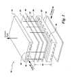
- the present invention provides a fuel cell assembly 10, for example a solid oxide fuel cell (hereinafter "SOFC") assembly, which typically comprises an array, bundle or stack of fuel cells comprising at least one fuel cell 50 (see Figure 1).
- SOFC solid oxide fuel cell
- Each fuel cell 50 is a repeat fuel cell unit 50 capable of being stacked together either in series or in parallel or both to build a fuel cell stack system or architecture that is capable of producing an electrical energy output.
- the fuel cell 50 can be any type of fuel cells, which require flow channels, such as solid oxide fuel cells, proton exchange membrane fuel cells, molten carbonate fuel cells, phosphoric acid fuel cells, alkaline fuel cells, direct methanol fuel cells, regenerative fuel cells, zinc air fuel cells, and protonic ceramic fuel cells.
- flow channels such as solid oxide fuel cells, proton exchange membrane fuel cells, molten carbonate fuel cells, phosphoric acid fuel cells, alkaline fuel cells, direct methanol fuel cells, regenerative fuel cells, zinc air fuel cells, and protonic ceramic fuel cells.
- the exemplary fuel cell 50 for example, the solid oxide fuel cell is illustrated in Figure 1.
- An oxidant 38 for example air
- Oxygen ions (O 2- ) generated at the cathode 30 are transported across an electrolyte 40 interposed between an anode 20 and the cathode 30.
- a fuel 34 for example natural gas, is fed to the anode 20.
- the fuel 34 at the anode 20 reacts with oxygen ions (O 2- ) being migrated to the anode 20 across the electrolyte 40.
- the oxygen ions (O 2- ) are de-ionized to release electrons to an external electric circuit (not shown).
- the electron flow thus produces direct current electricity across the external electric circuit (not shown).
- the electricity generation process produces certain exhaust gases and generates waste heat.
- the anode 20 typically provides reaction sites for the electrochemical oxidation of a gas fuel introduced into the fuel cell 50. Accordingly, it is desirable that the anode 20 be passive against a fuel-reducing environment and have adequate electronic conductivity. In addition, it is desirable that the anode 20 promotes catalytic activity for fuel gas reaction at the fuel cell 50 operating conditions and has sufficient porosity to allow gas transport to the reaction sites.
- the materials suitable for the anode 20 having aforesaid properties include, but are not limited to, metallic nickel, nickel alloy, silver, copper, cobalt, ruthenium, nickel-yttria-stabilized zirconia cermets (Ni-YSZ cermets), copper-yttria-stabilized zirconia cermets (Cu-YSZ cermets), Ni-Ceria cermets, Ceramics or combinations thereof.
- the cathode 30 typically provides reaction sites for the electrochemical reduction of the oxidant. Accordingly, it is desirable that the cathode 30 be passive against an oxidizing environment and has sufficient electronic conductivity. In addition, it is desirable that the cathode 30 promotes catalytic activity for the oxidant gas reaction at the fuel cell 50 operating conditions and has sufficient porosity to allow gas transport to the reaction sites.
- the materials suitable for the cathode 30 having aforesaid properties include, but are not limited to, perovskite doped lanthanum manganate (LaMnO 3 ), strontium-doped LaMnO 4 (SLM), tin doped Indium Oxide (In 2 O 3 ), strontium-doped PrMnO 3 , LaFeO 3 -LaCoO 3 RuO 2 -Yttria-stabilized zirconia (YSZ), lanthanum cobaltite, and combinations thereof.
- LaMnO 3 perovskite doped lanthanum manganate
- SLM strontium-doped LaMnO 4
- tin doped Indium Oxide In 2 O 3
- strontium-doped PrMnO 3 LaFeO 3 -LaCoO 3 RuO 2 -Yttria-stabilized zirconia (YSZ), lanthanum cobaltite, and combinations thereof.
- the anode 20 and the cathode 30 typically have a surface area sufficient to support electrochemical reactions.
- the materials used for the anode 20 and the cathode 30 are thermally stable between the typical minimum and maximum operating temperature of the fuel cell assembly 10, for example between about 600°C to about 1300°C.
- the electrolyte 40 is typically disposed between the anode 20 and the cathode 30 as shown in exemplary exploded isometric view of the fuel cell 50 in Figure 1.
- the electrolyte 40 serves to transport ions, such as oxygen ions (O 2- ), between the cathode 30 and the anode 20.
- the electrolyte 40 separates the fuel 34 from the oxidant 38 in the fuel cell 50. Accordingly, it is desirable that the electrolyte 40 be passive against both the fuel reducing and the oxidizing environments and impermeable to the reacting gases. In addition, it is desirable that the electrolyte 40 be sufficiently conductive at the operating conditions of the fuel cell 50.
- the materials suitable for the electrolyte 40 having aforesaid properties include, but are not limited to, zirconium oxide, yttria stabilized zirconia (YSZ), doped ceria, cerium oxide (CeO 2 ), bismuth sesquioxide, pyrochlore oxides, doped zirconates, perovskite oxide materials and combinations thereof.
- An interconnect 24 typically electrically connects the anode 20 of one repeatable fuel cell 50 unit to the cathode 30 of an adjacent fuel cell 50 unit (see Figure 1).
- the interconnect 24 should provide uniform current distribution and be impermeable to fuel and oxidant gases. It is desirable that the interconnect 24 be passive against both the fuel reducing and the oxidizing environments and be sufficiently conductive to support electron flow at a variety of temperatures of the fuel cell 50.
- the materials suitable for the interconnect 24 having aforesaid properties include, but are not limited to, chromium based ferritic stainless steel, cobaltite, ceramic, lanthanum chromate (LaCrO 3 ), cobalt dichromate (CoCr 2 O 4 ), Inconel 600, Inconel 601, Hastelloy X, Hastelloy-230, Ducrolloy, Kovar, Ebrite and combinations thereof.
- the fuel cell 50 such as the solid oxide fuel cell 50 comprises the anode 20, the cathode 30 and the electrolyte 40 interposed therebetween. At least one fluid flow channel 95 is disposed within the fuel cell 50.
- at least one array of flow disruptors 25 is coupled to least one of the anode 20, the cathode 30 and the electrolyte 40.
- the flow disruptors 250, 255 extend from the electrolyte 40 through a surface of at least one of the anode 20 and the cathode 30.
- the fluid flow channel 95 typically comprises at least one oxidant flow channel 28 and at least one fuel flow channel 36 disposed within the fuel cell 50 (see Figure 1).
- the array of flow disruptors 25 further include a second array of flow disruptors 32.
- the flow disruptors 25,32 extend from the electrolyte 40 into at least one of the cathode 30 and the anode 20.
- the flow disruptors 25,32 typically comprise, but are not limited to, discrete pins, trip strips and baffle turbulators.
- these flow disruptors 25,32 protrude into at least one of the oxidant flow channel 28 and the fuel flow channel 36 to disrupt a fluid flow, for example, the oxidant flow 38, the fuel flow 34 or both.
- the oxidant flow 38 inside the oxidant flow channel 28 as well as the fuel flow 34 inside the fuel flow channel 36 in fuel cell 50 illustrated in Figure 1 is typically either laminar or transitional having Reynolds number characteristics lower than critical Reynolds number.
- the flow disruptors 25 typically create an unsteady wake 27 behind each flow disruptor 25. The unsteady wake 27 is created due to separation of a boundary layer between the fluid flow, such as oxidant flow 38, and the flow disruptor 25.
- the term "unsteady wake” refers to a turbulence created in the fluid flow path across the fluid flow channel 95 such as the oxidant flow channel 28 in Figure 1.
- Creating turbulence in the fluid flow path across the fluid flow channel 95, for example the oxidant flow channel 28, enhances the Nusselt number of a fluid flow for example an oxidant flow 38 across the fluid flow channel 95 such as oxidant flow channel 28.
- Enhancing the Nusselt number of the fluid flow across the fluid flow channel 95 improves the convective heat transfer characteristics significantly beyond the baseline laminar convective heat transfer characteristics between the fluid and the fuel cell 50. Enhanced heat transfer characteristics increase the ability to remove heat from the fuel cell 50 more efficiently and more effectively.
- a temperature difference between a fuel cell 50 and a fluid, such as the oxidant 38, is a function of heat transfer characteristics of the fluid flowing through the fluid flow channel 95 and a heat flux generated in the fuel cell 50 in Figure 1.
- Such enhanced heat transfer characteristics addresses improved cooling requirements of the fuel cell assembly 10 comprising a plurality of fuel cell 50.
- Enhancing heat transfer characteristics of the fuel cell 50 also ensures maintaining a predetermined uniform thermal gradient and temperature level globally across the entire fuel cell 50. Maintaining the predetermined uniform thermal gradient across the fuel cell 50 aids in avoiding generation of potential thermal hot spots in different locations of the fuel cell assembly 10. In the fuel cell assembly 10 in Figure 1, thermal hot spots degenerate thermal performance and life of the fuel cell assembly 10 substantially.
- heat transfer characteristics of the fuel cell assembly 10 significantly improve thermal performance and life of the fuel cell assembly 10 compared to a fuel cell assembly with baseline laminar convective heat transfer characteristics. Additionally, the fuel cell assembly with baseline laminar convective heat transfer characteristics typically does not address additional cooling requirement of the fuel cell assembly 10, unless fluid flow, such as the oxidant flow 38 through the oxidant flow channel 28 in Figure 1 is substantially increased.
- the flow disruptors 25,32 enhance thermal performance and life of the fuel cell assembly 10 without increasing the fluid flow, such as oxidant flow 38, flowing through the oxidant flow channel 28.
- the array of flow disruptors 25,32 has a width 52 in the range between about 0.020 inches to about 0.25 inches (see Figure 3 and Figure 5).
- the flow disruptors 25,32 have a substantially constant cross-sectional area that typically ensure uniform heat transfer characteristics throughout the array of flow disruptors 25,32.
- the flow disruptors 25,32 have a cross-sectional shape typically comprising, but not limited to, square, rectangular, circular, elliptical, annular and irregular shapes. It will be appreciated that the choice of flow disruptor 25,32 width 52, cross sectional shape and cross sectional area are left to the artisan so as to provide improved structural stability and strength to the fuel cell 50 layers in Figure 1.
- the flow disruptors 25,32 typically provide increased surface area at an interface of at least one of the anode 20, electrolyte 40 and cathode 30 so as to enhance electrochemical reaction rate across layers of the anode 20, the cathode 30 and the electrolyte 40.
- the array of flow disruptors 25,32 typically comprise in-line, staggered, uniformly spaced, and irregularly spaced arrangements.
- Figure 4 represents an exemplary in-line arrangement of the array of flow disruptors 25,32.
- a distance 51 between subsequent flow disruptors 25,32 is irregular.
- a distance 53 between subsequent flow disruptors 25,32 is uniform.
- Figure 6 shows a staggered arrangement of the array of flow disruptors 25,32. It will be appreciated that an arrangement and spacing of the flow disruptors 25,32 may vary depending upon a desired application.
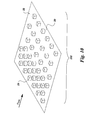
- One exemplary embodiment in Figure 9 shows an arrangement of flow disruptors 25,32 with a patterned array 251, distributed evenly around the periphery of a surface of at least one of the anode 20, the cathode 30 and the electrolyte 40.
- Another exemplary embodiment in Figure 10 shows an arrangement of flow disruptors 25,32 with a patterned array 252 stretched unevenly throughout the surface of at least one of the anode 20, the cathode 30 and the electrolyte 40.
- Arrangement and spacing of flow disruptors 25,32 also control a typical region of interaction or re-circulation 253 for the unsteady wakes 27 in Figure 8.
- these unsteady wakes are generated due to a boundary layer separation of the fluid from each flow disruptor 25 when each flow disruptor 25 is exposed to a stream of either oxidant flow 38 or fuel flow 34.
- Controlling the typical region of interaction or re-circulation 253 for the unsteady wakes 27 tailors flow distribution profile and maintains thermal-hydrodynamic stability in desired locations across the fluid flow path of the fluid flow channel 95 of the fuel cell 50 in Figure 1.
- arrangement, spacing and cross sectional shape of flow disruptors 25,32 are typically chosen by an artisan skilled in the art in such a fashion as to tailor thermal gradient across the exemplary fuel cell assembly 10 illustrated in Figure 1, at desired locations. Tailored thermal gradient in desired locations across the fuel cell assembly 10 ensures maintaining desired thermal potential across the fuel cell assembly 10.
- the flow disruptors 25,32 be passive against both the fuel reducing and the oxidizing environments and be impermeable to the fuel and oxidant gases. In addition, it is desirable that the flow disruptors withstand heat flux across the fuel cell 50.
- the flow disruptors 25,32 comprise a ceramic material. In another embodiment, the flow disruptors comprise a material as one of the anode 20, the cathode 30 and the electrolyte 40.
- the materials suitable for the flow disruptors 25,32 having the aforesaid properties include, but are not limited to, metallic nickel, silver, copper, cobalt, ruthenium, nickel-yttria-stabilized zirconia cermets (Ni-YSZ cermets), copper-yttria-stabilized zirconia cermets (Cu-YSZ cermets), Ni-Ceria cermets, perovskite doped lanthanum manganate (LaMnO 3 ), strontium-doped LaMnO 4 (SLM), tin doped Indium Oxide (In 2 O 3 ), strontium-doped PrMnO 3 , LaFeO 3 -LaCoO 3 RuO 2 -Yttria-stabilized zirconia (YSZ), lanthanum cobaltite, zirconium oxide, yttria stabilized zirconia (YSZ), doped ceria, cerium oxide (Ce
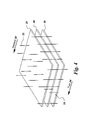
- Figure 7 represents an exemplary arrangement of the flow disruptors 25 for a tubular fuel cell.
Landscapes
- Life Sciences & Earth Sciences (AREA)
- Engineering & Computer Science (AREA)
- Manufacturing & Machinery (AREA)
- Sustainable Development (AREA)
- Sustainable Energy (AREA)
- Chemical & Material Sciences (AREA)
- Chemical Kinetics & Catalysis (AREA)
- Electrochemistry (AREA)
- General Chemical & Material Sciences (AREA)
- Fuel Cell (AREA)
Abstract
Description
Claims (10)
- A fuel cell assembly (10) comprising:at least one fuel cell (50) comprising an anode (20), a cathode (30), and an electrolyte (40) interposed therebetween;at least one fluid flow channel (95) disposed within said at least one fuel cell (50) for delivering a fluid to said fuel cell (50); andat least one array of flow disruptors (25) in contact with at least one of said anode (20), said cathode (30) and said electrolyte (40), said flow disruptors (25) protruding into said fluid flow channel (95) so as to disrupt a flow of said fluid and enhance a heat transfer rate between said fluid and said fuel cell assembly (10) when said fluid is introduced into said fluid flow channel (95).
- The fuel cell assembly (10) in accordance with Claim 1, wherein said array of flow disruptors (25) further comprises a second array of flow disruptors(32) extending from said electrolyte (40) into at least one of said cathode (30) and said anode (20).
- The fuel cell assembly (10) in accordance with Claim 1 or 2, wherein said fuel cell (50) is typically selected from the group consisting of solid oxide fuel cells, proton exchange membrane fuel cells, molten carbonate fuel cells, phosphoric acid fuel cells, alkaline fuel cells, direct methanol fuel cells, regenerative fuel cells, zinc air fuel cells, and protonic ceramic fuel cells.
- The fuel cell assembly (10) in accordance with Claim 1, 2 or 3, wherein said fuel cell (50) comprises at least one fuel cell (50) having planar configuration.
- The fuel cell assembly (10) in accordance with Claim 1, 2 or 3, wherein said fuel cell (50) comprises at least one fuel cell (50) having tubular configuration
- The fuel cell assembly (10) comprising:at least one fuel cell (50) comprising an anode (20), a cathode (30), and an electrolyte (40) interposed therebetween;at least one fluid flow channel (95) disposed within said at least one fuel cell (50) for delivering a fluid to said fuel cell (50); andat least one array of flow disruptors (25,32) extending from said electrolyte (40) through at least one of said anode (20), said cathode (30) and said electrolyte (40) further including a second array of flow disruptors (25,32) extending from said electrolyte (40) into at least one of said cathode (30) and said anode (20), said flow disruptors (25,32) protruding into said fluid flow channel (95) so as to disrupt a flow of said fluid and enhance a heat transfer rate between said fluid and said fuel cell assembly (10) when said fluid is introduced into said fluid flow channel (95).
- The fuel cell assembly (10) in accordance with Claim 6, wherein said flow disruptors (25,32) are typically selected from the group consisting of discrete pins, trip strips and baffle turbulators.
- The fuel cell assembly (10) in accordance with Claim 6, or 7 wherein said flow disruptors (25,32) have a substantially constant cross sectional area.
- The fuel cell assembly (10) in accordance with Claim 6, 7 or 8, wherein said flow disruptors (25,32) have a cross-sectional shape selected from the group consisting of square, rectangular, circular, elliptical, annular and irregular shapes.
- The fuel cell assembly (10) in accordance with any one of Claims 6 to 9, wherein said flow disruptors (25,32) have a width in the range between about 0.020 inches to about 0.25 inches.
Applications Claiming Priority (2)
| Application Number | Priority Date | Filing Date | Title |
|---|---|---|---|
| US10/246,066 US7090942B2 (en) | 2002-09-18 | 2002-09-18 | Flow disruptor enhanced fuel cell |
| US246066 | 2002-09-18 |
Publications (2)
| Publication Number | Publication Date |
|---|---|
| EP1401043A2 true EP1401043A2 (en) | 2004-03-24 |
| EP1401043A3 EP1401043A3 (en) | 2007-02-14 |
Family
ID=31946415
Family Applications (1)
| Application Number | Title | Priority Date | Filing Date |
|---|---|---|---|
| EP03255776A Withdrawn EP1401043A3 (en) | 2002-09-18 | 2003-09-16 | Flow disruptor enhanced fuel cell |
Country Status (8)
| Country | Link |
|---|---|
| US (1) | US7090942B2 (en) |
| EP (1) | EP1401043A3 (en) |
| JP (1) | JP5057634B2 (en) |
| KR (1) | KR20040025602A (en) |
| CN (1) | CN1495949A (en) |
| AU (1) | AU2003231695A1 (en) |
| CA (1) | CA2439718A1 (en) |
| SG (1) | SG112891A1 (en) |
Cited By (3)
| Publication number | Priority date | Publication date | Assignee | Title |
|---|---|---|---|---|
| DE102016202080A1 (en) * | 2016-02-11 | 2017-08-17 | Robert Bosch Gmbh | fuel cell device |
| WO2018114505A1 (en) * | 2016-12-22 | 2018-06-28 | Robert Bosch Gmbh | Process for producing a fuel and/or electrolysis cell and fuel and/or electrolysis cell |
| EP4084161A1 (en) * | 2021-04-26 | 2022-11-02 | General Electric Company | High performance fuel cells |
Families Citing this family (11)
| Publication number | Priority date | Publication date | Assignee | Title |
|---|---|---|---|---|
| US7261124B2 (en) * | 2004-09-10 | 2007-08-28 | General Motors Corporation | Bipolar plate channel structure with knobs for the improvement of water management in particular on the cathode side of a fuel cell |
| JP5252362B2 (en) * | 2005-12-28 | 2013-07-31 | 独立行政法人産業技術総合研究所 | Ceramic electrode |
| JP2008274929A (en) * | 2007-03-30 | 2008-11-13 | Sanyo Electric Co Ltd | Fluid transfer device and fuel cell having the same |
| US10161692B2 (en) * | 2007-07-25 | 2018-12-25 | Doosan Fuel Cell America, Inc. | Tailored heat transfer characteristic of fuel cell coolers |
| KR101074493B1 (en) | 2009-04-09 | 2011-10-18 | 인제대학교 산학협력단 | PEMFC having a pin type flow channel |
| US8697301B2 (en) * | 2010-01-29 | 2014-04-15 | Formfactor, Inc. | Fuel cell using carbon nanotubes |
| KR101220598B1 (en) * | 2010-12-28 | 2013-01-10 | 주식회사 포스코 | Solid oxide fuel cell and method for manufacturing the same |
| DE102015226740A1 (en) * | 2015-12-28 | 2017-06-29 | Robert Bosch Gmbh | fuel cell device |
| CN107785595A (en) * | 2017-09-28 | 2018-03-09 | 江苏科技大学 | One proton exchanging film fuel battery |
| CN118685803B (en) * | 2024-08-26 | 2025-02-07 | 浙江大学 | A flow channel structure of an alkaline electrolytic cell and an alkaline electrolytic cell |
| CN119742390A (en) * | 2024-12-03 | 2025-04-01 | 广东电网有限责任公司广州供电局 | Stack structure, solid oxide fuel cell and battery system |
Family Cites Families (13)
| Publication number | Priority date | Publication date | Assignee | Title |
|---|---|---|---|---|
| JP2569550B2 (en) * | 1987-05-08 | 1997-01-08 | 石川島播磨重工業株式会社 | Fuel cell temperature distribution improvement method |
| JPH05159792A (en) * | 1991-12-10 | 1993-06-25 | Toshiba Corp | Fuel cell generating system |
| JPH07130388A (en) * | 1993-11-02 | 1995-05-19 | Toshiba Corp | Fuel cell power plant |
| JP3465379B2 (en) * | 1994-10-31 | 2003-11-10 | 富士電機株式会社 | Solid polymer electrolyte fuel cell |
| US5935725A (en) * | 1997-07-18 | 1999-08-10 | Bcs Technology | Flow facilitator for improving operation of a fuel cell |
| JPH11297341A (en) * | 1998-04-03 | 1999-10-29 | Murata Mfg Co Ltd | Solid electrolyte type fuel cell |
| US5993985A (en) * | 1998-04-09 | 1999-11-30 | Siemens Westinghouse Power Corporation | Fuel cell tubes and method of making same |
| JP2000277132A (en) * | 1999-03-25 | 2000-10-06 | Sanyo Electric Co Ltd | Fuel cell |
| US6475655B1 (en) * | 1999-06-23 | 2002-11-05 | Daihatsu Motor Co., Ltd. | Fuel cell system with hydrogen gas separation |
| US6361892B1 (en) | 1999-12-06 | 2002-03-26 | Technology Management, Inc. | Electrochemical apparatus with reactant micro-channels |
| EP1265303B1 (en) * | 2000-03-07 | 2009-07-01 | Panasonic Corporation | Polymer electrolyte fuel cell and method of manufacturing the same |
| JP4026302B2 (en) * | 2000-07-06 | 2007-12-26 | トヨタ自動車株式会社 | Separator for fuel cell |
| US6953633B2 (en) * | 2002-08-06 | 2005-10-11 | General Electric Company | Fiber cooling of fuel cells |
-
2002
- 2002-09-18 US US10/246,066 patent/US7090942B2/en not_active Expired - Lifetime
-
2003
- 2003-08-11 AU AU2003231695A patent/AU2003231695A1/en not_active Abandoned
- 2003-09-04 CA CA002439718A patent/CA2439718A1/en not_active Abandoned
- 2003-09-11 SG SG200305682A patent/SG112891A1/en unknown
- 2003-09-16 EP EP03255776A patent/EP1401043A3/en not_active Withdrawn
- 2003-09-17 JP JP2003323817A patent/JP5057634B2/en not_active Expired - Fee Related
- 2003-09-17 KR KR1020030064342A patent/KR20040025602A/en not_active Ceased
- 2003-09-18 CN CNA031249027A patent/CN1495949A/en active Pending
Cited By (3)
| Publication number | Priority date | Publication date | Assignee | Title |
|---|---|---|---|---|
| DE102016202080A1 (en) * | 2016-02-11 | 2017-08-17 | Robert Bosch Gmbh | fuel cell device |
| WO2018114505A1 (en) * | 2016-12-22 | 2018-06-28 | Robert Bosch Gmbh | Process for producing a fuel and/or electrolysis cell and fuel and/or electrolysis cell |
| EP4084161A1 (en) * | 2021-04-26 | 2022-11-02 | General Electric Company | High performance fuel cells |
Also Published As
| Publication number | Publication date |
|---|---|
| JP2004111395A (en) | 2004-04-08 |
| CA2439718A1 (en) | 2004-03-18 |
| AU2003231695A1 (en) | 2004-04-01 |
| JP5057634B2 (en) | 2012-10-24 |
| CN1495949A (en) | 2004-05-12 |
| US20040053094A1 (en) | 2004-03-18 |
| US7090942B2 (en) | 2006-08-15 |
| EP1401043A3 (en) | 2007-02-14 |
| KR20040025602A (en) | 2004-03-24 |
| SG112891A1 (en) | 2005-07-28 |
Similar Documents
| Publication | Publication Date | Title |
|---|---|---|
| EP1406331B1 (en) | Cooling of fuel cells | |
| JP4980906B2 (en) | Variable resistance electrode structure | |
| US6489050B1 (en) | Apparatus and method for cooling high-temperature fuel cell stacks | |
| US7090942B2 (en) | Flow disruptor enhanced fuel cell | |
| US20070259235A1 (en) | Compact Fuel Cell | |
| US8252366B2 (en) | Method for making toughened electrode-supported ceramic fuel cells | |
| JP2014123544A (en) | Solid oxide fuel cell and method of manufacturing interconnector | |
| JP3244308B2 (en) | Solid oxide fuel cell system | |
| CN117855514B (en) | Connecting plate structure and solid oxide fuel cell | |
| JP2948441B2 (en) | Flat solid electrolyte fuel cell | |
| JP5387820B2 (en) | Solid oxide fuel cell | |
| JP2004055196A (en) | Oxidant gas supply mechanism for fuel cells | |
| US10680270B2 (en) | Fuel cell ink trace interconnect | |
| KR20230158438A (en) | Unit cell of fuel cell and fuel cell stack comprising same | |
| KR101220598B1 (en) | Solid oxide fuel cell and method for manufacturing the same | |
| US20190157705A1 (en) | Multiple fuel cell secondary interconnect bonding pads and wires |
Legal Events
| Date | Code | Title | Description |
|---|---|---|---|
| PUAI | Public reference made under article 153(3) epc to a published international application that has entered the european phase |
Free format text: ORIGINAL CODE: 0009012 |
|
| AK | Designated contracting states |
Kind code of ref document: A2 Designated state(s): AT BE BG CH CY CZ DE DK EE ES FI FR GB GR HU IE IT LI LU MC NL PT RO SE SI SK TR |
|
| AX | Request for extension of the european patent |
Extension state: AL LT LV MK |
|
| PUAL | Search report despatched |
Free format text: ORIGINAL CODE: 0009013 |
|
| AK | Designated contracting states |
Kind code of ref document: A3 Designated state(s): AT BE BG CH CY CZ DE DK EE ES FI FR GB GR HU IE IT LI LU MC NL PT RO SE SI SK TR |
|
| AX | Request for extension of the european patent |
Extension state: AL LT LV MK |
|
| RIC1 | Information provided on ipc code assigned before grant |
Ipc: H01M 8/02 20060101ALN20070108BHEP Ipc: H01M 8/12 20060101ALI20070108BHEP Ipc: H01M 8/10 20060101ALI20070108BHEP Ipc: H01M 8/04 20060101AFI20031218BHEP |
|
| 17P | Request for examination filed |
Effective date: 20070814 |
|
| AKX | Designation fees paid |
Designated state(s): AT BE BG CH CY CZ DE DK EE ES FI FR GB GR HU IE IT LI LU MC NL PT RO SE SI SK TR |
|
| 17Q | First examination report despatched |
Effective date: 20071116 |
|
| STAA | Information on the status of an ep patent application or granted ep patent |
Free format text: STATUS: THE APPLICATION IS DEEMED TO BE WITHDRAWN |
|
| 18D | Application deemed to be withdrawn |
Effective date: 20080327 |