EP1400993A1 - Monolithic ceramic capacitor for active implantable medical devices - Google Patents
Monolithic ceramic capacitor for active implantable medical devices Download PDFInfo
- Publication number
- EP1400993A1 EP1400993A1 EP02021108A EP02021108A EP1400993A1 EP 1400993 A1 EP1400993 A1 EP 1400993A1 EP 02021108 A EP02021108 A EP 02021108A EP 02021108 A EP02021108 A EP 02021108A EP 1400993 A1 EP1400993 A1 EP 1400993A1
- Authority
- EP
- European Patent Office
- Prior art keywords
- filter capacitor
- feedthrough filter
- capacitor
- dielectric material
- dielectric
- Prior art date
- Legal status (The legal status is an assumption and is not a legal conclusion. Google has not performed a legal analysis and makes no representation as to the accuracy of the status listed.)
- Granted
Links
- 239000003985 ceramic capacitor Substances 0.000 title abstract description 17
- 239000003990 capacitor Substances 0.000 claims abstract description 168
- 239000003989 dielectric material Substances 0.000 claims abstract description 71
- 238000000034 method Methods 0.000 claims abstract description 34
- 230000008569 process Effects 0.000 claims abstract description 26
- 239000002019 doping agent Substances 0.000 claims abstract description 19
- 230000036760 body temperature Effects 0.000 claims abstract description 11
- 238000004519 manufacturing process Methods 0.000 claims abstract description 11
- 230000000747 cardiac effect Effects 0.000 claims description 16
- 239000007943 implant Substances 0.000 claims description 15
- 239000012212 insulator Substances 0.000 claims description 12
- XLOMVQKBTHCTTD-UHFFFAOYSA-N Zinc monoxide Chemical compound [Zn]=O XLOMVQKBTHCTTD-UHFFFAOYSA-N 0.000 claims description 10
- GWEVSGVZZGPLCZ-UHFFFAOYSA-N Titan oxide Chemical compound O=[Ti]=O GWEVSGVZZGPLCZ-UHFFFAOYSA-N 0.000 claims description 8
- 229910052712 strontium Inorganic materials 0.000 claims description 7
- CIOAGBVUUVVLOB-UHFFFAOYSA-N strontium atom Chemical compound [Sr] CIOAGBVUUVVLOB-UHFFFAOYSA-N 0.000 claims description 7
- MCMNRKCIXSYSNV-UHFFFAOYSA-N ZrO2 Inorganic materials O=[Zr]=O MCMNRKCIXSYSNV-UHFFFAOYSA-N 0.000 claims description 6
- RVTZCBVAJQQJTK-UHFFFAOYSA-N oxygen(2-);zirconium(4+) Chemical compound [O-2].[O-2].[Zr+4] RVTZCBVAJQQJTK-UHFFFAOYSA-N 0.000 claims description 6
- 239000011656 manganese carbonate Substances 0.000 claims description 5
- 229940093474 manganese carbonate Drugs 0.000 claims description 5
- 235000006748 manganese carbonate Nutrition 0.000 claims description 5
- 229910000016 manganese(II) carbonate Inorganic materials 0.000 claims description 5
- XMWCXZJXESXBBY-UHFFFAOYSA-L manganese(ii) carbonate Chemical compound [Mn+2].[O-]C([O-])=O XMWCXZJXESXBBY-UHFFFAOYSA-L 0.000 claims description 5
- BIKXLKXABVUSMH-UHFFFAOYSA-N trizinc;diborate Chemical compound [Zn+2].[Zn+2].[Zn+2].[O-]B([O-])[O-].[O-]B([O-])[O-] BIKXLKXABVUSMH-UHFFFAOYSA-N 0.000 claims description 5
- 239000011787 zinc oxide Substances 0.000 claims description 5
- AYJRCSIUFZENHW-DEQYMQKBSA-L barium(2+);oxomethanediolate Chemical compound [Ba+2].[O-][14C]([O-])=O AYJRCSIUFZENHW-DEQYMQKBSA-L 0.000 claims description 4
- 238000012545 processing Methods 0.000 claims description 4
- 239000004408 titanium dioxide Substances 0.000 claims description 4
- 206010007559 Cardiac failure congestive Diseases 0.000 claims description 3
- 206010019280 Heart failures Diseases 0.000 claims description 3
- 230000002861 ventricular Effects 0.000 claims description 3
- 230000001746 atrial effect Effects 0.000 claims description 2
- 210000004556 brain Anatomy 0.000 claims description 2
- 210000003205 muscle Anatomy 0.000 claims description 2
- 210000001331 nose Anatomy 0.000 claims description 2
- 238000007789 sealing Methods 0.000 claims 1
- 230000000694 effects Effects 0.000 abstract description 10
- 230000000712 assembly Effects 0.000 abstract description 4
- 238000000429 assembly Methods 0.000 abstract description 4
- 239000000919 ceramic Substances 0.000 description 33
- 239000000463 material Substances 0.000 description 24
- 229910052788 barium Inorganic materials 0.000 description 21
- DSAJWYNOEDNPEQ-UHFFFAOYSA-N barium atom Chemical compound [Ba] DSAJWYNOEDNPEQ-UHFFFAOYSA-N 0.000 description 21
- 230000008859 change Effects 0.000 description 19
- 230000035882 stress Effects 0.000 description 18
- 230000015556 catabolic process Effects 0.000 description 9
- 238000013461 design Methods 0.000 description 7
- PNEYBMLMFCGWSK-UHFFFAOYSA-N Alumina Chemical compound [O-2].[O-2].[O-2].[Al+3].[Al+3] PNEYBMLMFCGWSK-UHFFFAOYSA-N 0.000 description 6
- 230000008901 benefit Effects 0.000 description 6
- 230000001965 increasing effect Effects 0.000 description 6
- RTAQQCXQSZGOHL-UHFFFAOYSA-N Titanium Chemical compound [Ti] RTAQQCXQSZGOHL-UHFFFAOYSA-N 0.000 description 4
- 238000010586 diagram Methods 0.000 description 4
- 238000005516 engineering process Methods 0.000 description 4
- 238000002633 shock therapy Methods 0.000 description 4
- 230000001225 therapeutic effect Effects 0.000 description 4
- 239000010936 titanium Substances 0.000 description 4
- 238000003466 welding Methods 0.000 description 4
- BNPSSFBOAGDEEL-UHFFFAOYSA-N albuterol sulfate Chemical compound OS(O)(=O)=O.CC(C)(C)NCC(O)C1=CC=C(O)C(CO)=C1.CC(C)(C)NCC(O)C1=CC=C(O)C(CO)=C1 BNPSSFBOAGDEEL-UHFFFAOYSA-N 0.000 description 3
- 210000001124 body fluid Anatomy 0.000 description 3
- 239000010839 body fluid Substances 0.000 description 3
- 238000005219 brazing Methods 0.000 description 3
- 238000010276 construction Methods 0.000 description 3
- 239000013078 crystal Substances 0.000 description 3
- 230000000994 depressogenic effect Effects 0.000 description 3
- 239000002305 electric material Substances 0.000 description 3
- 238000010304 firing Methods 0.000 description 3
- 229910000464 lead oxide Inorganic materials 0.000 description 3
- YEXPOXQUZXUXJW-UHFFFAOYSA-N oxolead Chemical compound [Pb]=O YEXPOXQUZXUXJW-UHFFFAOYSA-N 0.000 description 3
- 239000000843 powder Substances 0.000 description 3
- 239000002994 raw material Substances 0.000 description 3
- 230000009467 reduction Effects 0.000 description 3
- 238000002560 therapeutic procedure Methods 0.000 description 3
- 229910052719 titanium Inorganic materials 0.000 description 3
- 208000003663 ventricular fibrillation Diseases 0.000 description 3
- 102100026827 Protein associated with UVRAG as autophagy enhancer Human genes 0.000 description 2
- 101710102978 Protein associated with UVRAG as autophagy enhancer Proteins 0.000 description 2
- 239000000853 adhesive Substances 0.000 description 2
- 230000001070 adhesive effect Effects 0.000 description 2
- 238000010420 art technique Methods 0.000 description 2
- 239000011230 binding agent Substances 0.000 description 2
- 230000005540 biological transmission Effects 0.000 description 2
- 239000004020 conductor Substances 0.000 description 2
- 230000007423 decrease Effects 0.000 description 2
- 238000004146 energy storage Methods 0.000 description 2
- 230000006870 function Effects 0.000 description 2
- PCHJSUWPFVWCPO-UHFFFAOYSA-N gold Chemical compound [Au] PCHJSUWPFVWCPO-UHFFFAOYSA-N 0.000 description 2
- 239000010931 gold Substances 0.000 description 2
- 229910052737 gold Inorganic materials 0.000 description 2
- 210000005003 heart tissue Anatomy 0.000 description 2
- 230000036039 immunity Effects 0.000 description 2
- 238000009434 installation Methods 0.000 description 2
- 238000009413 insulation Methods 0.000 description 2
- WABPQHHGFIMREM-UHFFFAOYSA-N lead(0) Chemical compound [Pb] WABPQHHGFIMREM-UHFFFAOYSA-N 0.000 description 2
- 238000012544 monitoring process Methods 0.000 description 2
- BASFCYQUMIYNBI-UHFFFAOYSA-N platinum Chemical compound [Pt] BASFCYQUMIYNBI-UHFFFAOYSA-N 0.000 description 2
- 238000002360 preparation method Methods 0.000 description 2
- 230000035939 shock Effects 0.000 description 2
- 238000005245 sintering Methods 0.000 description 2
- 229910000679 solder Inorganic materials 0.000 description 2
- 238000005476 soldering Methods 0.000 description 2
- 239000000758 substrate Substances 0.000 description 2
- 230000008646 thermal stress Effects 0.000 description 2
- 229920001187 thermosetting polymer Polymers 0.000 description 2
- OYPRJOBELJOOCE-UHFFFAOYSA-N Calcium Chemical compound [Ca] OYPRJOBELJOOCE-UHFFFAOYSA-N 0.000 description 1
- 206010015856 Extrasystoles Diseases 0.000 description 1
- 229910001200 Ferrotitanium Inorganic materials 0.000 description 1
- FYYHWMGAXLPEAU-UHFFFAOYSA-N Magnesium Chemical compound [Mg] FYYHWMGAXLPEAU-UHFFFAOYSA-N 0.000 description 1
- 229910001069 Ti alloy Inorganic materials 0.000 description 1
- 206010047281 Ventricular arrhythmia Diseases 0.000 description 1
- 230000002411 adverse Effects 0.000 description 1
- 206010003119 arrhythmia Diseases 0.000 description 1
- 230000006793 arrhythmia Effects 0.000 description 1
- 150000001552 barium Chemical class 0.000 description 1
- 239000011324 bead Substances 0.000 description 1
- 238000001354 calcination Methods 0.000 description 1
- 229910052791 calcium Inorganic materials 0.000 description 1
- 239000011575 calcium Substances 0.000 description 1
- 229910010293 ceramic material Inorganic materials 0.000 description 1
- 238000000975 co-precipitation Methods 0.000 description 1
- 238000007906 compression Methods 0.000 description 1
- 230000006835 compression Effects 0.000 description 1
- 229910052593 corundum Inorganic materials 0.000 description 1
- 230000001186 cumulative effect Effects 0.000 description 1
- 238000006731 degradation reaction Methods 0.000 description 1
- 238000000280 densification Methods 0.000 description 1
- 230000001419 dependent effect Effects 0.000 description 1
- 238000001514 detection method Methods 0.000 description 1
- 239000006185 dispersion Substances 0.000 description 1
- 238000001035 drying Methods 0.000 description 1
- 238000009472 formulation Methods 0.000 description 1
- 239000011521 glass Substances 0.000 description 1
- 230000006872 improvement Effects 0.000 description 1
- 238000000338 in vitro Methods 0.000 description 1
- 238000001727 in vivo Methods 0.000 description 1
- 238000010348 incorporation Methods 0.000 description 1
- 230000001939 inductive effect Effects 0.000 description 1
- 230000005764 inhibitory process Effects 0.000 description 1
- 230000003993 interaction Effects 0.000 description 1
- 230000002452 interceptive effect Effects 0.000 description 1
- 238000010902 jet-milling Methods 0.000 description 1
- 238000011068 loading method Methods 0.000 description 1
- 229910052749 magnesium Inorganic materials 0.000 description 1
- 239000011777 magnesium Substances 0.000 description 1
- 238000005259 measurement Methods 0.000 description 1
- 229910052751 metal Inorganic materials 0.000 description 1
- 239000002184 metal Substances 0.000 description 1
- 238000002156 mixing Methods 0.000 description 1
- 239000000203 mixture Substances 0.000 description 1
- 238000012986 modification Methods 0.000 description 1
- 230000004048 modification Effects 0.000 description 1
- 238000010951 particle size reduction Methods 0.000 description 1
- 229910052697 platinum Inorganic materials 0.000 description 1
- 230000033764 rhythmic process Effects 0.000 description 1
- 210000005245 right atrium Anatomy 0.000 description 1
- 230000035945 sensitivity Effects 0.000 description 1
- 238000007569 slipcasting Methods 0.000 description 1
- 239000002002 slurry Substances 0.000 description 1
- 239000007787 solid Substances 0.000 description 1
- 239000007921 spray Substances 0.000 description 1
- 239000010935 stainless steel Substances 0.000 description 1
- 229910001220 stainless steel Inorganic materials 0.000 description 1
- 238000003860 storage Methods 0.000 description 1
- 238000012360 testing method Methods 0.000 description 1
- 210000001519 tissue Anatomy 0.000 description 1
- 239000011573 trace mineral Substances 0.000 description 1
- 235000013619 trace mineral Nutrition 0.000 description 1
- 206010047302 ventricular tachycardia Diseases 0.000 description 1
- 229910001845 yogo sapphire Inorganic materials 0.000 description 1
Images






Classifications
-
- H—ELECTRICITY
- H01—ELECTRIC ELEMENTS
- H01G—CAPACITORS; CAPACITORS, RECTIFIERS, DETECTORS, SWITCHING DEVICES, LIGHT-SENSITIVE OR TEMPERATURE-SENSITIVE DEVICES OF THE ELECTROLYTIC TYPE
- H01G4/00—Fixed capacitors; Processes of their manufacture
- H01G4/35—Feed-through capacitors or anti-noise capacitors
-
- A—HUMAN NECESSITIES
- A61—MEDICAL OR VETERINARY SCIENCE; HYGIENE
- A61N—ELECTROTHERAPY; MAGNETOTHERAPY; RADIATION THERAPY; ULTRASOUND THERAPY
- A61N1/00—Electrotherapy; Circuits therefor
- A61N1/18—Applying electric currents by contact electrodes
- A61N1/32—Applying electric currents by contact electrodes alternating or intermittent currents
- A61N1/36—Applying electric currents by contact electrodes alternating or intermittent currents for stimulation
- A61N1/372—Arrangements in connection with the implantation of stimulators
- A61N1/375—Constructional arrangements, e.g. casings
- A61N1/3752—Details of casing-lead connections
- A61N1/3754—Feedthroughs
-
- C—CHEMISTRY; METALLURGY
- C04—CEMENTS; CONCRETE; ARTIFICIAL STONE; CERAMICS; REFRACTORIES
- C04B—LIME, MAGNESIA; SLAG; CEMENTS; COMPOSITIONS THEREOF, e.g. MORTARS, CONCRETE OR LIKE BUILDING MATERIALS; ARTIFICIAL STONE; CERAMICS; REFRACTORIES; TREATMENT OF NATURAL STONE
- C04B35/00—Shaped ceramic products characterised by their composition; Ceramics compositions; Processing powders of inorganic compounds preparatory to the manufacturing of ceramic products
- C04B35/01—Shaped ceramic products characterised by their composition; Ceramics compositions; Processing powders of inorganic compounds preparatory to the manufacturing of ceramic products based on oxide ceramics
- C04B35/46—Shaped ceramic products characterised by their composition; Ceramics compositions; Processing powders of inorganic compounds preparatory to the manufacturing of ceramic products based on oxide ceramics based on titanium oxides or titanates
- C04B35/462—Shaped ceramic products characterised by their composition; Ceramics compositions; Processing powders of inorganic compounds preparatory to the manufacturing of ceramic products based on oxide ceramics based on titanium oxides or titanates based on titanates
- C04B35/465—Shaped ceramic products characterised by their composition; Ceramics compositions; Processing powders of inorganic compounds preparatory to the manufacturing of ceramic products based on oxide ceramics based on titanium oxides or titanates based on titanates based on alkaline earth metal titanates
- C04B35/468—Shaped ceramic products characterised by their composition; Ceramics compositions; Processing powders of inorganic compounds preparatory to the manufacturing of ceramic products based on oxide ceramics based on titanium oxides or titanates based on titanates based on alkaline earth metal titanates based on barium titanates
-
- C—CHEMISTRY; METALLURGY
- C04—CEMENTS; CONCRETE; ARTIFICIAL STONE; CERAMICS; REFRACTORIES
- C04B—LIME, MAGNESIA; SLAG; CEMENTS; COMPOSITIONS THEREOF, e.g. MORTARS, CONCRETE OR LIKE BUILDING MATERIALS; ARTIFICIAL STONE; CERAMICS; REFRACTORIES; TREATMENT OF NATURAL STONE
- C04B35/00—Shaped ceramic products characterised by their composition; Ceramics compositions; Processing powders of inorganic compounds preparatory to the manufacturing of ceramic products
- C04B35/622—Forming processes; Processing powders of inorganic compounds preparatory to the manufacturing of ceramic products
- C04B35/626—Preparing or treating the powders individually or as batches ; preparing or treating macroscopic reinforcing agents for ceramic products, e.g. fibres; mechanical aspects section B
- C04B35/62605—Treating the starting powders individually or as mixtures
- C04B35/62645—Thermal treatment of powders or mixtures thereof other than sintering
- C04B35/62655—Drying, e.g. freeze-drying, spray-drying, microwave or supercritical drying
-
- C—CHEMISTRY; METALLURGY
- C04—CEMENTS; CONCRETE; ARTIFICIAL STONE; CERAMICS; REFRACTORIES
- C04B—LIME, MAGNESIA; SLAG; CEMENTS; COMPOSITIONS THEREOF, e.g. MORTARS, CONCRETE OR LIKE BUILDING MATERIALS; ARTIFICIAL STONE; CERAMICS; REFRACTORIES; TREATMENT OF NATURAL STONE
- C04B2235/00—Aspects relating to ceramic starting mixtures or sintered ceramic products
- C04B2235/02—Composition of constituents of the starting material or of secondary phases of the final product
- C04B2235/30—Constituents and secondary phases not being of a fibrous nature
- C04B2235/32—Metal oxides, mixed metal oxides, or oxide-forming salts thereof, e.g. carbonates, nitrates, (oxy)hydroxides, chlorides
- C04B2235/3231—Refractory metal oxides, their mixed metal oxides, or oxide-forming salts thereof
- C04B2235/3244—Zirconium oxides, zirconates, hafnium oxides, hafnates, or oxide-forming salts thereof
-
- C—CHEMISTRY; METALLURGY
- C04—CEMENTS; CONCRETE; ARTIFICIAL STONE; CERAMICS; REFRACTORIES
- C04B—LIME, MAGNESIA; SLAG; CEMENTS; COMPOSITIONS THEREOF, e.g. MORTARS, CONCRETE OR LIKE BUILDING MATERIALS; ARTIFICIAL STONE; CERAMICS; REFRACTORIES; TREATMENT OF NATURAL STONE
- C04B2235/00—Aspects relating to ceramic starting mixtures or sintered ceramic products
- C04B2235/02—Composition of constituents of the starting material or of secondary phases of the final product
- C04B2235/30—Constituents and secondary phases not being of a fibrous nature
- C04B2235/32—Metal oxides, mixed metal oxides, or oxide-forming salts thereof, e.g. carbonates, nitrates, (oxy)hydroxides, chlorides
- C04B2235/3262—Manganese oxides, manganates, rhenium oxides or oxide-forming salts thereof, e.g. MnO
-
- C—CHEMISTRY; METALLURGY
- C04—CEMENTS; CONCRETE; ARTIFICIAL STONE; CERAMICS; REFRACTORIES
- C04B—LIME, MAGNESIA; SLAG; CEMENTS; COMPOSITIONS THEREOF, e.g. MORTARS, CONCRETE OR LIKE BUILDING MATERIALS; ARTIFICIAL STONE; CERAMICS; REFRACTORIES; TREATMENT OF NATURAL STONE
- C04B2235/00—Aspects relating to ceramic starting mixtures or sintered ceramic products
- C04B2235/02—Composition of constituents of the starting material or of secondary phases of the final product
- C04B2235/30—Constituents and secondary phases not being of a fibrous nature
- C04B2235/32—Metal oxides, mixed metal oxides, or oxide-forming salts thereof, e.g. carbonates, nitrates, (oxy)hydroxides, chlorides
- C04B2235/3284—Zinc oxides, zincates, cadmium oxides, cadmiates, mercury oxides, mercurates or oxide forming salts thereof
-
- C—CHEMISTRY; METALLURGY
- C04—CEMENTS; CONCRETE; ARTIFICIAL STONE; CERAMICS; REFRACTORIES
- C04B—LIME, MAGNESIA; SLAG; CEMENTS; COMPOSITIONS THEREOF, e.g. MORTARS, CONCRETE OR LIKE BUILDING MATERIALS; ARTIFICIAL STONE; CERAMICS; REFRACTORIES; TREATMENT OF NATURAL STONE
- C04B2235/00—Aspects relating to ceramic starting mixtures or sintered ceramic products
- C04B2235/02—Composition of constituents of the starting material or of secondary phases of the final product
- C04B2235/30—Constituents and secondary phases not being of a fibrous nature
- C04B2235/32—Metal oxides, mixed metal oxides, or oxide-forming salts thereof, e.g. carbonates, nitrates, (oxy)hydroxides, chlorides
- C04B2235/3296—Lead oxides, plumbates or oxide forming salts thereof, e.g. silver plumbate
-
- C—CHEMISTRY; METALLURGY
- C04—CEMENTS; CONCRETE; ARTIFICIAL STONE; CERAMICS; REFRACTORIES
- C04B—LIME, MAGNESIA; SLAG; CEMENTS; COMPOSITIONS THEREOF, e.g. MORTARS, CONCRETE OR LIKE BUILDING MATERIALS; ARTIFICIAL STONE; CERAMICS; REFRACTORIES; TREATMENT OF NATURAL STONE
- C04B2235/00—Aspects relating to ceramic starting mixtures or sintered ceramic products
- C04B2235/02—Composition of constituents of the starting material or of secondary phases of the final product
- C04B2235/30—Constituents and secondary phases not being of a fibrous nature
- C04B2235/34—Non-metal oxides, non-metal mixed oxides, or salts thereof that form the non-metal oxides upon heating, e.g. carbonates, nitrates, (oxy)hydroxides, chlorides
- C04B2235/3409—Boron oxide, borates, boric acids, or oxide forming salts thereof, e.g. borax
-
- C—CHEMISTRY; METALLURGY
- C04—CEMENTS; CONCRETE; ARTIFICIAL STONE; CERAMICS; REFRACTORIES
- C04B—LIME, MAGNESIA; SLAG; CEMENTS; COMPOSITIONS THEREOF, e.g. MORTARS, CONCRETE OR LIKE BUILDING MATERIALS; ARTIFICIAL STONE; CERAMICS; REFRACTORIES; TREATMENT OF NATURAL STONE
- C04B2235/00—Aspects relating to ceramic starting mixtures or sintered ceramic products
- C04B2235/60—Aspects relating to the preparation, properties or mechanical treatment of green bodies or pre-forms
- C04B2235/602—Making the green bodies or pre-forms by moulding
- C04B2235/6027—Slip casting
Definitions
- This invention relates generally to feedthrough capacitor terminal pin subassemblies and related methods of design and construction, for protecting implantable medical devices from electromagnetic interference commonly found in the environment. More specifically, the present invention relates to improved performance feedthrough capacitor terminal pin subassemblies which offer attenuation to EMI at lower frequencies and also at higher attenuation levels, particularly in medical implant applications.
- Feedthrough terminal assemblies are generally well known for connecting electrical signals through the housing or case of an electronic instrument.
- the terminal pin assembly comprises of one or more conductive terminal pins supported by an insulator structure for feedthrough passage from the exterior to the interior of the medical device.
- an insulator structure for feedthrough passage from the exterior to the interior of the medical device.
- Many different insulator structures and related mounting methods are known for use in medical devices wherein the insulator structure provides a hermetic seal to prevent entry of body fluids into the housing of the medical device.
- the feedthrough terminal pins are typically connected to one or more lead wires which are connected to cardiac tissue or other tissue to be stimulated which effectively act as an antennae and tend to collect stray electromagnetic interference (EMI) signals for transmission into the interior of the medical device.
- EMI stray electromagnetic interference
- the hermetic terminal pin subassembly has been combined in various ways with a ceramic feedthrough filter capacitor to decouple interference signals to the housing of the medical device.
- the hermetic terminal pin subassembly has been combined in various ways with a ceramic feedthrough capacitor filter to decouple and shield electromagnetic interference (EMI) signals into the housing of the medical device.
- EMI electromagnetic interference
- FIGURE 1 is a cut away view of a typical cardiac pacemaker 30 showing an internal circuit board 32 and a broadband EMI filter 34.
- the broadband EMI filter 34 In order for the broadband EMI filter 34 to work properly, it must be mounted directly at the point of lead 36 ingress and egress.
- the broadband EMI filer 34 is typically of coaxial construction also known as a feedthrough capacitor EMI filter.
- the feedthrough capacitor 34 is optimally bonded directly to the hermetic terminal 38 (FIG. 2) of the implantable medical device that is used to exclude entry of body fluid.
- the location of the broadband EMI filter 34 at the point of lead ingress and egress is essential so that undesirable incoming EMI signals can be decoupled and shunted directly to the titanium or stainless steel pacer or can or housing 40 and dissipated as harmless energy (heat).
- a round/discoidal (or rectangular) ceramic feedthrough filter capacitor 42 is combined with a hermetic terminal pin assembly 38 to suppress and decouple undesired interference or noise transmission along a terminal pin or lead 36.
- the feedthrough capacitor 42 is coaxial having two sets of electrode plates 44, 46 embedded in spaced relation within an insulative dielectric substrate or base 48, formed typically as a ceramic monolithic structure.
- the dielectric substrate or base 48 is generally constructed of barium titinate dielectrics that have been built doped with suitable materials to form the desired dielectric properties.
- One set of the electrode plates 44 is electrically connected at an inner diameter cylindrical surface of the coaxial capacitor structure 42 to the conductive terminal pin 36 utilized to pass the desired electrical signal or signals.
- the other or second set of electrode plates 46 is coupled at an outer diameter surface of the discoidal capacitor to a cylindrical ferrule 50 of conductive material, wherein the ferrule is electrically connected in turn to the conductive housing 40 of the electronic device 30.
- the number and dielectric thickness spacing of the electrode plate sets 44, 46 varies in accordance with the capacitance value and the voltage rating of the coaxial capacitor 42.
- the outer feedthrough capacitor electrode plates 46 (or "ground” plates) are coupled in parallel together by a metallized layer 52 which is either fired, sputtered or plated onto the ceramic capacitor 42.
- This metallized band is coupled to the ferrule 50 by conductive adhesive, soldering, brazing, welding, or the like.
- the inner feedthrough capacitor electrode plates 44 (or “active" plates) are coupled in parallel together by a metallized layer 54 which is either glass frit fired or plated onto the ceramic capacitor 42.
- This metallized band 54 is mechanically and electrically coupled to the lead wire 36 by conductive adhesive or soldering, or the like.
- the coaxial capacitor 42 permits passage of relatively low frequency electrical signals along the terminal pin 36, while shielding and decoupling/attenuating undesired interference signals of typically high frequency to the conductive housing 40.
- Feedthrough capacitors of this general type are available in unipolar (one), bipolar (two), tripolar (three), quadpolar (four), pentapolar (five), hexpolar (6) and additional lead configurations.
- the feedthrough capacitors (in both discoidal and rectangular configurations) of this general type are commonly employed in implantable cardiac pacemakers and defibrillators and the like, wherein the pacemaker housing 40 is constructed from a biocompatible metal such as titanium alloy, which is electrically and mechanically coupled to the hermetic terminal pin assembly 38 which is in turn electrically coupled to the coaxial feedthrough filter capacitor 42.
- the feedthrough capacitor can be grounded to one or more terminal pins as described in U.S. Patent No. 5,905,627.
- the filter capacitor 42 and terminal pin assembly 38 prevents entrance of high frequency interference signals to the interior of the pacemaker housing 40, wherein such interference signals could otherwise adversely affect the desired cardiac pacing or defibrillation function.
- Feedthrough filter capacitors for cardiac pacemakers and the like have typically been constructed by preassembly of the coaxial capacitor 42 onto or within a cylindrical or rectangular hermetically sealed terminal pin subassembly 38 which includes the conductive pin 36 and ferrule 50. More specifically, the terminal pin subassembly 38 is prefabricated to include one or more conductive terminal pins supported within the conductive ferrule by means of a hermetically sealed insulator ring or bead 56.
- a hermetic terminal pin subassembly 38 which is widely used in implantable medical devices employs an alumina ceramic insulator 56 which is gold brazed into a titanium ferrule 50.
- the platinum lead wire 36 is also gold brazed to the alumina ceramic insulator 56 to complete the hermetic seal. See for example, the subassemblies disclosed in U.S. Pat. Nos. 3,920,888; 4,152,540; 4,421,947; and 4,424,551.
- An improved design in the prior art which has substantially improved the volumetric efficiency is based upon surface mounting of a ceramic feedthrough capacitor planar array structure to one outer surface of a hermetic terminal with similar connection to the conductive pins (see the subassemblies disclosed in U.S. Pat. No. 5,333,095).
- Prior art feedthrough capacitors have generally used commercial (EIA Designations) dielectrics designated by BX, X7R or NPO types. These are barium titinate dielectrics that grew out of use in military, space applications and other mission critical applications.
- EIA Electronics Industry Association
- RS198 The Electronics Industry Association
- Z5U, Y5V, X7R, etc. a number of descriptive letter codes that designate how much the capacitance of a capacitor will change over various temperature ranges.
- the first letter signifies the low operating temperature.
- the second letter indicates the maximum amount the capacitance will change.
- the number between gives the high operating temperature.
- FIGURE 3 gives a few examples of how this code works.
- FIGURE 3 illustrates prior art EIA temperature characteristic codes that are commonly used in monolithic ceramic capacitor industry. This explains how the codes work. We will use an X7R capacitor as an example.
- the letter X designates the low temperature operating point which you can see from the Table is -55°C.
- the “7” illustrates the high temperature operating point which is 125°C.
- the “R” designates the maximum allowable capacitance change between these two temperature extremes, which in this case is +/-15%.
- Y5V As a second example, we could consider Y5V. "Y” would indicate that the low temperature operating point is -30°C. "5" indicates the high temperature operation point is 85°C.
- the "V” indicates that the capacitance can change in value over that full range any where from +22% to -82% (a total chnage in capacitance of 104%).
- the alkaline earth titinates (calcium, strontium, magnesium and barium) are the basic materials used in making monolithic ceramic capacitors. The most commonly used is barium titinate. As previously mentioned, it has a Curie point at about 120°C.
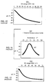
- FIGURE 4 illustrates the change in dielectric constant (or K) with temperature between 25°C and 120°C of pure barium titinate. Materials can be added to the high K barium titinate ceramic to depress the Curie peak, resulting in a formulation that has less temperature dependency. One of the trade-offs is that this tends to lower the dielectric constant. Increasing the amount of depressor decreases the amount of temperature variability.
- FIGURE 5 illustrates a prior art technique of using a depressor to depress the Curie point peak. This has the effect of making the dielectric constant of the capacitor much more stable over the operating temperature range. Materials used to depress the Curie peak usually stay in the grain boundary of the polycrystalline ceramic as opposed to Curie shifters which enter into the crystalline structure itself.
- unmodified barium titinate has a very high dielectric constant at its Curie temperature, which drops to relatively low values at a low temperature, such as room temperature at 25°C.
- a low temperature such as room temperature at 25°C.
- This relates directly to the volumetric efficiency of the finished capacitor.
- a capacitor built from pure barium titinate would have a dielectric constant of roughly 1800 at 25°C, but over 22,000 at 120°C. This capacitor would have tremendous volumetric efficiency if operated at only 120°C.
- depressors are added generally into the grain boundary of the polycrystalline ceramic. This is different from Curie point shifters, which generally enter into the crystalline structure itself. Depressors mean that the capacitor will be made more stable over temperature.
- the trade off is the sacrifice of dielectric constant.
- the dielectric constant can be depressed all the way down to below 100 and that means that its variation in dielectric constant and also capacitance will be less than 0.5% when the device is exercised over the temperature range -55 to +125°C.
- Curie point shifters are materials which can be added to barium titinate that will shift the Curie temperature to another temperature.
- lead titinate is one material that will move the Curie temperature up.
- Strontium titinate is an example of a material that will shift it downward. Shifters enter into solid-state solution with the barium titinate. The resulting misfit in the crystal lattice causes energy changes which makes the crystalline inversion occur at a different temperature.
- FIGURE 6 illustrates the concept of using prior art Curie point shifters. Shifters are materials that are added to the barium titinate that will shift the Curie temperature to another temperature. Lead titinate will generally move the Curie temperature up. Strontium titinate and other materials are examples of materials that will shift it downward.
- FIGURE 6 illustrates curve 1 which is pure barium titinate with an inherent Curie point of roughly 120°C.
- Curve 2 indicates just enough shifter to shift the Curie point to 37°C, which is body temperature. This has not been done before in a standard commercial dielectric, but would optimize the device for operation only at 37°C (body temperature).
- Curve 3 illustrates a curve with the addition of more shifter which would cause the Curie peak to occur at roughly room temperature (20°-25°C).
- FIGURE 3 There are a set of commercial dielectrics that are commonly available that are represented by FIGURE 3, including Y5V and other commercially available dielectrics.
- FIGURE 7 illustrates the propensity of a prior art 1500K and BX monolithic ceramic capacitor to drop slightly in capacitance with applied DC bias voltage. What this means is that the dielectric stress between opposed electrodes causes the crystal lattice to drop in K.
- FIGURE 8 illustrates the temperature coefficient (TC) curve of the same dielectric as described in FIGURE 7. In this case, it has an inherent dielectric constant of 1500. This illustrates the change in capacitance with temperature. As can be seen, this is a relatively stable dielectric with a Curie point of approximately 120°C. At -55°C, the capacitance drops about 9% and at +125°C, the capacitance drops approximately 7%. This is a very stable dielectric suitable for use in military and space applications. The negative trade-off is that it is not very volumetrically efficient.
- FIGURE 8 illustrates the change in capacitance with temperature of the 1500 K dielectric previously described. As one raises the dielectric constant, the capacitor becomes more volumetrically efficient. However, both the temperature stability and voltage stability of the capacitor are severely affected.
- FIGURE 9 illustrates the temperature stability of a common commercial dielectric known as Z5U. It has a dielectric constant of around 7000 and has a much greater change in capacitance over temperature stability. As one can see, the operating temperature range is narrowed. For a typical military-type capacitor, the operating temperature range would be specified for -55 to +125°C. However, the Z5U dielectric is only rated to operate between -25 and +85°C. Over this restricted operating temperature range, the capacitance drops as much as 50% in capacitance from its initial room temperature value.
- FIGURE 10 illustrates the change in capacitance with applied DC voltage in volts/mil. Assuming the same example that we previously described for the BX dielectric, as one can see, at 50 volts/mil, this dielectric drops almost 80% in capacitance. It also should be noted that the capacitance change and temperature change effects are accumulative. That is if this capacitor was operated at 125°C with 50 volts/ml bias, one would only have a few percent of the initial capacitance left. This is one reason why this particular grade of capacitor dielectric is generally not used in high reliability/mission critical applications. It is a common component in consumer electronics, such as car stereos and the like, which are generally only expected to operate at low voltage and near room temperature.
- FIGURE 11 illustrates the change in capacitance with temperature, which is even more severe than the previously described Z5U. For example, at -25°C, this particular dielectric loses 80% of its capacitance. The higher the dielectric constant is raised, the more unstable the capacitor becomes both with applied temperature and applied DC bias. At -25°C, the capacitance drops approximately 80% and at +85°C, the capacitance drops about 82%.
- FIGURE 12 represents the prior art Y5V capacitor's drop in capacitance with applied DC bias.
- a capacitor of 2 mils of fired dielectric thickness and 100 volts DC applied one has a dielectric stress of 50 volts/mil. At this 50 volt/mil stress level from the FIGURE, one can see that there is an approximate 90% drop in capacitance. This normally would be highly undesirable in an EMI filter because greatly reduced attenuation would result. While the use of this commercial dielectric might be contemplated at 37 degrees (human implant temperature), as one can see from FIGURE 11, the capacitance value will drop almost 40 degrees C as compared to the Curie peak which is between 20 and 25 degrees C.
- dielectric breakdown strength As one increases the dielectric constant, one also gives up a number of other design parameters in addition to temperature stability and voltage sensitivity.
- One of these is dielectric breakdown strength.
- the dielectric breakdown strength measured in volts/mil declines.
- FIGURE 13 generally illustrates this effect showing that as one increases the dielectric constant to above 10,000, the dielectric breakdown strength declines significantly.
- FIGURE 13 represents prior art ceramic dielectrics.
- the X-axis shows the dielectric constant and the Y-axis indicates the dielectric breakdown strength between the electrode plates measured in volts DC/mil. As one can see, in general, dielectric strength tends to drop the higher the dielectric constant.
- low K dielectrics (less than 100 K) generally have dielectric breakdown strengths of over 1000 volts/mil.
- high K commercial dielectrics that are in the range of 7000 or higher generally have dielectric breakdown strengths just slightly above 400 volts/mil. It should be noted that as you increase the K, mechanical strength is also sacrificed.
- Ferro-electric materials exhibit a number of special properties, including dielectric historisis. Ferro-electric materials are also piezoelectric, in that they have capabilities of converting mechanical movement or pressure to electrical signals or energy and visa versa. Barium titinate is generally known as a ferro-electric material when operating below its Curie point. The capacitor's ferro electric or piezoelectric behavior is a major design consideration for EMI feedthrough capacitors used in the output of implantable cardioverter defibrillators. When a high voltage pulse is applied to the EMI filter, significant mechanical stresses are generated.
- U.S. Patent Nos. 5,333,095 and 5,905,627 is that these designs allow the ceramic capacitor to expand and contract during the application of the high voltage pulse. In this way, the piezoelectric stresses are well managed.
- Alumina insulators used in the hermetic insulators of implantable medical devices. Alumina insulators have excellent mechanical properties including a very high modulus of toughness and high tensile and compressive strength. Accordingly, they make for very robust hermetic seals through which lead wires pass.
- Alumina (Al 2 O 3 ) ceramic has a very low dielectric constant (less than 7) and could not be used to make a feedthrough capacitor due to the very poor volumetric efficiency that would result.
- High K dielectrics have also been contraindicated in mission critical applications due to the general impression in the industry that they are unreliable. By unreliable, it is meant prone to failure, either due to degradation of insulation resistance, or outright electrical short (catastrophic failure).
- the present invention describes monolithic ceramic feedthrough capacitors used in combination with the hermetic seals of active implantable medical devices such as cardiac pacemakers, implantable cardioverter defibrillators (ICDs), cochlear implants, neurostimulators, and the like.
- the feedthrough capacitor dielectric is a novel very high dielectric constant material whose Curie point has been shifted to approximately 37 degrees C with very little to no Curie peak depressor. This pushes the effective K available to above 7000 (up to a maximum of approximately 22,000).
- This allows EMI feedthrough capacitors for implantable medical devices to be built in the same physical size (or even smaller) with much higher capacitance values.
- the higher capacitance provides additional attenuation to EMI caused by emitters in the frequency range from the high kilohertz all the way up to several gigahertz.
- the present invention embraces a dielectric technology wherein the capacitance value of the EMI filter can be raised to much higher levels therefore providing immunity to EMI over a much broader frequency range.
- a particular feature of the present invention is a unique property of the high dielectric constant material to decrease in capacitance with applied voltage. This is of particular advantage in output of an implantable cardioverter defibrillator (ICD). Excessive capacitance on the output leads of the ICD can degrade the pulse and also affect its energy efficiency. It is a property of high K dielectric capacitors that they drop drastically in capacitance value during the application of high voltage thereby preventing this problem. During the quiescent period, in other words, when the implantable defibrillator is not providing high voltage shock therapy, the full capacitance value is available to protect against electromagnetic interference. This is important as most EMI problems occur when the implantable device is in the cardiac signal sensing mode and detecting signals form hundreds of microvolts to several millivolts.
- the present invention relates to a novel process for manufacturing a monolithic ceramic capacitor for use in an active implantable medical device.
- the process steps include providing a dielectric material having a dielectric constant greater than 7000, adding one or more Curie point shifters to the dielectric material to optimize the monolithic ceramic capacitor dielectric constant at the human body temperature of 37°C, and processing the dielectric material with one or more shifters into a finished capacitor having first and second sets of electrode plates disposed therein.
- a dopant may be used to broaden the Curie point peak of the dielectric material, and the monolithic ceramic capacitor is typically configured as a feedthrough filter capacitor designed for incorporation into an EMI filter.
- Such a filter is useful when installed in a high voltage defibrillator circuit of an implantable medical device.
- the dielectric material is further optimized so that during the delivery of high-voltage electrical energy, such as a bi-phasic or mono-phasic fast rise time defibrillation pulse, the capacitance value of the capacitor drops to less than 65% of its initial value, and preferably less than 20% of its initial value.
- the invention comprises at least one conductive terminal pin, the novel feedthrough filter capacitor of the present invention, and a conductive ferrule through which the terminal pin passes in non-conductive relation.
- the feedthrough filter capacitor has first and second sets of electrode plates disposed within a dielectric material having a dielectric constant greater than 7000, and a first passageway through which the terminal pin extends in conductive relation with the first set of electrode plates.
- the feedthrough filter capacitor is optimized for operation within the temperature range of 30°C to 40°C, and preferably at 37°C.
- the dielectric constant of the dielectric material is within the range of 8500 to 22,000.
- the dielectric material includes at least one dopant used to shift the Curie point to 37°C. It is often necessary to include a Curie point depressor for broadening the temperature bandwidth of the Curie point peak or point of maximum dielectric constant.
- Typical dopants utilized include strontium titinate, lead titinate, zirconium dioxide, barium carbonate, zinc oxide, zinc borate, manganese carbonate, and titanium dioxide.
- Typical applications include cardiac pacemakers, ICD's, hearing implants, congestive heart failure treatment devices, atrial defibrillators, bi-ventricular pacemakers, neurostimulators, brain stimulators, bladder control stimulators, artificial eyes, artificial noses, RF muscle actuators, implanted limb manipulation systems, artificial hearts and ventricular assist devices.
- the present invention is further particularly useful in feedthrough filter capacitor assemblies for use in human implant applications utilizing an internal ground configuration.
- the assembly includes at least one conductive terminal pin, a conductive ferrule through which the terminal pin passes in non-conductive relation, the novel feedthrough filter capacitor of the present invention, and a ground lead which extends into a second passageway through the feedthrough filter capacitor, wherein the ground lead is conductively coupled to the second set of electrode plates and the conductive ferrule.
- EAS electronic article surveillance systems
- retail store's security systems security scanners, such as hand held airport wands, 10 MHz RFID systems, and the 27 MHz and 70 to 76 MHz popular operations bands for model airplanes, helicopters, boats and the like.
- the capacitance of the EMI filter would be desirably high, which is exactly the time when EMI is a concern. It has been well documented that an ICD can interpret electromagnetic interference as a fast heart rate and confuse it with ventricular tachycardia or ventricular fibrillation and thereby cause it to deliver an inappropriate and very painful high voltage shock when the patient does not need one.
- a preferred embodiment of the present invention is the use of the high K dielectric material in combination with the internally grounded feedthrough filter capacitor of U.S. Patent No. 5,905,627, or of the feedthrough filter capacitor assembly for human implant of U.S. Patent No. 5,333,095.
- Ferro ZL9000 material which is a low fire Z5U dielectric.
- Ferro XL103 which is a Z5U dielectric whose materials are listed as Figure 14.
- the Table in FIGURE 14 is taken from Ferro Electronics Materials' Company Product XL 103/Product ID 58881. This is a high K dielectric with a Curie point close to 20°C. As one can see, it employs zirconium dioxide between 1 and 5%, lead oxide between 5 and 1-%, and so on.
- the dopants including zirconium dioxide, lead oxide, zinc oxide, zinc borate and manganese carbonate
- the dopants will be varied in order to shift the Curie point to 37°C (body temperature).
- Another example is the Ferro Tamtron XL103, which has a dielectric constant of about 10,000.
- Ferro also manufactures a dielectric material known as Tamtron Y5V173L, which has a typical dielectric constant of around 18,000. In general, these high K commercially available dielectrics have Curie peaks or maximum K that are near room temperature (25°C).
- FIGURE 15 illustrates a complete process flow diagram for ceramic raw materials through final ceramic product.
- one such embodiment of the present invention would involve ceramic raw materials employing 20-30% titanium dioxide, 40-50% barium carbonate, approximately 1.5% zirconium dioxide, approximately 8.2% lead oxide and less than 1% each of zinc oxide, zinc borate and manganese carbonate with other trace elements present.
- the second from the last step in the ceramic capacitor process involves sintering/densification. This is where the capacitor is changed from a grain state into a hard fired monolithic structure.
- the firing profile can also affect Curie point and final process adjustments can be made at this point to make sure that the Curie point comes out to be 37°C.
- Strontium titinate dopant or equivalent dopants well known to those in the art are uniquely added to the ceramic raw material to rotate the Curie point to approximately 37 degrees C.
- the inherent dielectric constant can be as high as 15,000-20,000. This means that the volumetric efficiency of the ceramic capacitor can go up approximately a factor of 6 or even higher.
- FIGURE 16 illustrates alternative processing for preparation of ceramic powder all the way through slip casting and sheet storage.
- FIGURE 16 is a block diagram illustrating the various ways to process the 37°C dielectric of the present invention.
- the first step has a number of options including the possibility of spray drawing, batching H2O slurry, dry blending or jet milling.
- the powder is then taken through a particle size reduction and then followed by calcining and/or drying and then followed by a micropulverizing process (another method involves coprecipitation of the elements).
- Preparation of slip powders and binders then follows, followed by binder dispersion.
- the various components of the dielectric are carefully adjusted in order to shift the Curie peak or point of maximum K from the commonly commercially available dielectrics to a novel use specifically for human implant applications. That is, during this process the point of maximum K will be carefully designed to be at 37°C. This generally occurs during the first three basic blocks in the overall production flow diagram as illustrated.
- a preferred embodiment of the present invention would be to rotate the Curie point by adjusting the dopants and/or firing conditions so that the Curie point occurs exactly at 37°C or body temperature. This would optimize the dielectric constant.
- FIGURE 17 illustrates a unipolar capacitor 42 of the prior art constructed from dielectric material with a dielectric constant of approximately 2500.
- the capacitor of FIGURE 17 has a capacitance value of 2200 picofarads and a voltage rating of 50 volts DC.
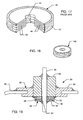
- FIGURE 18 represents the same capacitor 142 using the high K dielectric material of the present invention. This means that it has the same capacitance value, the same voltage capability, but it is much smaller. This would be made from the novel 37°C Curie point dielectric of the present invention.
- the capacitor has been dramatically reduced in size (typically, 4 to 6 times smaller).
- the capacitor can also be much higher in value (over 10,000 picofarads and/or have a much higher voltage rating. This is all due to the tremendous increase in volumetric efficiency due to the use of a dielectric with a K over 7000 (in this particular example, the K is 18,000).
- FIGURE 19 uses the same prior art hermetic terminal 38 as previously illustrated in FIGURE 2. However, as can be seen, by using the technology of the present invention, the ceramic capacitor 142 can be much smaller in physical size.
- FIGURES 20-24 illustrate a prior art internally grounded capacitor.
- the feedthrough filter capacitor 58 comprises a monolithic, ceramic internally grounded bipolar feedthrough filter capacitor 60 having three 62, 64 passageways extending therethrough.
- the outer two passageways 62 are configured to receive therethrough respective conductive terminal pins 66 and 66', and the internal diameter of the first passageways 62 are metallized to form a conductive link between the first sets of electrode plates 68 and 68'.
- the first sets of electrode plates 68 and 68' are typically silk-screened onto ceramic plates forming the feedthrough filter capacitor 60. These plates 68, 68' are surrounded by an insulative ceramic material that, for purposes of the present invention, need not be metallized on its exterior surfaces.
- a second set of electrode plates 70 is provided within the feedthrough filter capacitor 60.
- the inner diameter of the central or second passageway 64 through the feedthrough filter capacitor 60 is also metallized to conductively connect the second set of electrode plates 70, which comprise the ground plane of the feedthrough filter capacitor 60.
- the second passageway 64 is configured to receive therethrough the ground lead 72 which, in this particular embodiment, comprises a ground pin.
- the terminal pin subassembly 74 comprises a plate-like conductive ferrule 76 having three apertures therethrough that correspond to the three passageways through the feedthrough filter capacitor 60.
- the conductive terminal pins 66' are supported through the outer apertures by means of an insulator 76' (which also may be hermetic), and the ground pin 72 is supported within the central aperture by a suitable conductor 78 such as solder, an electrically conductive thermosetting material or welding/brazing.
- the feedthrough filter capacitor 60 is placed adjacent to the non-body fluid side of the conductive ferrule 76 and a conductive attachment is effected between the metallized inner diameter of the first and second passageways 62 and 64 through the feedthrough filter capacitor 60 and the respective terminal pins 66 and ground lead 72.
- the conductive connection between the terminal pins 66 and the ground lead 72 with the feedthrough filter capacitor 60 may be effected by any suitable means such as a solder or an electrically conductive thermosetting material or brazing.
- the result is the feedthrough filter capacitor assembly 58 illustrated in FIGURE 24.
- a novel aspect of this technology is that there is very low mechanical and thermal stress placed on the capacitor due to the fact that it floats on the leads and does not directly attach to the titanium ferrule.
- the titanium ferrule is designed for laser welding into the pacemaker or medical device can and is therefore, in prior art devices, subject to a great deal of thermal and mechanical stress.
- the ceramic capacitor does not see these stresses and accordingly can be much weaker in overall mechanical strength. This means that for the present invention that this is a preferred embodiment whereby the very high K dielectric material with a 37°C Curie point would be structurally very weak.
- the strength of such capacitor is no longer a major design consideration.
- FIGURES 25-27 illustrate an aspect of the present invention in that, in the same space as the bipolar capacitor of Figure 24, a six lead (hexpolar) capacitor can be designed with the same capacitance value and same voltage ratings (a three times improvement in package density). Functionally equivalent elements are given the same reference number increased by 100. This is a particularly important embodiment in light of the new bi-ventricular pacemaker and ICD devices that have been recently introduced to the market to control the ravages of congestive heart failure. These new devices feature more lead wires so that both ventricles (and the right atrium) can all be pulsed. In the drawings Figures 25-27, functionally equivalent elements shown in Figs. 20-24 are represented by the same reference number increased by 100.
- a major advantage of the present invention is that it would be possible to put much more capacitance in the present volume allowed for the feedthrough capacitor EMI filters used in conjunction with the hermetic terminals of an implantable medical devices.
- prior art feedthrough capacitor EMI filters are only effective over the frequency range of 200 MHz to 3000 MHz.
- the cutoff frequency of a low pass EMI filter is its 3 dB attenuation point.
- the EMI filter based on high dielectric constant materials would provide effective immunity against electronic article surveillance systems, frequencies used to control remote airplanes, helicopters and boats, police radio, and many other emitters that occur in the HF, VHF and UHF frequency ranges. This is particularly important in light of many reports received by the FDA of interactions between Electronic Article Surveillance Systems (EAS)(aka: retail store security systems with pedestals) and implanted medical devices. Accordingly, there is a need for much higher capacitance value EMI filters to provide effective attenuation at the frequencies at which EAS systems operate which can be as low as 58 kilohertz.
- EAS Electronic Article Surveillance Systems
- the human implant application is very unique. This is based on the fact that human body temperature is very stable and is centered right at 37°C. Another reason that these dielectrics are uniquely suited to most human implant applications is that these devices operate at extremely low voltages. Accordingly, volts/mil stress is really not an issue in a cardiac pacemaker that is putting out an output pulse of only 2 volts. The same is true for neurostimulators and cochlear devices, which operate in the microvolt region. It is also true of all pacemaker and ICD sense circuits which are detecting very low voltage level inter-cardiac signals in the microvolt to millivolt ranges.
- a unique application is in the output circuit of an implantable cardioverter defibrillator.
- a cardioverter defibrillator for most of the time is sitting in a sensing mode with literally no output voltage being supplied to its ventricle output lead wires.
- the implantable cardioverter defibrillator detects a dangerous heart arrhythmia such as ventricular fibrillation, it will charge up a high-energy storage capacitor and deliver high voltage shock therapy to the heart. It has been shown that high voltage application and fast rise time high voltage therapy will re-polarize the heart and cause it to go back into normal sinus rhythm.
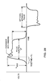
- FIGURE 28 represents a typical bi-phasic pulse which represents the therapeutic output of an implantable cardioverter defibrillator.
- V-Max typically varies from 750 volts all the way up to about 1200 volts and the pulse duration is typically in the order of 20 milliseconds.
- high K dielectrics are extremely sensitive to applied voltage. That is, they drop drastically in dielectric constant in the presence of such high voltage stress measured in volts per mil. It is a novel aspect of the present invention that a 37°C Curie point dielectric specifically designed without Curie point depressors could be used to have a very high K and accordingly a very high volumetric efficiency at body temperature only.
- the capacitor It is also desirable for the capacitor to drop drastically in capacitance during the output discharge of an implantable cardioverter defibrillator. This is because charging up the capacitor dissipates energy and therefore shortens battery life. It is also important that the output of the implantable defibrillator's solid-state electronics not be overloaded with too much capacitance. This tends to interrupt their timing and in some cases can completely preclude the proper operation of the high voltage output circuitry. Accordingly, it is a novel aspect of the present invention that the capacitance value will drop drastically during the application of the high voltage shock therapy. As an EMI filter this is not important. A typical implantable defibrillator spends most of its time not delivering therapy, but monitoring patient ventricular activity. If a dangerous ventricular arrhythmia is detected, the implantable defibrillator charges up its high energy storage capacitor and then delivers the high voltage single or bi-phasic shock.
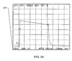
- FIGURE 29 A close up view of an actual output pulse of an implantable defibrillator is shown as FIGURE 29. As one can see, it has a very fast rise time and tends to have a droop over its 20-millisecond pulse width. Resistance to electromagnetic interference is only important when the device is not delivering its therapeutic energy, which is most of the time. However, when it is sensing cardiac activity the bias voltage on the feedthrough capacitor element is only a few millivolts. Accordingly, one will have the full benefit of the high dielectric constant in that it will be operating at a single temperature at which the dielectric constant has been optimized and also at a very low voltage bias such that it will not have a drastic drop in K and capacitance due to applied volts/mil stress. Accordingly, the use of extremely high K dielectrics which has not been previously contemplated in implantable medical devices turns out to be ideally suited for installation in an EMI filter in the output of an implantable defibrillator particularly when combined with internal ground techniques.
- a typical bi-phasic waveform has a rise time of as fast as 50 to 80 nanoseconds and a pulse width of approximately 10 milliseconds (see Figures 29 and 30). During a very short rest period, the pulse goes negative with a similar rise time and width.
- the positive and negative amplitudes of the pulse vary between 750 volts and 850 volts applied directly to cardiac tissue (with inductive ringing or overshoot, the amplitude can reach 1400 volts). It is a unique aspect of the present invention that a very high dielectric constant material be used which is very intentionally unstable in the presence of DC applied voltage. As previously mentioned, high K dielectric materials drop drastically in the presence of high volts/mil stress.
- the EMI filter In an electromagnetic interference filter, it is not necessary that the EMI filter operate as the high voltage discharge is being delivered. It is really important that the EMI filter provide effective/maximum attenuation while the device is sensing so that it does not inadvertently misfire due to the detection of electromagnetic interference (EMI can be confused as a dangerously fast heart rate caused by ventricular fibrillation). Therefore, the use of a very high dielectric constant material will provide a very high degree of electromagnetic interference attenuation at all important times, however, during the application of high voltage therapy, the capacitance value will drop drastically.
Landscapes
- Engineering & Computer Science (AREA)
- Chemical & Material Sciences (AREA)
- Manufacturing & Machinery (AREA)
- Ceramic Engineering (AREA)
- Power Engineering (AREA)
- Materials Engineering (AREA)
- Health & Medical Sciences (AREA)
- Organic Chemistry (AREA)
- Structural Engineering (AREA)
- Thermal Sciences (AREA)
- Life Sciences & Earth Sciences (AREA)
- Physics & Mathematics (AREA)
- Microelectronics & Electronic Packaging (AREA)
- Biomedical Technology (AREA)
- Nuclear Medicine, Radiotherapy & Molecular Imaging (AREA)
- Radiology & Medical Imaging (AREA)
- Inorganic Chemistry (AREA)
- Animal Behavior & Ethology (AREA)
- General Health & Medical Sciences (AREA)
- Public Health (AREA)
- Veterinary Medicine (AREA)
- Electrotherapy Devices (AREA)
- Thermistors And Varistors (AREA)
Abstract
Description
- 1.
- Reduction in size.
- 2.
- Reduction in weight.
- 3.
- Increase in longevity or battery life.
- 4.
- Increase in number of functions.
- 5.
- Reduction in cost.
- 6.
- Increase in performance.
Claims (31)
- A feedthrough filter capacitor assembly for use in an active implantable medical device, comprising:at least one conductive terminal pin;a feedthrough filter capacitor having first and second sets of electrode plates disposed within a dielectric material having a dielectric constant greater than 7000, and a first passageway through which the terminal pin extends in conductive relation with the first set of electrode plates, wherein the feedthrough filter capacitor is optimized for operation within the range of 30°C to 40°C; anda conductive ferrule through which the terminal pin passes in non-conductive relation.
- The feedthrough filter capacitor assembly of claim 1, wherein the feedthrough filter capacitor is optimized for operation and 37°C.
- The feedthrough filter capacitor assembly of claim 1, wherein the dielectric constant of the dielectric material is within the range of 8500 to 22,000.
- The feedthrough filter capacitor assembly of claim 2, wherein the dielectric material of the feedthrough filter capacitor includes at least one dopant used to shift the Curie point to 37°C.
- The feedthrough filter capacitor assembly of claim 4, including a Curie point depressor for broadening the temperature bandwidth of the Curie point peak.
- The feedthrough filter capacitor assembly of claim 4, wherein the at least one dopant is taken from the group of strontium titinate, lead titinate, zirconium dioxide, barium carbonate, zinc oxide, zinc borate, manganese carbonate, and titanium dioxide.
- The feedthrough filter capacitor assembly of claim 2, wherein the dielectric material of the feedthrough filter capacitor includes at least one dopant used to shift the point of maximum dielectric constant to 37 degrees C.
- The feedthrough filter capacitor assembly of claim 1, wherein the active implantable medical device is taken from the group of:cardiac pacemakers, ICD's, hearing implants, congestive heart failure treatment devices, atrial defibrillators, bi-ventricular pacemakers, neurostimulators, brain stimulators, bladder control stimulators, artificial eyes, artificial noses, RF muscle actuators, implanted limb manipulation systems, artificial hearts, and ventricular assist devices.
- The feedthrough filter capacitor assembly of claim 1, including an insulator disposed within the ferrule, for mounting the conductive terminal pin for passage through the conductive ferrule with the conductive terminal pin and the ferrule in non-conductive relation.
- A feedthrough filter capacitor assembly for use in active implantable medical devices, comprising: at least one conductive terminal pin;
a conductive ferrule through which the terminal then passes in non-conductive relation; a feedthrough filter capacitor having first and second sets of electrode plates disposed within a dielectric material having a dielectric constant greater than 7000, and a first passageway through which the terminal pin extends in conductive relation with the first set of electrode plates, wherein the feedthrough filter capacitor is optimized for operation at 37°C; and
a ground lead which extends into a second passageway through the feedthrough filter capacitor, wherein the ground lead is conductively coupled to the second set of electrode plates and the conductive ferrule. - The feedthrough filter capacitor assembly of claim 10, including an insulator disposed within the ferrule, for mounting the conductive terminal pin for passage through the conductive ferrule with the conductive terminal pin and the ferrule in non-conductive relation.
- The feedthrough filter capacitor assembly of claim 10, including means for hermetically sealing passage of the terminal pin through the conductive ferrule.
- The feedthrough filter capacitor assembly of claim 10, wherein the dielectric constant of the dielectric material is within the range of 8500 to 22,000.
- The feedthrough filter capacitor assembly of claim 13, wherein the dielectric material of the feedthrough filter capacitor includes at least one dopant used to shift the point of maximum dielectric constant to 37 degrees C.
- The feedthrough filter capacitor assembly of claim 14, including a Curie point depressor for broadening the temperature bandwidth of the Curie point peak.
- The feedthrough filter capacitor assembly of claim 15, wherein the at least one dopant is taken from the group of strontium titinate, lead titinate, zirconium dioxide, barium carbonate, zinc oxide, zinc borate, manganese carbonate, and titanium dioxide.
- The feedthrough filter capacitor assembly of claim 13, wherein the dielectric material of the feedthrough filter capacitor includes at least one dopant used to shift the Curie point to 37°C.
- A process for manufacturing a monolithic chip capacitor for use in an active implantable medical device, comprising the steps of:providing a dielectric material having a dielectric constant greater than 7000;adding one of more Curie point shifters to the dielectric material to optimize the monolithic chip capacitor dielectric constant at the human body temperature of 37°C; andprocessing the dielectric material with the added shifters into a finished monolithic chip capacitor having first and second sets of electrode plates disposed therein.
- The process of claim 18, including the step of adding a dopant to broaden the Curie point peak of the dielectric material.
- The process of claim 18, wherein the monolithic chip capacitor comprises a feedthrough filter capacitor.
- The process of claim 18, wherein the monolithic chip capacitor is optimized for use in an electromagnetic interference filter.
- The process of claim 18, including the step on installing the capacitor in a high-voltage defibrillator circuit of an implantable medical device.
- The process of claim 22, wherein the dielectric material is further optimized so that during the delivery of high-voltage electrical energy, capacitance value of the monolithic chip capacitor drops to less than 65% of its initial value.
- The process of claim 23, wherein the capacitance value of the monolithic chip capacitor drops to less than 20% of the initial value.
- The process of claims 23, wherein the high-voltage electrical energy comprises a bi-phasic or mono-phasic fast rise time defibrillation pulse.
- A process for manufacturing a monolithic chip capacitor for use in an active implantable medical device, comprising the steps of:providing a dielectric material having a dielectric constant greater than 7000;adding one or more Curie point shifters to the dielectric material to shift the point of maximum dielectric constant to 37 degrees C;adding a dopant to broaden the Curie point peak of the dielectric material;optimizing the dielectric material so that during the delivery of high-voltage electrical energy, capacitance value of the monolithic chip capacitor drops to less than 65% of its initial value; andprocessing the dielectric material with the added shifters and dopant into a finished monolithic chip capacitor having first and second sets of electrode plates disposed therein.
- The process of claim 26, wherein the monolithic chip capacitor comprises a feedthrough filter capacitor.
- The process of claim 27, wherein the monolithic chip capacitor is optimized for use in an electromagnetic interference filter.
- The process of claim 28, including the step on installing the capacitor in a high-voltage defibrillator circuit of an implantable medical device.
- The process of claim 26, wherein the capacitance value of the monolithic chip capacitor drops to less than 20% of the initial value.
- The process of claim 26, wherein the high-voltage electrical energy comprises a bi-phasic or mono-phasic fast rise time defibrillation pulse.
Priority Applications (1)
| Application Number | Priority Date | Filing Date | Title |
|---|---|---|---|
| EP20020021108 EP1400993B1 (en) | 2002-09-23 | 2002-09-23 | Monolithic ceramic capacitor for active implantable medical devices |
Applications Claiming Priority (1)
| Application Number | Priority Date | Filing Date | Title |
|---|---|---|---|
| EP20020021108 EP1400993B1 (en) | 2002-09-23 | 2002-09-23 | Monolithic ceramic capacitor for active implantable medical devices |
Publications (2)
| Publication Number | Publication Date |
|---|---|
| EP1400993A1 true EP1400993A1 (en) | 2004-03-24 |
| EP1400993B1 EP1400993B1 (en) | 2012-11-07 |
Family
ID=31896899
Family Applications (1)
| Application Number | Title | Priority Date | Filing Date |
|---|---|---|---|
| EP20020021108 Expired - Lifetime EP1400993B1 (en) | 2002-09-23 | 2002-09-23 | Monolithic ceramic capacitor for active implantable medical devices |
Country Status (1)
| Country | Link |
|---|---|
| EP (1) | EP1400993B1 (en) |
Cited By (6)
| Publication number | Priority date | Publication date | Assignee | Title |
|---|---|---|---|---|
| WO2006017231A1 (en) * | 2004-07-12 | 2006-02-16 | Medtronic, Inc. | Multi-polar feedthrough array for analog and/or digital communication with implantable medical device circuitry |
| WO2007037727A1 (en) * | 2005-09-28 | 2007-04-05 | St. Jude Medical Ab | Voltage protection circuits for implantable medical devices |
| WO2008067519A3 (en) * | 2006-11-30 | 2008-09-12 | Medtronic Inc | Miniaturized feedthrough |
| WO2008115240A1 (en) * | 2007-03-21 | 2008-09-25 | Medtronic, Inc. | Filtering capacitor feedthrough assembly and an implantable active medical device comprising such an assembly |
| US8593816B2 (en) | 2011-09-21 | 2013-11-26 | Medtronic, Inc. | Compact connector assembly for implantable medical device |
| CN108400775A (en) * | 2018-05-03 | 2018-08-14 | 东莞市美志电子有限公司 | A kind of high pressure resistant punching filter and the ceramics insulator applied to filter |
Citations (5)
| Publication number | Priority date | Publication date | Assignee | Title |
|---|---|---|---|---|
| US4829033A (en) * | 1986-05-05 | 1989-05-09 | Cabot Corporation | Barium titanate powders |
| WO1992008680A1 (en) * | 1990-11-08 | 1992-05-29 | Solvay | Powdered mixtures of metal oxides having dielectric properties, and dielectrics prepared therefrom |
| US5268342A (en) * | 1991-06-27 | 1993-12-07 | Murata Manufacturing Co., Ltd. | Nonreducing dielectric ceramic composition |
| US5825608A (en) * | 1996-10-18 | 1998-10-20 | Novacap, Inc. | Feed-through filter capacitor assembly |
| US5905627A (en) * | 1997-09-10 | 1999-05-18 | Maxwell Energy Products, Inc. | Internally grounded feedthrough filter capacitor |
-
2002
- 2002-09-23 EP EP20020021108 patent/EP1400993B1/en not_active Expired - Lifetime
Patent Citations (5)
| Publication number | Priority date | Publication date | Assignee | Title |
|---|---|---|---|---|
| US4829033A (en) * | 1986-05-05 | 1989-05-09 | Cabot Corporation | Barium titanate powders |
| WO1992008680A1 (en) * | 1990-11-08 | 1992-05-29 | Solvay | Powdered mixtures of metal oxides having dielectric properties, and dielectrics prepared therefrom |
| US5268342A (en) * | 1991-06-27 | 1993-12-07 | Murata Manufacturing Co., Ltd. | Nonreducing dielectric ceramic composition |
| US5825608A (en) * | 1996-10-18 | 1998-10-20 | Novacap, Inc. | Feed-through filter capacitor assembly |
| US5905627A (en) * | 1997-09-10 | 1999-05-18 | Maxwell Energy Products, Inc. | Internally grounded feedthrough filter capacitor |
Cited By (11)
| Publication number | Priority date | Publication date | Assignee | Title |
|---|---|---|---|---|
| WO2006017231A1 (en) * | 2004-07-12 | 2006-02-16 | Medtronic, Inc. | Multi-polar feedthrough array for analog and/or digital communication with implantable medical device circuitry |
| WO2007037727A1 (en) * | 2005-09-28 | 2007-04-05 | St. Jude Medical Ab | Voltage protection circuits for implantable medical devices |
| US8239026B2 (en) | 2005-09-28 | 2012-08-07 | St. Jude Medical Ab | Implantable medical device with a voltage protection circuit |
| WO2008067519A3 (en) * | 2006-11-30 | 2008-09-12 | Medtronic Inc | Miniaturized feedthrough |
| US9132268B2 (en) | 2006-11-30 | 2015-09-15 | Medtronic, Inc. | Miniaturized feedthrough |
| WO2008115240A1 (en) * | 2007-03-21 | 2008-09-25 | Medtronic, Inc. | Filtering capacitor feedthrough assembly and an implantable active medical device comprising such an assembly |
| US7917218B2 (en) | 2007-03-21 | 2011-03-29 | Medtronic, Inc. | Filtering capacitor feedthrough assembly |
| US8478409B2 (en) | 2007-03-21 | 2013-07-02 | Medtronic, Inc. | Filtering capacitor feedthrough assembly |
| US8593816B2 (en) | 2011-09-21 | 2013-11-26 | Medtronic, Inc. | Compact connector assembly for implantable medical device |
| CN108400775A (en) * | 2018-05-03 | 2018-08-14 | 东莞市美志电子有限公司 | A kind of high pressure resistant punching filter and the ceramics insulator applied to filter |
| CN108400775B (en) * | 2018-05-03 | 2024-01-30 | 东莞市美志电子有限公司 | High-voltage-resistant through filter and ceramic insulator applied to filter |
Also Published As
| Publication number | Publication date |
|---|---|
| EP1400993B1 (en) | 2012-11-07 |
Similar Documents
| Publication | Publication Date | Title |
|---|---|---|
| US6567259B2 (en) | Monolithic ceramic capacitor with barium titinate dielectric curie point optimized for active implantable medical devices operating at 37° C. | |
| US6999818B2 (en) | Inductor capacitor EMI filter for human implant applications | |
| US6456481B1 (en) | Integrated EMI filter-DC blocking capacitor | |
| US9251960B2 (en) | Dual stage EMI filter and offset highly efficient multi-polar active capacitor electrodes for an active implantable medical device | |
| US9042999B2 (en) | Low loss band pass filter for RF distance telemetry pin antennas of active implantable medical devices | |
| EP1479087B1 (en) | Emi feedthrough filter terminal assembly for human implant applications utilizing oxide resistant biostable conductive pads for reliable electrical attachments | |
| US20070123949A1 (en) | Low loss band pass filter for rf distance telemetry pin antennas of active implantable medical devices | |
| US9463329B2 (en) | Shielded three-terminal flat-through EMI/energy dissipating filter with co-fired hermetically sealed feedthrough | |
| US11071858B2 (en) | Hermetically sealed filtered feedthrough having platinum sealed directly to the insulator in a via hole | |
| EP1308971A2 (en) | Apparatus and process for the control of electromagnetic fields on the surface of emi filter capacitors | |
| EP2628504A1 (en) | EMI filtered co-connected hermetic feedthrough, feedthrough capacitor and leadwire assembly for an active implantable medical device | |
| US11541233B2 (en) | ECA oxide-resistant connection to a hermetic seal ferrule for an active implantable medical device | |
| US11633612B2 (en) | ECA oxide-resistant connection to a hermetic seal ferrule for an active implantable medical device | |
| EP3449973B1 (en) | Hermetically sealed filtered feedthrough assembly | |
| US11406817B2 (en) | Low equivalent series resistance RF filter circuit board for an active implantable medical device | |
| WO1997012645A1 (en) | Feedthrough assembly with transient voltage suppressor and emi filter for implantable medical devices | |
| EP1400993B1 (en) | Monolithic ceramic capacitor for active implantable medical devices | |
| US11369800B2 (en) | EMI feedthrough filter terminal assembly containing a laminated insulative seal | |
| EP1928546B1 (en) | Voltage protection circuits for implantable medical devices | |
| US20250256113A1 (en) | EMI Filter Feedthrough Having A Single-Sided Oxide-Resistant System Ground Opposite A System Ground To An Oxidized Surface |
Legal Events
| Date | Code | Title | Description |
|---|---|---|---|
| PUAI | Public reference made under article 153(3) epc to a published international application that has entered the european phase |
Free format text: ORIGINAL CODE: 0009012 |
|
| AK | Designated contracting states |
Kind code of ref document: A1 Designated state(s): AT BE BG CH CY CZ DE DK EE ES FI FR GB GR IE IT LI LU MC NL PT SE SK TR |
|
| AX | Request for extension of the european patent |
Extension state: AL LT LV MK RO SI |
|
| RIC1 | Information provided on ipc code assigned before grant |
Ipc: 7H 01G 4/42 A |
|
| 17P | Request for examination filed |
Effective date: 20040410 |
|
| 17Q | First examination report despatched |
Effective date: 20040830 |
|
| AKX | Designation fees paid |
Designated state(s): AT BE BG CH CY CZ DE DK EE ES FI FR GB GR IE IT LI LU MC NL PT SE SK TR |
|
| RAP1 | Party data changed (applicant data changed or rights of an application transferred) |
Owner name: GREATBATCH LTD. |
|
| GRAP | Despatch of communication of intention to grant a patent |
Free format text: ORIGINAL CODE: EPIDOSNIGR1 |
|
| GRAS | Grant fee paid |
Free format text: ORIGINAL CODE: EPIDOSNIGR3 |
|
| REG | Reference to a national code |
Ref country code: DE Ref legal event code: R079 Ref document number: 60243992 Country of ref document: DE Free format text: PREVIOUS MAIN CLASS: H01G0004420000 Ipc: H01G0004350000 |
|
| RIC1 | Information provided on ipc code assigned before grant |
Ipc: H01G 4/35 20060101AFI20120816BHEP |
|
| GRAA | (expected) grant |
Free format text: ORIGINAL CODE: 0009210 |
|
| AK | Designated contracting states |
Kind code of ref document: B1 Designated state(s): AT BE BG CH CY CZ DE DK EE ES FI FR GB GR IE IT LI LU MC NL PT SE SK TR |
|
| REG | Reference to a national code |
Ref country code: GB Ref legal event code: FG4D |
|
| REG | Reference to a national code |
Ref country code: AT Ref legal event code: REF Ref document number: 583290 Country of ref document: AT Kind code of ref document: T Effective date: 20121115 Ref country code: CH Ref legal event code: EP |
|
| REG | Reference to a national code |
Ref country code: IE Ref legal event code: FG4D |
|
| REG | Reference to a national code |
Ref country code: DE Ref legal event code: R096 Ref document number: 60243992 Country of ref document: DE Effective date: 20130103 |
|
| REG | Reference to a national code |
Ref country code: AT Ref legal event code: MK05 Ref document number: 583290 Country of ref document: AT Kind code of ref document: T Effective date: 20121107 |
|
| REG | Reference to a national code |
Ref country code: NL Ref legal event code: VDEP Effective date: 20121107 |
|
| PG25 | Lapsed in a contracting state [announced via postgrant information from national office to epo] |
Ref country code: SE Free format text: LAPSE BECAUSE OF FAILURE TO SUBMIT A TRANSLATION OF THE DESCRIPTION OR TO PAY THE FEE WITHIN THE PRESCRIBED TIME-LIMIT Effective date: 20121107 Ref country code: NL Free format text: LAPSE BECAUSE OF FAILURE TO SUBMIT A TRANSLATION OF THE DESCRIPTION OR TO PAY THE FEE WITHIN THE PRESCRIBED TIME-LIMIT Effective date: 20121107 Ref country code: FI Free format text: LAPSE BECAUSE OF FAILURE TO SUBMIT A TRANSLATION OF THE DESCRIPTION OR TO PAY THE FEE WITHIN THE PRESCRIBED TIME-LIMIT Effective date: 20121107 Ref country code: ES Free format text: LAPSE BECAUSE OF FAILURE TO SUBMIT A TRANSLATION OF THE DESCRIPTION OR TO PAY THE FEE WITHIN THE PRESCRIBED TIME-LIMIT Effective date: 20130218 |
|
| PG25 | Lapsed in a contracting state [announced via postgrant information from national office to epo] |
Ref country code: BE Free format text: LAPSE BECAUSE OF FAILURE TO SUBMIT A TRANSLATION OF THE DESCRIPTION OR TO PAY THE FEE WITHIN THE PRESCRIBED TIME-LIMIT Effective date: 20121107 Ref country code: PT Free format text: LAPSE BECAUSE OF FAILURE TO SUBMIT A TRANSLATION OF THE DESCRIPTION OR TO PAY THE FEE WITHIN THE PRESCRIBED TIME-LIMIT Effective date: 20130307 Ref country code: CY Free format text: LAPSE BECAUSE OF FAILURE TO SUBMIT A TRANSLATION OF THE DESCRIPTION OR TO PAY THE FEE WITHIN THE PRESCRIBED TIME-LIMIT Effective date: 20121107 Ref country code: GR Free format text: LAPSE BECAUSE OF FAILURE TO SUBMIT A TRANSLATION OF THE DESCRIPTION OR TO PAY THE FEE WITHIN THE PRESCRIBED TIME-LIMIT Effective date: 20130208 |
|
| PG25 | Lapsed in a contracting state [announced via postgrant information from national office to epo] |
Ref country code: AT Free format text: LAPSE BECAUSE OF FAILURE TO SUBMIT A TRANSLATION OF THE DESCRIPTION OR TO PAY THE FEE WITHIN THE PRESCRIBED TIME-LIMIT Effective date: 20121107 |
|
| PG25 | Lapsed in a contracting state [announced via postgrant information from national office to epo] |
Ref country code: DK Free format text: LAPSE BECAUSE OF FAILURE TO SUBMIT A TRANSLATION OF THE DESCRIPTION OR TO PAY THE FEE WITHIN THE PRESCRIBED TIME-LIMIT Effective date: 20121107 Ref country code: CZ Free format text: LAPSE BECAUSE OF FAILURE TO SUBMIT A TRANSLATION OF THE DESCRIPTION OR TO PAY THE FEE WITHIN THE PRESCRIBED TIME-LIMIT Effective date: 20121107 Ref country code: BG Free format text: LAPSE BECAUSE OF FAILURE TO SUBMIT A TRANSLATION OF THE DESCRIPTION OR TO PAY THE FEE WITHIN THE PRESCRIBED TIME-LIMIT Effective date: 20130207 Ref country code: SK Free format text: LAPSE BECAUSE OF FAILURE TO SUBMIT A TRANSLATION OF THE DESCRIPTION OR TO PAY THE FEE WITHIN THE PRESCRIBED TIME-LIMIT Effective date: 20121107 Ref country code: EE Free format text: LAPSE BECAUSE OF FAILURE TO SUBMIT A TRANSLATION OF THE DESCRIPTION OR TO PAY THE FEE WITHIN THE PRESCRIBED TIME-LIMIT Effective date: 20121107 |
|
| PG25 | Lapsed in a contracting state [announced via postgrant information from national office to epo] |
Ref country code: IT Free format text: LAPSE BECAUSE OF FAILURE TO SUBMIT A TRANSLATION OF THE DESCRIPTION OR TO PAY THE FEE WITHIN THE PRESCRIBED TIME-LIMIT Effective date: 20121107 |
|
| PLBE | No opposition filed within time limit |
Free format text: ORIGINAL CODE: 0009261 |
|
| STAA | Information on the status of an ep patent application or granted ep patent |
Free format text: STATUS: NO OPPOSITION FILED WITHIN TIME LIMIT |
|
| 26N | No opposition filed |
Effective date: 20130808 |
|
| REG | Reference to a national code |
Ref country code: DE Ref legal event code: R097 Ref document number: 60243992 Country of ref document: DE Effective date: 20130808 |
|
| PG25 | Lapsed in a contracting state [announced via postgrant information from national office to epo] |
Ref country code: MC Free format text: LAPSE BECAUSE OF FAILURE TO SUBMIT A TRANSLATION OF THE DESCRIPTION OR TO PAY THE FEE WITHIN THE PRESCRIBED TIME-LIMIT Effective date: 20121107 |
|
| REG | Reference to a national code |
Ref country code: CH Ref legal event code: PL |
|
| GBPC | Gb: european patent ceased through non-payment of renewal fee |
Effective date: 20130923 |
|
| REG | Reference to a national code |
Ref country code: IE Ref legal event code: MM4A |
|
| PG25 | Lapsed in a contracting state [announced via postgrant information from national office to epo] |
Ref country code: IE Free format text: LAPSE BECAUSE OF NON-PAYMENT OF DUE FEES Effective date: 20130923 Ref country code: LI Free format text: LAPSE BECAUSE OF NON-PAYMENT OF DUE FEES Effective date: 20130930 Ref country code: CH Free format text: LAPSE BECAUSE OF NON-PAYMENT OF DUE FEES Effective date: 20130930 Ref country code: GB Free format text: LAPSE BECAUSE OF NON-PAYMENT OF DUE FEES Effective date: 20130923 |
|
| PGFP | Annual fee paid to national office [announced via postgrant information from national office to epo] |
Ref country code: DE Payment date: 20140917 Year of fee payment: 13 |
|
| PGFP | Annual fee paid to national office [announced via postgrant information from national office to epo] |
Ref country code: FR Payment date: 20140906 Year of fee payment: 13 |
|
| PG25 | Lapsed in a contracting state [announced via postgrant information from national office to epo] |
Ref country code: TR Free format text: LAPSE BECAUSE OF FAILURE TO SUBMIT A TRANSLATION OF THE DESCRIPTION OR TO PAY THE FEE WITHIN THE PRESCRIBED TIME-LIMIT Effective date: 20121107 |
|
| PG25 | Lapsed in a contracting state [announced via postgrant information from national office to epo] |
Ref country code: LU Free format text: LAPSE BECAUSE OF NON-PAYMENT OF DUE FEES Effective date: 20130923 |
|
| REG | Reference to a national code |
Ref country code: DE Ref legal event code: R119 Ref document number: 60243992 Country of ref document: DE |
|
| REG | Reference to a national code |
Ref country code: FR Ref legal event code: ST Effective date: 20160531 |
|
| PG25 | Lapsed in a contracting state [announced via postgrant information from national office to epo] |
Ref country code: DE Free format text: LAPSE BECAUSE OF NON-PAYMENT OF DUE FEES Effective date: 20160401 |
|
| PG25 | Lapsed in a contracting state [announced via postgrant information from national office to epo] |
Ref country code: FR Free format text: LAPSE BECAUSE OF NON-PAYMENT OF DUE FEES Effective date: 20150930 |