EP1400929A2 - Image processing device - Google Patents
Image processing device Download PDFInfo
- Publication number
- EP1400929A2 EP1400929A2 EP20030255892 EP03255892A EP1400929A2 EP 1400929 A2 EP1400929 A2 EP 1400929A2 EP 20030255892 EP20030255892 EP 20030255892 EP 03255892 A EP03255892 A EP 03255892A EP 1400929 A2 EP1400929 A2 EP 1400929A2
- Authority
- EP
- European Patent Office
- Prior art keywords
- image
- code
- sections
- code stream
- data
- Prior art date
- Legal status (The legal status is an assumption and is not a legal conclusion. Google has not performed a legal analysis and makes no representation as to the accuracy of the status listed.)
- Granted
Links
Images


Classifications
-
- H—ELECTRICITY
- H04—ELECTRIC COMMUNICATION TECHNIQUE
- H04N—PICTORIAL COMMUNICATION, e.g. TELEVISION
- H04N19/00—Methods or arrangements for coding, decoding, compressing or decompressing digital video signals
- H04N19/40—Methods or arrangements for coding, decoding, compressing or decompressing digital video signals using video transcoding, i.e. partial or full decoding of a coded input stream followed by re-encoding of the decoded output stream
-
- H—ELECTRICITY
- H04—ELECTRIC COMMUNICATION TECHNIQUE
- H04N—PICTORIAL COMMUNICATION, e.g. TELEVISION
- H04N19/00—Methods or arrangements for coding, decoding, compressing or decompressing digital video signals
- H04N19/10—Methods or arrangements for coding, decoding, compressing or decompressing digital video signals using adaptive coding
- H04N19/102—Methods or arrangements for coding, decoding, compressing or decompressing digital video signals using adaptive coding characterised by the element, parameter or selection affected or controlled by the adaptive coding
- H04N19/132—Sampling, masking or truncation of coding units, e.g. adaptive resampling, frame skipping, frame interpolation or high-frequency transform coefficient masking
-
- H—ELECTRICITY
- H04—ELECTRIC COMMUNICATION TECHNIQUE
- H04N—PICTORIAL COMMUNICATION, e.g. TELEVISION
- H04N19/00—Methods or arrangements for coding, decoding, compressing or decompressing digital video signals
- H04N19/10—Methods or arrangements for coding, decoding, compressing or decompressing digital video signals using adaptive coding
- H04N19/134—Methods or arrangements for coding, decoding, compressing or decompressing digital video signals using adaptive coding characterised by the element, parameter or criterion affecting or controlling the adaptive coding
- H04N19/136—Incoming video signal characteristics or properties
-
- H—ELECTRICITY
- H04—ELECTRIC COMMUNICATION TECHNIQUE
- H04N—PICTORIAL COMMUNICATION, e.g. TELEVISION
- H04N19/00—Methods or arrangements for coding, decoding, compressing or decompressing digital video signals
- H04N19/10—Methods or arrangements for coding, decoding, compressing or decompressing digital video signals using adaptive coding
- H04N19/134—Methods or arrangements for coding, decoding, compressing or decompressing digital video signals using adaptive coding characterised by the element, parameter or criterion affecting or controlling the adaptive coding
- H04N19/162—User input
-
- H—ELECTRICITY
- H04—ELECTRIC COMMUNICATION TECHNIQUE
- H04N—PICTORIAL COMMUNICATION, e.g. TELEVISION
- H04N19/00—Methods or arrangements for coding, decoding, compressing or decompressing digital video signals
- H04N19/10—Methods or arrangements for coding, decoding, compressing or decompressing digital video signals using adaptive coding
- H04N19/169—Methods or arrangements for coding, decoding, compressing or decompressing digital video signals using adaptive coding characterised by the coding unit, i.e. the structural portion or semantic portion of the video signal being the object or the subject of the adaptive coding
- H04N19/17—Methods or arrangements for coding, decoding, compressing or decompressing digital video signals using adaptive coding characterised by the coding unit, i.e. the structural portion or semantic portion of the video signal being the object or the subject of the adaptive coding the unit being an image region, e.g. an object
- H04N19/174—Methods or arrangements for coding, decoding, compressing or decompressing digital video signals using adaptive coding characterised by the coding unit, i.e. the structural portion or semantic portion of the video signal being the object or the subject of the adaptive coding the unit being an image region, e.g. an object the region being a slice, e.g. a line of blocks or a group of blocks
-
- H—ELECTRICITY
- H04—ELECTRIC COMMUNICATION TECHNIQUE
- H04N—PICTORIAL COMMUNICATION, e.g. TELEVISION
- H04N19/00—Methods or arrangements for coding, decoding, compressing or decompressing digital video signals
- H04N19/48—Methods or arrangements for coding, decoding, compressing or decompressing digital video signals using compressed domain processing techniques other than decoding, e.g. modification of transform coefficients, variable length coding [VLC] data or run-length data
-
- H—ELECTRICITY
- H04—ELECTRIC COMMUNICATION TECHNIQUE
- H04N—PICTORIAL COMMUNICATION, e.g. TELEVISION
- H04N19/00—Methods or arrangements for coding, decoding, compressing or decompressing digital video signals
- H04N19/60—Methods or arrangements for coding, decoding, compressing or decompressing digital video signals using transform coding
- H04N19/63—Methods or arrangements for coding, decoding, compressing or decompressing digital video signals using transform coding using sub-band based transform, e.g. wavelets
- H04N19/64—Methods or arrangements for coding, decoding, compressing or decompressing digital video signals using transform coding using sub-band based transform, e.g. wavelets characterised by ordering of coefficients or of bits for transmission
- H04N19/645—Methods or arrangements for coding, decoding, compressing or decompressing digital video signals using transform coding using sub-band based transform, e.g. wavelets characterised by ordering of coefficients or of bits for transmission by grouping of coefficients into blocks after the transform
-
- H—ELECTRICITY
- H04—ELECTRIC COMMUNICATION TECHNIQUE
- H04N—PICTORIAL COMMUNICATION, e.g. TELEVISION
- H04N19/00—Methods or arrangements for coding, decoding, compressing or decompressing digital video signals
- H04N19/85—Methods or arrangements for coding, decoding, compressing or decompressing digital video signals using pre-processing or post-processing specially adapted for video compression
-
- H—ELECTRICITY
- H04—ELECTRIC COMMUNICATION TECHNIQUE
- H04N—PICTORIAL COMMUNICATION, e.g. TELEVISION
- H04N19/00—Methods or arrangements for coding, decoding, compressing or decompressing digital video signals
- H04N19/10—Methods or arrangements for coding, decoding, compressing or decompressing digital video signals using adaptive coding
Definitions
- the present invention relates to an image processing device, an image forming apparatus, a program, and a storage medium.
- a specific object of the present invention is to provide an image processing device capable of increasing processing speed with a simple configuration and without increasing required memory capacity when editing a compressed image.
- an image processing device comprising: an image dividing unit configured to divide an input image into a plurality of image sections; an encoding unit configured to independently encode each of the image sections, and generate a first code stream including a plurality of code sections corresponding to the image sections; and an editing unit configured to edit one of the code sections in the first code stream, and generate a second code stream based on the edited code section.
- the input image is divided into independent image sections, and these image sections are encoded independently, it is possible to independently edit any code section corresponding to an image section without decoding the code section or the whole code stream, and it is not necessary to use any special devices. As a result, it is possible to increase processing speed with a simple configuration and without increasing memory capacity.
- the editing unit may include a deletion unit configured to delete at least one of the code sections from the first code stream and output the second code stream including the remaining code sections in the first code stream. Further, the deletion unit may allocate information data indicating that the deleted code section is out of the input image to a header of the deleted code section, and output the second code stream including the remaining code sections in the first code stream and the deleted code section.
- the editing unit may include an extraction unit configured to extract at least one of the code sections from the first code stream and output the second code stream including the extracted at least one code section. Further, the extraction unit may allocate information data indicating that each of the unextracted code sections is out of the input image to a header of each of the unextracted code sections, and output the second code stream including the extracted code section and the unextracted code sections.
- the editing unit may include a selection unit configured to select at least one of the code sections from the first code stream, and a replacement unit configured to replace the selected code section with predetermined coded data and output the second code stream including the unselected code sections in the first code stream and the predetermined coded data.
- the predetermined coded data may include a plurality of pixels each having a predetermined pixel value.
- the editing unit may further include a decoding unit configured to decode the selected code section and generate first image data corresponding to the selected code section; an image data generation unit configured to generate second image data based on the first image data; and a compression unit configured to encode the second image data and generate coded data, and output the coded data to the replacement unit as the predetermined coded data.
- a decoding unit configured to decode the selected code section and generate first image data corresponding to the selected code section
- an image data generation unit configured to generate second image data based on the first image data
- a compression unit configured to encode the second image data and generate coded data, and output the coded data to the replacement unit as the predetermined coded data.
- the editing unit may further include a detection unit configured to determine a texture pixel value of the first image data output from the decoding unit; and the image data generation unit assigns the determined texture pixel value to pixels of the first image data and outputs the assigned first image data as the second image data.
- a detection unit configured to determine a texture pixel value of the first image data output from the decoding unit
- the image data generation unit assigns the determined texture pixel value to pixels of the first image data and outputs the assigned first image data as the second image data.
- the present invention it is possible to modify a part of the input image by extracting, decoding and editing an individual image section, generating a new image section and inputting the new image section to the input image.
- the pixels of the extracted image section may be modified to have other values, such as the value of the texture portion of the input image. In doing this, it is possible to naturally delete an image section or to extract an image section without leaving a hole in the input image.
- the replacement unit may replace image data of the selected code section with image data of the predetermined coded data and maintains a header of the selected code section unchanged.
- the replacement unit may replace a header and image data of the selected code section with a header and image data of the predetermined coded data, respectively.
- the replacement unit replaces a data length of the selected code section or a data length of image data of the selected code section with a data length of the predetermined coded data or a data length of image data of the predetermined coded data.
- an image forming apparatus including an image reading unit configured to read an image on a manuscript; an image processing device, comprising an image dividing unit configured to divide an input image into a plurality of image sections; an encoding unit configured to independently encode each of the image sections, and generate a first code stream including a plurality of code sections corresponding to the image sections; and an editing unit configured to edit one of the code sections in the first code stream, and generate a second code stream based on the edited code section; and a printer engine configured to form an image on a sheet of paper based on the second code stream.
- a program executed by a computer for processing an input image comprising the steps of: dividing the input image into a plurality of image sections; independently encoding each of the image sections, and generating a first code stream including a plurality of code sections corresponding to the image sections; and editing one of the code sections in the first code stream, and generating a second code stream based on the edited code section.
- a storage medium that stores a program executed by a computer for processing an input image, the program comprising the steps of: dividing the input image into a plurality of image sections; independently encoding each of the image sections, and generating a first code stream including a plurality of code sections corresponding to the image sections; and editing one of the code sections in the first code stream, and generating a second code stream based on the edited code section.
- FIG. 1 is a block diagram of an image processing device according to a first embodiment of the present invention.
- the image processing device 1 illustrated in FIG. 1, for example, is a computer that includes a CPU 2 that performs various calculations and controls parts of the image processing device 1; a memory 3 including, for example, ROM (Read Only Memory) and RAM (Randomly Access Memory); a storage device 5 such as a hard disk; an'input device 6 such as a mouse and a keyboard; a display 7 such as an LCD (Liquid Crystal Display) and a CRT (Cathode Ray Tube); a storage medium 8 such as an optical disk; a storage medium reading device 9 for reading the storage medium 8; and a communication interface (I/F) 11.
- ROM Read Only Memory
- RAM Randomly Access Memory
- a storage device 5 such as a hard disk
- an'input device 6 such as a mouse and a keyboard
- a display 7 such as an LCD (Liquid Crystal Display) and a CRT (Cathode Ray Tube)
- a storage medium 8 such as an optical disk
- storage medium reading device 9 for reading the
- a bus 4 is provided to connect the CPU 2, memory 3, storage device 5, input device 6, display 7, the storage medium reading device 9, and I/F 11.
- the image processing device 1 is connected to a network 10, for example, the Internet, through I/F 11.
- the storage medium 8 may also be any of a Magneto-optic disk (MO), a flexible disk, or any other recording medium.
- the storage medium reading device 9 may be an optical disk drive, an MO drive, a flexible disk drive, and so on.
- An image processing program for realizing the functions provided by the present invention is stored in the storage device 5.
- This image processing program may be read from the storage medium 8 by using the storage medium reading device 9, and installed in the storage device 5, or may be downloaded through the network 10 and installed in the storage device 5. After installing this image processing program in the storage device 5, the image processing device 1 becomes operable.
- This image processing program may be an independent application program, or a part of an application package; it can be made specific to a certain OS or be independent of the OS.
- FIG. 2 is a functional block diagram of the image processing device 1.
- the image processing device 1 includes an image divider 21, an encoder 22, and an editor 23.
- the image divider 21 divides an image into a number of small image sections, in other words, the image divider 21 divides image data into a series of small image data sections, and outputs the data section series to the encoder 22.
- the encoder 22 encodes each of the small image sections independently, thereby compressing the input image data and generating a code stream.
- this coding processing for example, the JPEG 2000 algorithm is used, and entropy coding with two-dimensional discrete wavelet transformation or arithmetic coding is used for encoding the input image data.
- the above "small image section" the unit division of the input image data, is equivalent to the so-called "tile" in JPEG 2000.
- the editor 23 edits each tile in the code stream generated in the encoder 22, and generates a new code stream.
- the functions of the image divider 21, the encoder 22, and the editor 23 are realized by an image processing program executed by the CPU 2.
- FIG. 3 is a diagram illustrating an example of dividing an image into tiles.
- the image divider 21 divides an input image into 16 tiles (T00 through T15).
- the encoder 22 encodes the 16 tiles separately, and the editor 23 edits the thus generated code streams.
- FIG. 4 is a diagram illustrating an example of the structure of a code stream 31 generated by encoding the tiles shown in FIG. 3.
- the code stream 31 has a main header 32 at the beginning, an EOC (End Of Code stream) 33 at the end, and 16 tiles 36 allocated and between the main header 32 and the EOC 33.
- Each of the tiles 36 is formed from a tile header 34 and a bit stream 35, and these tiles 36 are arranged in order of the tile number. [Deletion of tiles]
- FIG. 5 is a diagram showing an operation of deleting tiles from a code stream. As shown in FIG. 5, the editor 23 has a deletion unit 41. The deletion unit 41 deletes one or more tiles 36 from the code stream 31, and the remaining coded data form a new code stream 37.
- FIG. 6 is a diagram illustrating the code stream 37 after deletion of tiles from the code stream 31. As shown in FIG- 6, the tile 10 is deleted from the code stream 31, resulting in the code stream 37.
- the deletion unit 41 reads the tile numbers of the tiles 36 in the code stream 31 input to the editor 23, deletes the tile 10 from the code stream 31 as specified, and outputs the remaining coded data as the code stream 37. Because the coded data corresponding to each of the tiles 36 are independent, the tiles 36 that are not deleted are unchanged, that is, the undeleted tiles 36 are the same in the code stream 31 and in the code steam 37. Therefore, to generate the code stream 37, the coded data in the code stream 31 can be used directly. It is not necessary to encode any new data; consequently, high speed image processing is enabled.
- the tile 10 is not allocated in the new code stream 37.
- the tile 10 may also be allocated in the code stream 37, in which case the index of the tile 10, serving as the position data of the tile 10, is modified to a value not used by the system, so as to set the tile 10 out of the region of the input image. In doing so, the deleted tile will not be displayed even when it is decoded. Furthermore, by allocating the deleted tiles in the new code stream 37, it is possible to recover the original code stream 31 from the code stream 37.
- FIG. 7 is a diagram showing an operation of extracting tiles from a code stream.
- the editor 23 has an extraction unit 42.
- the extraction unit 42 extracts one or more tiles 36 from the code stream 31, and the extracted coded data form a new code stream 38.
- FIG. 8 is a diagram illustrating the code stream 38 formed by tiles extracted from the code stream 31. As shown in FIG. 8, the tile 10 is extracted from the code stream 31, and the tile 10 forms the code stream 38.
- the extraction unit 42 reads the tile numbers of the tiles 36 in the code stream 31 input to the editor 23, extracts the tile 10 from the code stream 31 as designated, and outputs the extracted coded data as the code stream 38. Because the coded data corresponding to each of the tiles 36 are independent, the extracted coded data in the code stream 38 are the same as the coded data of the tile 10 in the code stream 31. That is, to generate the code stream 38, the coded data in the code stream 31 can be used directly, and it is not necessary to encode any new data; therefore, it is possible to perform high speed image processing.
- other unextracted tiles in the code stream 31 may also be allocated in the code stream 38, but the indices of these tiles, serving as the position data of the tiles, are modified to values not used by the system, so as to set these tiles out of the region of the input image. In doing so, these unextracted tiles will not be displayed even though they are decoded. Furthermore, by allocating the unextracted tiles in the new code stream 38, it is possible to recover the original code stream 31 from the code stream 38.
- FIG. 9 is a diagram showing a configuration. for executing the operation of replacing tiles in a code stream with other data.
- the editor 23 has a selection unit 43 and a replacement unit 44.
- the selection unit 43 selects one or more tiles from the code stream 31, and the replacement unit 44 replaces the selected tiles with other coded data, and outputs a new code stream 39.
- FIG. 10 is a diagram illustrating the code stream 39 generated after replacing tiles in the code stream 31. As shown in FIG. 10, coded data of the tile 10 in the code stream 31 is selected and replaced with coded data of a tile 10', resulting in the code stream 39.
- the coded data of the tile 10' may be coded data of a prepared image compressed by using the JPEG 2000 algorithm.
- Each pixel in the prepared image may be assigned any value, for example, data indicating white color (in the case of 8 bit pixel data, the possible value ranges from 0 through 255, and white color is equivalent to 0) may be assigned and encoded, or data indicating the texture of the original image represented by the code stream 31 may also be assigned to pixels in the prepared image.
- the replacement unit 44 may replace both the tile header 34 and the bit stream 35 of the selected tiles, or just replace the bit stream 35, because it is sufficient for image editing. In the latter case, however, since length of the tile header 34 or the bit stream 35 may change, length of the tile header 34 or the bit stream 35 should be rewritten.
- FIG. 11 is a block diagram showing another configuration for executing the operation of replacing tiles in a code stream.
- the editor 23 may include the selection unit 43, a decoder 45, an image data generating unit 46, a compressing unit 47, and the replacement unit 44.
- the selection unit 43 selects one or more tiles from the code stream 31, the decoder 45 decodes the selected tiles, the image data generating unit 46 generates new image data based on the image data of the decoded tiles, the compressing unit 47 encodes and compresses the new image data by using the JPEG 2000 algorithm, and the replacement unit 44 replaces the selected tiles with the coded data output from the compressing unit 47, and outputs a new code stream 60.
- the image data generating unit 46 may have various tools for processing image data, enabling a user to edit the selected tiles in any desired way.
- FIGS. 12A through 12C are views illustrating image processing by the configuration shown in FIG. 11.
- an original image is divided into 16 tiles represented by T00 through T15 in order, similar to FIG. 3.
- the tile 10 is selected from the original image, and the image of the tile 10 is edited by a user in the way described above, and this generates a new image, corresponding to the tile 10'.
- the tile 10 in the original image is replaced by the tile 10', forming a new image as shown in FIG. 12C corresponding to the code stream 60.
- FIG. 13 is a block diagram showing still another configuration for executing the operation of replacing tiles in a code stream.
- the editor 23 may include the selection unit 43, the decoder 45, a texture detection unit 48, the image data generating unit 46, the compressing unit 47, and the replacement unit 44.
- the selection unit 43 selects one or more tiles from the code stream 31, and the decoder 45 decodes the selected tiles.
- the texture detection unit 48 detects pixel values of the texture portion in the image obtained by decoding the selected tiles. For example, the texture detection unit 48 counts the pixel values of the pixels in the selected image, and determines the pixel value that appears most frequently to be the pixel value of the texture portion.
- the image data generating unit 46 generates a new image in which the pixel values of all pixels are set to the determined texture pixel value.
- the compressing unit 47 encodes and compresses the new image data by using the JPEG 2000 algorithm, and the replacement unit 44 replaces the selected tiles with the coded data output from the compressing unit 47, and outputs a new code stream 61.
- FIG. 14 is a block diagram showing a configuration of an image forming apparatus according to an embodiment of the present invention.
- the image forming apparatus 51 shown in FIG. 14, for example, is a digital copy machine, and includes an image reading unit 52 such as a scanner, an image data control unit 53, an image processing unit 54, an image data storage unit 55, an image data writing unit 56 equipped with a print engine, an operational panel 57, and a communication interface 58.
- the image reading unit 52 irradiates light to a document and detects the light reflected by the document using a CCD (Charge Coupled Device), which converts the light to electrical signals, and digitalizes the electrical signals by an A/D converter.
- CCD Charge Coupled Device
- the image data control unit 53 controls the other units.
- the image data control unit 53 has interfaces with the other units, and controls data transfer with the other units through the interfaces.
- the image data storage unit 55 stores image data under instructions of the image data control unit 53.
- the image data writing unit 56 controlled by the image data control unit 53, prints an image on a medium, such as a piece of paper, based on an input image.
- the image data writing unit 56' may print the image on the medium by means of, for example, electrophotography, inkjet, dye-sublimation heat transfer, silver salt imaging, direct thermal printing, and thermal Wax transfer.
- the operational panel 57 includes a keyboard for a user to conduct operations, and a display for presenting images or messages.
- the communication interface 58 is used to connect the digital copy machine 51 with computers on the outside for data transfer between them.
- the image processing unit 54 is formed from any image processing device as described in the first embodiment. It performs various processing on image data transmitted from the image reading unit 52 or the communication interface 58.
- the image processing unit 54 encodes and compresses input image data using the JPEG 2000 algorithm, and is capable of changing the image size, changing image positions, and so on.
- FIG. 15 is a block diagram showing a hardware configuration of a portion of the image processing unit 54.
- the image processing unit 54 includes a CPU 61, a ROM 62, and a RAM 63, and they are connected by the bus 64.
- the ROM 62 an image processing program is stored, and the CPU 61 executes the image processing program while using the RAM 63 as a working area thereof to realize functions as illustrated by FIG. 2, FIG. 9, FIG, 11, and FIG. 13, generates code streams as described in the first embodiment, and edits thus generated code streams in various ways.
- the image processing unit 54 performs various processing on image data transmitted from the image reading unit 52 and the communication interface 58.
- the image processing unit 54 encodes and compresses input image data using the JPEG 2000 algorithm, and stores the resultant code stream in the image data storage unit 55.
- the image processing unit 54 reads out the code stream from the image data storage unit 55, and edits the code stream in various ways.
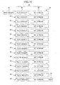
- FIG. 16 is a flow chart showing the operation of the digital copy machine 51 when editing a code stream of an image.
- step S1 a user operates the operation panel 57 to input a command for reading in an. image.
- step S2 image data are transmitted from the image reading unit 52 or the communication interface 58.
- step S3 the image is displayed on the display on the operation panel 57.
- step 54 tiles in the image are assigned numbers, and the tiles are displayed together with the numbers. Then the user is queried whether image editing is to be performed, If image editing is to be performed, the routine proceeds to step S5. (Note: In FIG. 16 S5 change "EDITION” to "EDITING".) If image editing is not to be performed, the routine proceeds to step S13.
- step S5 if the user desires to edit the image, the user is further queried about which kind of editing is to be performed. For example, the user is requested to choose one of image partial deletion, image partial extraction, and image partial replacement.
- step S6 if the user chooses partial deletion in step S5, the user further specifies the number (s) of the tile(s) to be deleted from the image on the display.
- step S7 if the user chooses partial extraction in step S5, the user further specifies the number(s) of the tile(s) to be extracted from the image on the display,
- step S8 if the user chooses partial replacement in step S5, the user further specifies the' number(s) of the tile(s) to be replaced in the image on the display.
- step S9 the user specifies paper size to be used for printing the resultant image.
- step S10 the user pushes the execution button on the operational panel 57.
- step S11 depending on the choice made in step S5, one of image partial deletion, image partial extraction, and image partial replacement is executed to edit the input image.
- image partial deletion, image partial extraction, and image partial replacement is executed to edit the input image.
- This hole can be filled, for example, by embedding an image whose pixels have the value of the texture portion of the tiles to be replaced.
- the pixel value of the texture portion can be determined by the texture detection unit 48 in FIG. 13.
- step 512 after processing in step S11, the resultant code stream is stored in the image data storage unit 55.
- step S13 if image editing is not to be performed, as decided in step S4, the input image data are encoded and compressed by using JPEG 2000, and a code stream is generated. This code stream is also stored in the image data storage unit 55 in step S12.
- step S14 the code stream is transmitted to the image data writing unit 56, and the corresponding image is printed on the paper of the specified size.
- the input image is divided into image sections, and these image sections are encoded independently, it is possible to independently edit any code section corresponding to an image section without decoding the code section or the whole code stream, and it is not necessary to use any special devices. As a result, it is possible to increase processing speed with a simple configuration and without increasing memory capacity,
- the pixels of the extracted image section may be modified to have other values, such as the value of the texture portion of the input image, In doing this, it is possible to naturally delete an image section or to extract an image section without leaving a hole in the input image.
Abstract
Description
- The present invention relates to an image processing device, an image forming apparatus, a program, and a storage medium.
- In the conventional technique of editing images compressed by the JPEG algorithm, in order to edit a compressed image, the whole 'compressed image has to be decoded first to obtain the original uncompressed image, and then the uncompressed image is edited. This technique requires a relatively large memory capacity, and is difficult to achieve high speed image processing.
- To solve the problem, techniques have been proposed to index sections of an image compressed by the JPEG algorithm. For example, Japanese Laid Open Patent Application No. 6-46243 and Japanese Laid Open Patent Application No. 7-170390 disclose such techniques.
- However, techniques disclosed in Japanese Laid Open Patent Application No. 6-46243 and Japanese Laid Open Patent Application No. 7-170390 require special devices for dealing with data generated by DPCM (differential Pulse Coding Modulation) in JPEG. This results in a complicated configuration of the system, and high manufacturing cost.
- Accordingly, it is a general object of the present invention to solve one or more problems of the related art.
- A specific object of the present invention is to provide an image processing device capable of increasing processing speed with a simple configuration and without increasing required memory capacity when editing a compressed image.
- According to a first aspect of the present invention, there is provided an image processing device, comprising: an image dividing unit configured to divide an input image into a plurality of image sections; an encoding unit configured to independently encode each of the image sections, and generate a first code stream including a plurality of code sections corresponding to the image sections; and an editing unit configured to edit one of the code sections in the first code stream, and generate a second code stream based on the edited code section.
- According to the present invention, because the input image is divided into independent image sections, and these image sections are encoded independently, it is possible to independently edit any code section corresponding to an image section without decoding the code section or the whole code stream, and it is not necessary to use any special devices. As a result, it is possible to increase processing speed with a simple configuration and without increasing memory capacity.
- The editing unit may include a deletion unit configured to delete at least one of the code sections from the first code stream and output the second code stream including the remaining code sections in the first code stream. Further, the deletion unit may allocate information data indicating that the deleted code section is out of the input image to a header of the deleted code section, and output the second code stream including the remaining code sections in the first code stream and the deleted code section.
- In addition, the editing unit may include an extraction unit configured to extract at least one of the code sections from the first code stream and output the second code stream including the extracted at least one code section. Further, the extraction unit may allocate information data indicating that each of the unextracted code sections is out of the input image to a header of each of the unextracted code sections, and output the second code stream including the extracted code section and the unextracted code sections.
- In addition, the editing unit may include a selection unit configured to select at least one of the code sections from the first code stream, and a replacement unit configured to replace the selected code section with predetermined coded data and output the second code stream including the unselected code sections in the first code stream and the predetermined coded data. Further, the predetermined coded data may include a plurality of pixels each having a predetermined pixel value.
- According to the present invention, it is possible to perform editing such as deletion, extraction, and replacement of individual image sections and output various kinds of code streams.
- The editing unit may further include a decoding unit configured to decode the selected code section and generate first image data corresponding to the selected code section; an image data generation unit configured to generate second image data based on the first image data; and a compression unit configured to encode the second image data and generate coded data, and output the coded data to the replacement unit as the predetermined coded data.
- The editing unit may further include a detection unit configured to determine a texture pixel value of the first image data output from the decoding unit; and the image data generation unit assigns the determined texture pixel value to pixels of the first image data and outputs the assigned first image data as the second image data.
- According to the present invention, it is possible to modify a part of the input image by extracting, decoding and editing an individual image section, generating a new image section and inputting the new image section to the input image. For example, the pixels of the extracted image section may be modified to have other values, such as the value of the texture portion of the input image. In doing this, it is possible to naturally delete an image section or to extract an image section without leaving a hole in the input image.
- The replacement unit may replace image data of the selected code section with image data of the predetermined coded data and maintains a header of the selected code section unchanged. Alternatively, the replacement unit may replace a header and image data of the selected code section with a header and image data of the predetermined coded data, respectively. Further, when replacing the selected code section with the predetermined coded data, the replacement unit replaces a data length of the selected code section or a data length of image data of the selected code section with a data length of the predetermined coded data or a data length of image data of the predetermined coded data.
- As an embodiment of the present invention, the encoding unit may encode each of the image sections by using one of entropy coding with two-dimensional discrete wavelet transformation and arithmetic coding'. Further, the encoding unit may encode each of the image sections by using the JPEG 2000 algorithm; and each of the image sections corresponds to a tile in the JPEG 2000 algorithm. In this case, the height and the width of the tile are multiples of a quantity d = 2L, where L is the wavelet decomposition level.
- According to the present invention, it is possible to edit each individual tile without being affected by wavelet division.
- According to a second aspect of the present invention, there is provided an image forming apparatus including an image reading unit configured to read an image on a manuscript; an image processing device, comprising an image dividing unit configured to divide an input image into a plurality of image sections; an encoding unit configured to independently encode each of the image sections, and generate a first code stream including a plurality of code sections corresponding to the image sections; and an editing unit configured to edit one of the code sections in the first code stream, and generate a second code stream based on the edited code section; and a printer engine configured to form an image on a sheet of paper based on the second code stream.
- According to a third aspect of the present invention, there is provided a program executed by a computer for processing an input image, comprising the steps of: dividing the input image into a plurality of image sections; independently encoding each of the image sections, and generating a first code stream including a plurality of code sections corresponding to the image sections; and editing one of the code sections in the first code stream, and generating a second code stream based on the edited code section.
- According to a fourth aspect of the present invention, there is provided a storage medium that stores a program executed by a computer for processing an input image, the program comprising the steps of: dividing the input image into a plurality of image sections; independently encoding each of the image sections, and generating a first code stream including a plurality of code sections corresponding to the image sections; and editing one of the code sections in the first code stream, and generating a second code stream based on the edited code section.
- These and other objects, features, and advantages of the present invention will become more apparent from the following detailed description of preferred embodiments given with reference to the accompanying drawings in which:
- FIG. 1 is a block diagram of an image processing device according to a first embodiment of the present invention;
- FIG. 2 is a functional block diagram of the
image processing device 1; - FIG. 3 is a diagram illustrating an example of dividing an image into tiles;
- FIG. 4 is a data diagram illustrating an
example of the structure of.a
code stream 31 generated by encoding the tiles shown in FIG. 3; - FIG. 5 is a schematic diagram showing operation of deleting tiles from a code stream;
- FIG. 6 is a data diagram illustrating the
code stream 37 after deletion of tiles from thecode stream 31; - FIG. 7 is a schematic diagram showing operation of extracting tiles from a code stream;
- FIG. 8 is a data diagram illustrating the
code stream 38 formed by tiles extracted from thecode stream 31; - FIG. 9 is a schematic diagram showing a configuration for executing the operation of replacing tiles in a code stream with other data;
- FIG. 10 is a data diagram illustrating the
code stream 39 generated after replacing tiles in thecode stream 31; - FIG. 11 is a block diagram showing another configuration for executing the operation of replacing tiles in a code stream;
- FIGs. 12A through 12C are tiled images illustrating image processing by the configuration shown in FIG. 11;
- FIG. 13 is a block diagram showing still another configuration for executing the operation of replacing tiles in a code stream;
- FIG. 14 is a block diagram showing a configuration of an image forming apparatus according to a second embodiment of the present invention;
- FIG. 15 is a block diagram showing a
hardware configuration of a portion of the
image processing unit 54; and - FIG. 16 is a flow chart showing the
operation of the
digital copy machine 51 when editing a code stream of an image. -
- Below, preferred embodiments of the present invention are explained with reference to the accompanying drawings.
- FIG. 1 is a block diagram of an image processing device according to a first embodiment of the present invention.
- The
image processing device 1 illustrated in FIG. 1, for example, is a computer that includes aCPU 2 that performs various calculations and controls parts of theimage processing device 1; amemory 3 including, for example, ROM (Read Only Memory) and RAM (Randomly Access Memory); a storage device 5 such as a hard disk; an'inputdevice 6 such as a mouse and a keyboard; adisplay 7 such as an LCD (Liquid Crystal Display) and a CRT (Cathode Ray Tube); astorage medium 8 such as an optical disk; a storagemedium reading device 9 for reading thestorage medium 8; and a communication interface (I/F) 11. - A
bus 4 is provided to connect theCPU 2,memory 3, storage device 5,input device 6,display 7, the storagemedium reading device 9, and I/F 11. Theimage processing device 1 is connected to anetwork 10, for example, the Internet, through I/F 11. - In addition to an
optical disk 8, such as a CD and a DVD, thestorage medium 8 may also be any of a Magneto-optic disk (MO), a flexible disk, or any other recording medium. According to the specific type of thestorage medium 8, the storagemedium reading device 9 may be an optical disk drive, an MO drive, a flexible disk drive, and so on. - An image processing program for realizing the functions provided by the present invention is stored in the storage device 5. This image processing program may be read from the
storage medium 8 by using the storagemedium reading device 9, and installed in the storage device 5, or may be downloaded through thenetwork 10 and installed in the storage device 5. After installing this image processing program in the storage device 5, theimage processing device 1 becomes operable. This image processing program may be an independent application program, or a part of an application package; it can be made specific to a certain OS or be independent of the OS. - FIG. 2 is a functional block diagram of the
image processing device 1. - As shown in FIG, 2, functionally, the
image processing device 1 includes animage divider 21, anencoder 22, and aneditor 23. - The
image divider 21 divides an image into a number of small image sections, in other words, theimage divider 21 divides image data into a series of small image data sections, and outputs the data section series to theencoder 22. - The
encoder 22 encodes each of the small image sections independently, thereby compressing the input image data and generating a code stream. In this coding processing, for example, the JPEG 2000 algorithm is used, and entropy coding with two-dimensional discrete wavelet transformation or arithmetic coding is used for encoding the input image data. Hence, the above "small image section", the unit division of the input image data, is equivalent to the so-called "tile" in JPEG 2000. - The
editor 23 edits each tile in the code stream generated in theencoder 22, and generates a new code stream. - The functions of the
image divider 21, theencoder 22, and theeditor 23 are realized by an image processing program executed by theCPU 2. - When using the JPEG 2000 algorithm, assuming L represents the level of wavelet division, and d = 2L, if the width and height of the tile are multiples of d, the size of the tile is not influenced by the wavelet division, and hence it is possible to edit each tile independently.
- Below, processing by the
editor 23 is described in detail. - FIG. 3 is a diagram illustrating an example of dividing an image into tiles. As shown in FIG. 3, the
image divider 21 divides an input image into 16 tiles (T00 through T15). Theencoder 22 encodes the 16 tiles separately, and theeditor 23 edits the thus generated code streams. - FIG. 4 is a diagram illustrating an example of the structure of a
code stream 31 generated by encoding the tiles shown in FIG. 3. As illustrated in FIG. 4, thecode stream 31 has amain header 32 at the beginning, an EOC (End Of Code stream) 33 at the end, and 16tiles 36 allocated and between themain header 32 and theEOC 33. Each of thetiles 36 is formed from atile header 34 and abit stream 35, and thesetiles 36 are arranged in order of the tile number. [Deletion of tiles] - FIG. 5 is a diagram showing an operation of deleting tiles from a code stream. As shown in FIG. 5, the
editor 23 has adeletion unit 41. Thedeletion unit 41 deletes one ormore tiles 36 from thecode stream 31, and the remaining coded data form anew code stream 37. - FIG. 6 is a diagram illustrating the
code stream 37 after deletion of tiles from thecode stream 31. As shown in FIG- 6, thetile 10 is deleted from thecode stream 31, resulting in thecode stream 37. - Specifically, the
deletion unit 41 reads the tile numbers of thetiles 36 in thecode stream 31 input to theeditor 23, deletes thetile 10 from thecode stream 31 as specified, and outputs the remaining coded data as thecode stream 37. Because the coded data corresponding to each of thetiles 36 are independent, thetiles 36 that are not deleted are unchanged, that is, theundeleted tiles 36 are the same in thecode stream 31 and in thecode steam 37. Therefore, to generate thecode stream 37, the coded data in thecode stream 31 can be used directly. It is not necessary to encode any new data; consequently, high speed image processing is enabled. - In FIG. 6, it is shown that after deletion of the
tile 10 from thecode stream 31, thetile 10 is not allocated in thenew code stream 37. As an alternative, thetile 10 may also be allocated in thecode stream 37, in which case the index of thetile 10, serving as the position data of thetile 10, is modified to a value not used by the system, so as to set thetile 10 out of the region of the input image. In doing so, the deleted tile will not be displayed even when it is decoded. Furthermore, by allocating the deleted tiles in thenew code stream 37, it is possible to recover theoriginal code stream 31 from thecode stream 37. - FIG. 7 is a diagram showing an operation of extracting tiles from a code stream. As shown in FIG. 7, the
editor 23 has anextraction unit 42. Theextraction unit 42 extracts one ormore tiles 36 from thecode stream 31, and the extracted coded data form anew code stream 38. - FIG. 8 is a diagram illustrating the
code stream 38 formed by tiles extracted from thecode stream 31. As shown in FIG. 8, thetile 10 is extracted from thecode stream 31, and thetile 10 forms thecode stream 38. - Specifically, the
extraction unit 42 reads the tile numbers of thetiles 36 in thecode stream 31 input to theeditor 23, extracts thetile 10 from thecode stream 31 as designated, and outputs the extracted coded data as thecode stream 38. Because the coded data corresponding to each of thetiles 36 are independent, the extracted coded data in thecode stream 38 are the same as the coded data of thetile 10 in thecode stream 31. That is, to generate thecode stream 38, the coded data in thecode stream 31 can be used directly, and it is not necessary to encode any new data; therefore, it is possible to perform high speed image processing. - Similar to the aforesaid deletion processing, in addition to the
tile 10, other unextracted tiles in thecode stream 31 may also be allocated in thecode stream 38, but the indices of these tiles, serving as the position data of the tiles, are modified to values not used by the system, so as to set these tiles out of the region of the input image. In doing so, these unextracted tiles will not be displayed even though they are decoded. Furthermore, by allocating the unextracted tiles in thenew code stream 38, it is possible to recover theoriginal code stream 31 from thecode stream 38. - FIG. 9 is a diagram showing a configuration. for executing the operation of replacing tiles in a code stream with other data. As shown in FIG. 9, the
editor 23 has aselection unit 43 and areplacement unit 44. Theselection unit 43 selects one or more tiles from thecode stream 31, and thereplacement unit 44 replaces the selected tiles with other coded data, and outputs anew code stream 39. - FIG. 10 is a diagram illustrating the
code stream 39 generated after replacing tiles in thecode stream 31. As shown in FIG. 10, coded data of thetile 10 in thecode stream 31 is selected and replaced with coded data of a tile 10', resulting in thecode stream 39. - For example, the coded data of the tile 10' may be coded data of a prepared image compressed by using the JPEG 2000 algorithm. Each pixel in the prepared image may be assigned any value, for example, data indicating white color (in the case of 8 bit pixel data, the possible value ranges from 0 through 255, and white color is equivalent to 0) may be assigned and encoded, or data indicating the texture of the original image represented by the
code stream 31 may also be assigned to pixels in the prepared image. - It should be noted that when the
replacement unit 44 replaces the selected tiles with other coded data, thereplacement unit 44 may replace both thetile header 34 and thebit stream 35 of the selected tiles, or just replace thebit stream 35, because it is sufficient for image editing. In the latter case, however, since length of thetile header 34 or thebit stream 35 may change, length of thetile header 34 or thebit stream 35 should be rewritten. - FIG. 11 is a block diagram showing another configuration for executing the operation of replacing tiles in a code stream. As shown in FIG, 11, the
editor 23 may include theselection unit 43, adecoder 45, an imagedata generating unit 46, a compressingunit 47, and thereplacement unit 44. - The
selection unit 43 selects one or more tiles from thecode stream 31, thedecoder 45 decodes the selected tiles, the imagedata generating unit 46 generates new image data based on the image data of the decoded tiles, the compressingunit 47 encodes and compresses the new image data by using the JPEG 2000 algorithm, and thereplacement unit 44 replaces the selected tiles with the coded data output from the compressingunit 47, and outputs anew code stream 60. - In this configuration, the image
data generating unit 46 may have various tools for processing image data, enabling a user to edit the selected tiles in any desired way. - FIGS. 12A through 12C are views illustrating image processing by the configuration shown in FIG. 11. As shown in FIG.' 12A, an original image is divided into 16 tiles represented by T00 through T15 in order, similar to FIG. 3. As shown in FIG. 12B, the
tile 10 is selected from the original image, and the image of thetile 10 is edited by a user in the way described above, and this generates a new image, corresponding to the tile 10'. - In FIG. 12C, the
tile 10 in the original image is replaced by the tile 10', forming a new image as shown in FIG. 12C corresponding to thecode stream 60. - FIG. 13 is a block diagram showing still another configuration for executing the operation of replacing tiles in a code stream. As shown in FIG. 13, the
editor 23 may include theselection unit 43, thedecoder 45, atexture detection unit 48, the imagedata generating unit 46, the compressingunit 47, and thereplacement unit 44. - The
selection unit 43 selects one or more tiles from thecode stream 31, and thedecoder 45 decodes the selected tiles. Thetexture detection unit 48 detects pixel values of the texture portion in the image obtained by decoding the selected tiles. For example, thetexture detection unit 48 counts the pixel values of the pixels in the selected image, and determines the pixel value that appears most frequently to be the pixel value of the texture portion. The imagedata generating unit 46 generates a new image in which the pixel values of all pixels are set to the determined texture pixel value. The compressingunit 47 encodes and compresses the new image data by using the JPEG 2000 algorithm, and thereplacement unit 44 replaces the selected tiles with the coded data output from the compressingunit 47, and outputs anew code stream 61. - FIG. 14 is a block diagram showing a configuration of an image forming apparatus according to an embodiment of the present invention.
- The
image forming apparatus 51 shown in FIG. 14, for example, is a digital copy machine, and includes animage reading unit 52 such as a scanner, an imagedata control unit 53, animage processing unit 54, an imagedata storage unit 55, an imagedata writing unit 56 equipped with a print engine, anoperational panel 57, and acommunication interface 58. - The
image reading unit 52 irradiates light to a document and detects the light reflected by the document using a CCD (Charge Coupled Device), which converts the light to electrical signals, and digitalizes the electrical signals by an A/D converter. - The image
data control unit 53 controls the other units. In addition, the imagedata control unit 53 has interfaces with the other units, and controls data transfer with the other units through the interfaces. - The image
data storage unit 55 stores image data under instructions of the imagedata control unit 53. - The image
data writing unit 56, controlled by the imagedata control unit 53, prints an image on a medium, such as a piece of paper, based on an input image. The image data writing unit 56'may print the image on the medium by means of, for example, electrophotography, inkjet, dye-sublimation heat transfer, silver salt imaging, direct thermal printing, and thermal Wax transfer. - The
operational panel 57 includes a keyboard for a user to conduct operations, and a display for presenting images or messages. - The
communication interface 58 is used to connect thedigital copy machine 51 with computers on the outside for data transfer between them. - The
image processing unit 54 is formed from any image processing device as described in the first embodiment. It performs various processing on image data transmitted from theimage reading unit 52 or thecommunication interface 58. For example, theimage processing unit 54 encodes and compresses input image data using the JPEG 2000 algorithm, and is capable of changing the image size, changing image positions, and so on. - FIG. 15 is a block diagram showing a hardware configuration of a portion of the
image processing unit 54. As shown in FIG. 15, theimage processing unit 54 includes aCPU 61, aROM 62, and aRAM 63, and they are connected by thebus 64. - In the
ROM 62 an image processing program is stored, and theCPU 61 executes the image processing program while using theRAM 63 as a working area thereof to realize functions as illustrated by FIG. 2, FIG. 9, FIG, 11, and FIG. 13, generates code streams as described in the first embodiment, and edits thus generated code streams in various ways. - In the editing processing, the
image processing unit 54 performs various processing on image data transmitted from theimage reading unit 52 and thecommunication interface 58. For example, theimage processing unit 54 encodes and compresses input image data using the JPEG 2000 algorithm, and stores the resultant code stream in the imagedata storage unit 55. When necessary, theimage processing unit 54 reads out the code stream from the imagedata storage unit 55, and edits the code stream in various ways. - FIG. 16 is a flow chart showing the operation of the
digital copy machine 51 when editing a code stream of an image. - In step S1, a user operates the
operation panel 57 to input a command for reading in an. image. - In step S2, image data are transmitted from the
image reading unit 52 or thecommunication interface 58. - In step S3, the image is displayed on the display on the
operation panel 57. - In
step 54, tiles in the image are assigned numbers, and the tiles are displayed together with the numbers. Then the user is queried whether image editing is to be performed, If image editing is to be performed, the routine proceeds to step S5. (Note: In FIG. 16 S5 change "EDITION" to "EDITING".) If image editing is not to be performed, the routine proceeds to step S13. - In step S5, if the user desires to edit the image, the user is further queried about which kind of editing is to be performed. For example, the user is requested to choose one of image partial deletion, image partial extraction, and image partial replacement.
- In step S6, if the user chooses partial deletion in step S5, the user further specifies the number (s) of the tile(s) to be deleted from the image on the display.
- In step S7, if the user chooses partial extraction in step S5, the user further specifies the number(s) of the tile(s) to be extracted from the image on the display,
- In step S8, if the user chooses partial replacement in step S5, the user further specifies the' number(s) of the tile(s) to be replaced in the image on the display.
- In step S9, the user specifies paper size to be used for printing the resultant image.
- In step S10, the user pushes the execution button on the
operational panel 57. - In step S11, depending on the choice made in step S5, one of image partial deletion, image partial extraction, and image partial replacement is executed to edit the input image. The details of these processes are described in the first embodiment, and are omitted here.
- When replacing a part of the input image, there appears a hole (an area lacking image data) in the input image. This hole can be filled, for example, by embedding an image whose pixels have the value of the texture portion of the tiles to be replaced. The pixel value of the texture portion can be determined by the
texture detection unit 48 in FIG. 13. - In step 512, after processing in step S11, the resultant code stream is stored in the image
data storage unit 55. - In step S13, if image editing is not to be performed, as decided in step S4, the input image data are encoded and compressed by using JPEG 2000, and a code stream is generated. This code stream is also stored in the image
data storage unit 55 in step S12. - In step S14, the code stream is transmitted to the image
data writing unit 56, and the corresponding image is printed on the paper of the specified size. - While the present invention is described with reference to specific embodiments chosen for purpose of illustration, it should be apparent that the invention is not limited to these embodiments, but numerous modifications could be made thereto by those skilled in the art without departing from the basic concept and scope of the invention
- Summarizing the effects of the present invention, because the input image is divided into image sections, and these image sections are encoded independently, it is possible to independently edit any code section corresponding to an image section without decoding the code section or the whole code stream, and it is not necessary to use any special devices. As a result, it is possible to increase processing speed with a simple configuration and without increasing memory capacity,
- In addition, according to the present invention, it is possible to perform editing such as deletion, extraction, and replacement of an individual image section and obtain an output code stream.
- Further, it is possible to modify a part of the input image by extracting, decoding and editing an individual image section, generating a new image and putting the new image into the individual image section of the input image. For example, the pixels of the extracted image section may be modified to have other values, such as the value of the texture portion of the input image, In doing this, it is possible to naturally delete an image section or to extract an image section without leaving a hole in the input image.
- Further, when the JPEG 2000 algorithm is used, according to the present invention, it is possible to edit each individual tile without being affected by wavelet division.
- This patent application is based on Japanese Priority Patent Application No. 2002-273984 filed on September 19, 2002, the entire contents of which are hereby incorporated by reference.
Claims (18)
- An image processing device, comprising:an image dividing unit configured to divide an input image into a plurality of image sections;an encoding unit configured to independently encode each of the image sections, and generate a first code stream including a plurality of code sections corresponding to the image sections; andan editing unit configured to edit one of the code sections in the first code stream, and generate a second code stream based on the edited code section.
- The image processing device as claimed in claim 1, wherein
said editing unit comprises a deletion unit configured to'delete at least one of the code sections from the first code stream and output the second code stream including the remaining code sections in the first code stream. - The image processing device as claimed in claim or 2, wherein
said editing unit comprises an extraction unit configured to extract at least one of the code sections from the first code stream and output the second code stream including the extracted at least one code section. - The image processing device as claimed in any one of claims 1 to 3, wherein
said editing unit comprises :a selection unit configured to select at least one of the code sections from the first code stream; anda replacement unit configured to replace the selected code section with predetermined coded data, and output the second code stream'including the unselected code sections in the first code stream and the predetermined code data. - The image processing device as claimed in any one of claims 2 to 4, wherein said deletion unit allocates information data indicating that the deleted code section is out of the input image to a header of the deleted code section, and outputs the second code stream including the remaining code sections in the first code stream and the deleted code section.
- The image processing device as claimed in any one of claims 3 to 5, wherein
said extraction unit assigns allocates information data indicating that each of the unextracted code sections is out of the input image to a header of each of the unextracted code sections, and outputs the second code stream including the extracted code section and the unextracted code sections. - The image processing device as claimed in any one of claims 4 to 6, wherein the predetermined coded data includes a plurality of pixels each,having a predetermined pixel value.
- The image processing device as claimed in any one of claims 4 to 7, wherein
said editing unit further comprises:a decoding unit configured to decode the selected code section and generate first image data corresponding to the selected code section;an image data generation unit configured to generate second image data based on the first image data; anda compression unit configured to encode the second image data and generate coded data, and output the coded data to the replacement unit as the predetermined coded data. - The image processing device as claimed in claim 8, wherein
said editing unit further comprises a detection unit configured to determine a texture pixel value of the first image data output from the decoding unit; and
the image data generation unit assigns the determined texture pixel value to pixels of the first image data and outputs the pixel-value assigned first image data as the second image data. - The image processing device as claimed in any one of claims 4 to 9, wherein the replacement unit replaces image data of the selected code section with image data of the predetermined coded data and maintains a header of the selected code section unchanged.
- The image processing device as claimed in any one of claims 4 to 10, wherein the replacement unit replaces a header and image data of the selected code section with a header and image data of the predetermined coded data, respectively.
- The image processing device as claimed in any one of claims 4 to 11, wherein when replacing the selected code section with the predetermined coded data, the replacement unit replaces a data length of the selected code section or a data length of image data of the selected code section with a data length of the predetermined coded data or a data length of image data of the predetermined coded data.
- The image processing device as claimed in any one of claims 1 to 12, wherein the encoding unit encodes each of the image sections by using one of entropy coding with two-dimensional discrete wavelet transformation and arithmetic coding.
- The image processing device as claimed in any one of claims 1 to 13, wherein the encoding unit encodes each of the image sections by using JPEG 2000 algorithm; and
each of the image sections corresponds to a tile according to the JPEG 2000 algorithm. - The image processing device as claimed in claim 14, wherein a height and a width of the tile are multiples of a quantity d = 2L, where L is the wavelet decomposition level.
- An image forming apparatus, comprising:an image reading unit configured to read an image on a manuscript;an image processing device, comprising: an image dividing unit configured to divide an input image into a plurality of image sections; an encoding unit configured to independently encode each of the image sections, and generate a first code stream including a plurality of code sections corresponding to the image sections; and an editing unit configured to edit one of the code sections in the first code stream, and generate a second code stream based on the edited code section; anda printer engine configured to form an image on a sheet of paper based on the second code stream.
- A computer program executable by a computer system for processing an input image, comprising program code means that, when executed on the computer system, performs the steps of:dividing the input image into a plurality of image sections;independently encoding each of the image sections, and generating a first code stream including a plurality of code sections corresponding to the image sections; andediting one of the code sections in the first code stream and generating a second code stream based on the edited code section.
- A storage medium that stores a program executable by a computer system for processing an input image, the program comprising program code means that, when executed on the computer system, performs the steps of:dividing the input image into a plurality of image sections;independently encoding each of the image sections, and generating a first code stream including a plurality of code sections corresponding to the image sections; andediting one of the code sections in the first code stream and generating a second code stream based on the edited code section.
Applications Claiming Priority (2)
| Application Number | Priority Date | Filing Date | Title |
|---|---|---|---|
| JP2002273984 | 2002-09-19 | ||
| JP2002273984A JP3938534B2 (en) | 2002-09-19 | 2002-09-19 | Image processing apparatus and method, image forming apparatus, and program |
Publications (4)
| Publication Number | Publication Date |
|---|---|
| EP1400929A2 true EP1400929A2 (en) | 2004-03-24 |
| EP1400929A8 EP1400929A8 (en) | 2004-07-07 |
| EP1400929A3 EP1400929A3 (en) | 2010-06-09 |
| EP1400929B1 EP1400929B1 (en) | 2015-11-04 |
Family
ID=31944584
Family Applications (1)
| Application Number | Title | Priority Date | Filing Date |
|---|---|---|---|
| EP03255892.6A Expired - Fee Related EP1400929B1 (en) | 2002-09-19 | 2003-09-19 | Device for editing a compressed image |
Country Status (3)
| Country | Link |
|---|---|
| US (1) | US7319792B2 (en) |
| EP (1) | EP1400929B1 (en) |
| JP (1) | JP3938534B2 (en) |
Cited By (5)
| Publication number | Priority date | Publication date | Assignee | Title |
|---|---|---|---|---|
| EP1635576A1 (en) * | 2004-09-14 | 2006-03-15 | Ricoh Company, Ltd. | Image processing device and image processing program |
| GB2439481A (en) * | 2005-03-04 | 2007-12-27 | Arm Norway As | Encoding Texture Data |
| US7683092B2 (en) | 2005-03-10 | 2010-03-23 | Merck Sharp & Dohme Corp. | Crystalline forms of antidiabetic compounds |
| US8102402B2 (en) | 2005-03-04 | 2012-01-24 | Arm Norway As | Method of and apparatus for encoding data |
| WO2016083730A1 (en) * | 2014-11-27 | 2016-06-02 | Orange | Method for composing an intermediate video representation |
Families Citing this family (10)
| Publication number | Priority date | Publication date | Assignee | Title |
|---|---|---|---|---|
| JP2006306045A (en) * | 2005-03-29 | 2006-11-09 | Seiko Epson Corp | Printing device, method of printing image and image printing program |
| JP4861754B2 (en) * | 2006-06-20 | 2012-01-25 | 株式会社リコー | Server, client and program |
| US8135223B2 (en) * | 2007-03-16 | 2012-03-13 | Ricoh Company, Ltd. | Image processing apparatus and method of image processing |
| JP5326234B2 (en) * | 2007-07-13 | 2013-10-30 | ソニー株式会社 | Image transmitting apparatus, image transmitting method, and image transmitting system |
| JP4907487B2 (en) * | 2007-10-24 | 2012-03-28 | 株式会社リコー | Image processing apparatus, image processing method, and computer-readable recording medium storing program for executing the method |
| JP4918026B2 (en) * | 2007-12-21 | 2012-04-18 | 株式会社リコー | Image coding apparatus, image coding method, computer program, and information recording medium |
| JP5268617B2 (en) * | 2008-12-17 | 2013-08-21 | キヤノン株式会社 | Image forming apparatus, image forming apparatus control method, and computer program |
| JP5413080B2 (en) * | 2009-09-15 | 2014-02-12 | 株式会社リコー | Image processing apparatus and image processing method |
| AT511265B1 (en) | 2011-03-24 | 2013-12-15 | Red Soft It Service Gmbh | DEVICE FOR DETERMINING A CHARACTERIZATION VALUE AND METHOD FOR EVALUATING THREE-DIMENSIONAL IMAGES |
| US11321582B2 (en) * | 2020-06-23 | 2022-05-03 | Adobe Inc. | Extracting and organizing reusable assets from an arbitrary arrangement of vector geometry |
Citations (1)
| Publication number | Priority date | Publication date | Assignee | Title |
|---|---|---|---|---|
| US5327248A (en) | 1992-03-23 | 1994-07-05 | Ricoh Company, Ltd. | Compressed image virtual editing system |
Family Cites Families (12)
| Publication number | Priority date | Publication date | Assignee | Title |
|---|---|---|---|---|
| JPH01130668A (en) | 1987-11-17 | 1989-05-23 | Fuji Xerox Co Ltd | Facsimile equipment |
| US5408328A (en) | 1992-03-23 | 1995-04-18 | Ricoh Corporation, California Research Center | Compressed image virtual editing system |
| JPH06205197A (en) | 1992-12-28 | 1994-07-22 | Ricoh Co Ltd | Facsimile equipment |
| JP3202433B2 (en) | 1993-09-17 | 2001-08-27 | 株式会社リコー | Quantization device, inverse quantization device, image processing device, quantization method, inverse quantization method, and image processing method |
| JP3213584B2 (en) | 1997-09-19 | 2001-10-02 | シャープ株式会社 | Image encoding device and image decoding device |
| JP3098513B1 (en) | 1999-04-14 | 2000-10-16 | インターナショナル・ビジネス・マシーンズ・コーポレ−ション | Modification determination device and method |
| US6314452B1 (en) * | 1999-08-31 | 2001-11-06 | Rtimage, Ltd. | System and method for transmitting a digital image over a communication network |
| JP3885429B2 (en) | 1999-11-04 | 2007-02-21 | 富士ゼロックス株式会社 | Image processing device |
| JP2001218062A (en) | 1999-11-11 | 2001-08-10 | Canon Inc | Device and method for image processing and storage medium |
| JP2001204030A (en) | 1999-11-11 | 2001-07-27 | Canon Inc | Image processor, image processing method and storage medium |
| US6898323B2 (en) * | 2001-02-15 | 2005-05-24 | Ricoh Company, Ltd. | Memory usage scheme for performing wavelet processing |
| US7110608B2 (en) * | 2001-07-02 | 2006-09-19 | Canon Kabushiki Kaisha | Digital image compression |
-
2002
- 2002-09-19 JP JP2002273984A patent/JP3938534B2/en not_active Expired - Lifetime
-
2003
- 2003-09-19 EP EP03255892.6A patent/EP1400929B1/en not_active Expired - Fee Related
- 2003-09-22 US US10/665,477 patent/US7319792B2/en active Active
Patent Citations (1)
| Publication number | Priority date | Publication date | Assignee | Title |
|---|---|---|---|---|
| US5327248A (en) | 1992-03-23 | 1994-07-05 | Ricoh Company, Ltd. | Compressed image virtual editing system |
Non-Patent Citations (2)
| Title |
|---|
| MARCELLIN M W ET AL.: "DATA COMPRESSION CONFERENCE, 2000. PROCEEDINGS. DCC 2000 SNOWBIRD", 28 March 2000, IEEE COMPUT. SOC, article "An overview of JPEG- 2000", pages: 523 - 541 |
| WU G K ET AL.: "NEW COMPRESSION PARADIGMS IN JPEG-2000", PROCEEDINGS OF THE SPIE, SPIE, vol. 4115, 31 July 2000 (2000-07-31), pages 418 - 429, XP008013391, DOI: doi:10.1117/12.411562 |
Cited By (9)
| Publication number | Priority date | Publication date | Assignee | Title |
|---|---|---|---|---|
| EP1635576A1 (en) * | 2004-09-14 | 2006-03-15 | Ricoh Company, Ltd. | Image processing device and image processing program |
| GB2439481A (en) * | 2005-03-04 | 2007-12-27 | Arm Norway As | Encoding Texture Data |
| GB2439481B (en) * | 2005-03-04 | 2008-08-06 | Arm Norway As | Method of and apparatus for encoding data |
| US8102402B2 (en) | 2005-03-04 | 2012-01-24 | Arm Norway As | Method of and apparatus for encoding data |
| US8289343B2 (en) | 2005-03-04 | 2012-10-16 | Arm Norway As | Method of and apparatus for encoding and decoding data |
| US7683092B2 (en) | 2005-03-10 | 2010-03-23 | Merck Sharp & Dohme Corp. | Crystalline forms of antidiabetic compounds |
| WO2016083730A1 (en) * | 2014-11-27 | 2016-06-02 | Orange | Method for composing an intermediate video representation |
| FR3029381A1 (en) * | 2014-11-27 | 2016-06-03 | Orange | METHOD FOR COMPOSING AN INTERMEDIATE VIDEO REPRESENTATION |
| US10298933B2 (en) | 2014-11-27 | 2019-05-21 | Orange | Method for composing an intermediate video representation |
Also Published As
| Publication number | Publication date |
|---|---|
| EP1400929A3 (en) | 2010-06-09 |
| US20040136597A1 (en) | 2004-07-15 |
| EP1400929B1 (en) | 2015-11-04 |
| JP2004112526A (en) | 2004-04-08 |
| JP3938534B2 (en) | 2007-06-27 |
| EP1400929A8 (en) | 2004-07-07 |
| US7319792B2 (en) | 2008-01-15 |
Similar Documents
| Publication | Publication Date | Title |
|---|---|---|
| US7319792B2 (en) | Image processing device | |
| US6134695A (en) | Code image data output apparatus and method | |
| US7532757B2 (en) | Image processing apparatus, control method therefor, and program | |
| JP5036430B2 (en) | Image processing apparatus and control method thereof | |
| EP0964353B1 (en) | Image processing apparatus and method, and computer-readable memory | |
| JP4757120B2 (en) | Image processing apparatus and control method thereof | |
| US20030123696A1 (en) | Image processing apparatus, method and recording medium therefor | |
| JP4661580B2 (en) | Image processing apparatus and program | |
| US20090274363A1 (en) | Image processing apparatus and image encoding method | |
| US6956667B2 (en) | Page composing method using stored page elements and apparatus for using the same | |
| JP4124910B2 (en) | Image data decoding method and apparatus | |
| US8218911B2 (en) | Image processing apparatus and image processing method | |
| CN101562680A (en) | Image forming apparatus and image forming method | |
| JP2006262078A (en) | Image processor | |
| US6714682B2 (en) | Image processing device and method and memory medium | |
| US20040150840A1 (en) | Methods and systems for structuring a raster image file for parallel streaming rendering by multiple processors | |
| US7362904B2 (en) | Image processing device, image forming apparatus, program, and storing medium | |
| JP4089905B2 (en) | Image processing apparatus, image processing method, program, and information recording medium | |
| CN101267490B (en) | Image processing apparatus and image processing method | |
| AU785095B2 (en) | Image processing method, apparatus therefor and storing medium | |
| JP4109793B2 (en) | Image processing apparatus and method | |
| EP1111545A1 (en) | Page composing method using stored page elements and apparatus for using the same | |
| JP2005210570A (en) | Image processing device, image processing program, and memory medium | |
| CN101193191A (en) | Information processing apparatus and control method thereof | |
| JP2000187725A (en) | Image processor and image processing method |
Legal Events
| Date | Code | Title | Description |
|---|---|---|---|
| PUAI | Public reference made under article 153(3) epc to a published international application that has entered the european phase |
Free format text: ORIGINAL CODE: 0009012 |
|
| 17P | Request for examination filed |
Effective date: 20030930 |
|
| AK | Designated contracting states |
Kind code of ref document: A2 Designated state(s): AT BE BG CH CY CZ DE DK EE ES FI FR GB GR HU IE IT LI LU MC NL PT RO SE SI SK TR |
|
| AX | Request for extension of the european patent |
Extension state: AL LT LV MK |
|
| RAP1 | Party data changed (applicant data changed or rights of an application transferred) |
Owner name: RICOH COMPANY, LTD. |
|
| RIN1 | Information on inventor provided before grant (corrected) |
Inventor name: HARA, JUNICHI Inventor name: TOKUDA, SHOUSAKU,RICOH TOTTORI SOFTW. T. CO.,LTD. Inventor name: KODAMA, TAKU |
|
| PUAL | Search report despatched |
Free format text: ORIGINAL CODE: 0009013 |
|
| AK | Designated contracting states |
Kind code of ref document: A3 Designated state(s): AT BE BG CH CY CZ DE DK EE ES FI FR GB GR HU IE IT LI LU MC NL PT RO SE SI SK TR |
|
| AX | Request for extension of the european patent |
Extension state: AL LT LV MK |
|
| RIC1 | Information provided on ipc code assigned before grant |
Ipc: G06T 9/00 20060101AFI20031212BHEP Ipc: H04N 7/26 20060101ALI20100430BHEP |
|
| AKX | Designation fees paid |
Designated state(s): DE ES FR GB IT NL |
|
| 17Q | First examination report despatched |
Effective date: 20130131 |
|
| REG | Reference to a national code |
Ref country code: DE Ref legal event code: R079 Ref document number: 60348208 Country of ref document: DE Free format text: PREVIOUS MAIN CLASS: G06T0009000000 Ipc: H04N0019132000 |
|
| RIC1 | Information provided on ipc code assigned before grant |
Ipc: H04N 19/40 20140101ALI20140821BHEP Ipc: H04N 19/10 20140101ALI20140821BHEP Ipc: H04N 19/174 20140101ALI20140821BHEP Ipc: H04N 19/136 20140101ALI20140821BHEP Ipc: H04N 19/645 20140101ALI20140821BHEP Ipc: H04N 19/162 20140101ALI20140821BHEP Ipc: H04N 19/132 20140101AFI20140821BHEP Ipc: H04N 19/63 20140101ALI20140821BHEP Ipc: H04N 19/48 20140101ALI20140821BHEP Ipc: H04N 19/85 20140101ALI20140821BHEP |
|
| GRAP | Despatch of communication of intention to grant a patent |
Free format text: ORIGINAL CODE: EPIDOSNIGR1 |
|
| INTG | Intention to grant announced |
Effective date: 20150408 |
|
| GRAS | Grant fee paid |
Free format text: ORIGINAL CODE: EPIDOSNIGR3 |
|
| RIN1 | Information on inventor provided before grant (corrected) |
Inventor name: TOKUDA, SHOUSAKU, RICOH TOTTORI SOFTWARE TECHNOLOG Inventor name: HARA, JUNICHI Inventor name: KODAMA, TAKU |
|
| GRAA | (expected) grant |
Free format text: ORIGINAL CODE: 0009210 |
|
| AK | Designated contracting states |
Kind code of ref document: B1 Designated state(s): DE ES FR GB IT NL |
|
| REG | Reference to a national code |
Ref country code: GB Ref legal event code: FG4D |
|
| REG | Reference to a national code |
Ref country code: DE Ref legal event code: R096 Ref document number: 60348208 Country of ref document: DE |
|
| REG | Reference to a national code |
Ref country code: NL Ref legal event code: MP Effective date: 20151104 |
|
| PG25 | Lapsed in a contracting state [announced via postgrant information from national office to epo] |
Ref country code: IT Free format text: LAPSE BECAUSE OF FAILURE TO SUBMIT A TRANSLATION OF THE DESCRIPTION OR TO PAY THE FEE WITHIN THE PRESCRIBED TIME-LIMIT Effective date: 20151104 Ref country code: ES Free format text: LAPSE BECAUSE OF FAILURE TO SUBMIT A TRANSLATION OF THE DESCRIPTION OR TO PAY THE FEE WITHIN THE PRESCRIBED TIME-LIMIT Effective date: 20151104 Ref country code: NL Free format text: LAPSE BECAUSE OF FAILURE TO SUBMIT A TRANSLATION OF THE DESCRIPTION OR TO PAY THE FEE WITHIN THE PRESCRIBED TIME-LIMIT Effective date: 20151104 |
|
| REG | Reference to a national code |
Ref country code: DE Ref legal event code: R097 Ref document number: 60348208 Country of ref document: DE |
|
| PLBE | No opposition filed within time limit |
Free format text: ORIGINAL CODE: 0009261 |
|
| STAA | Information on the status of an ep patent application or granted ep patent |
Free format text: STATUS: NO OPPOSITION FILED WITHIN TIME LIMIT |
|
| REG | Reference to a national code |
Ref country code: FR Ref legal event code: PLFP Year of fee payment: 14 |
|
| 26N | No opposition filed |
Effective date: 20160805 |
|
| REG | Reference to a national code |
Ref country code: FR Ref legal event code: PLFP Year of fee payment: 15 |
|
| PGFP | Annual fee paid to national office [announced via postgrant information from national office to epo] |
Ref country code: GB Payment date: 20170921 Year of fee payment: 15 Ref country code: FR Payment date: 20170928 Year of fee payment: 15 Ref country code: DE Payment date: 20170928 Year of fee payment: 15 |
|
| REG | Reference to a national code |
Ref country code: DE Ref legal event code: R119 Ref document number: 60348208 Country of ref document: DE |
|
| GBPC | Gb: european patent ceased through non-payment of renewal fee |
Effective date: 20180919 |
|
| PG25 | Lapsed in a contracting state [announced via postgrant information from national office to epo] |
Ref country code: DE Free format text: LAPSE BECAUSE OF NON-PAYMENT OF DUE FEES Effective date: 20190402 |
|
| PG25 | Lapsed in a contracting state [announced via postgrant information from national office to epo] |
Ref country code: FR Free format text: LAPSE BECAUSE OF NON-PAYMENT OF DUE FEES Effective date: 20180930 |
|
| PG25 | Lapsed in a contracting state [announced via postgrant information from national office to epo] |
Ref country code: GB Free format text: LAPSE BECAUSE OF NON-PAYMENT OF DUE FEES Effective date: 20180919 |