EP1400827A1 - Aspherical lens and video projector - Google Patents
Aspherical lens and video projector Download PDFInfo
- Publication number
- EP1400827A1 EP1400827A1 EP03254158A EP03254158A EP1400827A1 EP 1400827 A1 EP1400827 A1 EP 1400827A1 EP 03254158 A EP03254158 A EP 03254158A EP 03254158 A EP03254158 A EP 03254158A EP 1400827 A1 EP1400827 A1 EP 1400827A1
- Authority
- EP
- European Patent Office
- Prior art keywords
- lens
- spherical
- aspherical
- hybrid
- optical system
- Prior art date
- Legal status (The legal status is an assumption and is not a legal conclusion. Google has not performed a legal analysis and makes no representation as to the accuracy of the status listed.)
- Ceased
Links
Images





Classifications
-
- G—PHYSICS
- G02—OPTICS
- G02B—OPTICAL ELEMENTS, SYSTEMS OR APPARATUS
- G02B13/00—Optical objectives specially designed for the purposes specified below
- G02B13/18—Optical objectives specially designed for the purposes specified below with lenses having one or more non-spherical faces, e.g. for reducing geometrical aberration
-
- G—PHYSICS
- G02—OPTICS
- G02B—OPTICAL ELEMENTS, SYSTEMS OR APPARATUS
- G02B3/00—Simple or compound lenses
- G02B3/02—Simple or compound lenses with non-spherical faces
Definitions
- the present invention relates to a hybrid lens and a video projector.
- Focusing performance is very important in a known projection TV optical system, which projects an image formed on the face of a Braun tube (CRT; Cathode Ray Tube) onto a screen.
- the projection optical system uses an aspherical plastic lens capable of compensating for aberration.
- the refractive index, shape and focal length of the aspherical plastic lens vary with changes in temperature, which degrades the focusing performance.
- WO-A-9834134, US-A-5272540 and US-A-4924244 are disclosed in WO-A-9834134, US-A-5272540 and US-A-4924244.
- Figure 1 is a cross-sectional view of a projection optical system disclosed in US-A-5309283.
- Reference numerals 11, 12, 13, 14 and 15 denote first, second, third, fourth and fifth group lenses respectively.
- the third group lens 13 is composed of a pair of glass lenses 13a, 13b.
- Reference numeral 16 denotes a cooling liquid
- reference numeral 17 denotes a protective lens that covers a fluorescent surface P 1 of a CRT
- reference numeral 19 denotes a screen.
- RAY1 denotes an upper limit
- RAY2 denotes a lower limit of light rays emitted from a centre point A of the face P 1 of the CRT.
- RAY3 denotes an upper limit
- RAY4 denotes a lower limit of light rays emitted from an object point B in the periphery of an image plane.
- the first and second group lenses 11, 12 are aspherical plastic lenses positioned on an optical axis to provide a weak, positive refractive index.
- the first group lens 11 is made concave and disposed adjacent to the screen 19
- the second group lens 12 is made convex and disposed behind the first group lens 11 and the refractive indices of the first and second group lenses 11, 12 are substantially the same.
- the third group lens 13 is formed by bonding a pair of glass lenses and is disposed immediately behind the second group lens 12.
- Figure 2 is a graph of modulation transfer function (MTF) against spatial frequency in cycles per millimeter when a general aspherical lens is used.
- MTF modulation transfer function
- the MTF is defined by Equation 1 in terms of the maximum intensity (Max) and the minimum intensity (Min) of light.
- Max maximum intensity
- Min minimum intensity
- f0 represents the case where an image height h (which refers to the distance from a point "O", where the optical axis meets the image plane, to an image) is zero
- f1 represents the case where the image height h is 20mm
- f2 represents the case where the image height h is 40mm
- f2 represents the case where the image height h is 60mm
- f4 represents the case the image height h is 63.50mm.
- the MTF is the highest when the image height h is zero (f0) and the lowest when the image height h is 40mm (f2).
- the MTF sharply decreases with increasing spatial frequency.
- the contrast of an image formed by the projection optical system reduces.
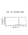
- Figures 3A through 3C respectively illustrate the emission spectra of CRTs emitting green, blue and red light.
- the emission intensity of green light has a primary peak at a wavelength of 550nm, a secondary peak at a wavelength of 490nm and is weak at other wavelengths.
- the emission intensity of blue light peaks at a wavelength of 450nm and falls off within a wavelength range of 400 - 500nm.
- the emission intensity of red light peaks at a wavelength of 620nm.
- the present invention provides a hybrid lens capable of correcting chromatic aberration and a projection optical system using the hybrid lens.
- a hybrid lens according to the present invention is characterised by a spherical lens and a plastic aspherical lens on one face of the spherical lens.
- the hybrid lens has a plastic aspherical lens on the other face of the spherical lens also.
- the spherical lens is glass.
- the refractive index of the spherical lens differs from that of the or each aspherical lens. More preferably, the refractive index of the spherical lens is in the range 1.45 - 1.95 and the or each aspherical lens has a refractive index in the range 1.45 - 1.8.
- an aspherical lens surface z defined by: where c is the surface curvature (an inverse function of radius), is the radial coordinates of an optical surface, k is a conic constant and ⁇ i is a polynominal coefficient defining the deviation from a spherical surface.
- a video projector according to the present invention comprises an optical system including a hybrid lens according to the present invention.
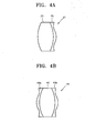
- an aspherical hybrid lens 21 includes a spherical lens 23 and an aspherical lens 25 on one or other of the faces of the spherical lens 23.
- a ratio of the occupied area of the aspherical lens 25 to the gross area depends on the area of illuminating incident light.
- the spherical lens 23 is formed of glass and its refractive index is constant throughout. It is preferable that the refractive index of the glass is within a range of 1.45 - 1.95.
- the aspherical lens 25 is formed of plastic and has a refractive index that is constant throughout the lens and preferably different from the refractive index of the glass spherical lens 22. It is preferable that the refractive index of the plastic is within a range of 1.45 - 1.8.
- a hybrid lens 41 includes a spherical lens 43 and first and second aspherical lenses 45a, 45b on respective faces of the spherical lens 43.
- the spherical lens 43 is formed of glass and has a similar refractive index to the spherical lens 23.
- the first and second aspherical lenses 45a, 46b may be formed as a single lens on the surface of the spherical lens 43 or may be separately formed on the faces of the spherical lens 43.
- the refractive indices of the first and second aspherical lenses 45a, 45b are similar to the refractive index of the aspherical lens 25 shown in Figure 4A.
- the refraction angles of spherical and aspherical lenses vary with wavelength, which results in chromatic aberration.
- the focal length of the spherical lens decreases.
- focal length is shortest for red light and longest for blue light.
- the focal length of the aspherical lens increases.
- focal length is shortest for blue light and longest for red light.
- a hybrid lens according to the present invention' is formed by combining a spherical lens and an aspherical lens so that the chromatic aberration of the two lenses compensate for each other.
- the hybrid lens has no chromatic aberration.
- the refractive indexes and curvatures of the spherical lens and the aspherical lens must be adjusted appropriately to completely remove chromatic aberration in the hybrid lens.
- forming the spherical lens of glass and the aspherical lens of plastic is effective in removing chromatic aberration.
- a protective lens 32, a meniscus lens 36, first and second power lenses 38, 39, and a hybrid lens 31 are sequentially arranged along the same optical axis.
- a cooling liquid 34 is provided between the protective lens 32 and the meniscus lens 36 and a hybrid lens 31 includes first and second aspherical lenses 35a, 36b which are formed on the surfaces of a spherical lens 33.
- the first and second aspherical lenses 35a, 35b can have different refractive indices and dispersions from the spherical lens 33 so as to correct aberration and have constant focusing power.
- the hybrid lens 31 is positioned adjacent to an object surface.
- the meniscus lens 36 or the first and second power lenses 38, 39 can be replaced with hybrid lenses to reduce chromatic aberration. It is preferable that the hybrid lens 31, and the first and second lenses 38, 39 are power correction lenses.
- the first and second lenses 38, 39 have aspherical surfaces so as to compensate effectively for chromatic aberration.
- the protective lens 32 covers the face of a CRT and allows red, green or blue light emitted from the fluorescent surface of the CRT to proceed toward the inside of the projection optical system 30. Light that has passed through the protective lens 32 is refracted by the meniscus lens 36 and diverges after passing through the cooling liquid 34.
- the meniscus lens 36 is a single lens element, both surfaces of which curve in the same direction.
- a convex meniscus lens has a central portion that is thicker than an outer portion.
- a concave meniscus lens has a central portion that is thinner than an outer portion.
- the first and second aspherical lenses 35a, 35b of the hybrid lens 31 can have different refractive indices from the spherical lens 33 so as to serve as power lenses. Since a projection TV uses a monochromatic CRT, RGB colour signals are produced by the phosphors of the red, green, and blue CRTs and combined by the projection optical system 30 to form an image. Green light greatly affects image quality.
- the present invention proposes an aspherical hybrid lens formed by combining an aspherical lens and a spherical lens having different optical characteristics such as different refractive indexes and dispersions so as to correct aberration of each wavelength included in green light.
- the table of Figure 6 shows design values for lenses used in a projection optical system according to the present invention, i.e., radii, thicknesses, refractive indices and numerical apertures.
- Equation 2 is the basic equation for designing the aspherical surfaces 1, 4, 9, 10, and 11.
- c is a surface curvature (an inverse function of a radius)
- ⁇ i is a coefficient of a polynominal expression defining deviation from a spherical surface.
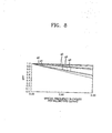
- Figure 8 illustrates the MTF measured using lenses having aspherical surfaces 1, 4, 9, 10 and 11 manufactured according to the set design values in the projection optical system shown in Figure 5.
- Figure 8 is a graph of the MTF of the projection optical system of the present invention versus spatial frequency in cycles per millimetre.
- g0 represents an image height of zero
- g1 represents an image height of 20mm
- g2 represents an image height of 40mm
- g3 represents an image height of 60mm
- g4 represents an image height of 63.5mm.
- the MTF of the projection optical system of the present invention increases in each field compared to that of the projection optical system shown in Figure 2, and is above 0.5 at a spatial frequency of about 5Hz. Accordingly, the projection optical system according to the present invention can realize higher contrast and resolution than a projection optical system according to the prior art.
- a hybrid lens in which an aspherical lens is formed of plastic on the surface of a spherical lens formed of glass, is disposed in a projection optical system.
- chromatic aberration can be reduced so as to provide an image having high contrast and resolution.
Landscapes
- Physics & Mathematics (AREA)
- General Physics & Mathematics (AREA)
- Optics & Photonics (AREA)
- Lenses (AREA)
Abstract
Description
- The present invention relates to a hybrid lens and a video projector.
- Focusing performance is very important in a known projection TV optical system, which projects an image formed on the face of a Braun tube (CRT; Cathode Ray Tube) onto a screen. For focusing, the projection optical system uses an aspherical plastic lens capable of compensating for aberration. However, the refractive index, shape and focal length of the aspherical plastic lens vary with changes in temperature, which degrades the focusing performance. Various techniques for solving this problem are disclosed in WO-A-9834134, US-A-5272540 and US-A-4924244.
- Figure 1 is a cross-sectional view of a projection optical system disclosed in US-A-5309283.
Reference numerals third group lens 13 is composed of a pair ofglass lenses Reference numeral 16 denotes a cooling liquid,reference numeral 17 denotes a protective lens that covers a fluorescent surface P1 of a CRT andreference numeral 19 denotes a screen. Referring to Figure 1, RAY1 denotes an upper limit and RAY2 denotes a lower limit of light rays emitted from a centre point A of the face P1 of the CRT. RAY3 denotes an upper limit and RAY4 denotes a lower limit of light rays emitted from an object point B in the periphery of an image plane. - The first and
second group lenses first group lens 11 is made concave and disposed adjacent to thescreen 19, thesecond group lens 12 is made convex and disposed behind thefirst group lens 11 and the refractive indices of the first andsecond group lenses third group lens 13 is formed by bonding a pair of glass lenses and is disposed immediately behind thesecond group lens 12. - However, it is costly to manufacture groups of lenses in the prior art projection optical system as disclosed in US-A-5272540 and image quality is degraded.
- Figure 2 is a graph of modulation transfer function (MTF) against spatial frequency in cycles per millimeter when a general aspherical lens is used. Here, the MTF is defined by
Equation 1 in terms of the maximum intensity (Max) and the minimum intensity (Min) of light. When the MTF is 1, resolution is optimal. Resolution decreases with a reduction in the MTF. - Referring to Figure 2, f0 represents the case where an image height h (which refers to the distance from a point "O", where the optical axis meets the image plane, to an image) is zero, f1 represents the case where the image height h is 20mm, f2 represents the case where the image height h is 40mm, f2 represents the case where the image height h is 60mm and f4 represents the case the image height h is 63.50mm. Regardless of the variation in the spatial frequency, the MTF is the highest when the image height h is zero (f0) and the lowest when the image height h is 40mm (f2). However, as can be seen from f0, f1, f2, f3 and f4, the MTF sharply decreases with increasing spatial frequency. As the MTF decreases, the contrast of an image formed by the projection optical system reduces.
- Figures 3A through 3C respectively illustrate the emission spectra of CRTs emitting green, blue and red light. Referring to Figure 3A, the emission intensity of green light has a primary peak at a wavelength of 550nm, a secondary peak at a wavelength of 490nm and is weak at other wavelengths. Referring to Figure 3B, the emission intensity of blue light peaks at a wavelength of 450nm and falls off within a wavelength range of 400 - 500nm. Referring to Figure 3C, the emission intensity of red light peaks at a wavelength of 620nm. Since the emission spectra of blue and red light overlap green light emission spectrum, the wavelengths of blue and red light, except the central wavelength of green light, are emitted in different wavelength bands, which results in chromatic aberration. Thus, an optical system capable of reducing the chromatic aberration is required.
- The present invention provides a hybrid lens capable of correcting chromatic aberration and a projection optical system using the hybrid lens.
- A hybrid lens according to the present invention is characterised by a spherical lens and a plastic aspherical lens on one face of the spherical lens.
- Preferably, the hybrid lens has a plastic aspherical lens on the other face of the spherical lens also.
- Preferably, the spherical lens is glass.
- Preferably, the refractive index of the spherical lens differs from that of the or each aspherical lens. More preferably, the refractive index of the spherical lens is in the range 1.45 - 1.95 and the or each aspherical lens has a refractive index in the range 1.45 - 1.8.
- Preferably, having an aspherical lens surface z defined by:where c is the surface curvature (an inverse function of radius),
 is the radial coordinates of an optical surface, k is a conic constant and α i is a polynominal coefficient defining the deviation from a spherical surface.
- A video projector according to the present invention comprises an optical system including a hybrid lens according to the present invention.
- Embodiments of the present invention will now be described, by way of example, with reference to Figures 4A to 8 of the accompanying drawings, in which:-
- Figure 1 is a cross-sectional view of a projection optical system disclosed in US-A-5272540;
- Figure 2 is a graph of a modulation transfer function (MTF) versus spatial frequency in cycles per millimetre when a conventional aspherical plastic lens is used.
- Figures 3A through 3C respectively illustrate the emission spectra of a CRT emitting green, blue and red light;
- Figure 4A is a schematic cross-sectional view of an aspherical hybrid lens according to the present invention;
- Figure 4B is a schematic cross-sectional view of another hybrid lens according to the present invention;
- Figure 5 is a schematic cross-sectional view of a projection optical system according to the present invention;
- Figure 6 is a table of the radii, thicknesses, refractive indices and numerical apertures of lenses used in the projection optical system shown in Figure 5;
- Figure 7 is a table of aspherical coefficients used in the projection optical system shown in Figure 5; and
- Figure 8 is a graph of the MTF of the projection optical system of Figure 5 versus spatial frequency in cycles per millimetre.
-
- In the drawings, the thicknesses and sizes of lenses are exaggerated for clarity. Also, spherical and aspherical shapes of the lenses are to be taken as examples only.
- Referring to Figure 4A, an
aspherical hybrid lens 21 includes aspherical lens 23 and anaspherical lens 25 on one or other of the faces of thespherical lens 23. A ratio of the occupied area of theaspherical lens 25 to the gross area depends on the area of illuminating incident light. - The
spherical lens 23 is formed of glass and its refractive index is constant throughout. It is preferable that the refractive index of the glass is within a range of 1.45 - 1.95. Theaspherical lens 25 is formed of plastic and has a refractive index that is constant throughout the lens and preferably different from the refractive index of the glass spherical lens 22. It is preferable that the refractive index of the plastic is within a range of 1.45 - 1.8. - Referring to Figure 4B, a
hybrid lens 41 includes aspherical lens 43 and first and secondaspherical lenses spherical lens 43. - Like the
spherical lens 23 shown in Figure 4A, thespherical lens 43 is formed of glass and has a similar refractive index to thespherical lens 23. The first and secondaspherical lenses 45a, 46b may be formed as a single lens on the surface of thespherical lens 43 or may be separately formed on the faces of thespherical lens 43. The refractive indices of the first and secondaspherical lenses aspherical lens 25 shown in Figure 4A. - The refraction angles of spherical and aspherical lenses vary with wavelength, which results in chromatic aberration. As the wavelength of light passing through a spherical lens increases, the focal length of the spherical lens decreases. Thus, focal length is shortest for red light and longest for blue light. In contrast, as the wavelength of light passing through an aspherical lens increases, the focal length of the aspherical lens increases. Thus, focal length is shortest for blue light and longest for red light. A hybrid lens according to the present invention'is formed by combining a spherical lens and an aspherical lens so that the chromatic aberration of the two lenses compensate for each other. Thus, the hybrid lens has no chromatic aberration. Here, the refractive indexes and curvatures of the spherical lens and the aspherical lens must be adjusted appropriately to completely remove chromatic aberration in the hybrid lens. In particular, forming the spherical lens of glass and the aspherical lens of plastic is effective in removing chromatic aberration.
- Referring to Figure 5, in a projection
optical system 30, aprotective lens 32, ameniscus lens 36, first andsecond power lenses hybrid lens 31 are sequentially arranged along the same optical axis. A coolingliquid 34 is provided between theprotective lens 32 and themeniscus lens 36 and ahybrid lens 31 includes first and secondaspherical lenses 35a, 36b which are formed on the surfaces of aspherical lens 33. The first and secondaspherical lenses spherical lens 33 so as to correct aberration and have constant focusing power. - In the projection
optical system 30, thehybrid lens 31 is positioned adjacent to an object surface. However, themeniscus lens 36 or the first andsecond power lenses hybrid lens 31, and the first andsecond lenses second lenses - The functions of the lenses, except the
hybrid lens 31, and optical paths of light passing through the lenses will now be explained. - The
protective lens 32 covers the face of a CRT and allows red, green or blue light emitted from the fluorescent surface of the CRT to proceed toward the inside of the projectionoptical system 30. Light that has passed through theprotective lens 32 is refracted by themeniscus lens 36 and diverges after passing through the coolingliquid 34. - The
meniscus lens 36 is a single lens element, both surfaces of which curve in the same direction. A convex meniscus lens has a central portion that is thicker than an outer portion. A concave meniscus lens has a central portion that is thinner than an outer portion. The light that has diverged after passing through themeniscus lens 36 is refracted by the first andsecond power lenses hybrid lens 31. In this optical system, the light emitted from the bottom portion of theprotective lens 32 proceeds toward the top portion of thehybrid lens 31. - The first and second
aspherical lenses hybrid lens 31 can have different refractive indices from thespherical lens 33 so as to serve as power lenses. Since a projection TV uses a monochromatic CRT, RGB colour signals are produced by the phosphors of the red, green, and blue CRTs and combined by the projectionoptical system 30 to form an image. Green light greatly affects image quality. Thus, the present invention proposes an aspherical hybrid lens formed by combining an aspherical lens and a spherical lens having different optical characteristics such as different refractive indexes and dispersions so as to correct aberration of each wavelength included in green light. - The table of Figure 6 shows design values for lenses used in a projection optical system according to the present invention, i.e., radii, thicknesses, refractive indices and numerical apertures.
- Referring to Figure 6,
reference numerals reference numerals reference numerals 5 and 8 denote aperture stop for removing unnecessary light.Equation 2 described above is the basic equation for designing theaspherical surfaces where, c is a surface curvature (an inverse function of a radius), is the position on the optical surface in radial coordinates, k is a conic constant (k=0 in the current optical design), and α i is a coefficient of a polynominal expression defining deviation from a spherical surface.
- The table of Figure 7 shows the polynominal coefficient α i (i= 2 - 7) of the
aspherical surfaces aspherical surfaces - Figure 8 is a graph of the MTF of the projection optical system of the present invention versus spatial frequency in cycles per millimetre. Here, g0 represents an image height of zero, g1 represents an image height of 20mm, g2 represents an image height of 40mm, g3 represents an image height of 60mm, and g4 represents an image height of 63.5mm. As can be seen in Figure 8, the MTF of the projection optical system of the present invention increases in each field compared to that of the projection optical system shown in Figure 2, and is above 0.5 at a spatial frequency of about 5Hz. Accordingly, the projection optical system according to the present invention can realize higher contrast and resolution than a projection optical system according to the prior art.
- As described above, in the present invention, a hybrid lens, in which an aspherical lens is formed of plastic on the surface of a spherical lens formed of glass, is disposed in a projection optical system. Thus, chromatic aberration can be reduced so as to provide an image having high contrast and resolution.
- While the present invention has been particularly shown and described with reference to exemplary embodiments thereof, it will be understood by those of ordinary skill in the art that various changes in form and details may be made.
Claims (27)
- A hybrid lens characterised by a spherical lens (23; 43; 33) and a plastic aspherical lens (21; 45a; 35a) on one face of the spherical lens.
- A hybrid lens according to claim 1, having a plastic aspherical lens (45b; 35b) on the other face of the spherical lens (43; 33),
- A hybrid lens according to claim 1 or 2, wherein the spherical lens (23; 43; 33) is glass.
- A hybrid lens according to claim 1, 2 or 3, wherein the refractive index of the spherical lens (23; 43; 33) differs from that of the or each aspherical lens (21; 45a, 45b; 35a, 35b).
- A hybrid lens according to claim 4, wherein the refractive index of the spherical lens (23; 43; 33) is in the range 1.45 - 1.95 and the or each aspherical lens (21; 45a, 45b; 35a, 35b) has a refractive index in the range 1.45 - 1.8.
- A hybrid lens according to any preceding claim, wherein having an aspherical lens surface z defined by:where c is the surface curvature (an inverse function of radius),
 is the radial coordinates of an optical surface, k is a conic constant and αi is a polynominal coefficient defining the deviation from a spherical surface.
- A video projector comprising an optical system (30) including a hybrid lens (33) according to any preceding claim.
- A hybrid lens comprising:a spherical lens; andan aspherical lens formed of plastic on at least one surface of the spherical lens.
- The hybrid lens of claim 8, wherein the aspherical lens is formed on an incidence surface and an emission surface of the spherical lens.
- The hybrid lens of claim 8, wherein the spherical lens is formed of glass.
- The hybrid lens of claim 8, wherein the spherical lens has a refractive index within a range of 1.45 - 1.95.
- The hybrid lens of claim 8, wherein the aspherical lens has a refractive index within a range of 1.45 - 1.8.
- The hybrid lens of claim 8, wherein the spherical lens and the aspherical lens have different refractive indexes.
- The hybrid lens of claim 8, wherein when c is a surface curvature (an inverse function of radius),is radial coordinates on an optical surface, k is a conic constant, and αi is a polynominal coefficient defining the deviation from a spherical surface, a lens surface z of the aspherical lens satisfies the equation below:


- A projection optical system comprising a hybrid lens that is positioned along an optical path between a fluorescent surface and a screen onto which light emitted from the fluorescent surface is projected to form an image and includes a spherical lens and an aspherical lens formed of plastic on at least one surface of the spherical lens.
- The projection optical system of claim 15, wherein the aspherical lens is formed on an incidence surface and an emission surface of the spherical lens.
- The projection optical system of claim 15, wherein the spherical lens is formed of glass.
- The projection optical system of claim 16, wherein the spherical lens has a refractive index within a range of 1.45 - 1.95.
- The projection optical system of claim 15, wherein the aspherical lens has a refractive index within a range of 1.45 - 1.8.
- The projection optical system of claim 15, wherein the spherical lens and the aspherical lens have different refractive indexes.
- The projection optical system of claim 15, wherein when c is a surface curvature (an inverse function of radius),is radial coordinates on an optical surface, k is a conic constant, and αi is a polynominal coefficient defining the deviation from a spherical surface, a lens surface z of the aspherical lens satisfies the equation below:


- The projection optical system of claim 15, further comprising a protective lens that covers the entire fluorescent surface.
- The projection optical system of claim 22, further comprising a meniscus lens that is positioned along an optical path between the protective lens and the hybrid lens.
- The projection optical system of claim 23, further comprising a cooling liquid that is positioned between the protective lens and the meniscus lens.
- The projection optical system of claim 15, wherein the hybrid lens is a correction power lens.
- The projection optical system of claim 15, further comprising at least one correction power lens that is positioned between the hybrid lens and the fluorescent surface, and refracts incident light.
- The projection optical system of claim 25, wherein the correction power lens has an aspherical surface.
Applications Claiming Priority (2)
| Application Number | Priority Date | Filing Date | Title |
|---|---|---|---|
| RU2002124710/28A RU2227314C1 (en) | 2002-09-17 | 2002-09-17 | Optical system of projection tv receiver |
| RU2002124710 | 2002-09-17 |
Publications (1)
| Publication Number | Publication Date |
|---|---|
| EP1400827A1 true EP1400827A1 (en) | 2004-03-24 |
Family
ID=31944965
Family Applications (1)
| Application Number | Title | Priority Date | Filing Date |
|---|---|---|---|
| EP03254158A Ceased EP1400827A1 (en) | 2002-09-17 | 2003-06-30 | Aspherical lens and video projector |
Country Status (6)
| Country | Link |
|---|---|
| US (1) | US6992837B2 (en) |
| EP (1) | EP1400827A1 (en) |
| JP (1) | JP2004110023A (en) |
| KR (1) | KR100529312B1 (en) |
| CN (1) | CN1484059A (en) |
| RU (1) | RU2227314C1 (en) |
Families Citing this family (10)
| Publication number | Priority date | Publication date | Assignee | Title |
|---|---|---|---|---|
| JP2005331530A (en) * | 2004-05-18 | 2005-12-02 | Hitachi Ltd | Projection lens device and rear projection image display device using the same |
| JP2006178077A (en) * | 2004-12-21 | 2006-07-06 | Sony Corp | Zoom lens and imaging device |
| RU2326418C2 (en) * | 2005-04-19 | 2008-06-10 | Самсунг Электроникс Ко., Лтд. | Projection optic system of home theater objective with internal compensation of projective screen distortions |
| CN101266307B (en) * | 2007-03-14 | 2011-03-23 | 鸿富锦精密工业(深圳)有限公司 | Combined plastic lens and its manufacture method |
| KR100916502B1 (en) * | 2007-08-10 | 2009-09-08 | 삼성전기주식회사 | Ultra compact imaging optics |
| WO2011038457A1 (en) * | 2009-09-30 | 2011-04-07 | Lions Eye Institute Limited | Imager, module for an imager, imaging system and method |
| CN103293642B (en) * | 2012-03-02 | 2015-08-26 | 扬明光学股份有限公司 | Projection lens and projection device |
| WO2015180647A1 (en) | 2014-05-27 | 2015-12-03 | Mediatek Inc. | Projection processor for projective display system |
| US9804367B2 (en) * | 2015-11-04 | 2017-10-31 | Omnivision Technologies, Inc. | Wafer-level hybrid compound lens and method for fabricating same |
| CN109358425A (en) * | 2018-11-02 | 2019-02-19 | 杭州有人光电技术有限公司 | A kind of full HD eyepiece optical system of virtual reality device |
Citations (7)
| Publication number | Priority date | Publication date | Assignee | Title |
|---|---|---|---|---|
| US5272540A (en) * | 1989-04-28 | 1993-12-21 | Hitachi, Ltd. | Temperature compensating lens system for projection television |
| US5309283A (en) * | 1993-03-30 | 1994-05-03 | U.S. Precision Lens Incorporated | Hybrid, color-corrected, projection TV lens system |
| JPH0886904A (en) * | 1994-09-16 | 1996-04-02 | Asahi Optical Co Ltd | Compound aspherical lens mold tool |
| US5786942A (en) * | 1995-10-03 | 1998-07-28 | Asahi Kogaku Kogyo Kabushiki Kaisha | Zoom lens and aspherical lens |
| US5828498A (en) * | 1994-10-25 | 1998-10-27 | Asahi Kogaku Kogyo Kabushiki Kaisha | Objective lens of endoscope |
| US6297860B1 (en) * | 1996-04-29 | 2001-10-02 | Corning Precision Lens | Partial color-corrected projection lens system |
| US20010033360A1 (en) * | 2000-04-20 | 2001-10-25 | Hiroshi Koizumi | Hybrid lens and method for forming the same |
Family Cites Families (14)
| Publication number | Priority date | Publication date | Assignee | Title |
|---|---|---|---|---|
| US527540A (en) * | 1894-10-16 | Railway-train protecting device | ||
| NL8500453A (en) * | 1985-02-18 | 1986-09-16 | Philips Nv | PROJECTIVE SYSTEM. |
| JPS61203401A (en) * | 1985-03-05 | 1986-09-09 | Mitsubishi Electric Corp | Integral hybrid lens and apparatus for producing said lens |
| JPS6425113A (en) * | 1987-07-21 | 1989-01-27 | Mark Kk | Finite system large aperture single lens |
| JPH0679105B2 (en) * | 1987-12-21 | 1994-10-05 | 株式会社日立製作所 | Lens for projection television |
| JP2934458B2 (en) * | 1989-09-08 | 1999-08-16 | 株式会社日立製作所 | Projection lens device and projection type image display device using the same |
| JP2727373B2 (en) * | 1990-09-18 | 1998-03-11 | 株式会社マーク | Finite system large aperture imaging lens |
| JP3328001B2 (en) * | 1993-06-15 | 2002-09-24 | オリンパス光学工業株式会社 | Zoom lens |
| RU2065192C1 (en) * | 1993-08-27 | 1996-08-10 | Акционерное общество открытого типа "Красногорский завод им.С.А.Зверева" | Single-lens objective with gradient layer |
| JP3455309B2 (en) * | 1994-11-17 | 2003-10-14 | ペンタックス株式会社 | Objective lens for endoscope |
| JPH09159916A (en) * | 1995-10-03 | 1997-06-20 | Asahi Optical Co Ltd | Zoom lens |
| CN2280923Y (en) | 1996-09-13 | 1998-05-06 | 宁小旭 | Electronic imaging sensor lens |
| US5991089A (en) * | 1997-01-31 | 1999-11-23 | U.S. Precision Lens Inc. | Long focal length projection lenses for use with large pixelized panels |
| JP4689805B2 (en) | 2000-09-28 | 2011-05-25 | 富士フイルム株式会社 | Optical scanning device |
-
2002
- 2002-09-17 RU RU2002124710/28A patent/RU2227314C1/en not_active IP Right Cessation
-
2003
- 2003-02-05 KR KR10-2003-0007116A patent/KR100529312B1/en not_active Expired - Fee Related
- 2003-06-26 CN CNA031487866A patent/CN1484059A/en active Pending
- 2003-06-30 EP EP03254158A patent/EP1400827A1/en not_active Ceased
- 2003-09-10 JP JP2003317904A patent/JP2004110023A/en active Pending
- 2003-09-17 US US10/664,043 patent/US6992837B2/en not_active Expired - Fee Related
Patent Citations (7)
| Publication number | Priority date | Publication date | Assignee | Title |
|---|---|---|---|---|
| US5272540A (en) * | 1989-04-28 | 1993-12-21 | Hitachi, Ltd. | Temperature compensating lens system for projection television |
| US5309283A (en) * | 1993-03-30 | 1994-05-03 | U.S. Precision Lens Incorporated | Hybrid, color-corrected, projection TV lens system |
| JPH0886904A (en) * | 1994-09-16 | 1996-04-02 | Asahi Optical Co Ltd | Compound aspherical lens mold tool |
| US5828498A (en) * | 1994-10-25 | 1998-10-27 | Asahi Kogaku Kogyo Kabushiki Kaisha | Objective lens of endoscope |
| US5786942A (en) * | 1995-10-03 | 1998-07-28 | Asahi Kogaku Kogyo Kabushiki Kaisha | Zoom lens and aspherical lens |
| US6297860B1 (en) * | 1996-04-29 | 2001-10-02 | Corning Precision Lens | Partial color-corrected projection lens system |
| US20010033360A1 (en) * | 2000-04-20 | 2001-10-25 | Hiroshi Koizumi | Hybrid lens and method for forming the same |
Non-Patent Citations (1)
| Title |
|---|
| PATENT ABSTRACTS OF JAPAN vol. 1996, no. 08 30 August 1996 (1996-08-30) * |
Also Published As
| Publication number | Publication date |
|---|---|
| RU2227314C1 (en) | 2004-04-20 |
| KR100529312B1 (en) | 2005-11-17 |
| US6992837B2 (en) | 2006-01-31 |
| JP2004110023A (en) | 2004-04-08 |
| US20040114057A1 (en) | 2004-06-17 |
| CN1484059A (en) | 2004-03-24 |
| KR20040025519A (en) | 2004-03-24 |
Similar Documents
| Publication | Publication Date | Title |
|---|---|---|
| US4963007A (en) | Color corrected projection lens | |
| JP2954217B2 (en) | Projection lens | |
| US5168351A (en) | Short focal length video color projector employing dichroic mirror block | |
| EP1400827A1 (en) | Aspherical lens and video projector | |
| US20190204542A1 (en) | Optical lens | |
| KR20240125983A (en) | Optical focusing lens | |
| US8736985B2 (en) | Photographic lens optical system | |
| EP0188016B1 (en) | Projection lens system | |
| JP2024501607A (en) | Optical systems and head-mounted displays | |
| KR960013312B1 (en) | Image projection system | |
| CN117666090A (en) | Angle-enlarging lens | |
| CN116107058B (en) | A large-aperture optical system for ultra-low illumination | |
| US20130162957A1 (en) | Projection apparatus and projection lens thereof | |
| RU2348953C1 (en) | Infrared rapid three-lens objective | |
| KR0138743B1 (en) | Projection lenses for rear type projection television | |
| US5386315A (en) | IR fast low light level lens system | |
| EP1075150A2 (en) | Projection lens system | |
| KR900002622B1 (en) | Optical system for projection tv | |
| EP0745228B1 (en) | Dual grooved fresnel lens for overhead projection | |
| JPS62278520A (en) | Optical device for projection type television | |
| JPH0814653B2 (en) | Projection lens | |
| CN115016214B (en) | Projector with a light source for projecting light | |
| CN114114614B (en) | Short-focus projection optical system | |
| KR20050093755A (en) | Hybrid lens and projection optical system comprising the same | |
| CN116299987A (en) | Optical lens |
Legal Events
| Date | Code | Title | Description |
|---|---|---|---|
| PUAI | Public reference made under article 153(3) epc to a published international application that has entered the european phase |
Free format text: ORIGINAL CODE: 0009012 |
|
| AK | Designated contracting states |
Kind code of ref document: A1 Designated state(s): AT BE BG CH CY CZ DE DK EE ES FI FR GB GR HU IE IT LI LU MC NL PT RO SE SI SK TR |
|
| AX | Request for extension of the european patent |
Extension state: AL LT LV MK |
|
| RAP1 | Party data changed (applicant data changed or rights of an application transferred) |
Owner name: SAMSUNG ELECTRONICS CO., LTD. |
|
| 17P | Request for examination filed |
Effective date: 20040923 |
|
| AKX | Designation fees paid |
Designated state(s): DE FR GB NL |
|
| 17Q | First examination report despatched |
Effective date: 20041118 |
|
| STAA | Information on the status of an ep patent application or granted ep patent |
Free format text: STATUS: THE APPLICATION HAS BEEN REFUSED |
|
| 18R | Application refused |
Effective date: 20071126 |