FIELD OF THE INVENTION
The present invention is generally related towards the field
of converting hydrocarbon gas to liquid hydrocarbons. In
particular, the present invention provides a new and improved
method and apparatus for preparing the liquid hydrocarbons from
synthesis gas. More particularly, the present invention provides
a method for the regeneration of deactivated hydrocarbon
synthesis catalysts.
BACKGROUND OF THE INVENTION
Large quantities of methane, the main component of natural
gas, are available in many areas of the world, and natural gas is
predicted to outlast oil reserves by a significant margin.
However, most natural gas is situated in areas that are
geographically remote from population and industrial centers.
The costs of compression, transportation, and storage make its
use economically unattractive. To improve the economics of
natural gas use, much research has focused on the use of methane
as a starting material for the production of higher hydrocarbons
and hydrocarbon liquids, which are more easily transported and
thus more economical. The conversion of methane to hydrocarbons
is typically carried out in two steps. In the first step,
methane is converted into a mixture of carbon monoxide and
hydrogen (i.e., synthesis gas or syngas). In a second step, the
syngas is converted into hydrocarbons.
This second step, the preparation of hydrocarbons from
synthesis gas, is well known in the art and is usually referred
to as Fischer-Tropsch synthesis, the Fischer-Tropsch process, or
Fischer-Tropsch reaction(s). Fischer-Tropsch synthesis generally
entails contacting a stream of synthesis gas with a catalyst
under temperature and pressure conditions that allow the
synthesis gas to react and form hydrocarbons.
More specifically, the Fischer-Tropsch reaction is the
catalytic hydrogenation of carbon monoxide to produce any of a
variety of products ranging from methane to higher alkanes and
aliphatic alcohols. It is the catalytic nature of the Fischer-Tropsch
reaction that makes the process economically feasible.
Catalysts desirably have the function of increasing the rate of a
reaction without being consumed by the reaction. Common catalysts
for use in the Fischer-Tropsch process contain at least one metal
from Groups 8, 9, or 10 of the Periodic Table (in the new IUPAC
notation, which is used throughout the present specification).
Catalyst systems often employ a promoter in conjunction with
the principal catalytic metal. A promoter typically improves one
or more measures of the performance of a catalyst, such as,
activity, stability, selectivity, reducibility, or
regenerability. For example, ruthenium, rhenium, and platinum
are known to increase the reducibility of cobalt.
Further, in addition to the catalytic metal, a Fischer-Tropsch
catalyst often includes a support material. The support
is typically a porous carrier that provides mechanical strength
and a high surface area in which the catalytic metal and any
promoter(s) may be deposited. Catalyst supports for catalysts
used in Fischer-Tropsch synthesis of hydrocarbons have typically
been refractory oxides (e.g., silica, alumina, titania, zirconia
or mixtures thereof).
After a period of time in operation, a catalyst may become
deactivated, losing its effectiveness for catalyzing the desired
reaction to a degree that makes the process uneconomical at best
and inoperative at worst. The more deactivated a particular
catalyst is, the less efficient the catalyst is at enhancing the
rate of the desired reaction. At this point, the catalyst can be
either replaced or regenerated. Replacement of catalyst could be
quite expensive due to the loss of expensive metals and cost of
making a replacement catalyst. For these reasons, regeneration
is preferred over replacement.
Traditionally, regeneration methods for Fischer-Tropsch
catalysts have used operating conditions similar to the Fischer-Tropsch
operating conditions. However, this approach limits the
scope of catalysts that can be effectively regenerated to those
for which regeneration at operating conditions is possible, such
as those deactivated by ammonia or hydrogen cyanide poisoning or
to some extent, surface condensation of heavy wax products.
Hence, there is still a great need to identify new
regeneration methods, particularly methods that can effectively
regenerate Fischer-Tropsch catalysts without having to replace
the catalysts and without significant downtime or loss of
production. Also, there is a need for regeneration methods that
can regenerate Fischer-Tropsch catalysts that have been
deactivated by a variety of deactivation mechanisms.
SUMMARY OF THE INVENTION
The present invention relates generally to the regeneration
of hydrocarbon synthesis catalysts. In particular, the present
invention is directed toward the regeneration of deactivated
Fischer-Tropsch type catalysts using a dry hydrogen rich gas.
The regeneration of the Fischer-Tropsch catalysts is accomplished
by contacting the deactivated catalyst material with the dry
hydrogen rich gas at elevated temperature and relatively low
pressure, i.e., conditions that are generally different than
those of the Fischer-Tropsch operating conditions. Several
embodiments are preferred, including both methods and apparatus
for carrying out the present invention.
In general, the preferred method comprises locating the
catalyst material in a vessel, such as a hydrocarbon synthesis
reactor or any vessel capable of enduring the regeneration
process, preparing the deactivated catalyst by removing all or
substantially all of the water present in the catalyst slurry,
and contacting the deactivated catalyst material with a hydrogen
rich gas under the appropriate conditions. In addition, it is
preferred that the concentration of the solids remain relatively
stable throughout the process. Thus, additional liquid,
preferably heavy hydrocarbons, may be added to maintain the
solids concentration.
The regeneration vessel is comprised preferably of any
vessel capable of withstanding the temperature and pressures of
the regeneration process. The capacity of the regeneration
vessel will depend on the plant design and potential frequency of
use of the vessel. In addition, the vessel size and capacity may
vary depending upon the use of a storage or blending tank as an
intermediate vessel between the synthesis reactor and
regeneration vessel.
The operating conditions for the overall process are
generally different than a Fischer-Tropsch process. The
preferred temperature for the water removal process is greater
than about 210°C, with a preferred pressure of greater than about
50 psia but preferably equal to or lower than the Fischer-Tropsch
reactor operating pressure. Likewise, the regeneration reaction
is preferably carried out at temperatures in excess of about 220°C
and pressures greater than 50 psia. The duration of the
regeneration processes can be from about 0.5 to about 48 hours.
These and other embodiments, features and advantages of the
present invention will become apparent with reference to the
following detailed description and drawings.
BRIEF DESCRIPTION OF THE DRAWINGS
For a more detailed understanding of the present invention,
reference is made to the accompanying Figures, wherein:
DETAILED DESCRIPTION OF THE PREFERRED EMBODIMENTS
There are shown in the Figures and drawings, and herein will
be described in detail, specific embodiments of the present
invention with the understanding that the present disclosure is
to be considered an exemplification of the principles of the
invention, and is not intended to limit the invention to that
illustrated and described herein. The present invention is
susceptible to embodiments of different forms or order and should
not be interpreted to be limited to the particular structures or
compositions contained herein. In particular, various
embodiments of the present invention provide a number of
different configurations of the overall gas to liquid conversion
process.
The present invention is directed toward an improved method
for regenerating Fischer-Tropsch catalysts. The regeneration
process involves the stripping off of water, dissolved gases and
small, trapped bubbles containing various gases such as water,
CO, light hydrocarbons, etc. from the catalyst slurry that can
form during the Fischer-Tropsch reaction. After stripping, the
catalyst is contacted with a hydrogen rich gas that reduces
and/or reactivates the catalyst material. Regeneration of
Fischer-Tropsch catalysts in accordance with the present
invention can recapture a significant amount, if not all, of the
lost catalyst activity of the deactivated catalyst material.
It has been discovered that the regeneration process is
enhanced due to a pretreatment of the slurry in which a "dry"
gas is introduced into the vessel. It is believed that the
stripping step has two primary functions. One is to remove all
or substantially all of the water that may be dissolved in the
slurry mixture, i.e., water dissolved in the Fischer-Tropsch
waxes, and also remove adsorbed water from the surface of the
catalyst material. Another function of the stripping step is to
remove dissolved gases and small entrained bubbles within the
slurry. After stripping, the deactivated catalyst slurry should
comprise less than 10 mole % water, preferably less than 5 mole %
and still more preferably less than 1 mole %. Thus, the
stripping gas should also comprise less than 10 mole % water,
preferably less than 5 mole % and still more preferably less than
1 mole %.
One advantage of the present invention is that the method
allows simultaneously treatment and/or regeneration of Fischer-Tropsch
catalysts that have been deactivated by one or more of a
variety of mechanisms, including but not limited to oxidation of
catalytically active material, poisoning and surface condensation
of heavy Fischer-Tropsch waxes. Further, the present invention
naturally provides an improved method for Fischer-Tropsch
production and ultimately an improved method for the conversion
of hydrocarbon gas to liquids. The preferred embodiments for all
of the present invention's methods as well as a preferred
embodiment for a regeneration apparatus are described herein.
Figure 1 is a schematic diagram of a preferred embodiment of
the present invention. The schematic includes only those
elements relevant to the preferred embodiment, thus, other
elements may be present without departing from the spirit of the
invention. According to this embodiment, a reactor system 100
comprises a synthesis reactor 110 and a regeneration vessel 120.
A flow line 115 connects synthesis reactor 110 and regeneration
vessel 120 such that deactivated catalyst material, preferably
catalyst containing slurry, can be transferred back and forth
between the two vessels. Regeneration vessel 120 also comprises
several other means for introducing or removing gases and/or
liquids. For example, line 125 is a means for introducing a
stripping gas, line 130 is a means for introducing a regeneration
gas, line 135 is a means for introducing an additional liquid and
line 140 is a means for removing gases.
A portion of the deactivated catalyst within synthesis
reactor 110, i.e., such as a Fischer-Tropsch, methanol and higher
alcohols, type reactor, is removed via line 115 as a slurry and
introduced into regeneration vessel 120, such as a second
synthesis reactor or any vessel capable of enduring the
regeneration process. A dry gas is introduced via line 125 into
regeneration vessel 120 to prepare or treat the deactivated
catalyst slurry. The dry gas helps strip the catalyst slurry of
water and entrapped gas bubbles and to remove water adsorbed on
the surface of the catalyst material. The deactivated catalyst
slurry is contacted with a hydrogen rich gas, introduced via line
130, under conditions effective to regenerate or enhance the
activity of the catalyst material. In addition, it is preferred
that the catalyst solid concentration in the slurry remain stable
throughout the process. The slurry will have a tendency to
become more concentrated because light liquids will volatilize or
otherwise escape during stripping and/or hydrogen treatment.
Thus, additional liquid, preferably heavy hydrocarbons, may be
added via line 135 to maintain the solids concentration of the
slurry.
In the most preferred embodiment, the synthesis reactor will
comprise a Fischer-Tropsch reactor. Any Fischer-Tropsch
technology and/or methods known in the art will suffice, however,
a multiphase slurry bubble reactor is preferred. The Fischer-Tropsch
feedstock is hydrogen and carbon monoxide, i.e., syngas.
The hydrogen to carbon monoxide molar ratio is generally
deliberately adjusted to a desired ratio of approximately 2:1,
but can vary between 0.5 and 4. The syngas is contacted with the
Fischer-Tropsch catalyst as it bubbles through the slurry.
Fischer-Tropsch catalysts are well known in the art and generally
comprise a catalytically active metal, a promoter and a support
structure. The most common catalytic metals are Group 8, 9 and
10 of the periodic table metals, such as cobalt, nickel,
ruthenium, and iron or mixtures thereof. The support is
generally alumina, silica, titania, zirconia or mixtures thereof.
As the syngas feedstock contacts the catalyst, the hydrocarbon
synthesis reaction takes place. Over time the Fischer-Tropsch
catalyst material can become deactivated or lose its ability to
enhance reaction rates.
The transfer of the deactivated catalyst from the synthesis
reactor 110 may be accomplished in any way known in the art.
Transfer mechanisms are not critical to the present invention.
For example, the slurry may be transferred by establishing a
pressure differential between the vessels, by pumping or by
gravity. It is preferred that the slurry not significantly drop
in temperature during the transfer because adding heat later
would require additional costs to the system. However, the
transfer temperature is not critical to the effectiveness of the
present invention. For example, even a cooled and solidified
slurry mixture could be physically transferred to a regeneration
vessel and then re-liquefied for processing.
As stated above, the deactivated catalyst slurry is
transferred into regeneration vessel 120. Regeneration vessel
120 can be a vacant, secondary or backup hydrocarbon synthesis
reactor or any vessel capable of enduring the temperature and
pressure conditions of the regeneration process and capable of
treating the desired capacity of the slurry inventory. Several
preferred vessel capacities are herein disclosed, however, the
capacity of the vessel will ultimately depend upon the desired
function, potential use and/or overall size of the plant. For
example, there may be a plurality of Fischer-Tropsch reactors in
a plant design that require catalyst regeneration. The design
may provide that each Fischer-Tropsch reactor have a separate
regeneration vessel and thus, only a 1 to about 25 % capacity of
the reactor inventory may be preferred. Alternatively, it is
also possible that multiple Fischer-Tropsch reactors may feed
into a single regeneration vessel and, thus, a larger capacity of
up to 100% of a single reactor inventory may be preferred. The
exact percentages are not critical. They are intended only as an
illustration that certain designs can use multiple smaller
vessels that may ultimately be more cost effective than a single
larger vessel. In a preferred embodiment, vessel 120 may also be
equipped with a heating or cooling means (not shown), such as
internal or external coils where a heating or cooling medium may
be circulated.
The stripping gas may be any gas that satisfies the desired
limitation on water content. For example, the gas may be any
available gas from existing processes at the plant. Suitable
stripping gases include but are not limited to methane rich gas,
nitrogen, hydrogen rich gas, hydroprocessing tail gas, hydrogen
rich gas from olefin production, or any combination of sources.
In addition, the stripping gas may come from an outside source
such as bottled gases prepared off-site.
Another consideration for the stripping gas is that it
should not significantly react with the slurry or catalyst
material within the slurry to form new products. It should be
appreciated however that some reaction is contemplated and
expected. For example, a small amount of syngas may be present
in the gas to help increase the temperature of the slurry vessel
and contents. The syngas will react due to the catalyst present
to form additional Fischer-Tropsch products. Because of the
reaction's exothermic nature, additional heat will be added to
the system. Significant reaction is preferably avoided, however,
because new water may be formed as a by-product, which would be
counterproductive to the stripping process. Thus, the stripping
process must be able to overcome any additional water being
produced in any reactions between the stripping gas selected and
the slurry or catalyst material.
The stripping process is preferably carried out at operating
conditions close to the synthesis reactor operating conditions.
For example, a stripping process of a catalyst slurry from a
Fischer-Tropsch reactor should be operated from about 200°C to
about 350°C, preferably from about 210°C to about 250°C. It is
preferred that the operating pressures of the stripping process
be equal to or lower than the operating pressure in the preceding
synthesis or Fischer-Tropsch reactor, more preferably 20 psia
lower than the synthesis or Fischer-Tropsch reactor. The process
can be carried out at pressures from about 25 psia to about 450
psia, more preferably from about 50 psia to about 200 pisa and
still more preferably from about 50 psia to about 125 psia.
Depending upon the catalyst, flow rates, slurry volume and
operating conditions the stripping process should take from about
0.5 hours to about 48 hours. The use of relatively low operating
pressures for the stripping step is a featured advantage of the
present invention.
The regeneration process is preferably carried out by
introducing a hydrogen containing gas into the regeneration
vessel containing the deactivated catalyst slurry. The hydrogen
containing gas may come from any available source including but
not limited to bottled hydrogen, tail gas from a hydroprocessing
unit like a hydrotreater or a hydrocracker, hydrogen from an
integrated or stand alone olefins production unit, a hydrogen
plant, tail gas from a Fischer-Tropsch reactor, hydrogen produced
by removal from syngas (e.g., using a slip stream of syngas to
produce hydrogen via chemical or physical means such as a
membrane separation or pressure swing adsorption unit) or any
combination thereof. The more preferred gases are pure hydrogen,
hydrogen and methane mixtures and hydrogen and nitrogen mixtures.
The concentration of pure hydrogen in the streams is not critical
but will affect the time it takes for a volume of gas to
regenerate the deactivated catalyst. The purity of the gases is
also not critical but deleterious impurities should be minimized
or avoided as much as possible. For example, it is preferred
that, carbon monoxide be less than about 5 mole %, and water less
than about 10 %, more preferably less than about 5 %, most
preferably less than about 1 %.
The regeneration process is preferably carried out at
temperatures that are different than the synthesis reactor
operating conditions. For example, in a preferred embodiment, a
regeneration process of a catalyst slurry from a Fischer-Tropsch
reactor is operated at from about 220°C to about 350°C, preferably
from about 250°C to about 330°C and more preferably from about
270°C to about 320°C. It is believed that this represents an
optimum temperature range for regeneration of catalysts as
described herein. It should be appreciated that varying the
other operating parameters will skew the optimum temperature
range, however, this temperature range is preferred.
It is preferred that the operating pressures of the
regeneration process be equal to or lower than the operating
pressure in the preceding synthesis or Fischer-Tropsch reactor,
more preferably 20 psia lower than the synthesis or Fischer-Tropsch
reactor. The process can be carried out at pressures
from about 25 psia to about 450 psia, more preferably from about
50 psia to about 200 pisa and still more preferably from about 50
psia to about 125 psia. One of the features of the present
invention is the ability to regenerate a deactivated catalyst at
relatively low pressures. Depending upon the catalyst, flow
rates, slurry volume and operating conditions, the regeneration
process will take from about 0.5 hours to about 48 hours. The
stripping step is preferably done before the regeneration step
but it can be done simultaneously, i.e., in a single step
stripping/regeneration process.
The preferred conditions for the single step process include
operating at temperatures of from about 220°C to about 350°C, more
preferably from about 220°C to about 330°C, and still more
preferably from about 220°C to about 300°C. It is preferred that
the operating pressures of the single step embodiment be equal to
or lower than the operating pressure in the preceding synthesis
or Fischer-Tropsch reactor, more preferably 20 psia lower than
the synthesis or Fischer-Tropsch reactor. The process can be
carried out at pressures from about 25 psia to about 450 psia,
more preferably from about 50 psia to about 200 pisa and still
more preferably from about 50 psia to about 125 psia. As with
all embodiments, the preferences for the gases are consistent,
i.e., % water, % CO, etc., and remain as described herein.
Because the operating temperature of both the stripping and
regeneration or hydrogen treatment processes can be higher than
the synthesis reactor, some of the lighter hydrocarbons and other
low boiling point liquids will be removed from the slurry. This
loss of liquid may lead to an increased concentration of the
solids content. It is preferred that the solid content not
increase by more than about 20 % by weight or volume and more
preferably not more than about 10 % by weight or volume from the
original concentration in the synthesis reactor. For example, if
the solids concentration being transferred from the synthesis
reactor is 30 % by volume or weight then the concentration should
preferably not exceed about 36 % on the same basis and more
preferably 33 %.
If desired, the solids concentration may be maintained by
adding a heavy makeup liquid or heavy hydrocarbon to replace
liquid lost or vaporized during the process. It is preferred
that the heavy makeup liquid comprise Fischer-Tropsch heavy wax,
Fischer-Tropsch wax or heavy liquid from the separation columns
or towers. However, the exact liquid is not critical as long as
it does not interfere with the catalyst activity or the ability
to re-introduce the slurry into a synthesis reactor. It is also
preferred that the initial boiling point of the heavy makeup
liquid should be higher than the operating temperature of the
regeneration process so that it does not volatilize during
further processing.
In an alternative embodiment, as shown in Figure 2, the
regeneration system 200 includes an intermediate storage/blending
tank 260. In this embodiment the transfer of the slurry from the
synthesis reactor 210 will be to the intermediate
storage/blending vessel 260 via line 215. It should also be
appreciated that in this embodiment catalyst containing slurry
can be introduced into vessel 260 from multiple sources, e.g.,
more than one synthesis reactor. The stripping process can take
place in vessel 260 or as described above in the regeneration
vessel 220. The stripping gas would be introduced into the
appropriate vessel using line 225. Alternatively, the stripping
gas may be contacted with the slurry in both vessels
simultaneously. In this case, any entrapped or generated gases
in stripping vessel 260 and/or regeneration vessel 220 could
escape through outlet line 255 and/or 240, respectively. The
slurry would be transferred from vessel 260 to the regeneration
vessel 220 via line 245.
A regeneration or hydrogen rich gas would be introduced via
line 230, under conditions effective to regenerate or enhance the
activity of the catalyst material. The additional make up
liquid, preferably heavy hydrocarbons, would be added via line
235 to maintain the solids concentration of the slurry. Any
entrapped or generated gases could escape through outlet line
240. The treated catalyst could be transferred back to vessel
260 via line 250.
This embodiment also allows for a semi-continuous
regeneration process in which the slurry is circulated in a loop
between vessel 260 and regeneration vessel 220 until the catalyst
is adequately treated. The amount of treating would ultimately
depend upon many factors, depending on the catalyst composition
being treated and the overall operation of the system. Once
treated the slurry can be transferred back to the synthesis
reactor 210 either by reversing flow of 215 or by a separate
distribution line (not shown). Reversing flow is easily achieved
using modern pumps and valves or by establishing a pressure
differential between the vessels involved or by other techniques
well known in the art. In addition, it should also be
appreciated that the distribution of the treated catalyst may be
to multiple destinations, e.g., more than one synthesis reactor.
Once the catalyst has been regenerated or treated, it can be
transferred back into the synthesis reactor of origin or
distributed into other synthesis reactors as desired. The
catalyst that has been treated in accordance with the present
invention recovers much if not all of the lost activity.
The above described regeneration process naturally provides
an improved process for Fischer-Tropsch production and ultimately
an improved method for the conversion of hydrocarbon gas to
liquids. Both benefits are based on the fact that the present
invention provides a means for obtaining a longer catalyst
lifetime as well as a more practical means for regenerating
synthesis catalysts wherein the catalysts have been deactivated
by multiple mechanisms. The conversion of hydrocarbon gas to
liquids in accordance with the present invention involves first
the preparation of the hydrocarbon synthesis gas feedstocks
followed by the hydrocarbon synthesis reaction and regeneration
process. The hydrocarbon synthesis reaction, preferably a
Fischer-Tropsch reaction, and the regeneration process are
already described above. The preparation of the Fischer-Tropsch
feedstock, i.e., syngas, is described below.
According to the present invention, a syngas reactor can
comprise any of the synthesis gas technology and/or methods known
in the art. The hydrocarbon-containing feed is almost
exclusively obtained as natural gas. However, the most important
component is generally methane. Methane or other suitable
hydrocarbon feedstocks (hydrocarbons with four carbons or less)
are also readily available from a variety of other sources such
as higher chain hydrocarbon liquids, coal, coke, hydrocarbon
gases, etc., all of which are clearly known in the art.
Similarly, the oxygen-containing gas may come from a variety of
sources and will be somewhat dependent upon the nature of the
reaction being used. For example, a partial oxidation reaction
requires diatomic oxygen as a feedstock while steam reforming
requires only steam. According to the preferred embodiment of
the present invention, partial oxidation is assumed for at least
part of the syngas production reaction.
Regardless of the sources, the hydrocarbon-containing feed
and the oxygen-containing feed are reacted under catalytic
conditions. The catalyst compositions useful for synthesis gas
reactions are well known in the art. They generally are
comprised of a catalytic metal. The most common catalytic metals
are Group 8, 9 and 10 of the periodic table metals. The support
structures may be monoliths and particulates. Often, the support
selected will dictate the type of catalyst bed that must be used.
For example, fixed beds are comprised of monoliths and large
particle sized supports. Supports comprised of small particles
tend to be more useful in fluidized beds. The support matrix is
usually a metal oxide or mixture of metal oxides, such as
alumina, silica, titania, zirconia or the like.
The synthesis gas feedstocks are generally preheated, mixed
and passed over or through the catalyst beds. As the mixed
feedstocks contact the catalyst the synthesis reactions take
place. The synthesis gas product contains primarily hydrogen and
carbon monoxide, however, many other minor components may be
present including steam, nitrogen, carbon dioxide, ammonia,
hydrogen cyanide, etc., as well as unreacted feedstock, such as
methane and/or oxygen. The synthesis gas product, i.e., syngas,
is then ready to be used, treated, or directed to its intended
purpose. For example, in the instant case some or all of the
syngas will be used as a feedstock for the Fischer-Tropsch
process.
The following examples are indicative of the present
invention.
General Procedure for Regeneration:
Regeneration processes in accordance with the present
invention were carried out in-situ in a typical Fischer-Tropsch
slurry type reactor to simulate the external regeneration
vessel.. The regeneration processes included one or more of the
following steps: (1) a stripping step using hydrogen at reaction
temperature and a pressure lower than the Fischer-Tropsch reactor
pressure, and (2) a reactivation step using hydrogen at a
temperature above the Fischer-Tropsch reaction temperature and a
pressure lower than the Fischer-Tropsch reaction pressure.
The Fischer-Tropsch reaction was stopped by shutting off the
flow of carbon monoxide. This was followed by changing the flow
rate of hydrogen, if needed, and lowering the pressure in the
reactor. One or both of the above two steps followed. After
regeneration, the reactor was cooled to reaction temperature and
pressurized under hydrogen flow to reaction pressure. Hydrogen
flow was changed as needed and carbon monoxide was reestablished.
Carbon monoxide conversions were measured for 4 and
24 hours after the reaction started. Subsequently, carbon
monoxide conversions were measured once every 24 hours.
Example 1
A Fischer-Tropsch reaction was carried out over a cobalt
based catalyst in a 600 cc continuous-flow slurry stirred tank
reactor at 225 °C, 350 psig, a syngas space velocity of 6
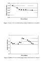
NL/hr/gram of catalyst and an inlet H2/CO ratio of 2.0. Figure 3
shows a plot of the relative carbon monoxide conversion (initial
carbon monoxide conversion = 1) with time on stream. This is a
typical plot illustrating catalyst deactivation with time for a
Fischer-Tropsch catalyst. There is an initial period of rapid
deactivation followed by a subsequent relatively slow period of
deactivation. As shown in Figure 3, the relative carbon monoxide
conversion is 0.62 at the end of the run.
Example 2
A Fischer-Tropsch reaction was carried out over a cobalt
based catalyst in a 1 liter continuous-flow slurry stirred tank
reactor at 220 °C, 350 psig, a syngas space velocity of 7.9
NL/hr/gram of catalyst and an inlet H2/CO ratio of 2.0. Further,
inert argon gas was co-fed with syngas to the reactor such that
16.5 mole percent of the total reactor feed was argon. After the
catalyst had reached a steady state CO conversion for 140 hours,
water was co-fed to the reactor along with the syngas/argon.
After 48 hours of water co-feed, the amount of water flow was
increased. There were four such increases in the flow rate of
water. Each increase was followed by 48 hours of constant water
flow. During water co-feed, the flow rate of argon was decreased
proportionately such that the total mole fraction of water and
argon was maintained at 16.5 mole percent of reactor feed
(balance syngas).
The CO conversion decreased during the co-feeding of water.
Table 1 shows the relative CO conversion of the catalyst 48 hours
after the addition of water at the four different flow rates of
water used. The water flow rate is quantified by the mole
fraction of water at the entrance of the reactor. The data shows
that water is a major cause of deactivation of the Fischer-Tropsch
catalyst. It has been shown in the literature (see, for
example, HILMEN, SCHANKE ET AL., Applied Catalysis, 186 (1999) 169-188)
that water oxidizes the cobalt active metal to inactive
cobalt oxide.
| Effect of co-feeding water on Relative carbon monoxide |
| Mole % of Water in Reactor Feed | Relative CO Conversion |
| 0.0 | 1.00 |
| 1.6 | 0.99 |
| 4.9 | 0.87 |
| 8.8 | 0.75 |
| 11.2 | 0.66 |
conversions
A Fischer-Tropsch reaction was carried out over a cobalt
based catalyst in a 1 liter continuous-flow slurry stirred tank
reactor at 225 °C, 350 psig, a syngas space velocity of 9.0
NL/hr/gram of catalyst and an inlet H2/CO ratio of 2.0. After
steady state CO conversion was reached at these conditions, the
space velocity was decreased to 5.5 NL/hr/gram of catalyst. The
CO conversion immediately increased to a higher value but
subsequently decreased due to catalyst deactivation to a lower
value. The relative CO conversion of the catalyst is taken as
1.0 at the highest CO conversion. Figure 4 shows the relative CO
conversion of the catalyst with time on stream. The catalyst
after deactivation reached a relative CO conversion of 0.65.
This is one more example of catalyst deactivation caused by
high values of carbon monoxide conversion. Note that the
concentration of water, a product of the Fischer-Tropsch
reaction, is higher at higher CO conversion.
Example 4
A regeneration procedure was carried out on catalyst
material deactivated as described in Example 1. The regeneration
was carried out inside the Fischer-Tropsch reactor in two steps-stripping
and reactivation. In the first step (stripping), the
flow of syngas to the reactor was stopped and the flow of
hydrogen was started at a flow rate of 4 NL/hour/gram of
catalyst. The reactor pressure was decreased to 100 psig. The
reactor was maintained at the same temperature as during the
Fischer-Tropsch reaction (225 °C) for 2 hours. In the second step
(reactivation), the reactor temperature was increased to 300 °C at
the rate of 1 °C per minute. The reactor was maintained at this
temperature of 300 °C for 16 hours.
After the regeneration, the reactor was cooled to the
earlier Fischer-Tropsch reaction temperature of 225 °C, the
reactor was pressurized to the earlier Fischer-Tropsch pressure
of 350 psig, hydrogen flow was stopped and syngas flow re-started
at the earlier space velocity of 6 NL/hr/gram of catalyst. The
CO conversion was measured after 4 and 24 hours after the
Fischer-Tropsch reaction was re-started.
Example 5
A regeneration procedure was carried out on catalyst
material deactivated as described in Example 1. The regeneration
was carried out inside the Fischer-Tropsch reactor in two steps-stripping
and reactivation. In the first step (stripping), the
flow of syngas to the reactor was stopped and the flow of
hydrogen was started at a flow rate of 4 NL/hour/gram of
catalyst. The reactor pressure was decreased to 100 psig. The
reactor was maintained at the same temperature as during the
Fischer-Tropsch reaction (225 °C) for 24 hours. In the second
step (reactivation), the reactor temperature was increased to 300
°C at the rate of 1 °C per minute. The reactor was maintained at
this temperature of 300 °C for 16 hours.
After the regeneration, the reactor was cooled to the
earlier Fischer-Tropsch reaction temperature of 225 °C, the
reactor was pressurized to the earlier Fischer-Tropsch pressure
of 350 psig, hydrogen flow was stopped and syngas flow re-started
at the earlier space velocity of 6 NL/hr/gram of catalyst. The
CO conversion was measured after 4 and 24 hours after the
Fischer-Tropsch reaction was re-started.
Example 6
A regeneration procedure was carried out on catalyst
material deactivated as described in Example 3. The regeneration
was carried out inside the Fischer-Tropsch reactor in two steps-stripping
and reactivation. In the first step (stripping), the
flow of syngas to the reactor was stopped and the flow of
hydrogen was started at a flow rate of 4 NL/hour/gram of
catalyst. The reactor pressure was decreased to 100 psig. The
reactor was maintained at the same temperature as during the
Fischer-Tropsch reaction (225 °C) for 24 hours. In the second
step (reactivation), the reactor temperature was increased to 300
°C at the rate of 1 °C per minute. The reactor was maintained at
this temperature of 300 °C for 16 hours.
After the regeneration, the reactor was cooled to the
earlier Fischer-Tropsch reaction temperature of 225 °C, the
reactor was pressurized to the earlier Fischer-Tropsch pressure
of 350 psig, hydrogen flow was stopped and syngas flow re-started
at the earlier space velocity of 6 NL/hr/gram of catalyst. The
CO conversion was measured after 4 and 24 hours after the
Fischer-Tropsch reaction was re-started.
Example 7
A Fischer-Tropsch reaction was carried out using a cobalt
based catalyst under conditions that slowly deactivate the
catalyst from an initial relative CO conversion of 1.0 to a
relative CO conversion of 0.77. The regeneration was carried out
inside the Fischer-Tropsch reactor. Only the stripping step was
used. In the stripping step, the flow of syngas to the reactor
was stopped and the flow of hydrogen was started at a flow rate
of 4 NL/hour/gram of catalyst. The reactor pressure was
decreased to 70 psig. The reactor was maintained at the same
temperature as during the Fischer-Tropsch reaction (230 °C) for 16
hours.
After the regeneration, the reactor was pressurized to the
earlier Fischer-Tropsch pressure of 350 psig, the hydrogen flow
was stopped and syngas flow re-started at the earlier space
velocity of 6 NL/hr/gram of catalyst. The CO conversion was
measured after 4 and 24 hours after the Fischer-Tropsch reaction
was re-started.
Example 8
After catalyst deactivation and an attempted regeneration in
Example 7, another attempt was made to regenerate the catalyst.
The regeneration was carried out inside the Fischer-Tropsch
reactor. Only the stripping step was used. In the stripping
step, the flow of syngas to the reactor was stopped and the flow
of hydrogen was started at a flow rate of 4 NL/hour/gram of
catalyst. The reactor pressure was decreased to 70 psig. The
reactor was maintained at the same temperature as during the
Fischer-Tropsch reaction (230 °C) for 48 hours.
After the regeneration, the reactor was pressurized to the
earlier Fischer-Tropsch pressure of 350 psig, the hydrogen flow
was stopped and syngas flow re-started at the earlier space
velocity of 6 NL/hr/gram of catalyst. The CO conversion was
measured after 4 and 24 hours after the Fischer-Tropsch reaction
was re-started.
Example 9
After catalyst deactivation and the successful regeneration
and re-deactivation in Example 8, another attempt was made to
regenerate the catalyst. The regeneration was carried out inside
the Fischer-Tropsch reactor. Only the stripping step was
followed. In the stripping step, the flow of syngas to the
reactor was maintained the same as during reaction at 6
NL/hr/gram of catalyst. The reactor pressure was decreased to 70
psig. The reactor was maintained at the same temperature as
during the Fischer-Tropsch reaction (230 °C) for 48 hours.
After the regeneration, the reactor pressure was increased
to its original value of 350 psig. The CO conversion was measured
after 4 and 24 hours after the Fischer-Tropsch reaction was re-started.
The regeneration conditions and results of the Examples are
summarized in Table 2 below.
| Regeneration Conditions and Results of Examples 4 to 13 |
| Example | Regeneration Conditions | Relative CO Conversion |
| # | Stripping | Reactivation | Initial | Before | After |
| | Temp. | Press. | Time | Gas Used | Temp. | Press. | Time | Gas Used | | Regen | Regen |
| | deg. C | psig | hrs | | deg. C | psig | hrs |
| 4 | 225 | 100 | 2 | H2 | 300 | 100 | 16 | H2 | 1 | 0.62 | 0.62 |
| 5 | 225 | 100 | 24 | H2 | 300 | 100 | 16 | H2 | 1 | 0.62 | 1.02 |
| 6 | 225 | 100 | 24 | H2 | 300 | 100 | 16 | H2 | 1 | 0.65 | 1.05 |
| 7 | 230 | 70 | 16 | H2 | - | - | - | - | 1 | 0.77 | 0.77 |
| 8 | 230 | 70 | 48 | H2 | - | - | - | - | 1 | 0.77 | 1 |
| 9 | 230 | 70 | 48 | H2/CO 2:1 | - | - | - | - | 1 | 0.77 | 1 |
The data in Table 2 shows that the regeneration process in
accordance with the present invention restores a deactivated
catalyst to its original CO conversion values or better.
Examples 4 and 7 showed no indication of regeneration for the
deactivated catalyst material. It is believed that the data
suggests that the stripping procedure, when used as a precursor
for the regeneration step, should be carried out for greater than
2 hours if conducted at 225°C and 100 psia. Likewise, a stand
alone stripping process at 230°C and 70 psia should be carried out
for greater than 16 hours. Of course, changing the other
stripping operating conditions may alter the results. For
example, the Examples represented in Table 2 were carried out at
the preferred optimum temperature ranges. Using similar
operating parameters, higher temperatures, e.g., greater than
350°C, may actually lower the CO conversion value of the catalyst
material.
Also, the data from Example 9 shows that the gas used for
stripping does not necessarily have to be high-purity hydrogen.
In fact, the stripping gas may contain up to about 33 mole % of
carbon monoxide, but it is preferred that the carbon monoxide be
less than about 30 mole %, more preferably less than about 20
mole %, and still more preferably less than about 10 mole %.
Further, since it is very likely that there was some amount of
reaction occurring during stripping, this shows that under at
least the conditions presented the reaction is not detrimental to
the stripping/regeneration procedure.
While preferred embodiments of this invention have been
shown and described, modification thereof can be made by one
skilled in the art without departing from the spirit or teaching
of this invention. The embodiments described herein are
exemplary only and are not limiting. Many variations and
modifications of the processes are possible and are within the
scope of this invention. For example, it is possible that the
stripping gas and regeneration gas are the same. The stripping
gas does not have to include hydrogen but the regeneration gas
will preferably include hydrogen. Accordingly, the scope of
protection is not limited to the embodiments described herein,
but is only limited by the claims that follow, the scope of which
shall include all equivalents of the subject matter of the
claims. For example, although the term regeneration is
frequently used the term "treatment" would also be an adequate
description and should be interchangeably understood. In
addition, unless order is explicitly recited, the recitation of
steps in a claim is not intended to require that the steps be
performed in any particular order, or that any step must be
completed before the beginning of another step.