EP1400381A1 - Mischvorrichtung zum Mischen von kalter und warmer Luft, insbesondere für eine Heizungs- oder Klimaanlage eines Kraftfahrzeugs - Google Patents
Mischvorrichtung zum Mischen von kalter und warmer Luft, insbesondere für eine Heizungs- oder Klimaanlage eines Kraftfahrzeugs Download PDFInfo
- Publication number
- EP1400381A1 EP1400381A1 EP03019411A EP03019411A EP1400381A1 EP 1400381 A1 EP1400381 A1 EP 1400381A1 EP 03019411 A EP03019411 A EP 03019411A EP 03019411 A EP03019411 A EP 03019411A EP 1400381 A1 EP1400381 A1 EP 1400381A1
- Authority
- EP
- European Patent Office
- Prior art keywords
- mixing device
- channels
- air inlet
- cold
- mixing
- Prior art date
- Legal status (The legal status is an assumption and is not a legal conclusion. Google has not performed a legal analysis and makes no representation as to the accuracy of the status listed.)
- Granted
Links
Images

Classifications
-
- B—PERFORMING OPERATIONS; TRANSPORTING
- B60—VEHICLES IN GENERAL
- B60H—ARRANGEMENTS OF HEATING, COOLING, VENTILATING OR OTHER AIR-TREATING DEVICES SPECIALLY ADAPTED FOR PASSENGER OR GOODS SPACES OF VEHICLES
- B60H1/00—Heating, cooling or ventilating devices
- B60H1/00507—Details, e.g. mounting arrangements, desaeration devices
- B60H1/00557—Details of ducts or cables
- B60H1/00564—Details of ducts or cables of air ducts
-
- F—MECHANICAL ENGINEERING; LIGHTING; HEATING; WEAPONS; BLASTING
- F24—HEATING; RANGES; VENTILATING
- F24F—AIR-CONDITIONING; AIR-HUMIDIFICATION; VENTILATION; USE OF AIR CURRENTS FOR SCREENING
- F24F13/00—Details common to, or for air-conditioning, air-humidification, ventilation or use of air currents for screening
- F24F13/02—Ducting arrangements
- F24F13/04—Air-mixing units
-
- B—PERFORMING OPERATIONS; TRANSPORTING
- B60—VEHICLES IN GENERAL
- B60H—ARRANGEMENTS OF HEATING, COOLING, VENTILATING OR OTHER AIR-TREATING DEVICES SPECIALLY ADAPTED FOR PASSENGER OR GOODS SPACES OF VEHICLES
- B60H1/00—Heating, cooling or ventilating devices
- B60H1/00007—Combined heating, ventilating, or cooling devices
- B60H1/00021—Air flow details of HVAC devices
- B60H2001/00078—Assembling, manufacturing or layout details
- B60H2001/00092—Assembling, manufacturing or layout details of air deflecting or air directing means inside the device
Definitions
- the invention relates to a mixing device for mixing cold and warm air, especially for a heating or air conditioning system Motor vehicle, according to the preamble of claim 1.
- Air mixing device for a heating or air conditioning system of a motor vehicle known, with a cold air inlet and a warm air inlet as well an outlet for a mixed air flow, with several of parallel channel walls formed channels that connect to the air inlets, and with built-up of several slats shutter valves for opening and Closing the air inlets.
- a mixing device for mixing cold and warm air, each with a cold air inlet and a hot air inlet are provided, which has a region in which the cold air inlet and the hot air inlet parallel to each other. there Both inlets have a semi-circular cross section and are separated by a partition.
- Such a mixing device can simple manner be designed as a plastic injection molded part and therefore offers significant cost advantages compared to conventional mixing devices.
- the mixing device is perpendicular to one in radial Direction according to the dividing wall extending axis and slightly in Flow direction inclined channels.
- the channels are gap in the cold air inlet and hot air inlet arranged. This allows for optimal replacement of the cold and warm air and also provides increased stability of the mixing device. Also with regard to the production as a plastic injection molded part offers Such an embodiment advantages.
- the backs of the channels are circular, oval or in particular rounded off in a flowing line. This reduces the flow resistance the mixing device.
- each inlet are five to ten, in particular arranged six to seven channels, with the number of channels on the two sides can differ by one or two.
- the channel-free width preferably starts from the dividing wall towards the edge of the outlet towards, whereby the flow in the channel is optimized. Accordingly, the channel width that leads to the other inlet increases towards the edge.
- the channels are arcuate. This optimizes the Flow in the channels and ensures a good mixing.
- there the channels are in particular designed such that the angle to normal flow direction towards the edge of the mixed air outlet towards increases.
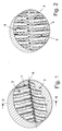
- a mixing device 1 according to the invention in the form of a plastic injection molded part with a cold air inlet 2, a hot air inlet 3 and a mixed air outlet 4 is formed such that the two inlets. 2 and 3 each have a semicircular cross section through a partition wall 5 are separated and complement each other to a circle whose cross-section corresponds to the outlet 4.
- the two inlets 3 and 4 run in an area parallel to each other. This area can for example by another part (not shown) or integral with the one described Mixing device 1 are formed, which is a transition area in that the inlets 2 and 3 from an initially circular Cross-section converted into the said semicircular cross-section and merged.
- the channels 6 are formed in such a way that they are approximately streamlined Back 7 a slight arc of the partition 5 starting makes the wall area, the angle to the normal flow direction increases in the direction of the wall area, but at the end even smaller than 90 ° is. Further, the width of the channels increases from the partition wall 5 towards the wall area out, so that the freely flow-through area 8 wider becomes.
- the walls 9 of the channels end over the entire channel length at the same height of the mixed air outlet 4 (see Fig. 3).
- seven channels 6 are provided, the cold air in the area behind the warm air inlet 3 and six Channels 6 are provided, the hot air in the area behind the cold air inlet 2 lead.
Landscapes
- Engineering & Computer Science (AREA)
- Mechanical Engineering (AREA)
- Chemical & Material Sciences (AREA)
- Combustion & Propulsion (AREA)
- General Engineering & Computer Science (AREA)
- Physics & Mathematics (AREA)
- Thermal Sciences (AREA)
- Air-Conditioning For Vehicles (AREA)
Abstract
Description
- Fig. 1
- eine Ansicht der Mischvorrichtung mit Blick auf die von der Luft angeströmte Seite,
- Fig. 2
- eine Ansicht mit Blick auf die entgegengesetzte Seite von Fig. 1, und
- Fig. 3
- einen Schnitt in Längsrichtung mit einer schematischen Darstellung des Strömungsverlaufs.
Claims (11)
- Mischvorrichtung zum Mischen von kalter und warmer Luft, insbesondere für eine Heizungs- oder Klimaanlage eines Kraftfahrzeugs, mit einem Kaltluft-Einlass (2) und einem Warmluft-Einlass (3) sowie einem Mischluft-Auslass (4), dadurch gekennzeichnet, dass die Mischvorrichtung (1) einen Bereich aufweist, in dem der Kaltluft-Einlass (2) und der Warmluft-Einlass (3) parallel zueinander verlaufen, beide Einlässe (2, 3) einen halbkreisförmigen Querschnitt aufweisen und die beiden Einlässe (2, 3) durch eine Trennwand (5) getrennt sind.
- Mischvorrichtung nach Anspruch 1, dadurch gekennzeichnet, dass die Mischvorrichtung (1) senkrecht zu einer in radialer Richtung entsprechend der Trennwand (5) verlaufenden Achse (A) und leicht in Strömungsrichtung geneigte Kanäle (6) aufweist.
- Mischvorrichtung nach Anspruch 2, dadurch gekennzeichnet, dass die Kanäle (6) auf Lücke im Kaltluft-Einlass (2) und Warmluft-Einlass (3) angeordnet sind.
- Mischvorrichtung nach einem Ansprüche 2 bis 3, dadurch gekennzeichnet, dass die Rücken (7) der Kanäle (6) kreisförmig, oval oder strömungslinienförmig abgerundet sind.
- Mischvorrichtung nach einem Ansprüche 2 bis 4, dadurch gekennzeichnet, dass in jedem Einlass (2, 3) fünf bis zehn, insbesondere sechs bis acht Kanäle angeordnet sind.
- Mischvorrichtung nach einem Ansprüche 2 bis 5, dadurch gekennzeichnet, dass die kanalfreie Breite von der Trennwand (5) ausgehend zum Rand des Auslasses (4) hin zunimmt.
- Mischvorrichtung nach einem Ansprüche 2 bis 6, dadurch gekennzeichnet, dass die von einem Einlass (2 oder 3) zum anderen Einlass (3 bzw. 2) führende Kanalbreite zum Rand hin abnimmt.
- Mischvorrichtung nach einem Ansprüche 2 bis 7, dadurch gekennzeichnet, dass die Kanäle (6) bogenförmig ausgebildet sind.
- Mischvorrichtung nach Anspruch 8, dadurch gekennzeichnet, dass die Kanäle (6) derart ausgebildet sind, dass der Winkel zur normalen Strömungsrichtung zum Rand des Mischluft-Auslasses (4) hin zunimmt.
- Mischvorrichtung nach einem der vorhergehenden Ansprüche, dadurch gekennzeichnet, dass die Mischvorrichtung (1) ein Kunststoff-Spritzgussteil ist.
- Mischvorrichtung nach einem der vorhergehenden Ansprüche, dadurch gekennzeichnet, dass die Einlässe (2, 3) derart ausgebildet sind, dass sich der Querschnitt über die Länge hinweg von einem kreisförmigen Querschnitt zu einem halbkreisförmigen Querschnitt ändert.
Applications Claiming Priority (2)
| Application Number | Priority Date | Filing Date | Title |
|---|---|---|---|
| DE10243658 | 2002-09-19 | ||
| DE2002143658 DE10243658A1 (de) | 2002-09-19 | 2002-09-19 | Mischvorrichtung zum Mischen von kalter und warmer Luft, insbesondere für eine Heizungs-oder Klimaanlage eines Kraftfahrzeugs |
Publications (2)
| Publication Number | Publication Date |
|---|---|
| EP1400381A1 true EP1400381A1 (de) | 2004-03-24 |
| EP1400381B1 EP1400381B1 (de) | 2009-10-28 |
Family
ID=31896212
Family Applications (1)
| Application Number | Title | Priority Date | Filing Date |
|---|---|---|---|
| EP20030019411 Expired - Lifetime EP1400381B1 (de) | 2002-09-19 | 2003-08-28 | Mischvorrichtung zum Mischen von kalter und warmer Luft, insbesondere für eine Heizungs- oder Klimaanlage eines Kraftfahrzeugs |
Country Status (2)
| Country | Link |
|---|---|
| EP (1) | EP1400381B1 (de) |
| DE (2) | DE10243658A1 (de) |
Cited By (3)
| Publication number | Priority date | Publication date | Assignee | Title |
|---|---|---|---|---|
| EP2080650A1 (de) * | 2008-01-21 | 2009-07-22 | Behr France Rouffach SAS | Vorrichtung zur Heizung eines Luftstroms |
| WO2013000958A1 (de) * | 2011-06-28 | 2013-01-03 | Behr Gmbh & Co. Kg | Mischer zur mischung von luftströmen |
| US20150021006A1 (en) * | 2013-07-16 | 2015-01-22 | The Boeing Company | Methods and device for mixing airflows in environmental control systems |
Families Citing this family (1)
| Publication number | Priority date | Publication date | Assignee | Title |
|---|---|---|---|---|
| DE102005051518A1 (de) | 2005-10-26 | 2007-05-03 | Behr Gmbh & Co. Kg | Kraftfahrzeug-Klimaanlage |
Citations (5)
| Publication number | Priority date | Publication date | Assignee | Title |
|---|---|---|---|---|
| GB612012A (en) * | 1945-10-09 | 1948-11-08 | Harry Stewart Wheller | Improvements in mixing chamber for use in heating or cooling devices |
| GB705572A (en) * | 1949-05-07 | 1954-03-17 | Daimler Benz Ag | Improvements relating to the heating and ventilation of motor vehicles |
| US2860567A (en) * | 1953-07-02 | 1958-11-18 | Daimler Benz Ag | Heating and ventilating system for motor vehicles |
| DE2455339A1 (de) * | 1974-11-22 | 1976-08-12 | Opel Adam Ag | Vorrichtung zum heizen und belueften von kraftfahrzeugen |
| DE3908660A1 (de) * | 1988-03-22 | 1989-10-12 | Valeo | Heiz- und/oder klimaanlage fuer ein kraftfahrzeug |
Family Cites Families (2)
| Publication number | Priority date | Publication date | Assignee | Title |
|---|---|---|---|---|
| DE19826990B4 (de) * | 1998-06-18 | 2007-01-25 | Behr Gmbh & Co. Kg | Luftmischeinrichtung für eine Heizungs- oder Klimaanlage eines Kraftfahrzeuges |
| JP4173646B2 (ja) | 2001-03-16 | 2008-10-29 | カルソニックカンセイ株式会社 | 車両用空調装置 |
-
2002
- 2002-09-19 DE DE2002143658 patent/DE10243658A1/de not_active Withdrawn
-
2003
- 2003-08-28 DE DE50312067T patent/DE50312067D1/de not_active Expired - Lifetime
- 2003-08-28 EP EP20030019411 patent/EP1400381B1/de not_active Expired - Lifetime
Patent Citations (5)
| Publication number | Priority date | Publication date | Assignee | Title |
|---|---|---|---|---|
| GB612012A (en) * | 1945-10-09 | 1948-11-08 | Harry Stewart Wheller | Improvements in mixing chamber for use in heating or cooling devices |
| GB705572A (en) * | 1949-05-07 | 1954-03-17 | Daimler Benz Ag | Improvements relating to the heating and ventilation of motor vehicles |
| US2860567A (en) * | 1953-07-02 | 1958-11-18 | Daimler Benz Ag | Heating and ventilating system for motor vehicles |
| DE2455339A1 (de) * | 1974-11-22 | 1976-08-12 | Opel Adam Ag | Vorrichtung zum heizen und belueften von kraftfahrzeugen |
| DE3908660A1 (de) * | 1988-03-22 | 1989-10-12 | Valeo | Heiz- und/oder klimaanlage fuer ein kraftfahrzeug |
Cited By (5)
| Publication number | Priority date | Publication date | Assignee | Title |
|---|---|---|---|---|
| EP2080650A1 (de) * | 2008-01-21 | 2009-07-22 | Behr France Rouffach SAS | Vorrichtung zur Heizung eines Luftstroms |
| WO2013000958A1 (de) * | 2011-06-28 | 2013-01-03 | Behr Gmbh & Co. Kg | Mischer zur mischung von luftströmen |
| US9423147B2 (en) | 2011-06-28 | 2016-08-23 | Mahle International Gmbh | Mixer for mixing air flows |
| US20150021006A1 (en) * | 2013-07-16 | 2015-01-22 | The Boeing Company | Methods and device for mixing airflows in environmental control systems |
| US9783309B2 (en) * | 2013-07-16 | 2017-10-10 | The Boeing Company | Methods and device for mixing airflows in environmental control systems |
Also Published As
| Publication number | Publication date |
|---|---|
| DE10243658A1 (de) | 2004-04-01 |
| DE50312067D1 (de) | 2009-12-10 |
| EP1400381B1 (de) | 2009-10-28 |
Similar Documents
| Publication | Publication Date | Title |
|---|---|---|
| DE69920818T2 (de) | Sequentieller mischplattenschieber | |
| DE102006043647B4 (de) | Steuerventilanordnung mit verbesserter Strömungscharakteristik | |
| EP2800892B1 (de) | Mischventil | |
| DE60026753T2 (de) | Mischungsklappeantriebsvorrichtung einer Kraftfahrzeug-Klimaanlage | |
| DE29704286U1 (de) | Sanitäre Auslaufvorrichtung | |
| DE102009057814A1 (de) | Klimaanlage für Fahrzeuge | |
| DE102006002663B4 (de) | Ausströmdüse mit Lamellen und Kraftfahrzeug mit Innenraum | |
| DE102011011710A1 (de) | Luftmischungs- und -verteilungsvorrichtung und Fahrzeugheizungs- oder -klimaanlage | |
| EP2072297B1 (de) | Klappe, insbesondere für einen Luftkanal | |
| EP1713653B1 (de) | Ein luftmischer für ein lüftungssystem | |
| DE3422182A1 (de) | Gehaeuse fuer eine heiz- oder klimatisierungsvorrichtung fuer ein kraftfahrzeug | |
| DE60029836T2 (de) | Heizungs- und Klimaanlage mit einer Luftmischklappe | |
| EP1312493B1 (de) | Luftmischeinrichtung für eine Heizungs- oder Klimaanlage | |
| DE19834575C5 (de) | Drehschieberventil | |
| EP1400381B1 (de) | Mischvorrichtung zum Mischen von kalter und warmer Luft, insbesondere für eine Heizungs- oder Klimaanlage eines Kraftfahrzeugs | |
| DE102004029490A1 (de) | Klappe für ein Luftführungsgehäuse einer Kraftfahrzeug-Klimaanlage | |
| DE102019131554B4 (de) | Luftauslassvorrichtung für den Auslass einer Luftströmung | |
| WO2012069516A1 (de) | Fahrzeugbelüftungssystem | |
| EP2050598B1 (de) | Klappenanordnung, für eine Fahrzeug-Klimaanlage | |
| DE10208852C1 (de) | Abschlusskappenanordnung für eine Wärmetauscheranordnung, insbesondere für ein Fahrzeugheizgerät | |
| EP2407324B1 (de) | Luftregulierungselement für eine Heizungs- und Belüftungsvorrichtung für ein Kraftfahrzeug sowie Heizungs- und Belüftungsvorrichtung für einen Fahrgastraum eines Kraftfahrzeuges | |
| EP1738941A1 (de) | Kraftfahrzeug-Klimaanlage | |
| EP1759897A1 (de) | Luftstromschalteinrichtung | |
| DE4109101A1 (de) | Einbau fuer mischkammern stroemungstechnischer anlagen | |
| DE102007020724A1 (de) | Klimagerät für Kraftfahrzeuge |
Legal Events
| Date | Code | Title | Description |
|---|---|---|---|
| PUAI | Public reference made under article 153(3) epc to a published international application that has entered the european phase |
Free format text: ORIGINAL CODE: 0009012 |
|
| AK | Designated contracting states |
Kind code of ref document: A1 Designated state(s): AT BE BG CH CY CZ DE DK EE ES FI FR GB GR HU IE IT LI LU MC NL PT RO SE SI SK TR |
|
| AX | Request for extension of the european patent |
Extension state: AL LT LV MK |
|
| 17P | Request for examination filed |
Effective date: 20040924 |
|
| AKX | Designation fees paid |
Designated state(s): DE FR |
|
| RAP1 | Party data changed (applicant data changed or rights of an application transferred) |
Owner name: BEHR GMBH & CO. KG |
|
| 17Q | First examination report despatched |
Effective date: 20060926 |
|
| GRAP | Despatch of communication of intention to grant a patent |
Free format text: ORIGINAL CODE: EPIDOSNIGR1 |
|
| GRAS | Grant fee paid |
Free format text: ORIGINAL CODE: EPIDOSNIGR3 |
|
| GRAA | (expected) grant |
Free format text: ORIGINAL CODE: 0009210 |
|
| AK | Designated contracting states |
Kind code of ref document: B1 Designated state(s): DE FR |
|
| REF | Corresponds to: |
Ref document number: 50312067 Country of ref document: DE Date of ref document: 20091210 Kind code of ref document: P |
|
| PLBE | No opposition filed within time limit |
Free format text: ORIGINAL CODE: 0009261 |
|
| STAA | Information on the status of an ep patent application or granted ep patent |
Free format text: STATUS: NO OPPOSITION FILED WITHIN TIME LIMIT |
|
| 26N | No opposition filed |
Effective date: 20100729 |
|
| PGFP | Annual fee paid to national office [announced via postgrant information from national office to epo] |
Ref country code: FR Payment date: 20100901 Year of fee payment: 8 |
|
| REG | Reference to a national code |
Ref country code: FR Ref legal event code: ST Effective date: 20120430 |
|
| PG25 | Lapsed in a contracting state [announced via postgrant information from national office to epo] |
Ref country code: FR Free format text: LAPSE BECAUSE OF NON-PAYMENT OF DUE FEES Effective date: 20110831 |
|
| REG | Reference to a national code |
Ref country code: DE Ref legal event code: R082 Ref document number: 50312067 Country of ref document: DE Representative=s name: GRAUEL, ANDREAS, DIPL.-PHYS. DR. RER. NAT., DE |
|
| REG | Reference to a national code |
Ref country code: DE Ref legal event code: R082 Ref document number: 50312067 Country of ref document: DE Representative=s name: GRAUEL, ANDREAS, DIPL.-PHYS. DR. RER. NAT., DE Effective date: 20150224 Ref country code: DE Ref legal event code: R081 Ref document number: 50312067 Country of ref document: DE Owner name: MAHLE INTERNATIONAL GMBH, DE Free format text: FORMER OWNER: BEHR GMBH & CO. KG, 70469 STUTTGART, DE Effective date: 20150224 |
|
| PGFP | Annual fee paid to national office [announced via postgrant information from national office to epo] |
Ref country code: DE Payment date: 20180831 Year of fee payment: 16 |
|
| REG | Reference to a national code |
Ref country code: DE Ref legal event code: R119 Ref document number: 50312067 Country of ref document: DE |
|
| PG25 | Lapsed in a contracting state [announced via postgrant information from national office to epo] |
Ref country code: DE Free format text: LAPSE BECAUSE OF NON-PAYMENT OF DUE FEES Effective date: 20200303 |