EP1400332A1 - Method and apparatus for dosing an additive in the inlet of an injection moulding press, and injection moulding press fitted with a dosing apparatus - Google Patents
Method and apparatus for dosing an additive in the inlet of an injection moulding press, and injection moulding press fitted with a dosing apparatus Download PDFInfo
- Publication number
- EP1400332A1 EP1400332A1 EP02020872A EP02020872A EP1400332A1 EP 1400332 A1 EP1400332 A1 EP 1400332A1 EP 02020872 A EP02020872 A EP 02020872A EP 02020872 A EP02020872 A EP 02020872A EP 1400332 A1 EP1400332 A1 EP 1400332A1
- Authority
- EP
- European Patent Office
- Prior art keywords
- additive
- phase
- extrusion screw
- polymer
- injection
- Prior art date
- Legal status (The legal status is an assumption and is not a legal conclusion. Google has not performed a legal analysis and makes no representation as to the accuracy of the status listed.)
- Granted
Links
Images

Classifications
-
- B—PERFORMING OPERATIONS; TRANSPORTING
- B29—WORKING OF PLASTICS; WORKING OF SUBSTANCES IN A PLASTIC STATE IN GENERAL
- B29C—SHAPING OR JOINING OF PLASTICS; SHAPING OF MATERIAL IN A PLASTIC STATE, NOT OTHERWISE PROVIDED FOR; AFTER-TREATMENT OF THE SHAPED PRODUCTS, e.g. REPAIRING
- B29C45/00—Injection moulding, i.e. forcing the required volume of moulding material through a nozzle into a closed mould; Apparatus therefor
- B29C45/17—Component parts, details or accessories; Auxiliary operations
- B29C45/46—Means for plasticising or homogenising the moulding material or forcing it into the mould
- B29C45/53—Means for plasticising or homogenising the moulding material or forcing it into the mould using injection ram or piston
- B29C45/54—Means for plasticising or homogenising the moulding material or forcing it into the mould using injection ram or piston and plasticising screw
-
- B—PERFORMING OPERATIONS; TRANSPORTING
- B29—WORKING OF PLASTICS; WORKING OF SUBSTANCES IN A PLASTIC STATE IN GENERAL
- B29C—SHAPING OR JOINING OF PLASTICS; SHAPING OF MATERIAL IN A PLASTIC STATE, NOT OTHERWISE PROVIDED FOR; AFTER-TREATMENT OF THE SHAPED PRODUCTS, e.g. REPAIRING
- B29C45/00—Injection moulding, i.e. forcing the required volume of moulding material through a nozzle into a closed mould; Apparatus therefor
- B29C45/17—Component parts, details or accessories; Auxiliary operations
- B29C45/18—Feeding the material into the injection moulding apparatus, i.e. feeding the non-plastified material into the injection unit
- B29C45/1816—Feeding auxiliary material, e.g. colouring material
-
- B—PERFORMING OPERATIONS; TRANSPORTING
- B29—WORKING OF PLASTICS; WORKING OF SUBSTANCES IN A PLASTIC STATE IN GENERAL
- B29C—SHAPING OR JOINING OF PLASTICS; SHAPING OF MATERIAL IN A PLASTIC STATE, NOT OTHERWISE PROVIDED FOR; AFTER-TREATMENT OF THE SHAPED PRODUCTS, e.g. REPAIRING
- B29C45/00—Injection moulding, i.e. forcing the required volume of moulding material through a nozzle into a closed mould; Apparatus therefor
- B29C45/17—Component parts, details or accessories; Auxiliary operations
- B29C45/76—Measuring, controlling or regulating
-
- B—PERFORMING OPERATIONS; TRANSPORTING
- B29—WORKING OF PLASTICS; WORKING OF SUBSTANCES IN A PLASTIC STATE IN GENERAL
- B29C—SHAPING OR JOINING OF PLASTICS; SHAPING OF MATERIAL IN A PLASTIC STATE, NOT OTHERWISE PROVIDED FOR; AFTER-TREATMENT OF THE SHAPED PRODUCTS, e.g. REPAIRING
- B29C45/00—Injection moulding, i.e. forcing the required volume of moulding material through a nozzle into a closed mould; Apparatus therefor
- B29C45/17—Component parts, details or accessories; Auxiliary operations
- B29C45/46—Means for plasticising or homogenising the moulding material or forcing it into the mould
- B29C45/461—Injection of measured doses
-
- B—PERFORMING OPERATIONS; TRANSPORTING
- B29—WORKING OF PLASTICS; WORKING OF SUBSTANCES IN A PLASTIC STATE IN GENERAL
- B29K—INDEXING SCHEME ASSOCIATED WITH SUBCLASSES B29B, B29C OR B29D, RELATING TO MOULDING MATERIALS OR TO MATERIALS FOR MOULDS, REINFORCEMENTS, FILLERS OR PREFORMED PARTS, e.g. INSERTS
- B29K2067/00—Use of polyesters or derivatives thereof, as moulding material
-
- B—PERFORMING OPERATIONS; TRANSPORTING
- B29—WORKING OF PLASTICS; WORKING OF SUBSTANCES IN A PLASTIC STATE IN GENERAL
- B29K—INDEXING SCHEME ASSOCIATED WITH SUBCLASSES B29B, B29C OR B29D, RELATING TO MOULDING MATERIALS OR TO MATERIALS FOR MOULDS, REINFORCEMENTS, FILLERS OR PREFORMED PARTS, e.g. INSERTS
- B29K2105/00—Condition, form or state of moulded material or of the material to be shaped
- B29K2105/0005—Condition, form or state of moulded material or of the material to be shaped containing compounding ingredients
Definitions
- the present invention relates to an improvement made in the field of automatic dosing of an additive, such as for example a dye, at the entrance of an injection molding machine which is fed by gravity with at least one polymer material in the form of granules.
- an additive such as for example a dye
- the invention advantageously, but not exclusively, finds its application to the manufacture of plastic preforms, in particular based on PET (polyethylene terephthalate) by injection into a mold of a mixture polymer / additive.
- the screw extruder usually comprises at minus a worm screw called extrusion screw, rotatably mounted on itself inside a heating sleeve, and equipped on the one hand with an organ motor for its rotational drive on itself, and on the other hand a thrust member, of the piston type, for its forced displacement in forward translation of the sheath, i.e. towards the exit scabbard.
- the barrel of the extrusion screw is continuously supplied, generally by gravity, with at least one polymer material under form of granules.
- the gravity introduction of the polymer granules is made in the rear part of the sheath.
- the polymer granules are dried before introduction into the sheath the extruder, for example by being heated in a drying hopper upstream whose outlet is connected to the inlet inlet of the barrel the extruder.
- injection molding machines There are mainly two types of injection molding machines: injection molding machines with injection pot; direct injection presses, also called reciprocal machines.
- the outlet of the sleeve of the extrusion screw is connected to the inlet of the injection pot by a connection conduit fitted with a valve-type member, or equivalent for closing / opening the duct.
- the injection pot is equipped with a piston which allows the material to be injected into the mold molten polymer present in the injection pot.
- the injection molding machine operates on a repetitive operating cycle including a so-called transfer phase followed by a so-called plasticization phase:
- valve or equivalent between the sheath of the extrusion screw and the injection pot is open, the outlet of the sleeve communicating with the inlet of the injection pot.
- This transfer phase is characterized by a displacement of the extrusion screw in forward translation and under pressure by means of the screw thrust member.
- the material present in the sheath the front of the screw head is thus pushed by the screw towards the outlet of the sleeve and is transferred into the connection pipe and into the injection pot.
- the extrusion screw can, simultaneously with its forced displacement in translation by the thrust member, be or not driven in rotation on herself.
- valve or equivalent between the sheath of the extrusion screw and the injection pot is closed, the outlet of the sleeve being isolated from the inlet of the injection pot.
- This plasticization phase is characterized by training in controlled speed rotation of the extrusion screw along its axis longitudinal.
- the polymer material present in the sheath under the combined effects of temperature and mechanical shear of the material between the screw and the sleeve, gradually passes, as and measurement of its progress in the sheath, from the solid state (granules) to the molten state by being kneaded (progressive plasticization of the material polymer).
- the polymer material which is conveyed towards the front of the sheath pushes back in translation towards rear of the extrusion screw (recoil of the extrusion screw).
- the polymer material is not plasticized necessarily only during the laminating phase but that this plasticization can in certain cases also continue during the aforementioned transfer phase.
- Injection of the polymer material in the molten state present in the pot injection, by means of the auxiliary piston with which said pot is fitted, is performed in masked time during the plasticization phase, which advantageously makes it possible to obtain low operating cycles duration and therefore high production rates and / or design a machine whose plasticization phase can be longer long and less aggressive, and / or design a machine with a shorter screw length for the same plasticizing flow.
- the outlet of the barrel the extruder is designed to be connected directly to the inlet of the injection mold.
- the injection molding machine thus operates on a cycle of repetitive operation including a so-called injection phase followed a plasticization phase.
- the extrusion screw is pushed in translation forward under pressure by means of the screw thrust member.
- the material present in the sheath at the front of the screw head is thus pushed by the screw towards the outlet of the sleeve and is injected directly into the mold at the outlet of the sheath.
- This phase is similar to the plasticization phase previously described for injection molding machines with injection pot.
- the polymer material is not necessarily plasticized only during the plasticization phase, but this plasticization may in some cases also continue during the phase injection.
- the injection of molten polymer material into the mold is produced directly by the extrusion screw, during its translation forward under pressure by the thrust member, not so separated by an auxiliary piston.
- the invention can be applied to any known type of press inject with extrusion screw, and in particular as well with inject with pot and auxiliary injection piston, only with injection presses direct.
- transfer phase will mean not only the previously described transfer phase of a press press cycle inject with injection pot, but also the injection phase of a direct injection press, that is to say more generally the phase during which the extrusion screw is pushed in translation at force forward.
- plasticization phase will mean in a way general the phase during which the extrusion screw is driven only in rotation and moves in translation backwards, and thus covers the aforementioned phase of plasticization of a cycle of a press inject with injection pot or cycle of a direct injection press.
- plastic preforms which are products intermediate and are later intended to be stretched and blown in a mold to form plastic bottles (final products)
- coloring of parts is made by adding a dye to the polymer.
- This dye can be of the solid type (powder or granules) or of the liquid type.
- additives in order to confer properties specific to the final product, it is common to add to the polymer additives, as the case may be in liquid or solid form, which are not necessarily dyes.
- additives additive acetaldehyde reducer, slip agent, additive for blocking UV rays ("UV blocker"), an additive to accelerate the infrared heating, foaming agent, fillers various, for example to reduce the material cost (talc, carbonate of calcium, %), additive to reduce the electrostatic charge of end product, etc ...
- Addition of additive is carried out by introducing the additive into the sheath of the extrusion screw generally through the same intake opening as the polymer.
- the amount of additive added per unit of time is also automatically controlled by means of a dosage.
- This metering device comprises for example a pump peristaltic feed or equivalent in the case of a liquid additive, or a dosing screw or equivalent in the case of an additive in the form of granules or powdery product.
- the metering device (pump, screw, ...) of the metering device is automatically controlled by control means, depending in particular a predetermined setpoint, which is calculated by the operator of the injection molding machine.
- This deposit depends on the total quantity of additive required per cycle depending on the average amount of polymer used in each cycle to mold one or more products and the concentration of additive sought in each molded final product.
- this setpoint is for example the speed of rotation of the dosing screw.
- This setpoint and the estimated duration of a cycle are entered into the dosing as operating parameters of the control means dosing device electronics.
- control means automatically control the metering member to in particular starting from the aforementioned instruction, which instruction is identical and constant for the transfer and plasticization phases of a cycle.
- the means of control can also be designed to account for actual operation of the extrusion screw, by controlling the dosing according to a cycle time which is not a constant predetermined, but which is a variable calculated in each cycle, from the actual measured duration of previous cycles.
- a first drawback is a significant drop (in practice one or more tens of degrees Celsius) of the temperature of the polymer at the inlet of the barrel of the extrusion screw.
- This lowering of temperature is generally detrimental to the process plasticizing the polymer.
- it requires increasing the heating temperature of the barrel of the extrusion screw, which is detrimental to the transformation of the polymer.
- increasing the temperature of screw heating increases the risk of product production secondary from degradation of the polymer, such as acetaldehyde.
- the increase in the heating temperature of the barrel of the extrusion screw constitutes a loss from an energy point of view and thereby increases manufacturing costs.
- a second disadvantage is a damaging generation of dust, due to abrasion of the granules ente them in the mixer.
- a third disadvantage lies in the constraint and the difficulty cleaning the mixer, especially when changing the additive.
- the main objective of the invention is to propose a new solution to the aforementioned problems of lack of uniformity of quantity of additive in the molded product and slip of the extrusion screw of the injection molding machine, that is to say a solution which makes it possible to obtain a more homogeneous additive concentration throughout the final product and which reduces the risk of the screw slipping.
- This solution should also to overcome the aforementioned drawbacks inherent in the solution of the prior art with mixer (additive / polymer premix), and particular should avoid a detrimental lowering of the temperature of the polymer at the entrance of the extrusion screw.
- the aforementioned objective is achieved by means of a new method of dosing of at least one additive at the inlet of an injection molding machine comprising an extrusion screw which is fed continuously and by gravity with at minus a polymer in the form of granules, and which functions according to a repetitive operating cycle comprising a first phase called transfer during which the extrusion screw is moved in translation forward, followed by a second phase called plasticization during which the extrusion screw is driven only in rotation and is moves in translation backwards.
- the additive (A) to be dosed being introduced inside the sheath of the extrusion screw the injection molding machine at the same time as the polymer (P), in order to take into account the difference between the actual polymer input flow (P) in the transfer phase and the actual polymer input flow rate (P) in the phase plasticization, additive (A) is introduced at the inlet of the extrusion screw with an additive input flow during the transfer phase which is different from the additive input flow rate during the plasticization phase.
- the invention also has for other objects a metering device automatic of at least one additive at the entry of an injection molding machine, a injection molding machine equipped with such a metering device, and a production of plastic articles, and in particular plastic preforms, comprising said injection press connected to an injection mold.
- the metering device of the invention is known in that it comprises a metering member controlled by control means in sort of automatically adjusting the rate of introduction of the additive from a predetermined setpoint, called the additive input flow rate setpoint.
- the means of control control the metering device based on at least two separate additive input flow setpoints: at least one setpoint Specific additive input rate (DAT) for the transfer phase of the injection molding machine, and at least a second input flow setpoint specific additive (DAP) for the plasticization phase of the inject.
- DAT setpoint Specific additive input rate
- DAP second input flow setpoint specific additive
- the invention is based and follows from the new observation that has been made that this polymer input flow rate is not substantially constant at during a cycle, but varies significantly between the phase of transfer and plasticization phase. Dosage methods and device mentioned above of the invention thus advantageously take into account of this difference in polymer inlet flow between the phases of transfer and plasticization of a cycle.
- the threads of the screw when they are plumb with the polymer inlet opening are at least partially filled with polymer, and the quantity of polymer introduced between each net only compensates for the (small) amount of molten polymer which leaves the thread progressing towards the front of the screw.
- the translation speeds of the screw are generally different between the plasticization phase and the transfer phase.
- the speed of recoil the extrusion screw depends in particular on the rheological characteristics of the polymer used, which allow its plasticization, that is to say its passage from the state of solid crystalline granules to the state of amorphous molten polymer.
- this translation speed is determined so generally obtain a short duration of the transfer phase, and preferably as short as possible, without any deterioration properties of the polymer in the transfer phase.
- the phase translation speed transfer of the extrusion screw is greater than the translation speed of the screw in the plasticization phase, which corresponds to a duration of the transfer phase which is less than the duration of the lamination.
- the combination of the two aforementioned factors thus results in practical for a significant increase in the polymer input flow in transfer phase, relative to the polymer input flow rate in the lamination.
- the assay method of the invention is more particularly characterized by an additive input flow rate during the transfer phase which is greater than the additive input flow rate during of the plasticization phase.
- the metering method of the invention is more particularly characterized by an additive input flow rate during the transfer phase which is lower than the additive input flow rate during of the plasticization phase.
- each additive input flow setpoint for the transfer phase and each additive input flow set point for the plasticization phase could be determined by the user of the injection molding machine and entries as parameters.
- the additive input flow setpoints are calculated automatically at each operating cycle, depending in particular on parameters structure and operation of the injection molding machine.
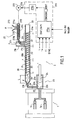
- FIG. 1 shows an installation allowing the manufacture of plastic preforms, from a polymer blend (P) / Additive (A), and comprising a multi-cavity mold 1, the inlet of which is connected to the output of an injection molding machine 2, described in detail below.
- the invention is obviously not limited to the manufacture of preforms plastics, but generally extends to the manufacture of all plastic part by injection into a mold of a mixture polymer (s) / additive (s).
- the mold 1 has two cavities 1 a, being specified that in practice a mold 1 could also include a single cavity 1 has or more commonly a greater number of cavities 1 a allowing the manufacture, at each injection cycle, of a plurality of preforms simultaneously.
- the injection press is a pot press injection, it being specified that a person skilled in the art can easily and immediately transpose the teaching of the description below to any other known type of injection press, and in particular a press direct injection in which the extrusion screw acts as a piston for injecting the material into the mold 1.
- the polymer P could be a mixture of several polymers, or that the injection molding machine could have several polymer gravity intake openings, each opening being dedicated to a given polymer.
- the additive applies to the additive.
- Polymer P consists of any type of polymer known thermoplastic or by any mixture of polymers known thermoplastics, which is capable of being transformed by plasticization in an injection molding machine of the type of FIG. 1, the most commonly used is PET.
- the polymer or polymer mixture P comes at the entrance of the injection molding machine in the form of granules or equivalents, which have preferably been previously dried and which are fed continuously and by gravity, for example from a dryer (not shown in the figures) connected to the inlet of the press inject.
- the temperature of the polymer P at the inlet of the injection molding machine is for example of the order from 140 ° C-150 ° C.
- Additive A is, in the illustrated embodiment, an additive in the form of solid granules, it being specified that in a way general, in the context of the invention, the additive may be only in granular form, but also in pulverulent, liquid, or semi-liquid (paste).
- This additive is for example, and in a non-exclusive and non-limiting manner of the invention, a dye food.
- the extrusion screw 20 is a screw endless equipped with F threads of constant diameter and carried by a body 20b.
- This body 20b consists of a first cylindrical rear portion intended to delimit, with the cylindrical wall of the sheath 21, a zone Z1 so-called feed, a median frustoconical part with increasing section intended to delimit, with the cylindrical wall of the sheath 21, a zone Z2 called compression, and a front cylindrical portion intended to delimit, with the cylindrical wall of the sleeve 21, a so-called transport zone Z3.
- the valve 26 is in the open position.
- Piston 24 is in position initial removed and delimits with the walls of the chamber 23a a volume (or in other words a predetermined quantity) of material to be injected into the mold at each injection cycle.
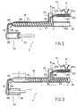
- the extrusion screw 20 is translated to force forward along its longitudinal axis 20a by the thrust member rear 22, into its position, known as the end of transfer, illustrated on the figure 2.
- the screw has thus been moved in translation over a distance substantially corresponding to the length L.
- the melted material (mixture polymer and additive melt A) present in space E is pushed by the extrusion screw 20 acting as a piston and is transferred to the connection conduit 25 and in the chamber 23a of the injection pot 23 which is thus filled with said molten mixture.
- the extrusion screw can simultaneously its forced translation, be rotated on itself or be motionless in rotation.
- the valve 26 is brought to the closed position, and insulates the sheath 21 of the injection pot 23.
- the extrusion screw 20 is rotated on itself along its axis 20a.
- the material (polymer mixture P / additive A) between the screw 20 and the sheath 21 is heated and kneaded, and progresses to gradually towards the front of the sleeve 21 towards the exit 21 b of the sleeve 21, while on the contrary the extrusion screw 20 moves backwards building on the material.
- the polymer P and the additive A melt under the effects combined mechanical shear forces between the sheath 21 and the screw 20, and heating by the heating sleeve 21, said polymer thus undergoing a plasticization and being intimately mixed with the additive A.
- the space E at the front of the extrusion screw 20 gradually increases in filling with melted material (polymer mixture P / additive A).
- the mold 1 is closed, and the piston 24 is pushed in. kind of injecting into the mold the amount of molten material (polymer P / additive A) contained in chamber 23a, then is drawn backwards sort of return to its original position, which determines the volume (quantity) of material injected in each cycle.
- the extrusion screw is stationary in translation and in rotation in its end-of-plasticization position in FIG. 1, awaiting the signal authorizing the start of the transfer phase.
- the duration of this third phase is short compared to the first two phases aforementioned transfer and plasticization.
- the threads F of the screw which are located to the right of the intake opening 21 a of the sleeve 21 are filled with a mixture of polymer and additive, only one small part of molten material progressing forward as of the withdrawal towards the rear of the extrusion screw 20, and being replaced by polymer and additive granules.
- the input rate of polymer by gravity in the plasticization phase is lower.
- the outlet pipe 274 aforementioned on the one hand is partly coaxial with a vertical conduit 21 c, which allows the gravity introduction of the polymer P at the inlet of the sleeve 21 of the extrusion screw 20, and on the other hand makes it possible to convey the additive A to the closer to the intake opening 21a of the sleeve 21.
- the motor 272 rotates the dosing screw 270 with a speed of rotation, which is automatically adjusted by the means 275 via control signal 276.
- Additive A is routed by this screw 270 to the outlet 271 b of the sleeve 271.
- the flow of additive A at the outlet of the sleeve 271 corresponds to the input flow rate of the additive into the sleeve 21 of the extrusion screw 20, and is directly proportional to the speed of rotation of the dosing screw 270.
- the invention is not limited to the implementation of a device for dosing with a dosing screw, but extends to any dosing device comprising a metering member equivalent to the dosing screw, and allowing to adjust automatically the feed rate of additive A at the inlet of the injection molding.
- the dosing device of Figure 1 is suitable for automatically add granular or powdery additive A, but is not on the other hand, it cannot be used to dose a liquid additive. So, and non-limiting manner of the invention, when the additive is in the form liquid, the metering device 27 of FIG. 1 is replaced by a dosing device based on the use of a peristaltic pump, a specific screw dosing pump for liquid or equivalent.
- the calculation module 275a is a programmed module, implemented for example, and in a limiting manner of the invention, in the form of a industrial programmable controller, or an electronic card specific comprising a programmed processing unit based on a microprocessor or microcontroller.
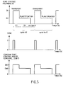
- this calculation module 275a is advantageously synchronized with the actual cycle of the injection molding machine 2, by a synchronization signal (SYNC), coming from the automation of injection press control.
- SYNC synchronization signal
- An example of a timing diagram for this synchronization signal (SYNC) is given in figure 5.
- the above parameters% A and QM are constants which are specific to the production.
- the Dv and Cr parameters are predetermined constants which characterize the injection molding machine.
- the parameter Bd is a specific constant of the polymer P to be injected. For example for PET, Bd is 0.8.
- control means 275 of the device dosage 27 will now be explained with reference to FIGS. 4 and 5.
- control means 275 advantageously allow to take into account the difference previously described between the inlet flow rate of polymer P into the screw of extrusion 20 in the transfer phase and the inlet flow rate of polymer P in the extrusion screw 20 in the plasticization phase, calculating automatically, for each new cycle, and from the parameters mentioned above, two additive input flow instructions DAT and DAP which are specific to the transfer phase and the phase of lamination.
- control means 275 More particularly, with reference to the flowchart of the figure 4, an example of operation of the control means 275 goes to present be described.
- the initial test 40 of the flow diagram of FIG. 4 makes it possible to synchronize the progress of the following stages with a change synchronization signal status (SYNC) characterizing the start of the transfer phase of a cycle (see also timing diagrams in the figure 5).
- SYNC change synchronization signal status
- the calculation module 275 triggers a time delay (step 41), the duration is equal to the aforementioned parameter TT (duration of the transfer phase) and delivers for the variable speed drive 275b (step 42) a setpoint of flow (CONSIGNMENT_DEBIT) which is equal to the variable DAT (setpoint of additive input flow in transfer phase); the current value of this variable DAT was previously calculated (during the third phase waiting for the previous cycle).
- the 275b variable speed drive controls the motor 272 of the dosing screw 270 with a speed (V1) allowing to obtain a real flow rate of additive A at the inlet of the extrusion screw 20 which is substantially equal to the calculated DAT flow setpoint.
- the calculation module 275 triggers a new time delay (step 44) whose duration is equal to the aforementioned parameter TP (duration of the plasticization phase) and delivers for the variable speed drive 275b (step 45) a flow instruction (CONSIGNE_DEBIT) which is equal to the DAP variable (additive input flow setpoint during plasticization); the current value of this DAP variable was previously calculated (during the third waiting phase of the cycle previous).
- variable speed drive 275b drives the motor 272 of the screw dosing 270 with a speed (V2) (which is lower than the above speed V1) making it possible to obtain a real additive flow rate, at the inlet of the screw extrusion 20, which is substantially equal to the calculated DAP setpoint.
- the DAT setpoint which is calculated for each cycle is greater than the DAP setpoint (additive input flow rate in the plasticization phase), said DAT and DAP instructions being calculated automatically so as to keep account for the difference in polymer input flow rate between the transfer (D1) and the plasticization phase (D2), and to obtain at the sleeve 21 of the extrusion screw 20 a concentration of additive in the polymer / additive mixture which is substantially constant over the entire cycle time.
- the calculation module 275 delivers for the variator speed 275b (step 45) a flow instruction (CONSIGNE_DEBIT) which is zero.
- the dosing screw 27 is stopped during this waiting phase.
- the calculation module 275 calculates (FIG. 4 / step 48) the DAT and DAP variables for the operating cycle next.
- the parameters TP and TT which are used by the calculation module 275a, can be predetermined constants.
- the variables TP and / or TT are preferably machine variables, which are automatically calculated at each cycle (in a manner known per se) and supplied to the calculation module 275 by the automation control of the injection press 2. For example, these variables are updated each time new cycle, based on their previous values on a number predetermined from previous cycles, and in particular by calculating the average of their values over a predetermined number of cycles precedents.
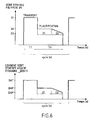
- the means of calculation 275a of the command means so that, from the moment where the compression zone Z2 of the screw 20 is located at the right of the opening intake 21 a of the sleeve 21, said calculation means 275a calculate a setpoint ("CONSIGNE_DEBIT") which decreases for example linearly in time from the current DAP value, according to a predetermined slope depending in particular on the taper of the area of compression Z2 of screw 20.
Abstract
Description
La présente invention concerne un perfectionnement apporté dans le domaine du dosage automatique d'un additif, tel que par exemple un colorant, à l'entrée d'une presse à injecter qui est alimentée par gravité avec au moins un matériau polymère sous forme de granulés. L'invention trouve avantageusement, mais non exclusivement, son application à la fabrication de préformes plastiques, notamment à base de PET (polyéthylène Téréphtalate) par injection dans un moule d'un mélange polymère/additif.The present invention relates to an improvement made in the field of automatic dosing of an additive, such as for example a dye, at the entrance of an injection molding machine which is fed by gravity with at least one polymer material in the form of granules. The invention advantageously, but not exclusively, finds its application to the manufacture of plastic preforms, in particular based on PET (polyethylene terephthalate) by injection into a mold of a mixture polymer / additive.
Pour fabriquer des pièces plastiques par injection d'un polymère ou d'un mélange de polymères dans un moule, on utilise une machine d'injection communément appelée presse à injecter, qui comporte une extrudeuse à vis, et dont la sortie (buse d'injection) est raccordée à l'entrée du moule. L'extrudeuse à vis comporte de manière usuelle au moins une vis sans fin dite vis d'extrusion, montée rotative sur elle-même à l'intérieur d'un fourreau chauffant, et équipée d'une part d'un organe moteur pour son entraínement en rotation sur elle-même, et d'autre part d'un organe de poussée, de type piston, pour son déplacement forcé en translation vers l'avant du fourreau, c'est-à-dire en direction de la sortie du fourreau.To make plastic parts by injecting a polymer or a mixture of polymers in a mold, we use a machine commonly known as an injection molding machine, which has a screw extruder, and whose outlet (injection nozzle) is connected to the entrance to the mold. The screw extruder usually comprises at minus a worm screw called extrusion screw, rotatably mounted on itself inside a heating sleeve, and equipped on the one hand with an organ motor for its rotational drive on itself, and on the other hand a thrust member, of the piston type, for its forced displacement in forward translation of the sheath, i.e. towards the exit scabbard.
Le fourreau de la vis d'extrusion est alimenté en continu, généralement par gravité, avec au moins un matériau polymère sous forme de granulés. L'introduction par gravité des granulés de polymère est réalisée en partie arrière du fourreau. Généralement, et en particulier pour les polymères tel que le PET qui sont facilement dégradables par hydrolyse en produisant des composés indésirables pour le produit final, tel que par exemple de l'acétaldéhyde (AA) dans le cas du PET, les granulés de polymère sont séchés avant introduction dans le fourreau de l'extrudeuse en étant par exemple chauffés dans une trémie de séchage amont dont la sortie est raccordée à l'entrée d'admission du fourreau de l'extrudeuse.The barrel of the extrusion screw is continuously supplied, generally by gravity, with at least one polymer material under form of granules. The gravity introduction of the polymer granules is made in the rear part of the sheath. Generally, and especially for polymers such as PET which are easily degradable by hydrolysis producing undesirable compounds for the final product, such as for example acetaldehyde (AA) in the case of PET, the polymer granules are dried before introduction into the sheath the extruder, for example by being heated in a drying hopper upstream whose outlet is connected to the inlet inlet of the barrel the extruder.
Il existe principalement deux types de presse à injecter : les presses à injecter avec pot d'injection ; les presses à injection directe, encore appelée machines réciproques.There are mainly two types of injection molding machines: injection molding machines with injection pot; direct injection presses, also called reciprocal machines.
Dans une presse à injecter avec pot d'injection, la sortie du fourreau de la vis d'extrusion est raccordée à l'entrée du pot d'injection par un conduit de raccordement équipé d'un organe de type vanne ou équivalent pour la fermeture/ouverture du conduit. Le pot d'injection est équipé d'un piston qui permet d'injecter dans le moule le matériau polymère fondu présent dans le pot d'injection. La presse à injecter fonctionne selon un cycle de fonctionnement répétitif comportant une phase dite de transfert suivie d'une phase dite de plastification :In an injection molding machine with injection pot, the outlet of the sleeve of the extrusion screw is connected to the inlet of the injection pot by a connection conduit fitted with a valve-type member, or equivalent for closing / opening the duct. The injection pot is equipped with a piston which allows the material to be injected into the mold molten polymer present in the injection pot. The injection molding machine operates on a repetitive operating cycle including a so-called transfer phase followed by a so-called plasticization phase:
Pendant cette phase, la vanne ou équivalent entre le fourreau de la vis d'extrusion et le pot d'injection est ouverte, la sortie du fourreau communiquant avec l'entrée du pot d'injection.During this phase, the valve or equivalent between the sheath of the extrusion screw and the injection pot is open, the outlet of the sleeve communicating with the inlet of the injection pot.
Cette phase de transfert se caractérise par un déplacement de la vis d'extrusion en translation vers l'avant et sous pression au moyen de l'organe de poussée de la vis. La matière présente dans le fourreau à l'avant de la tête de vis est ainsi poussée par la vis en direction de la sortie du fourreau et est transférée dans le conduit de raccordement et dans le pot d'injection.This transfer phase is characterized by a displacement of the extrusion screw in forward translation and under pressure by means of the screw thrust member. The material present in the sheath the front of the screw head is thus pushed by the screw towards the outlet of the sleeve and is transferred into the connection pipe and into the injection pot.
Selon le type de presse à injecter, pendant cette phase de transfert, la vis d'extrusion peut, simultanément à son déplacement forcé en translation par l'organe de poussée, être ou non entraínée en rotation sur elle-même. Depending on the type of injection molding machine, during this phase of transfer, the extrusion screw can, simultaneously with its forced displacement in translation by the thrust member, be or not driven in rotation on herself.
Pendant cette phase, la vanne ou équivalent entre le fourreau de la vis d'extrusion et le pot d'injection est fermée, la sortie du fourreau étant isolée de l'entrée du pot d'injection.During this phase, the valve or equivalent between the sheath of the extrusion screw and the injection pot is closed, the outlet of the sleeve being isolated from the inlet of the injection pot.
Cette phase de plastification se caractérise par un entraínement en rotation à vitesse contrôlée de la vis d'extrusion selon son axe longitudinal. Le matériau polymère présent dans le fourreau, sous les effets combinés de la température et du cisaillement mécanique de la matière entre la vis et le fourreau, passe progressivement, au fur et à mesure de son avancement dans le fourreau, de l'état solide (granulés) à l'état fondu en étant malaxé (plastification progressive du matériau polymère). Pendant cette phase de plastification, le matériau polymère qui est acheminé vers l'avant du fourreau repousse en translation vers l'arrière la vis d'extrusion (recul de la vis d'extrusion).This plasticization phase is characterized by training in controlled speed rotation of the extrusion screw along its axis longitudinal. The polymer material present in the sheath, under the combined effects of temperature and mechanical shear of the material between the screw and the sleeve, gradually passes, as and measurement of its progress in the sheath, from the solid state (granules) to the molten state by being kneaded (progressive plasticization of the material polymer). During this plasticization phase, the polymer material which is conveyed towards the front of the sheath pushes back in translation towards rear of the extrusion screw (recoil of the extrusion screw).
Il convient de noter que le matériau polymère n'est pas plastifié nécessairement uniquement au cours de la phase de plastification, mais que cette plastification peut dans certains cas se poursuivre également lors de la phase précitée de transfert.It should be noted that the polymer material is not plasticized necessarily only during the laminating phase but that this plasticization can in certain cases also continue during the aforementioned transfer phase.
L'injection du matériau polymère à l'état fondu présent dans le pot d'injection, au moyen du piston auxiliaire dont est équipé ledit pot, est réalisée en temps masqué pendant la phase de plastification, ce qui permet avantageusement d'obtenir des cycles de fonctionnement de faible durée et par là-même des cadences de production élevées et/ou de concevoir une machine dont la phase de plastification peut être plus longue et moins agressive, et/ou concevoir une machine avec une longueur de vis plus courte pour un débit de plastification identique.Injection of the polymer material in the molten state present in the pot injection, by means of the auxiliary piston with which said pot is fitted, is performed in masked time during the plasticization phase, which advantageously makes it possible to obtain low operating cycles duration and therefore high production rates and / or design a machine whose plasticization phase can be longer long and less aggressive, and / or design a machine with a shorter screw length for the same plasticizing flow.
Dans une presse à injection directe, la sortie du fourreau de l'extrudeuse est prévue pour être raccordée directement à l'entrée du moule d'injection. In a direct injection press, the outlet of the barrel the extruder is designed to be connected directly to the inlet of the injection mold.
La presse à injecter fonctionne ainsi selon un cycle de fonctionnement répétitif comportant une phase dite d'injection suivie d'une phase de plastification.The injection molding machine thus operates on a cycle of repetitive operation including a so-called injection phase followed a plasticization phase.
Pendant cette phase, la vis d'extrusion est poussée en translation vers l'avant sous pression au moyen de l'organe de poussée de la vis. La matière présente dans le fourreau à l'avant de la tête de vis est ainsi poussée par la vis en direction de la sortie du fourreau et est injectée directement dans le moule en sortie du fourreau.During this phase, the extrusion screw is pushed in translation forward under pressure by means of the screw thrust member. The material present in the sheath at the front of the screw head is thus pushed by the screw towards the outlet of the sleeve and is injected directly into the mold at the outlet of the sheath.
Cette phase est similaire à la phase de plastification précédemment décrite pour les presses à injecter avec pot d'injection.This phase is similar to the plasticization phase previously described for injection molding machines with injection pot.
De la même manière que pour les presses à injecter avec pot d'injection, le matériau polymère n'est pas plastifié nécessairement uniquement au cours de la phase de plastification, mais cette plastification peut dans certains cas se poursuivre également lors de la phase d'injection.In the same way as for injection molding machines with pot injection material, the polymer material is not necessarily plasticized only during the plasticization phase, but this plasticization may in some cases also continue during the phase injection.
A la différence des presses à injecter avec pot d'injection, dans les presses à injection directe, l'injection du matériau polymère fondu dans le moule est réalisée directement par la vis d'extrusion, lors de sa translation vers l'avant sous pression par l'organe de poussée, et non pas de manière séparée par un piston auxiliaire.Unlike injection molding machines with injection pot, in the direct injection presses, the injection of molten polymer material into the mold is produced directly by the extrusion screw, during its translation forward under pressure by the thrust member, not so separated by an auxiliary piston.
Dans le cas de presse à injection directe avec vis d'extrusion unique, on comprend que l'injection du polymère fondu dans le moule ne peut pas se faire en temps masqué pendant la phase de plastification. Pour pallier cet inconvénient, il est connu à ce jour d'utiliser des presses à injection directe à double vis d'extrusion. Dans ce cas, au cours d'un cycle de fonctionnement une des deux vis est isolée temporairement du moule et travaille en phase de plastification pendant que l'autre vis est raccordée au moule et travaille en phase d'injection ; au cycle suivant, le rôle des deux vis est inversé.In the case of a direct injection press with an extrusion screw unique, it is understood that the injection of the molten polymer into the mold does not cannot be done in masked time during the plasticization phase. To overcome this drawback, it is known to date to use presses direct injection with twin extrusion screws. In this case, during a cycle one of the two screws is temporarily isolated from the mold and works in the plasticization phase while the other screw is connected in the mold and works during the injection phase; in the next cycle, the role of two screws is reversed.
L'invention peut être appliquée à tout type connu de presse à injecter avec vis d'extrusion, et notamment aussi bien aux presses à injecter avec pot et piston auxiliaire d'injection, qu'aux presses à injection directe.The invention can be applied to any known type of press inject with extrusion screw, and in particular as well with inject with pot and auxiliary injection piston, only with injection presses direct.
Par soucis de simplification, dans la suite de la présente, les termes « phase de transfert » désigneront indifféremment non seulement la phase de transfert précédemment décrite d'un cycle d'une presse à injecter avec pot d'injection, mais également la phase d'injection d'une presse à injection directe, c'est-à-dire d'une manière plus générale la phase au cours de laquelle la vis d'extrusion est poussée en translation à force vers l'avant.For the sake of simplification, hereinafter, the "transfer phase" will mean not only the previously described transfer phase of a press press cycle inject with injection pot, but also the injection phase of a direct injection press, that is to say more generally the phase during which the extrusion screw is pushed in translation at force forward.
Les termes « phase de plastification » désigneront d'une manière générale la phase au cours de laquelle la vis d'extrusion est entraínée uniquement en rotation et se déplace en translation vers l'arrière, et couvre ainsi la phase précitée de plastification d'un cycle d'une presse à injecter avec pot d'injection ou d'un cycle d'une presse à injection directe.The terms "plasticization phase" will mean in a way general the phase during which the extrusion screw is driven only in rotation and moves in translation backwards, and thus covers the aforementioned phase of plasticization of a cycle of a press inject with injection pot or cycle of a direct injection press.
Dans l'industrie de l'injection moulage, et notamment dans le domaine de la fabrication de préformes plastiques, qui sont des produits intermédiaires et sont destinées ultérieurement à être étirées et soufflées dans un moule pour former des bouteilles plastiques (produits finaux), il est courant de fabriquer des pièces plastiques colorées. La coloration des pièces est réalisée en ajoutant un colorant au polymère. Ce colorant peut être de type solide (poudre ou granulés) ou de type liquide.In the injection molding industry, and in particular in the manufacturing of plastic preforms, which are products intermediate and are later intended to be stretched and blown in a mold to form plastic bottles (final products), is common to make colored plastic parts. The coloring of parts is made by adding a dye to the polymer. This dye can be of the solid type (powder or granules) or of the liquid type.
Plus généralement, dans le but de conférer des propriétés particulières au produit final, il est fréquent d'ajouter au polymère des additifs, selon le cas sous forme liquide ou solide, qui ne sont pas nécessairement des colorants. Par exemple dans le domaine de la fabrication de préformes, il est courant d'ajouter comme additifs : additif réducteur d'acétaldéhyde, agent glissant ( « slip agent »), additif pour le blocage des rayons UV (« UV blocker »), additif permettant d'accélérer le chauffage par infra-rouge, agent gonflant ( « foaming agent »), charges diverses, par exemple pour diminuer le coût matière ( talc, carbonate de calcium, ...), additif permettant de réduire la charge électrostatique du produit final, etc...More generally, in order to confer properties specific to the final product, it is common to add to the polymer additives, as the case may be in liquid or solid form, which are not necessarily dyes. For example in the field of manufacturing of preforms, it is common to add as additives: additive acetaldehyde reducer, slip agent, additive for blocking UV rays ("UV blocker"), an additive to accelerate the infrared heating, foaming agent, fillers various, for example to reduce the material cost (talc, carbonate of calcium, ...), additive to reduce the electrostatic charge of end product, etc ...
L'ajout d'additif est réalisé en introduisant l'additif dans le fourreau de la vis d'extrusion généralement par la même ouverture d'admission que le polymère.Addition of additive is carried out by introducing the additive into the sheath of the extrusion screw generally through the same intake opening as the polymer.
La quantité d'additif ajoutée par unité de temps (Débit d'additif) est également contrôlée automatiquement au moyen d'un dispositif de dosage. Ce dispositif de dosage comporte par exemple une pompe d'alimentation péristaltique ou équivalent dans le cas d'un additif liquide, ou une vis de dosage ou équivalent dans le cas d'un additif sous forme de granulés ou de produit pulvérulent.The amount of additive added per unit of time (Additive flow) is also automatically controlled by means of a dosage. This metering device comprises for example a pump peristaltic feed or equivalent in the case of a liquid additive, or a dosing screw or equivalent in the case of an additive in the form of granules or powdery product.
L'organe de dosage ( pompe, vis, ...) du dispositif de dosage est commandé automatiquement par des moyens de commande, en fonction notamment d'une consigne prédéterminée, qui est calculée par l'opérateur de la presse à injecter. Cette consigne dépend de la quantité totale d'additif nécessaire par cycle en fonction de la quantité moyenne de polymère utilisée à chaque cycle pour mouler un ou plusieurs produits et de la concentration d'additif recherchée dans chaque produit final moulé. S'agissant plus particulièrement d'un dispositif de dosage à vis, cette consigne est par exemple la vitesse de rotation de la vis de dosage. Cette consigne et la durée estimée d'un cycle sont entrées dans le dispositif de dosage comme paramètres de fonctionnement des moyens de commande électroniques du dispositif de dosage.The metering device (pump, screw, ...) of the metering device is automatically controlled by control means, depending in particular a predetermined setpoint, which is calculated by the operator of the injection molding machine. This deposit depends on the total quantity of additive required per cycle depending on the average amount of polymer used in each cycle to mold one or more products and the concentration of additive sought in each molded final product. Being more particularly a screw metering device, this setpoint is for example the speed of rotation of the dosing screw. This setpoint and the estimated duration of a cycle are entered into the dosing as operating parameters of the control means dosing device electronics.
D'une manière générale, pendant chaque cycle de fonctionnement de la presse à injecter (phase de transfert/phase de plastification), les moyens de commande pilotent automatiquement l'organe de dosage à partir notamment de la consigne précitée, laquelle consigne est identique et constante pour les phases de transfert et de plastification d'un cycle. Eventuellement, dans des solutions plus sophistiquées, les moyens de commande peuvent également être conçus pour tenir compte du fonctionnement réel de la vis d'extrusion, en commandant l'organe de dosage en fonction d'une durée de cycle qui n'est pas une constante prédéterminée, mais qui est une variable calculée à chaque cycle, à partir de la durée réelle mesurée de cycles précédents.Generally, during each operating cycle of the injection molding machine (transfer phase / plasticization phase), the control means automatically control the metering member to in particular starting from the aforementioned instruction, which instruction is identical and constant for the transfer and plasticization phases of a cycle. Possibly, in more sophisticated solutions, the means of control can also be designed to account for actual operation of the extrusion screw, by controlling the dosing according to a cycle time which is not a constant predetermined, but which is a variable calculated in each cycle, from the actual measured duration of previous cycles.
En mettant en oeuvre les solutions précitées de dosage de l'art antérieur, on constate en pratique que la concentration en additif n'est pas constante dans tout le produit final moulé, ce qui est préjudiciable à la qualité du produit. Dans le cas d'un colorant, ce défaut d'uniformité peut se traduire par exemple par des défauts visuels de coloration qui peuvent être perceptibles à l'oeil.By implementing the aforementioned art dosage solutions previous, it is found in practice that the additive concentration is not constant throughout the final molded product, which is detrimental to the product quality. In the case of a dye, this lack of uniformity can result for example in visual defects in coloring which may be perceptible to the eye.
Egalement, on constate à l'usage, en particulier dans le cas d'utilisation d'additifs liquides, que la vis d'extrusion a tendance à patiner en phase de plastification, ce qui se traduit par une augmentation qui peut être préjudiciable pour le polymère de la durée de la phase de plastification, voire dans certain cas par un blocage du fonctionnement de la vis d'extrusion nécessitant d'intervenir sur la presse à injecter. Ce défaut s'explique par le fait que l'additif introduit dans la vis d'extrusion, lorsqu'il est localement en excès par rapport à la quantité de polymère, modifie localement dans la vis et de manière trop importante les propriétés rhéologiques, et notamment la viscosité, du matériau en cours de plastification.Also, we see in use, especially in the case use of liquid additives, which the extrusion screw tends to slip in the plasticization phase, which results in an increase which can be detrimental to the polymer from the duration of the plasticization, or even in some cases by blocking the operation of the extrusion screw requiring intervention on the injection molding machine. This defect is explained by the fact that the additive introduced into the extrusion screw, when it is locally in excess relative to the amount of polymer, locally modifies the properties of the screw too much rheological, and in particular the viscosity, of the material being lamination.
Dans le but de pallier ces problèmes, on a déjà proposé de réaliser un pré-mélange additif/ polymère à l'extérieur du fourreau de la vis d'extrusion, au moyen notamment d'un dispositif mélangeur à pales rotatives monté sur le fourreau de la vis d'extrusion. In order to overcome these problems, it has already been proposed to perform an additive / polymer premix on the outside of the screw sleeve extrusion, in particular by means of a paddle mixer device rotary mounted on the sleeve of the extrusion screw.
Cette solution présente toutefois plusieurs inconvénients majeurs.However, this solution has several major drawbacks.
Un premier inconvénient est une baisse sensible (en pratique d'une ou plusieurs dizaines de degrés Celsius) de la température du polymère à l'entrée du fourreau de la vis d'extrusion. Cet abaissement de température est d'une manière générale préjudiciable pour le processus de plastification du polymère. Il oblige notamment à augmenter la température de chauffage du fourreau de la vis d'extrusion, ce qui est préjudiciable pour la transformation du polymère. En particulier, dans le cas d'un polymère de type PET, l'augmentation de la température de chauffage de la vis augmente les risques de production de produits secondaires issus de la dégradation du polymère, tel que l'acétaldéhyde. Egalement, l'augmentation de la température de chauffage du fourreau de la vis d'extrusion constitue une perte d'un point de vue énergétique et augmente par là-même les coûts de fabrication.A first drawback is a significant drop (in practice one or more tens of degrees Celsius) of the temperature of the polymer at the inlet of the barrel of the extrusion screw. This lowering of temperature is generally detrimental to the process plasticizing the polymer. In particular, it requires increasing the heating temperature of the barrel of the extrusion screw, which is detrimental to the transformation of the polymer. In particular, in the case of a PET type polymer, increasing the temperature of screw heating increases the risk of product production secondary from degradation of the polymer, such as acetaldehyde. Also, the increase in the heating temperature of the barrel of the extrusion screw constitutes a loss from an energy point of view and thereby increases manufacturing costs.
Un deuxième inconvénient est une génération préjudiciable de poussières, due à l'abrasion des granulés ente eux dans le mélangeur.A second disadvantage is a damaging generation of dust, due to abrasion of the granules ente them in the mixer.
Un troisième inconvénient réside dans la contrainte et la difficulté de nettoyage du mélangeur, en particulier lors d'un changement d'additif.A third disadvantage lies in the constraint and the difficulty cleaning the mixer, especially when changing the additive.
L'objectif principal de l'invention est de proposer une nouvelle solution aux problèmes précités de défaut d'homogénéité de la quantité d'additif dans le produit moulé et de patinage de la vis d'extrusion de la presse à injecter, c'est-à-dire une solution qui permet d'obtenir une concentration en additif plus homogène dans tout le produit final et qui diminue les risques de patinage de la vis. Cette solution doit également permettre de s'affranchir des inconvénients précités inhérents à la solution de l'art antérieur avec mélangeur (pré-mélange additif/polymère), et en particulier doit éviter un abaissement préjudiciable de la température du polymère à l'entrée de la vis d'extrusion. The main objective of the invention is to propose a new solution to the aforementioned problems of lack of uniformity of quantity of additive in the molded product and slip of the extrusion screw of the injection molding machine, that is to say a solution which makes it possible to obtain a more homogeneous additive concentration throughout the final product and which reduces the risk of the screw slipping. This solution should also to overcome the aforementioned drawbacks inherent in the solution of the prior art with mixer (additive / polymer premix), and particular should avoid a detrimental lowering of the temperature of the polymer at the entrance of the extrusion screw.
L'objectif précité est atteint au moyen d'un nouveau procédé de dosage d'au moins un additif à l'entrée d'une presse à injecter comportant une vis d'extrusion qui est alimentée en continu et par gravité avec au moins un polymère sous forme de granulés, et qui fonctionne selon un cycle de fonctionnement répétitif comportant une première phase dite de transfert au cours de laquelle la vis d'extrusion est déplacée en translation vers l'avant, suivie d'une deuxième phase dite de plastification au cours de laquelle la vis d'extrusion est entraínée uniquement en rotation et se déplace en translation vers l'arrière.The aforementioned objective is achieved by means of a new method of dosing of at least one additive at the inlet of an injection molding machine comprising an extrusion screw which is fed continuously and by gravity with at minus a polymer in the form of granules, and which functions according to a repetitive operating cycle comprising a first phase called transfer during which the extrusion screw is moved in translation forward, followed by a second phase called plasticization during which the extrusion screw is driven only in rotation and is moves in translation backwards.
De manière caractéristique et nouvelle selon l'invention, l'additif (A) à doser étant introduit à l'intérieur du fourreau de la vis d'extrusion de la presse à injecter en même temps que le polymère (P), dans le but de tenir compte de la différence entre le débit réel d'entrée du polymère (P) en phase de transfert et le débit réel d'entrée du polymère (P) en phase de plastification, on introduit l'additif (A) à l'entrée de la vis d'extrusion avec un débit d'entrée d'additif au cours de la phase de transfert qui est différent du débit d'entrée d'additif au cours de la phase de plastification.Characteristically and novel according to the invention, the additive (A) to be dosed being introduced inside the sheath of the extrusion screw the injection molding machine at the same time as the polymer (P), in order to take into account the difference between the actual polymer input flow (P) in the transfer phase and the actual polymer input flow rate (P) in the phase plasticization, additive (A) is introduced at the inlet of the extrusion screw with an additive input flow during the transfer phase which is different from the additive input flow rate during the plasticization phase.
L'invention a également pour autres objets un dispositif de dosage automatique d'au moins un additif à l'entrée d'une presse à injecter, une presse à injecter équipée d'un tel dispositif de dosage, et une machine de production d'articles plastiques, et notamment de préformes plastiques, comportant ladite presse à injecter raccordée à un moule d'injection.The invention also has for other objects a metering device automatic of at least one additive at the entry of an injection molding machine, a injection molding machine equipped with such a metering device, and a production of plastic articles, and in particular plastic preforms, comprising said injection press connected to an injection mold.
Le dispositif de dosage de l'invention est connu en ce qu'il comporte un organe de dosage piloté par des moyens de commande en sorte de régler automatiquement le débit d'introduction de l'additif à partir d'une consigne prédéterminée, dite consigne de débit d'entrée d'additif.The metering device of the invention is known in that it comprises a metering member controlled by control means in sort of automatically adjusting the rate of introduction of the additive from a predetermined setpoint, called the additive input flow rate setpoint.
De manière caractéristique selon l'invention, les moyens de commande pilotent l'organe de dosage en fonction d'au moins deux consignes de débit d'entrée d'additif distinctes : au moins une consigne de débit d'entrée d'additif (DAT) spécifique pour la phase de transfert de la presse à injecter, et au moins une deuxième consigne de débit d'entrée d'additif (DAP) spécifique pour la phase de plastification de la presse à injecter.Typically according to the invention, the means of control control the metering device based on at least two separate additive input flow setpoints: at least one setpoint Specific additive input rate (DAT) for the transfer phase of the injection molding machine, and at least a second input flow setpoint specific additive (DAP) for the plasticization phase of the inject.
Jusqu'à présent, à la connaissance de la demanderesse, toutes les solutions connues de dosage de l'art antérieure reposent sur l'hypothèse que le débit de polymère introduit par gravité à l'entrée de la vis d'extrusion est sensiblement constant pendant toute la durée des phases de transfert et de plastification d'un cycle.To date, to the knowledge of the plaintiff, all known dosing solutions of the prior art are based on the assumption that the flow of polymer introduced by gravity at the inlet of the extrusion screw is substantially constant throughout the duration of the transfer and plasticization phases of a cycle.
L'invention est basée et découle du constat nouveau qui a été fait que ce débit d'entrée de polymère n'est pas sensiblement constant au cours d'un cycle, mais varie de manière importante entre la phase de transfert et la phase de plastification. Les procédés et dispositif de dosage précités de l'invention permettent ainsi avantageusement de tenir compte de cette différence de débit d'entrée de polymère entre les phases de transfert et de plastification d'un cycle.The invention is based and follows from the new observation that has been made that this polymer input flow rate is not substantially constant at during a cycle, but varies significantly between the phase of transfer and plasticization phase. Dosage methods and device mentioned above of the invention thus advantageously take into account of this difference in polymer inlet flow between the phases of transfer and plasticization of a cycle.
A posteriori, cette différence de débit d'entrée de polymère entre les phases de transfert et de plastification d'un cycle peut s'expliquer par la combinaison des deux facteurs suivants.A posteriori, this difference in polymer input flow rate between the transfer and plasticization phases of a cycle can be explained by the combination of the following two factors.
Au cours de la phase de plastification, les filets de la vis lorsqu'ils arrivent à l'aplomb de l'ouverture d'admission du polymère sont au moins partiellement remplis de polymère, et la quantité de polymère introduite entre chaque filet permet uniquement de compenser la quantité (faible) de polymère fondu qui quitte le filet en progressant vers l'avant de la vis. Une fois la vis en position arrière (fin de la phase de plastification) les filets de la vis qui sont situés en arrière de l'ouverture d'admission par gravité du polymère sont en revanche vides. Ainsi (premier facteur), lorsque la vis est poussée en avant au cours de la phase de transfert, ces filets vides, lorsqu'ils se trouvent à l'aplomb de l'ouverture d'admission, offrent un volume de remplissage plus important susceptible de recevoir par gravité une quantité donnée de polymère qui est plus importante que celle servant à compenser l'avancement du polymère en phase de plastification.During the laminating phase, the threads of the screw when they are plumb with the polymer inlet opening are at least partially filled with polymer, and the quantity of polymer introduced between each net only compensates for the (small) amount of molten polymer which leaves the thread progressing towards the front of the screw. A once the screw in rear position (end of the plasticization phase) the threads the screw which are located behind the gravity intake opening of the polymer are empty. So (first factor), when the screw is thrust forward during the transfer phase, these empty nets, when they are level with the intake opening, offer a larger filling volume likely to receive by gravity a given quantity of polymer which is greater than that used to compensate for the advancement of the polymer in the lamination.
Egalement (deuxième facteur), les vitesses de translation de la vis d'extrusion sont généralement différentes entre la phase de plastification et la phase de transfert. En phase de plastification, la vitesse de recul de la vis d'extrusion dépend notamment des caractéristiques rhéologiques du polymère utilisé, qui permettent sa plastification, c'est-à-dire son passage de l'état de granulés cristallins solides à l'état de polymère fondu amorphe. En phase de transfert, cette vitesse de translation est déterminée en sorte d'obtenir généralement une durée de la phase de transfert qui soit courte, et de préférence la plus courte possible, sans qu'il y ait une détérioration des propriétés du polymère en phase transfert.Also (second factor), the translation speeds of the screw are generally different between the plasticization phase and the transfer phase. In the plasticization phase, the speed of recoil the extrusion screw depends in particular on the rheological characteristics of the polymer used, which allow its plasticization, that is to say its passage from the state of solid crystalline granules to the state of amorphous molten polymer. In the transfer phase, this translation speed is determined so generally obtain a short duration of the transfer phase, and preferably as short as possible, without any deterioration properties of the polymer in the transfer phase.
Dans la plupart des cas, la vitesse de translation en phase transfert de la vis d'extrusion est supérieure à la vitesse de translation de la vis en phase de plastification, ce qui correspond à une durée de la phase de transfert qui est inférieure à la durée de la phase de plastification. La combinaison des deux facteurs précités aboutit ainsi en pratique à une augmentation sensible du débit d'entrée polymère en phase de transfert, par rapport au débit d'entrée polymère en phase de plastification. Dans ce cas, le procédé de dosage de l'invention se caractérise plus particulièrement par un débit d'entrée d'additif au cours de la phase de transfert qui est supérieur au débit d'entrée d'additif au cours de la phase de plastification.In most cases, the phase translation speed transfer of the extrusion screw is greater than the translation speed of the screw in the plasticization phase, which corresponds to a duration of the transfer phase which is less than the duration of the lamination. The combination of the two aforementioned factors thus results in practical for a significant increase in the polymer input flow in transfer phase, relative to the polymer input flow rate in the lamination. In this case, the assay method of the invention is more particularly characterized by an additive input flow rate during the transfer phase which is greater than the additive input flow rate during of the plasticization phase.
Il peut néanmoins arriver dans certains cas que la vitesse de translation en phase transfert de la vis d'extrusion soit inférieure à la vitesse de translation de la vis en phase de plastification, et soit suffisamment faible pour que finalement le débit d'entrée polymère en phase de transfert soit inférieur au débit d'entrée polymère en phase de plastification, et ce malgré le premier facteur précité. Dans ce cas particulier de fonctionnement, le procédé de dosage de l'invention se caractérise plus particulièrement par un débit d'entrée d'additif au cours de la phase de transfert qui est inférieur au débit d'entrée d'additif au cours de la phase de plastification.It may however happen in certain cases that the speed of translation in transfer phase of the extrusion screw is less than the translation speed of the screw during the plasticization phase, and either low enough that finally the polymer input flow in transfer phase is lower than the polymer input flow rate in the plasticization, despite the first factor mentioned above. In that case particular operation, the metering method of the invention is more particularly characterized by an additive input flow rate during the transfer phase which is lower than the additive input flow rate during of the plasticization phase.
Dans une mise en oeuvre simplifiée de l'invention, chaque consigne de débit d'entrée d'additif pour la phase de transfert et chaque consigne de débit d'entrée d'additif pour la phase de plastification pourraient être déterminées par l'utilisateur de la presse à injecter et entrées comme paramètres. Dans une réalisation préférée de l'invention les consignes de débit d'entrée d'additif sont calculées automatiquement à chaque cycle de fonctionnement, en fonction notamment de paramètres réels de structure et fonctionnement de la presse à injecter.In a simplified implementation of the invention, each additive input flow setpoint for the transfer phase and each additive input flow set point for the plasticization phase could be determined by the user of the injection molding machine and entries as parameters. In a preferred embodiment of the invention the additive input flow setpoints are calculated automatically at each operating cycle, depending in particular on parameters structure and operation of the injection molding machine.
D'autres caractéristiques et avantages de l'invention apparaítront plus clairement ci-après à la lecture de la description suivante d'un exemple préféré de réalisation de l'invention, laquelle description est donnée à titre d'exemple non limitatif et non exhaustif, et en référence aux dessins annexés sur lesquels :
- la figure 1 est une représentation schématique d'une installation de fabrication de préformes comportant une presse à injecter équipée d'un dispositif de dosage d'additif conforme à l'invention, la vis d'extrusion de la presse étant dans sa position de début de phase de transfert (ou de fin de phase de plastification),
- la figure 2 représente la presse à injecter de la figure 1, avec la vis d'extrusion dans sa position de fin de phase de transfert,
- la figure 3 représente une variante de presse à injecter, dont la vis d'extrusion est dans sa position de début de phase de transfert (ou fin de phase de plastification), position de la vis dans laquelle la zone de compression de la vis arrive au droit de l'ouverture d'admission du polymère et de l'additif,
- la figure 4 est un organigramme représentant les principales étapes de fonctionnement des moyens de commande pilotant le dispositif de dosage de l'installation de la figure 1,
- la figure 5 représente des exemples de chronogrammes des principales grandeurs (débit d'entrée polymère / consigne de débit d'entrée additif) et du signal de synchronisation utilisé pour synchroniser les moyens de commande du dispositif de dosage,
- la figure 6 représente des exemples de chronogrammes des principales grandeurs (débit d'entrée polymère / consigne de débit d'entrée additif) dans le cas particulier de la presse à injecter de la figure 3.
- Figure 1 is a schematic representation of a preform manufacturing installation comprising an injection molding machine equipped with an additive metering device according to the invention, the press extrusion screw being in its start position transfer phase (or end of plasticization phase),
- FIG. 2 represents the injection molding machine of FIG. 1, with the extrusion screw in its position at the end of the transfer phase,
- FIG. 3 represents a variant of an injection molding machine, the extrusion screw of which is in its position at the start of the transfer phase (or end of the plasticization phase), position of the screw in which the compression zone of the screw arrives on the right of the polymer and additive intake opening,
- FIG. 4 is a flow diagram representing the main stages of operation of the control means controlling the metering device of the installation of FIG. 1,
- FIG. 5 represents examples of chronograms of the main quantities (polymer input flow / additive input flow setpoint) and of the synchronization signal used to synchronize the control means of the metering device,
- FIG. 6 represents examples of chronograms of the main quantities (polymer input flow / additive input flow setpoint) in the particular case of the injection press of FIG. 3.
On a représenté sur la figure 1 une installation permettant la
fabrication de préformes plastiques, à partir d'un mélange polymère
(P)/Additif (A), et comportant un moule 1 multi-cavités, dont l'entrée est
raccordée à la sortie d'une presse à injecter 2, décrite en détail ci-après.
L'invention n'est bien évidemment pas limitée à la fabrication de préformes
plastiques, mais s'étend d'une manière générale à la fabrication de toute
pièce en plastique par injection dans un moule d'un mélange
polymère(s)/additif(s).FIG. 1 shows an installation allowing the
manufacture of plastic preforms, from a polymer blend
(P) / Additive (A), and comprising a
Dans l'exemple illustré le moule 1 comporte deux cavités 1 a, étant
précisé qu'en pratique un moule 1 pourrait également comporter une
seule cavité 1 a ou de manière plus courante un nombre plus important de
cavités 1 a permettant la fabrication, à chaque cycle d'injection, d'une
pluralité de préformes simultanément.In the example illustrated, the
Dans l'exemple illustré, la presse à injecter est une presse à pot
d'injection, étant précisé que l'homme du métier pourra aisément et
immédiatement transposer l'enseignement de la description ci-après à tout
autre type connu de presse à injecter, et en particulier à une presse à
injection directe dans laquelle la vis d'extrusion fait office de piston pour
l'injection de la matière dans le moule 1.In the example illustrated, the injection press is a pot press
injection, it being specified that a person skilled in the art can easily and
immediately transpose the teaching of the description below to any
other known type of injection press, and in particular a press
direct injection in which the extrusion screw acts as a piston for
injecting the material into the
Egalement, dans l'exemple illustré et dans la description ci-après de cet exemple, il est considéré que l'on introduit à l'entrée de la presse à injecter un unique polymère P, étant précisé que dans d'autres réalisations conformes à l'invention, le polymère P pourrait être un mélange de plusieurs polymères, ou que la presse à injecter pourrait comporter plusieurs ouvertures d'admission par gravité de polymères, chaque ouverture étant dédiée à un polymère donné. Les mêmes remarques s'appliquent à l'additif.Also, in the example illustrated and in the description below of this example it is considered that one introduces at the entrance of the press to inject a single polymer P, it being specified that in other embodiments in accordance with the invention, the polymer P could be a mixture of several polymers, or that the injection molding machine could have several polymer gravity intake openings, each opening being dedicated to a given polymer. The same remarks apply to the additive.
Le polymère P est constitué par tout type de polymère thermoplastique connu ou par tout mélange de polymères thermoplastiques connus, qui est apte à être transformé par plastification dans une presse à injecter du type de la figure 1, le polymère le plus couramment utilisé étant le PET. Le polymère ou mélange de polymère P se présente à l'entrée de la presse à injecter sous la forme de granulés ou équivalents, qui ont de préférence été préalablement séchés et qui sont alimentés en continu et par gravité, par exemple en étant issus d'un sécheur (non représenté sur les figures) raccordé à l'entrée de la presse à injecter. A titre d'exemple, s'agissant de granulés de PET, la température du polymère P à l'entrée de la presse à injecter est par exemple de l'ordre de 140°C-150°C.Polymer P consists of any type of polymer known thermoplastic or by any mixture of polymers known thermoplastics, which is capable of being transformed by plasticization in an injection molding machine of the type of FIG. 1, the most commonly used is PET. The polymer or polymer mixture P comes at the entrance of the injection molding machine in the form of granules or equivalents, which have preferably been previously dried and which are fed continuously and by gravity, for example from a dryer (not shown in the figures) connected to the inlet of the press inject. For example, in the case of PET granules, the temperature of the polymer P at the inlet of the injection molding machine is for example of the order from 140 ° C-150 ° C.
L'additif A est, dans l'exemple de réalisation illustré, un additif sous forme de granulés solides, étant précisé que d'une manière générale, dans le cadre de l'invention, l'additif pourra se présenter non seulement sous forme granulaire, mais également sous forme pulvérulente, liquide, ou semi liquide (pâte). Cet additif est par exemple, et de manière non exclusive et non limitative de l'invention, un colorant alimentaire. Additive A is, in the illustrated embodiment, an additive in the form of solid granules, it being specified that in a way general, in the context of the invention, the additive may be only in granular form, but also in pulverulent, liquid, or semi-liquid (paste). This additive is for example, and in a non-exclusive and non-limiting manner of the invention, a dye food.
En référence à la figure 1, la presse à injecter 2 comporte de manière connue en soi :
- une vis d'extrusion 20 montée rotative dans un fourreau chauffant 21, et équipée en partie arrière d'un moteur (non visible sur les figures) pour son entraínement en rotation sur elle-même selon son axe central longitudinal 20a ; le fourreau 21 comporte au niveau de sa zone arrière une ouverture 21 a pour l'admission du polymère P et de l'additif A, et à son extrémité avant une ouverture d'évacuation 21 b permettant le transfert du mélange fondu polymère P / additif A ;
- un organe de poussée 22, type piston hydraulique ou équivalent, qui est prévu pour exercer sur la partie arrière de la vis d'extrusion 20 une force de poussé suffisante pour translater la vis vers l'avant du fourreau 21 (ce qui correspond à la phase de transfert ci-après), de telle sorte que la vis arrive par exemple dans la position de fin de transfert illustrée sur la figure 2;
un pot d'injection 23 qui délimite une chambre 23a de réception d'une quantité mesurée de mélange fondu polymère P/additif A, et qui est équipé d'unpiston d'injection 24 ;ladite chambre 23a comporte en partie supérieure une ouverture d'admission 23b et à l'opposé dupiston 24une ouverture d'évacuation 23c qui est raccordée directement à l'entrée du moule 1 ;- un conduit court de raccordement 25 reliant
la sortie 21 a du fourreau 21 à l'ouverture d'admission 23b de la chambre 23a dupot d'injection 23, lequelconduit 25 est équipé d'une vanne de fermeture 26; - un dispositif de
dosage 27 permettant d'alimenter et de doser l'additif A à l'entrée du fourreau 21.
- an
extrusion screw 20 rotatably mounted in aheating sleeve 21, and equipped in the rear part with a motor (not visible in the figures) for its rotational drive on itself along its longitudinalcentral axis 20a; thesheath 21 has at its rear zone anopening 21 a for the admission of the polymer P and of the additive A, and at its front end adischarge opening 21 b allowing the transfer of the melted polymer P / additive mixture AT ; - a
thrust member 22, of the hydraulic piston type or equivalent, which is designed to exert on the rear part of theextrusion screw 20 a pushing force sufficient to translate the screw towards the front of the sleeve 21 (which corresponds to the transfer phase below), so that the screw arrives for example in the end of transfer position illustrated in FIG. 2; - an
injection pot 23 which delimits achamber 23a for receiving a measured quantity of molten polymer P / additive A mixture, and which is equipped with aninjection piston 24; saidchamber 23a comprises in the upper part aninlet opening 23b and opposite thepiston 24 anoutlet opening 23c which is connected directly to the inlet of themold 1; - a
short connection conduit 25 connecting theoutlet 21a of thesleeve 21 to the inlet opening 23b of thechamber 23a of theinjection pot 23, whichconduit 25 is equipped with a closingvalve 26; - a
metering device 27 enabling the additive A to be fed and metered at the inlet of thesleeve 21.
De manière usuelle également, la vis d'extrusion 20 est une vis
sans fin équipée de filets F de diamètre constant et portés par un corps
20b. Ce corps 20b est constitué d'une première portion arrière cylindrique
destinée à délimiter, avec la paroi cylindrique du fourreau 21, une zone Z1
dite d'alimentation, une partie tronconique médiane à section croissante
destinée à délimiter, avec la paroi cylindrique du fourreau 21, une zone Z2
dite de compression, et une portion cylindrique avant destinée à délimiter,
avec la paroi cylindrique du fourreau 21, une zone Z3 dite de transport.Also usually, the
La commande de l'organe de poussée 22 de la vis d'extrusion 20,
du moteur permettant l'entraínement en rotation de la vis d'extrusion 20,
du piston d'injection 24, et de la vanne 26, est de manière connue en soi
assurée de manière automatique par automatisme de commande
(automate programmable ou équivalent non représenté) permettant le
fonctionnement cyclique de la presse à injecter qui va à présent être décrit
en référence aux figures 1 et 2.The control of the
On considère qu'au début d'un cycle de fonctionnement, la vis
d'extrusion 20 se trouve dans la position axiale de retrait illustrée sur la
figure 1 (position retirée vers l'arrière), un espace E de longueur L étant
ménagé dans le fourreau 21 entre l'extrémité avant de la vis 20 et
l'ouverture d'évacuation 21 b du fourreau 21, du fait du retrait de la vis. Un
cycle de fonctionnement de la presse à injecter est constitué des trois
phases successives ci-après.It is considered that at the start of an operating cycle, the
La vanne 26 est en position ouverte. Le piston 24 est en position
initiale retirée et délimite avec les parois de la chambre 23a un volume (ou
en d'autres termes une quantité) prédéterminée de matière à injecter dans
le moule à chaque cycle d'injection. La vis d'extrusion 20 est translatée à
force vers l'avant selon son axe longitudinal 20a par l'organe de poussée
arrière 22, jusque dans sa position, dite de fin de transfert, illustrée sur la
figure 2. La vis a ainsi été déplacée en translation sur une distance
correspondant sensiblement à la longueur L. La matière fondue (mélange
fondu de polymère et d'additif A) présente dans l'espace E est poussée
par la vis d'extrusion 20 agissant comme un piston et est transférée dans
le conduit de raccordement 25 et dans la chambre 23a du pot d'injection
23 qui se trouve ainsi remplie avec ledit mélange fondu. Selon le cas,
pendant cette phase de transfert, la vis d'extrusion peut simultanément à
sa translation forcée, être entraínée en rotation sur elle-même ou être
immobile en rotation.The
La vanne 26 est amenée en position fermée, et isole le fourreau
21 du pot d'injection 23. La vis d'extrusion 20 est entraínée en rotation sur
elle-même selon son axe 20a. La matière (mélange polymère P/additif A)
entre la vis 20 et le fourreau 21 est chauffée et malaxée, et progresse au
fur et à mesure vers l'avant du fourreau 21 en direction de la sortie 21 b du
fourreau 21, tandis qu'à l'inverse la vis d'extrusion 20 recule vers l'arrière
en prenant appui sur la matière. Au cours de sa progression vers l'avant
dans le fourreau 21, le polymère P et l'additif A fondent sous les effets
combinés des forces mécaniques de cisaillement entre le fourreau 21 et la
vis 20, et du chauffage par le fourreau chauffant 21, ledit polymère
subissant ainsi une plastification et étant mélangé intimement avec l'additif
A. Au fur et à mesure de l'avancement de la phase de plastification,
l'espace E à l'avant de la vis d'extrusion 20 augmente progressivement en
se remplissant de matière fondue (mélange polymère P/additif A).The
En parallèle, le moule 1 est fermé, et le piston 24 est poussé en
sorte d'injecter dans le moule la quantité de matière fondue (polymère
P /additif A) contenue dans la chambre 23a, puis est tiré en arrière en
sorte de reprendre sa position initiale, qui détermine le volume (quantité)
de matière injectée à chaque cycle.In parallel, the
La vis d'extrusion est immobile en translation et en rotation dans sa position de fin de plastification de la figure 1, en attente du signal autorisant le démarrage de la phase de transfert. La durée de cette troisième phase est courte comparativement aux deux premières phases précitées de transfert et de plastification.The extrusion screw is stationary in translation and in rotation in its end-of-plasticization position in FIG. 1, awaiting the signal authorizing the start of the transfer phase. The duration of this third phase is short compared to the first two phases aforementioned transfer and plasticization.
On a représenté, sur le premier chronogramme de la figure 5, un
exemple de la variation moyenne du débit d'entrée de polymère P dans le
fourreau 21 de la vis d'extrusion 20 au cours de cycles de fonctionnement
successifs de la presse à injecter. Le débit d'entrée de polymère n'est pas
constant sur tout le cycle, mais varie de manière très sensible entre la
phase de transfert et la phase de plastification, le débit D1 d'entrée de
polymère P en phase de transfert étant supérieur au débit D2 d'entrée de
polymère P en phase de plastification.There is shown in the first timing diagram of Figure 5, a
example of the average variation in the flow rate of polymer P entering the
Cette différence de débit s'explique de la manière suivante.
Lorsque la vis d'extrusion se trouve dans la position illustrée sur la figure
1, les filets F de la vis d'extrusion qui se trouvent dans la zone référencée
ZA et située en arrière de l'ouverture d'admission 21 a, sont vides. Lorsque
la vis d'extrusion 20 est translatée vers l'avant pendant la phase de
transfert, ces filets se remplissent de polymère P alimenté exclusivement
par gravité et d'additif A, le débit d'entrée de polymère dans la vis
d'extrusion étant de ce fait plus important, étant par ailleurs souligné que
dans l'exemple illustré la vitesse de translation vers l'avant de la vis
d'extrusion en phase transfert est supérieure à la vitesse de translation
vers l'arrière de la vis d'extrusion en phase de plastification (durée de la
phase de transfert inférieure à la durée de la phase de plastification). Au
contraire, lorsque la vis d'extrusion est en phase de plastification, les filets
F de la vis qui sont situés au droit de l'ouverture d'admission 21 a du
fourreau 21 sont remplis d'un mélange de polymère et d'additif, seule une
faible partie de matière fondue progressant vers l'avant au fur et à mesure
du retrait vers l'arrière de la vis d'extrusion 20, et étant remplacée par des
granulés de polymère et d'additif. Il en résulte que le débit d'entrée de
polymère par gravité en phase de plastification est plus faible. This difference in flow is explained as follows.
When the extrusion screw is in the position illustrated in the figure
1, the threads F of the extrusion screw which are in the zone referenced
ZA and located behind the
En référence à la figure 1, le dispositif de dosage 27 comporte :
- une vis doseuse 270 montée rotative dans
un fourreau 271, et entraínée en rotation par un moteur arrière 272, une trémie 273, qui est raccordée à l'ouverture d'admission 271 a du fourreau 271, et qui permet l'alimentation par gravité du fourreau 21 du dispositif dedosage 27 avec l'additif A sous forme granulaire ou équivalent ; le fourreau 271 comporte en outre à son extrémité avant une ouverture 271 b pour l'évacuation de l'additif A, laquelle communique avec une tubulure de sortie 274,- des moyens électroniques de commande 275 qui, en fonctionnement, pilotent le moteur 272 au moyen d'un signal de commande 276, lesquels moyens de commande 275 sont spécifiques de l'invention et seront détaillés ultérieurement.
- a
dosing screw 270 rotatably mounted in asleeve 271, and driven in rotation by arear motor 272, - a
hopper 273, which is connected to theintake opening 271 a of thesleeve 271, and which allows the feed by gravity of thesleeve 21 of themetering device 27 with the additive A in granular form or equivalent; thesleeve 271 further comprises at its front end anopening 271 b for the evacuation of the additive A, which communicates with anoutlet pipe 274, - electronic control means 275 which, in operation, control the
motor 272 by means of acontrol signal 276, which control means 275 are specific to the invention and will be detailed later.
Dans l'exemple particulier illustré, la tubulure de sortie 274
précitée d'une part est en partie coaxiale avec un conduit vertical 21 c, qui
permet l'introduction par gravité du polymère P à l'entrée du fourreau 21
de la vis d'extrusion 20, et d'autre part permet d'acheminer l'additif A au
plus près de l'ouverture d'admission 21 a du fourreau 21.In the particular example illustrated, the
D'une manière générale, lorsque le dispositif de dosage 27
fonctionne, le moteur 272 entraíne en rotation la vis de dosage 270 avec
une vitesse de rotation, qui est réglée automatiquement par les moyens
de commande 275 via le signal de commande 276. L'additif A est
acheminé par cette vis 270 jusqu'à la sortie 271 b du fourreau 271. En
fonctionnement du dispositif de dosage 27, le débit d'additif A en sortie du
fourreau 271 correspond au débit d'entrée de l'additif dans le fourreau 21
de la vis d'extrusion 20, et est directement proportionnel à la vitesse de
rotation de la vis de dosage 270.Generally, when the
L'invention n'est pas limitée à la mise en oeuvre d'un dispositif de
dosage à vis doseuse, mais s'étend à tout dispositif de dosage comportant
un organe de dosage équivalent à la vis doseuse, et permettant de régler
automatiquement le débit d'alimentation de l'additif A à l'entrée de la
presse à injecter. Le dispositif de dosage de la figure 1 est adapté pour
doser automatiquement un additif A granulaire ou pulvérulent, mais n'est
en revanche pas utilisable pour doser un additif liquide. Ainsi, et de
manière non limitative de l'invention, lorsque l'additif est sous forme
liquide, le dispositif de dosage 27 de la figure 1 est remplacé par un
dispositif de dosage basé sur l'utilisation d'une pompe péristaltique, d'une
pompe de dosage à vis spécifique pour liquide ou équivalent.The invention is not limited to the implementation of a device for
dosing with a dosing screw, but extends to any dosing device comprising
a metering member equivalent to the dosing screw, and allowing to adjust
automatically the feed rate of additive A at the inlet of the
injection molding. The dosing device of Figure 1 is suitable for
automatically add granular or powdery additive A, but is not
on the other hand, it cannot be used to dose a liquid additive. So, and
non-limiting manner of the invention, when the additive is in the form
liquid, the
Les moyens de commande 275 comportent essentiellement :
- un module de calcul 275a qui permet de calculer en temps réel une consigne instantanée de débit d'entrée d'additif (figure 1 / signal « CONSIGNE_DEBIT »)
- un variateur de vitesse 275b ou équivalent qui pilote le moteur 272 via le signal de commande précité 276, à partir du signal « CONSIGNE_DEBIT » délivré par le module de calcul 275a.
- a
calculation module 275a which makes it possible to calculate in real time an instant setpoint for the additive input flow rate (FIG. 1 / signal “CONSIGNE_DEBIT”) - a
variable speed drive 275b or equivalent which controls themotor 272 via theaforementioned control signal 276, from the signal “CONSIGNE_DEBIT” delivered by thecalculation module 275a.
Le module de calcul 275a est un module programmé, implémenté
par exemple, et de manière limitative de l'invention, sous la forme d'un
automate programmable industriel, ou encore d'une carte électronique
spécifique comportant une unité de traitement programmée à base d'un
microprocesseur ou microcontrôleur.The
Le fonctionnement de ce module de calcul 275a est
avantageusement synchronisé sur le cycle réel de la presse à injecter 2,
par un signal de synchronisation (SYNC), issu de l'automatisme de
commande de la presse à injecter. Un exemple de chronogramme de ce
signal de synchronisation ( SYNC) est donné sur la figure 5.The operation of this
Le module de calcul 275a fonctionne à partir des paramètres
d'entrée ci-après :
Les paramètres précitées %A et QM sont des constantes prédéterminées, qui sont propres à la production. Les paramètres Dv et Cr sont des constantes prédéterminées, qui caractérisent la presse à injecter. Le paramètre Bd est une constante spécifique du polymère P à injecter. Par exemple pour le PET, Bd vaut 0,8.The above parameters% A and QM are constants which are specific to the production. The Dv and Cr parameters are predetermined constants which characterize the injection molding machine. The parameter Bd is a specific constant of the polymer P to be injected. For example for PET, Bd is 0.8.
Le fonctionnement des moyens de commande 275 du dispositif de
dosage 27 va à présent être expliqué en référence aux figures 4 et 5.The operation of the control means 275 of the
D'une manière générale, les moyens de commande 275
permettent avantageusement de tenir compte de la différence
précédemment décrite entre le débit d'entrée de polymère P dans la vis
d'extrusion 20 en phase de transfert et le débit d'entrée de polymère P
dans la vis d'extrusion 20 en phase de plastification, en calculant
automatiquement, pour chaque nouveau cycle, et à partir des paramètres
précités, deux consignes de débit d'entrée d'additif DAT et DAP qui sont
spécifiques respectivement à la phase de transfert et à la phase de
plastification.In general, the control means 275
advantageously allow to take into account the difference
previously described between the inlet flow rate of polymer P into the screw
of
Plus particulièrement, en référence à l'organigramme de la figure 4, un exemple de fonctionnement des moyens de commande 275 va à présent être décrit.More particularly, with reference to the flowchart of the figure 4, an example of operation of the control means 275 goes to present be described.
Le test initial 40 de l'organigramme de la figure 4 permet de
synchroniser le déroulement des étapes suivantes sur un changement
d'état du signal de synchronisation (SYNC), caractérisant le début de la
phase de transfert d'un cycle (voir également chronogrammes de la figure
5).The
Lorsque le signal de synchronisation (SYNC) change d'état, le
module de calcul 275 déclenche une temporisation (étape 41) dont la
durée est égale au paramètre précité TT ( durée de la phase de transfert)
et délivre pour le variateur de vitesse 275b (étape 42) une consigne de
débit (CONSIGNE_DEBIT) qui est égale à la variable DAT (consigne de
débit d'entrée d'additif en phase transfert) ; la valeur courante de cette
variable DAT a été préalablement calculée (lors de la troisième phase
d'attente du cycle précédent). Le variateur de vitesse 275b pilote le
moteur 272 de la vis de dosage 270 avec une vitesse (V1) permettant
d'obtenir un débit réel d'additif A à l'entrée de la vis d'extrusion 20 qui est
sensiblement égal à la consigne de débit DAT calculée.When the synchronization signal (SYNC) changes state, the
Lorsque la temporisation (durée TT) est écoulée ( figure 4 / test
43), ce qui correspond à la fin de la phase de transfert et au début de la
phase de plastification, le module de calcul 275 déclenche une nouvelle
temporisation (étape 44) dont la durée est égale au paramètre précité TP
(durée de la phase de plastification) et délivre pour le variateur de vitesse
275b (étape 45) une consigne de débit (CONSIGNE_DEBIT) qui est
égale à la variable DAP (consigne de débit d'entrée d'additif en phase de
plastification) ; la valeur courante de cette variable DAP a été
préalablement calculée (lors de la troisième phase d'attente du cycle
précédent). Le variateur de vitesse 275b pilote le moteur 272 de la vis de
dosage 270 avec une vitesse (V2) (qui est inférieure à la vitesse précitée
V1 ) permettant d'obtenir un débit réel d'additif, à l'entrée de la vis
d'extrusion 20, qui est sensiblement égal à la consigne DAP calculée.When the time delay (TT duration) has elapsed (Figure 4 / test
43), which corresponds to the end of the transfer phase and the start of the
laminating phase, the
En référence au troisième chronogramme de la figure 5, la
consigne DAT qui est calculée à chaque cycle ( consigne de débit d'entrée
d'additif en phase de transfert) est supérieure à la consigne DAP
(consigne de débit d'entrée d'additif en phase de plastification), lesdites
consignes DAT et DAP étant calculées automatiquement en sorte de tenir
compte de la différence de débit d'entrée de polymère entre la phase de
transfert( D1 ) et la phase de plastification (D2), et d'obtenir à l'entrée du
fourreau 21 de la vis d'extrusion 20 une concentration d'additif dans le
mélange polymère/additif qui soit sensiblement constante sur toute la
durée du cycle.With reference to the third timing diagram in FIG. 5, the
DAT setpoint which is calculated for each cycle (input flow setpoint
additive in transfer phase) is greater than the DAP setpoint
(additive input flow rate in the plasticization phase), said
DAT and DAP instructions being calculated automatically so as to keep
account for the difference in polymer input flow rate between the
transfer (D1) and the plasticization phase (D2), and to obtain at the
Lorsque la temporisation (durée TP) est écoulée ( figure 4 / test
46), ce qui correspond à la fin de la phase de plastification et au début de
la phase d'attente, le module de calcul 275 délivre pour le variateur de
vitesse 275b (étape 45) une consigne de débit (CONSIGNE_DEBIT) qui
est nulle. La vis de dosage 27 est à l'arrêt pendant cette phase d'attente.
Pendant la phase d'attente, le module de calcul 275 calcule (figure 4/étape
48) les variables DAT et DAP pour le cycle de fonctionnement
suivant.When the time delay (TP duration) has elapsed (Figure 4 / test
46), which corresponds to the end of the plasticization phase and the start of
the waiting phase, the
Dans un exemple préféré de réalisation, le calcul des variables
DAT et DAP de l'étape 48 de la figure 4 est effectué par le module 275 à
partir des équations ci-après :
Dans une variante simplifiée de réalisation, les paramètres
d'entrée précités TP et TT, qui sont utilisés par le module de calcul 275a,
peuvent être des constantes prédéterminées. Néanmoins, afin de tenir
compte du fonctionnement réel de la presse à injecter, et notamment des
variations dans le temps, au fur et à mesure des cycles, de la durée des
phases de transfert et/ou de la durée des phases de plastification, les
variables TP et/ou TT sont de préférence des variables machines, qui sont
calculées automatiquement à chaque cycle (de manière connue en soi) et
fournies au module calcul 275 par l'automatisme de commande de la
presse à injecter 2. Par exemple, ces variables sont mises à jour à chaque
nouveau cycle, en fonction de leur valeurs précédentes sur un nombre
prédéterminé de cycles précédents, et notamment par calcul de la
moyenne de leurs valeurs sur un nombre prédéterminé de cycles
précédents.In a simplified variant, the parameters
TP and TT, which are used by the
On a représenté sur la figure 3, la presse à injecter 2 dans le cas
particulier de l'injection, à chaque cycle, d'une quantité importante de
matière QM, de telle sorte qu'en cours de phase de plastification, la
portion médiane tronconique de compression (Z2) de la vis d'extrusion
arrive à l'aplomb de l'ouverture d'admission 21 a du fourreau 21. Cette
configuration permet d'obtenir, en fin de phase de plastification, une
quantité de matière plus importante dans l'espace E à l'avant de la vis
d'extrusion 20 ( paramètre longueur L plus important).There is shown in Figure 3, the
En référence aux chronogrammes de la figure 6, on constate
qu'en fin de phase de plastification (à partir du moment où l'extrémité
arrière de la zone de compression Z2 de la vis 20 arrive à l'aplomb de
l'ouverture d'admission 21 a ), le débit d'entrée de polymère n'est plus
sensiblement constant et égal à D2, mais décroít sensiblement
linéairement jusqu'à atteindre le débit D3 en fin de plastification. Cette
chute de débit s'explique par l'augmentation progressive du diamètre du
corps 20b de la vis d'extrusion 20 au droit de l'ouverture d'admission 21 a
du fourreau 21.Referring to the timing diagrams in Figure 6, we see
only at the end of the plasticization phase (from the moment the end
rear of compression zone Z2 of
Pour tenir compte de cette chute de débit en fin de phase de
plastification, il convient de préférence de programmer les moyens de
calcul 275a des moyens commande de telle sorte, qu'à partir du moment
où la zone de compression Z2 de la vis 20 se trouve au droit de l'ouverture
d'admission 21 a du fourreau 21, lesdits moyens de calcul 275a calculent
une consigne (« CONSIGNE_DEBIT ») qui décroít par exemple
linéairement dans le temps depuis la valeur courante DAP , selon une
pente prédéterminée fonction notamment de la conicité de la zone de
compression Z2 de la vis 20.To take into account this drop in flow at the end of the
plasticization, it is preferable to program the means of
Claims (18)
Priority Applications (4)
| Application Number | Priority Date | Filing Date | Title |
|---|---|---|---|
| DE60238322T DE60238322D1 (en) | 2002-09-18 | 2002-09-18 | Method and device for metering an additive during the supply of an injection molding press, and injection molding press with a metering device |
| EP20020020872 EP1400332B1 (en) | 2002-09-18 | 2002-09-18 | Method and apparatus for dosing an additive in the inlet of an injection moulding press, and injection moulding press fitted with a dosing apparatus |
| PCT/EP2003/007596 WO2004026557A1 (en) | 2002-09-18 | 2003-07-14 | Additive-dosing method and device for use at the inlet of an injection-moulding press and dosing device-equipped injection-moulding press |
| AU2003250054A AU2003250054A1 (en) | 2002-09-18 | 2003-07-14 | Additive-dosing method and device for use at the inlet of an injection-moulding press and dosing device-equipped injection-moulding press |
Applications Claiming Priority (1)
| Application Number | Priority Date | Filing Date | Title |
|---|---|---|---|
| EP20020020872 EP1400332B1 (en) | 2002-09-18 | 2002-09-18 | Method and apparatus for dosing an additive in the inlet of an injection moulding press, and injection moulding press fitted with a dosing apparatus |
Publications (2)
| Publication Number | Publication Date |
|---|---|
| EP1400332A1 true EP1400332A1 (en) | 2004-03-24 |
| EP1400332B1 EP1400332B1 (en) | 2010-11-17 |
Family
ID=31896872
Family Applications (1)
| Application Number | Title | Priority Date | Filing Date |
|---|---|---|---|
| EP20020020872 Expired - Lifetime EP1400332B1 (en) | 2002-09-18 | 2002-09-18 | Method and apparatus for dosing an additive in the inlet of an injection moulding press, and injection moulding press fitted with a dosing apparatus |
Country Status (4)
| Country | Link |
|---|---|
| EP (1) | EP1400332B1 (en) |
| AU (1) | AU2003250054A1 (en) |
| DE (1) | DE60238322D1 (en) |
| WO (1) | WO2004026557A1 (en) |
Cited By (20)
| Publication number | Priority date | Publication date | Assignee | Title |
|---|---|---|---|---|
| EP2257417A1 (en) * | 2008-02-21 | 2010-12-08 | Husky Injection Molding Systems S.A. | A method of decreasing acetaldehyde level in a molded article |
| CN104526995A (en) * | 2014-12-17 | 2015-04-22 | 泰瑞机器股份有限公司 | Plastic extruding and injection molding machine with material cleaning function |
| WO2018183629A1 (en) * | 2017-03-29 | 2018-10-04 | Maguire Products, Inc. | Dual signal additive feeding method and apparatus |
| US20190118413A1 (en) | 2012-05-31 | 2019-04-25 | Mohawk Industries, Inc. | Systems and methods for manufacturing bulked continuous filament from colored recycled pet |
| US10487422B2 (en) | 2012-05-31 | 2019-11-26 | Aladdin Manufacturing Corporation | Methods for manufacturing bulked continuous filament from colored recycled pet |
| US10493660B2 (en) | 2012-05-31 | 2019-12-03 | Aladdin Manufacturing Corporation | Systems and methods for manufacturing bulked continuous filament |
| US10538016B2 (en) | 2012-05-31 | 2020-01-21 | Aladdin Manufacturing Corporation | Methods for manufacturing bulked continuous carpet filament |
| US10597513B2 (en) | 2013-07-17 | 2020-03-24 | Stephen B. Maguire | Cottonseed oil based additive compositions for plastics molding and extrusion |
| US10647046B2 (en) | 2012-05-31 | 2020-05-12 | Aladdin Manufacturing Corporation | Methods for manufacturing bulked continuous filament |
| US10654211B2 (en) | 2012-05-31 | 2020-05-19 | Aladdin Manufacturing Corporation | Methods for manufacturing bulked continuous filament |
| US10695953B2 (en) | 2012-05-31 | 2020-06-30 | Aladdin Manufacturing Corporation | Methods for manufacturing bulked continuous carpet filament |
| US10751915B2 (en) | 2016-11-10 | 2020-08-25 | Aladdin Manufacturing Corporation | Polyethylene terephthalate coloring systems and methods |
| US10767031B2 (en) | 2013-07-17 | 2020-09-08 | Stephen B. Maguire | Cottonseed oil based liquid color composition and plastics coloring method using the same |
| WO2021044265A1 (en) * | 2019-09-05 | 2021-03-11 | 3M Innovative Properties Company | Method and system of delivering additives for molding |
| US11045979B2 (en) | 2012-05-31 | 2021-06-29 | Aladdin Manufacturing Corporation | Methods for manufacturing bulked continuous filament from recycled PET |
| US11242622B2 (en) | 2018-07-20 | 2022-02-08 | Aladdin Manufacturing Corporation | Bulked continuous carpet filament manufacturing from polytrimethylene terephthalate |
| US11279071B2 (en) | 2017-03-03 | 2022-03-22 | Aladdin Manufacturing Corporation | Method of manufacturing bulked continuous carpet filament |
| US11351747B2 (en) | 2017-01-30 | 2022-06-07 | Aladdin Manufacturing Corporation | Systems and methods for manufacturing bulked continuous filament from colored recycled PET |
| US11473216B2 (en) | 2017-09-15 | 2022-10-18 | Aladdin Manufacturing Corporation | Polyethylene terephthalate coloring systems and methods |
| US11795297B2 (en) | 2013-07-17 | 2023-10-24 | Stephen B. Maguire | Plastics coloring using cottonseed oil-based liquid color compositions |
Families Citing this family (1)
| Publication number | Priority date | Publication date | Assignee | Title |
|---|---|---|---|---|
| DE102017126946A1 (en) * | 2017-11-16 | 2019-05-16 | Kraussmaffei Technologies Gmbh | Process for the production of plastic molded parts |
Citations (7)
| Publication number | Priority date | Publication date | Assignee | Title |
|---|---|---|---|---|
| JPS6158714A (en) * | 1984-08-31 | 1986-03-26 | Aida Eng Ltd | Metering and injecting device of thermoplastic resin |
| WO1986006321A1 (en) * | 1985-05-02 | 1986-11-06 | Brunel University | Forming articles from composite materials |
| US4678420A (en) * | 1984-02-06 | 1987-07-07 | Inoue-Japax Research Incorporated | Injection molding machine with auxiliary packing means |
| JPH01176540A (en) * | 1987-12-29 | 1989-07-12 | Meiki Co Ltd | Injection molding machine |
| JPH03251420A (en) * | 1990-03-01 | 1991-11-08 | Meiki Co Ltd | Injection-controlling method for liquid colorant in injection molding machine and injection device therefor |
| JPH04156312A (en) * | 1990-10-20 | 1992-05-28 | Shisuko:Kk | Colored resin molding equipment |
| JPH106364A (en) * | 1996-06-21 | 1998-01-13 | Denki Kagaku Kogyo Kk | Production of molded product |
-
2002
- 2002-09-18 EP EP20020020872 patent/EP1400332B1/en not_active Expired - Lifetime
- 2002-09-18 DE DE60238322T patent/DE60238322D1/en not_active Expired - Lifetime
-
2003
- 2003-07-14 AU AU2003250054A patent/AU2003250054A1/en not_active Abandoned
- 2003-07-14 WO PCT/EP2003/007596 patent/WO2004026557A1/en not_active Application Discontinuation
Patent Citations (7)
| Publication number | Priority date | Publication date | Assignee | Title |
|---|---|---|---|---|
| US4678420A (en) * | 1984-02-06 | 1987-07-07 | Inoue-Japax Research Incorporated | Injection molding machine with auxiliary packing means |
| JPS6158714A (en) * | 1984-08-31 | 1986-03-26 | Aida Eng Ltd | Metering and injecting device of thermoplastic resin |
| WO1986006321A1 (en) * | 1985-05-02 | 1986-11-06 | Brunel University | Forming articles from composite materials |
| JPH01176540A (en) * | 1987-12-29 | 1989-07-12 | Meiki Co Ltd | Injection molding machine |
| JPH03251420A (en) * | 1990-03-01 | 1991-11-08 | Meiki Co Ltd | Injection-controlling method for liquid colorant in injection molding machine and injection device therefor |
| JPH04156312A (en) * | 1990-10-20 | 1992-05-28 | Shisuko:Kk | Colored resin molding equipment |
| JPH106364A (en) * | 1996-06-21 | 1998-01-13 | Denki Kagaku Kogyo Kk | Production of molded product |
Non-Patent Citations (5)
| Title |
|---|
| PATENT ABSTRACTS OF JAPAN vol. 010, no. 222 (M - 504) 2 August 1986 (1986-08-02) * |
| PATENT ABSTRACTS OF JAPAN vol. 013, no. 455 (M - 879) 13 October 1989 (1989-10-13) * |
| PATENT ABSTRACTS OF JAPAN vol. 016, no. 047 (M - 1208) 6 February 1992 (1992-02-06) * |
| PATENT ABSTRACTS OF JAPAN vol. 016, no. 446 (M - 1311) 17 September 1992 (1992-09-17) * |
| PATENT ABSTRACTS OF JAPAN vol. 1998, no. 05 30 April 1998 (1998-04-30) * |
Cited By (41)
| Publication number | Priority date | Publication date | Assignee | Title |
|---|---|---|---|---|
| EP2257417A1 (en) * | 2008-02-21 | 2010-12-08 | Husky Injection Molding Systems S.A. | A method of decreasing acetaldehyde level in a molded article |
| EP2257417A4 (en) * | 2008-02-21 | 2011-10-12 | Husky Injection Molding | A method of decreasing acetaldehyde level in a molded article |
| US8794818B2 (en) | 2008-02-21 | 2014-08-05 | Husky Injection Molding Systems Ltd. | Method of decreasing acetaldehyde level in a molded article |
| US11427694B2 (en) | 2012-05-31 | 2022-08-30 | Aladdin Manufacturing Corporation | Methods for manufacturing bulked continuous filament |
| US11911930B2 (en) | 2012-05-31 | 2024-02-27 | Aladdin Manufacturing Corporation | Methods for manufacturing bulked continuous filament from recycled PET |
| US20190118413A1 (en) | 2012-05-31 | 2019-04-25 | Mohawk Industries, Inc. | Systems and methods for manufacturing bulked continuous filament from colored recycled pet |
| US10487422B2 (en) | 2012-05-31 | 2019-11-26 | Aladdin Manufacturing Corporation | Methods for manufacturing bulked continuous filament from colored recycled pet |
| US10493660B2 (en) | 2012-05-31 | 2019-12-03 | Aladdin Manufacturing Corporation | Systems and methods for manufacturing bulked continuous filament |
| US10532495B2 (en) | 2012-05-31 | 2020-01-14 | Aladdin Manufacturing Corporation | Methods for manufacturing bulked continuous filament from recycled PET |
| US10532496B2 (en) | 2012-05-31 | 2020-01-14 | Aladdin Manufacturing Corporation | Methods for manufacturing bulked continuous filament |
| US10538016B2 (en) | 2012-05-31 | 2020-01-21 | Aladdin Manufacturing Corporation | Methods for manufacturing bulked continuous carpet filament |
| US11007673B2 (en) | 2012-05-31 | 2021-05-18 | Aladdin Manufacturing Corporation | Methods for manufacturing bulked continuous filament from colored recycled PET |
| US10639818B2 (en) | 2012-05-31 | 2020-05-05 | Aladdin Manufacturing Corporation | Methods for manufacturing bulked continuous filament |
| US10647046B2 (en) | 2012-05-31 | 2020-05-12 | Aladdin Manufacturing Corporation | Methods for manufacturing bulked continuous filament |
| US10654211B2 (en) | 2012-05-31 | 2020-05-19 | Aladdin Manufacturing Corporation | Methods for manufacturing bulked continuous filament |
| US10695953B2 (en) | 2012-05-31 | 2020-06-30 | Aladdin Manufacturing Corporation | Methods for manufacturing bulked continuous carpet filament |
| US10744681B2 (en) | 2012-05-31 | 2020-08-18 | Aladdin Manufacturing Corporation | Methods for manufacturing bulked continuous filament |
| US11045979B2 (en) | 2012-05-31 | 2021-06-29 | Aladdin Manufacturing Corporation | Methods for manufacturing bulked continuous filament from recycled PET |
| US11780145B2 (en) | 2012-05-31 | 2023-10-10 | Aladdin Manufacturing Corporation | Method for manufacturing recycled polymer |
| US11724418B2 (en) | 2012-05-31 | 2023-08-15 | Aladdin Manufacturing Corporation | Methods for manufacturing bulked continuous carpet filament |
| US11426913B2 (en) | 2012-05-31 | 2022-08-30 | Aladdin Manufacturing Corporation | Methods for manufacturing bulked continuous filament |
| US11179868B2 (en) | 2012-05-31 | 2021-11-23 | Aladdin Manufacturing Corporation | Systems and methods for manufacturing bulked continuous filament |
| US11292174B2 (en) | 2012-05-31 | 2022-04-05 | Aladdin Manufacturing Corporation | Systems and methods for manufacturing bulked continuous filament |
| US11273579B2 (en) | 2012-05-31 | 2022-03-15 | Aladdin Manufacturing Corporation | Systems and methods for manufacturing bulked continuous filament |
| US10767031B2 (en) | 2013-07-17 | 2020-09-08 | Stephen B. Maguire | Cottonseed oil based liquid color composition and plastics coloring method using the same |
| US11795297B2 (en) | 2013-07-17 | 2023-10-24 | Stephen B. Maguire | Plastics coloring using cottonseed oil-based liquid color compositions |
| US10919206B2 (en) | 2013-07-17 | 2021-02-16 | Stephen B. Maguire | Cottonseed oil based liquid color composition and plastics coloring method using the same |
| US10597513B2 (en) | 2013-07-17 | 2020-03-24 | Stephen B. Maguire | Cottonseed oil based additive compositions for plastics molding and extrusion |
| US11602883B2 (en) | 2013-07-17 | 2023-03-14 | Riverdale Global, Llc | Cottonseed oil liquid color composition and method |
| CN104526995A (en) * | 2014-12-17 | 2015-04-22 | 泰瑞机器股份有限公司 | Plastic extruding and injection molding machine with material cleaning function |
| US10751915B2 (en) | 2016-11-10 | 2020-08-25 | Aladdin Manufacturing Corporation | Polyethylene terephthalate coloring systems and methods |
| US11351747B2 (en) | 2017-01-30 | 2022-06-07 | Aladdin Manufacturing Corporation | Systems and methods for manufacturing bulked continuous filament from colored recycled PET |
| US11840039B2 (en) | 2017-01-30 | 2023-12-12 | Aladdin Manufacturing Corporation | Systems and methods for manufacturing bulked continuous filament from colored recycled PET |
| US11279071B2 (en) | 2017-03-03 | 2022-03-22 | Aladdin Manufacturing Corporation | Method of manufacturing bulked continuous carpet filament |
| WO2018183629A1 (en) * | 2017-03-29 | 2018-10-04 | Maguire Products, Inc. | Dual signal additive feeding method and apparatus |
| US11618973B2 (en) | 2017-09-15 | 2023-04-04 | Aladdin Manufacturing Corporation | Polyethylene terephthalate coloring systems and methods |
| US11473216B2 (en) | 2017-09-15 | 2022-10-18 | Aladdin Manufacturing Corporation | Polyethylene terephthalate coloring systems and methods |
| US11926930B2 (en) | 2018-07-20 | 2024-03-12 | Aladdin Manufacturing Corporation | Bulked continuous carpet filament manufacturing from polytrimethylene terephthalate |
| US11242622B2 (en) | 2018-07-20 | 2022-02-08 | Aladdin Manufacturing Corporation | Bulked continuous carpet filament manufacturing from polytrimethylene terephthalate |
| CN114340868A (en) * | 2019-09-05 | 2022-04-12 | 3M创新有限公司 | Method and system for delivering additives for molding |
| WO2021044265A1 (en) * | 2019-09-05 | 2021-03-11 | 3M Innovative Properties Company | Method and system of delivering additives for molding |
Also Published As
| Publication number | Publication date |
|---|---|
| WO2004026557A1 (en) | 2004-04-01 |
| AU2003250054A1 (en) | 2004-04-08 |
| EP1400332B1 (en) | 2010-11-17 |
| DE60238322D1 (en) | 2010-12-30 |
Similar Documents
| Publication | Publication Date | Title |
|---|---|---|
| EP1400332B1 (en) | Method and apparatus for dosing an additive in the inlet of an injection moulding press, and injection moulding press fitted with a dosing apparatus | |
| US6241932B1 (en) | Method and system for reducing polymer degradation products in two stage injection molding machines | |
| EP0605781B1 (en) | Method and apparatus for continuously mixing rubber | |
| EP0541441B1 (en) | Process of manufacturing a composite moulded product | |
| US4592711A (en) | Apparatus for fabricating plastic parts | |
| US20160009010A1 (en) | Injection molding apparatus and injection molding method | |
| JPWO2014155409A1 (en) | Injection molding method and injection molding apparatus | |
| EP0092478A1 (en) | Process and apparatus for the hydrolysis of a cellulosic material | |
| FR2821525A1 (en) | PROCESS AND PLANT FOR THE CONTINUOUS PREPARATION OF FOOD PRODUCTS IN THE FORM OF EXPANDABLE PELLETS | |
| US20040108611A1 (en) | Injecting liquid additives into plastic extruders | |
| FR2459124A1 (en) | EXTRUDER WITH TWO FLOORS | |
| FR2571653A1 (en) | PRECISION INJECTION MOLDING APPARATUS HAVING LOW DIMENSIONS | |
| EP1133384A1 (en) | Method and installation for making a preform, using improved drying means, and plastic container obtained from said preform | |
| EP3727792B1 (en) | Production of containers with recycling by twin-screw extruder | |
| JP2010005840A (en) | Method of controlling injection molding machine and injection device for injection molding machine | |
| EP0311520A1 (en) | Method and machine for the maufacture of a finished product through extrusion of thermoplastic extrudable material of a hygroscopic nature | |
| ES2354812T3 (en) | PROCEDURE AND DOSAGE DEVICE OF AN ADDITIVE IN THE ENTRY OF A PRESS TO INJECT, AND PRESS TO INJECT EQUIPPED OF A DOSAGE DEVICE. | |
| EP4209321A1 (en) | Extrusion device | |
| FR2549770A1 (en) | Unit for injecting plastic into a mould. | |
| FR2599294A1 (en) | EXTRUSION APPARATUS WITH TWO EXTRUDERS | |
| TWM601180U (en) | Two-stage ejection machine | |
| CN116749428A (en) | Anti-blocking injection molding machine | |
| FR3093457A1 (en) | Twin Screw Mixing and Extrusion Machine with Removable Elements | |
| CH425186A (en) | Process for molding plastics, and device for implementing this process | |
| FR2604144A1 (en) | METHOD AND SYSTEM FOR PACKAGING THERMOFUSIBLE ADHESIVE MATERIALS |
Legal Events
| Date | Code | Title | Description |
|---|---|---|---|
| PUAI | Public reference made under article 153(3) epc to a published international application that has entered the european phase |
Free format text: ORIGINAL CODE: 0009012 |
|
| AK | Designated contracting states |
Kind code of ref document: A1 Designated state(s): AT BE BG CH CY CZ DE DK EE ES FI FR GB GR IE IT LI LU MC NL PT SE SK TR |
|
| AX | Request for extension of the european patent |
Extension state: AL LT LV MK RO SI |
|
| 17P | Request for examination filed |
Effective date: 20040823 |
|
| AKX | Designation fees paid |
Designated state(s): DE ES FR GB IT |
|
| 17Q | First examination report despatched |
Effective date: 20081218 |
|
| GRAP | Despatch of communication of intention to grant a patent |
Free format text: ORIGINAL CODE: EPIDOSNIGR1 |
|
| GRAS | Grant fee paid |
Free format text: ORIGINAL CODE: EPIDOSNIGR3 |
|
| GRAA | (expected) grant |
Free format text: ORIGINAL CODE: 0009210 |
|
| RAP1 | Party data changed (applicant data changed or rights of an application transferred) |
Owner name: AMCOR LIMITED |
|
| AK | Designated contracting states |
Kind code of ref document: B1 Designated state(s): DE ES FR GB IT |
|
| REG | Reference to a national code |
Ref country code: GB Ref legal event code: FG4D Free format text: NOT ENGLISH |
|
| REF | Corresponds to: |
Ref document number: 60238322 Country of ref document: DE Date of ref document: 20101230 Kind code of ref document: P |
|
| REG | Reference to a national code |
Ref country code: ES Ref legal event code: FG2A Effective date: 20110308 |
|
| PLBE | No opposition filed within time limit |
Free format text: ORIGINAL CODE: 0009261 |
|
| STAA | Information on the status of an ep patent application or granted ep patent |
Free format text: STATUS: NO OPPOSITION FILED WITHIN TIME LIMIT |
|
| 26N | No opposition filed |
Effective date: 20110818 |
|
| REG | Reference to a national code |
Ref country code: DE Ref legal event code: R097 Ref document number: 60238322 Country of ref document: DE Effective date: 20110818 |
|
| PGFP | Annual fee paid to national office [announced via postgrant information from national office to epo] |
Ref country code: GB Payment date: 20120828 Year of fee payment: 11 |
|
| PGFP | Annual fee paid to national office [announced via postgrant information from national office to epo] |
Ref country code: IT Payment date: 20120829 Year of fee payment: 11 Ref country code: FR Payment date: 20121004 Year of fee payment: 11 Ref country code: DE Payment date: 20120827 Year of fee payment: 11 Ref country code: ES Payment date: 20120910 Year of fee payment: 11 |
|
| GBPC | Gb: european patent ceased through non-payment of renewal fee |
Effective date: 20130918 |
|
| REG | Reference to a national code |
Ref country code: DE Ref legal event code: R119 Ref document number: 60238322 Country of ref document: DE Effective date: 20140401 |
|
| REG | Reference to a national code |
Ref country code: FR Ref legal event code: ST Effective date: 20140530 |
|
| PG25 | Lapsed in a contracting state [announced via postgrant information from national office to epo] |
Ref country code: GB Free format text: LAPSE BECAUSE OF NON-PAYMENT OF DUE FEES Effective date: 20130918 |
|
| PG25 | Lapsed in a contracting state [announced via postgrant information from national office to epo] |
Ref country code: FR Free format text: LAPSE BECAUSE OF NON-PAYMENT OF DUE FEES Effective date: 20130930 Ref country code: DE Free format text: LAPSE BECAUSE OF NON-PAYMENT OF DUE FEES Effective date: 20140401 Ref country code: IT Free format text: LAPSE BECAUSE OF NON-PAYMENT OF DUE FEES Effective date: 20130918 |
|
| REG | Reference to a national code |
Ref country code: ES Ref legal event code: FD2A Effective date: 20150504 |
|
| PG25 | Lapsed in a contracting state [announced via postgrant information from national office to epo] |
Ref country code: ES Free format text: LAPSE BECAUSE OF NON-PAYMENT OF DUE FEES Effective date: 20130919 |