EP1400321A1 - Workbench having a plastic clamping work surface - Google Patents
Workbench having a plastic clamping work surface Download PDFInfo
- Publication number
- EP1400321A1 EP1400321A1 EP03021003A EP03021003A EP1400321A1 EP 1400321 A1 EP1400321 A1 EP 1400321A1 EP 03021003 A EP03021003 A EP 03021003A EP 03021003 A EP03021003 A EP 03021003A EP 1400321 A1 EP1400321 A1 EP 1400321A1
- Authority
- EP
- European Patent Office
- Prior art keywords
- top members
- workbench
- portable workbench
- members
- clamping
- Prior art date
- Legal status (The legal status is an assumption and is not a legal conclusion. Google has not performed a legal analysis and makes no representation as to the accuracy of the status listed.)
- Granted
Links
- 239000004033 plastic Substances 0.000 title claims description 9
- 239000004743 Polypropylene Substances 0.000 claims description 5
- 238000002347 injection Methods 0.000 claims description 5
- 239000007924 injection Substances 0.000 claims description 5
- -1 polypropylene Polymers 0.000 claims description 5
- 229920001155 polypropylene Polymers 0.000 claims description 5
- 239000002184 metal Substances 0.000 description 4
- 230000002093 peripheral effect Effects 0.000 description 3
- 239000002023 wood Substances 0.000 description 3
- 239000000463 material Substances 0.000 description 2
- 238000000034 method Methods 0.000 description 2
- 210000003811 finger Anatomy 0.000 description 1
- 238000012986 modification Methods 0.000 description 1
- 230000004048 modification Effects 0.000 description 1
- 210000003813 thumb Anatomy 0.000 description 1
- 230000007704 transition Effects 0.000 description 1
Images




Classifications
-
- B—PERFORMING OPERATIONS; TRANSPORTING
- B25—HAND TOOLS; PORTABLE POWER-DRIVEN TOOLS; MANIPULATORS
- B25H—WORKSHOP EQUIPMENT, e.g. FOR MARKING-OUT WORK; STORAGE MEANS FOR WORKSHOPS
- B25H1/00—Work benches; Portable stands or supports for positioning portable tools or work to be operated on thereby
- B25H1/02—Work benches; Portable stands or supports for positioning portable tools or work to be operated on thereby of table type
- B25H1/04—Work benches; Portable stands or supports for positioning portable tools or work to be operated on thereby of table type portable
-
- Y—GENERAL TAGGING OF NEW TECHNOLOGICAL DEVELOPMENTS; GENERAL TAGGING OF CROSS-SECTIONAL TECHNOLOGIES SPANNING OVER SEVERAL SECTIONS OF THE IPC; TECHNICAL SUBJECTS COVERED BY FORMER USPC CROSS-REFERENCE ART COLLECTIONS [XRACs] AND DIGESTS
- Y10—TECHNICAL SUBJECTS COVERED BY FORMER USPC
- Y10S—TECHNICAL SUBJECTS COVERED BY FORMER USPC CROSS-REFERENCE ART COLLECTIONS [XRACs] AND DIGESTS
- Y10S269/00—Work holders
- Y10S269/90—Supporting structure having work holder receiving apertures or projections
-
- Y—GENERAL TAGGING OF NEW TECHNOLOGICAL DEVELOPMENTS; GENERAL TAGGING OF CROSS-SECTIONAL TECHNOLOGIES SPANNING OVER SEVERAL SECTIONS OF THE IPC; TECHNICAL SUBJECTS COVERED BY FORMER USPC CROSS-REFERENCE ART COLLECTIONS [XRACs] AND DIGESTS
- Y10—TECHNICAL SUBJECTS COVERED BY FORMER USPC
- Y10S—TECHNICAL SUBJECTS COVERED BY FORMER USPC CROSS-REFERENCE ART COLLECTIONS [XRACs] AND DIGESTS
- Y10S269/00—Work holders
- Y10S269/901—Collapsible or foldable work holder supporting structure
Definitions
- the present invention relates to a workbench and more specifically to a collapsible portable workbench having a plastic work surface.
- Workbenches incorporating a workpiece clamping device provide a convenient structure to secure a workpiece while performing a tooling operation.
- This type of clamping workbench generally includes a pair of top members, one of which is fixed to a supporting structure, while the other is adjustable along the supporting structure toward and away from the first one of the top members by a screw-type handle translation device.
- top members comprised of wood, metal or plastic material. Often, workbenches comprising wood or metal top members are cumbersome and awkward to manipulate. Some workbenches incorporating plastic top members, while having reduced weight over wood and metal counterparts, lack sufficient rigidity and durability.
- a portable workbench includes a plastic top structure having a pair of mutually adjacent top members lying in a common plane.
- the top members have an upper working surface and a lower supporting surface.
- the supporting surface includes a plurality of rib sections formed thereon.
- the top members further include longitudinally extending opposed side portions defining clamping surfaces.
- a support structure supports the top structure.
- the support structure includes a clamping device for selectively transversing at least one of the top members toward the other of the top members to provide for clamping of a workpiece therebetween.
- a collapsible frame is connected to the support structure.
- the frame is movable between an expanded position and a collapsed position.
- the top members form a substantially parallel relationship with ground in the expanded position and form a substantially perpendicular relationship with the ground in the collapsed position.
- the top members further include outboard edges connected to the working surface by a radial contour.
- the top members are comprised of injection molded polypropylene.
- the top members include apertures formed therethrough defining handles. Cylindrical passages are formed through the top members.
- Workbench 10 generally includes a top structure 14, a support structure 18 and a collapsible frame 20. Workbench 10 is movable between an expanded position, as shown in Figure 1, and a collapsed position, as shown in Figure 3.
- Top structure 14 includes a pair of elongated mutually adjacent top members 24 including upper work supporting surfaces 26 lying generally in a common plane. Top members 24 are further defined by stationary member 28 and translating member 30. Top members 24 include longitudinally extending opposed side portions 36 defining clamping surfaces. As will be described in greater detail, translating member 30 is adjustable toward and away from stationary member 28 by way of a screw-type clamping device 38.
- Top members 24 are preferably made of injection molded polypropylene. Each top member 24 includes molded thereon a plurality of bore sections 40 for durability. Bore sections 40 also accept accessory pegs (not shown) which increase the clamping range for larger workpieces.
- the underside of each top member 24 ( Figure 6) includes a plurality of rib sections 42 formed thereon for increased stability. Rib sections 42 are shown generally as rectangular portions but may also be arranged in other geometric shapes such as hexagonal for example.
- Opposing clamping detents 46 are formed along each opposed side portion 36. Clamping detents 46 provide a gripping function to locate a workpiece in a fixed location between the clamping surface 36 or alternatively are arranged to accommodate extending portions of a workpiece.
- a handle 48 is integrally formed on an outer edge of each top member 24.
- a pair of counter bores 50 are arranged on each top member 24 for accepting fasteners to couple support structure 18 thereto.
- each top member 26 provides convenient locating areas for small parts such as fasteners and the like.
- the transition between working surfaces 26 and a peripheral edge 56 of top members 26 is defined by a radial contour 58.
- Radial contour 58 provides increased stability to the top structure 14 as a whole and is also accommodating to the touch.
- Support structure 18 includes a pair of generally u-shaped laterally disposed support members 60.
- Stationary member 28 is coupled through blind bores 50 to support members 60 at mounting bores 64 with conventional fasteners (not shown).
- Translating member 30 is coupled through respective blind bores 50 to mounting collars 66.
- Mounting collars 66 are threadably journalled around respective adjusting rods 68.
- Collars 66 are guided along threads formed along adjusting rods 68 upon rotation of the adjusting rods 68.
- Adjusting rods 68 extend through a front passage 70 incorporated on each support member 60 and terminate at handles 72.
- Adjusting rods 68 cooperate with collars 66 to translate rotational movement of handles 72 into lateral movement of translating member 30 along support members 60.
- cutout portion 76 accommodates the linear movement of collar 66 therealong.
- Outer edges 78 of cutout portion 76 bound collars 66 and define the maximum travel of translating member 30. It will be appreciated that other mechanical arrangements may be employed to translate top members 24 relative to each other in a clamping arrangement.
- a handle or lever 80 is slidably coupled between support members 60 for releasing the collapsible frame 20 from an expanded position to a collapsed position.
- Looped portions 84 are guided along opposing slots 86 arranged along a front portion 88 of support members 60.
- the terminal ends 90 of lever 80 extend through and are guided along slots 92 incorporated on a central portion 94 of support members 60.
- latch portion 96 of lever 80 is urged toward engagement with notches 98 formed on legs 100 by biasing members 114.
- the cooperation of latch portions 96 with notches 98 maintains workbench 10 in a stable expanded position.
- Biasing members 114 are coupled on a first end to loop portion 84 of handle 80 and a mounting extension 108 of support members 60 on a second end.
- Support members 60 are preferably made of a rigid material such as roll formed metal.
- Frame 20 includes a pair of legs 100 pivotally extending between respective support members 18 and a support base 104. Legs 100 are connected on upper ends to respective support members 18 at support member pivot points 120. Similarly legs 100 are connected on lower ends to respective base support pivot points 122. In an expanded working position ( Figures 1 and 2), legs 100 separate top structure 14 and support base 104 into a parallel, spaced apart relationship. Legs 100 are laterally supported by cross brace 126. Cross brace 126 is shown having a generally u-shaped geometry however alternative arrangements may be employed.
- a slot 130 is incorporated on each leg 100 to guide linkage mechanism 110 between expanded and collapsed positions. Slots 130 are preferably arranged in a J-shaped orientation whereby linkage mechanism 110 cooperates with a curved lower section 132 of slots 130 in an expanded position and cooperates with a generally linear upper section 134 of slots 130 in a collapsed position.
- Support base 104 includes ground engaging support pads 140 secured on outer corners 142.
- Ground engaging feet 146 extend at the leg, base intersection.
- Feet 146 each include an inwardly extending flange 150 providing added ground gripping capability.
- Each flange 150 includes gripping ridges 152 formed along an upper edge. In this way, a user may step on one or both flange 150 to provide increased workbench stability.
- Wheels 156 are rotatably coupled to legs 100 at the leg, base intersection. Wheels 156 are arranged such that they are laterally displaced away from the ground when workbench 10 is in an expanded position. When workbench 10 is in a collapsed position and tilted toward wheels 156 at an angle with the ground, wheels 156 engage the ground to facilitate movement therealong.
- Linkage mechanism 110 includes a pair of link members 160 operatively connecting support members 60 and legs 100.
- linkage mechanism 110 includes a pair of connecting members 162 operatively connecting support base 104 and legs 100.
- Each link member 160 generally includes an inboard and outboard slide arm 166.
- Slide arms 166 are coupled on a first end for pivotal movement to respective support members 60 at inboard and outboard pivot points 170.
- Slide arms 166 are coupled on a second end to respective inboard and outboard posts 172.
- Posts 172 extend through and are translatable along slots 130 formed along legs 100.
- Posts 172 are hingedly interconnected to first ends 164 of respective connecting members 162 by way of links 176.
- Second ends 168 of connecting members 162 are pivotally secured to link pivot joints 178 incorporated at mounting flanges 180 extending from support base 104.
- linkage mechanism 110 will now be described in the context of moving the workbench 10 from an expanded position ( Figure 1) to a collapsed position ( Figure 3).
- a user grasps lever 80 extending under stationary member 28 and actuates lever 80 in a direction toward the user defining a release direction (arrow A, Figure 7).
- the user may place a first hand on a portion of the peripheral edge of stationary top member 28 while actuating lever 80 with the other hand.
- the efficiency of linkage mechanism 110 allows a user to manipulate workbench 10 from an expanded position to a collapsed position with one hand. Accordingly, a user would position a thumb around peripheral edge 56 of stationary member 28 and pull lever 80 in the release direction with the remaining fingers of the same hand.
- Movement of lever 80 in the release direction disengages latch portions 96 of lever 80 from notches 98 on legs 100.
- the user subsequently rotates work surface 26 upward causing support members 60 to rotate about legs 100 at support member pivot points 120 (clockwise as viewed from Figure 2).
- Rotational movement of support members 60 about pivot points 120 urges link members 166 upward along slots 130.
- Translation of link members 166 along slots 130 concurrently pulls the first ends 164 of connecting members 162 along the same path by way of the post and link arrangement.
- Translation of first ends 164 of connecting members 162 causes the second ends 168 of connecting members 162 to pivot about link pivot joints 178.
- Such movement urges support base 104 to rotate toward legs 100 about base pivot joints 122 (counter-clockwise as viewed from Figure 2).
- Rotation of top structure 14 continues until posts 172 engage terminal upper end 134 of slots 130.
- top structure 14 To return the workbench 10 to an expanded position from a collapsed position a user rotates top structure 14 counterclockwise as viewed from Figure 4. Concurrently, link members 166 follow slot 130 toward J-section 132. Top structure 14 and support base 104 expand to the generally parallel relationship upon rotation about respective support member and base pivot points 120, 122. Each latch 96 of lever 80 slides along an outer front surface 182 of leg 100 near notch 98 until engaging notch 98. Biasing members 114 subsequently urge each latch 96 into notch 98 thereby achieving a locked expanded position.
Landscapes
- Engineering & Computer Science (AREA)
- Mechanical Engineering (AREA)
- Forklifts And Lifting Vehicles (AREA)
- Workshop Equipment, Work Benches, Supports, Or Storage Means (AREA)
- Ladders (AREA)
- Special Chairs (AREA)
- Fittings On The Vehicle Exterior For Carrying Loads, And Devices For Holding Or Mounting Articles (AREA)
- Moulds For Moulding Plastics Or The Like (AREA)
Abstract
Description
- The present invention relates to a workbench and more specifically to a collapsible portable workbench having a plastic work surface.
- Workbenches incorporating a workpiece clamping device provide a convenient structure to secure a workpiece while performing a tooling operation. This type of clamping workbench generally includes a pair of top members, one of which is fixed to a supporting structure, while the other is adjustable along the supporting structure toward and away from the first one of the top members by a screw-type handle translation device.
- Certain workbenches of this type include top members comprised of wood, metal or plastic material. Often, workbenches comprising wood or metal top members are cumbersome and awkward to manipulate. Some workbenches incorporating plastic top members, while having reduced weight over wood and metal counterparts, lack sufficient rigidity and durability.
- While the above described arrangement has proven to be successful, a need has arisen for a more simple portable workbench incorporating a plastic work surface which is light in weight and easy to manipulate between an expanded working position and a collapsed storage position.
- A portable workbench includes a plastic top structure having a pair of mutually adjacent top members lying in a common plane. The top members have an upper working surface and a lower supporting surface. The supporting surface includes a plurality of rib sections formed thereon. The top members further include longitudinally extending opposed side portions defining clamping surfaces.
- A support structure supports the top structure. The support structure includes a clamping device for selectively transversing at least one of the top members toward the other of the top members to provide for clamping of a workpiece therebetween.
- A collapsible frame is connected to the support structure. The frame is movable between an expanded position and a collapsed position. The top members form a substantially parallel relationship with ground in the expanded position and form a substantially perpendicular relationship with the ground in the collapsed position.
- In other features, the top members further include outboard edges connected to the working surface by a radial contour. The top members are comprised of injection molded polypropylene. The top members include apertures formed therethrough defining handles. Cylindrical passages are formed through the top members.
- Further areas of applicability of the present invention will become apparent from the detailed description provided hereinafter. It should be understood that the detailed description and specific examples, while indicating the preferred embodiment of the invention, are intended for purposes of illustration only and are not intended to limit the scope of the invention.
- The present invention will become more fully understood from the detailed description and the accompanying drawings, wherein:
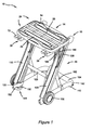
- Figure 1 is a front perspective view of the workbench according to the present invention shown in an expanded position;
- Figure 2 is a side view of the workbench shown in an expanded position;
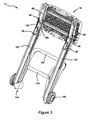
- Figure 3 is a rear perspective view of the workbench shown in a collapsed position;
- Figure 4 is a side view of the workbench shown in a collapsed position;
- Figure 5 is a top view of a top member of the workbench;
- Figure 6 is a bottom view of a top member of the workbench;
- Figure 7 is a bottom perspective view of the top structure and support structure of the workbench;
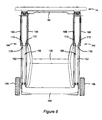
- Figure 8 is a rear view of the workbench in an expanded position;
- Figure 9 is a perspective view of a support member; and
- Figure 10 is a plan view of a leg incorporated in the collapsible frame.
-
- The following description of the preferred embodiment(s) is merely exemplary in nature and is in no way intended to limit the invention, its application, or uses.
- With initial reference to Figures 1-4, a
portable workbench 10 according to the present invention is shown. Workbench 10 generally includes atop structure 14, asupport structure 18 and acollapsible frame 20.Workbench 10 is movable between an expanded position, as shown in Figure 1, and a collapsed position, as shown in Figure 3. - With continued reference to Figures 1-4 and further reference to Figures 5 and 6,
top structure 14 will be described in greater detail.Top structure 14 includes a pair of elongated mutually adjacenttop members 24 including upperwork supporting surfaces 26 lying generally in a common plane.Top members 24 are further defined bystationary member 28 and translatingmember 30.Top members 24 include longitudinally extendingopposed side portions 36 defining clamping surfaces. As will be described in greater detail, translatingmember 30 is adjustable toward and away fromstationary member 28 by way of a screw-type clamping device 38. -
Top members 24 are preferably made of injection molded polypropylene. Eachtop member 24 includes molded thereon a plurality ofbore sections 40 for durability.Bore sections 40 also accept accessory pegs (not shown) which increase the clamping range for larger workpieces. The underside of each top member 24 (Figure 6) includes a plurality ofrib sections 42 formed thereon for increased stability.Rib sections 42 are shown generally as rectangular portions but may also be arranged in other geometric shapes such as hexagonal for example. Opposingclamping detents 46 are formed along each opposedside portion 36. Clampingdetents 46 provide a gripping function to locate a workpiece in a fixed location between theclamping surface 36 or alternatively are arranged to accommodate extending portions of a workpiece. Ahandle 48 is integrally formed on an outer edge of eachtop member 24. A pair ofcounter bores 50 are arranged on eachtop member 24 for accepting fasteners tocouple support structure 18 thereto. - Recessed
portions 54 arranged on the outer corners of eachtop member 26 provide convenient locating areas for small parts such as fasteners and the like. The transition between workingsurfaces 26 and aperipheral edge 56 oftop members 26 is defined by aradial contour 58.Radial contour 58 provides increased stability to thetop structure 14 as a whole and is also accommodating to the touch. - Turning now to Figures 7 and 9,
support structure 18 will be described in greater detail.Support structure 18 includes a pair of generally u-shaped laterally disposedsupport members 60.Stationary member 28 is coupled throughblind bores 50 to supportmembers 60 atmounting bores 64 with conventional fasteners (not shown). Translatingmember 30 is coupled through respectiveblind bores 50 to mountingcollars 66.Mounting collars 66 are threadably journalled around respective adjustingrods 68.Collars 66 are guided along threads formed along adjustingrods 68 upon rotation of the adjustingrods 68. Adjustingrods 68 extend through afront passage 70 incorporated on eachsupport member 60 and terminate athandles 72. Adjustingrods 68 cooperate withcollars 66 to translate rotational movement ofhandles 72 into lateral movement of translatingmember 30 alongsupport members 60. In this way,cutout portion 76 accommodates the linear movement ofcollar 66 therealong.Outer edges 78 ofcutout portion 76 boundcollars 66 and define the maximum travel of translatingmember 30. It will be appreciated that other mechanical arrangements may be employed to translatetop members 24 relative to each other in a clamping arrangement. - A handle or
lever 80 is slidably coupled betweensupport members 60 for releasing thecollapsible frame 20 from an expanded position to a collapsed position. Loopedportions 84 are guided along opposingslots 86 arranged along afront portion 88 ofsupport members 60. Similarly, the terminal ends 90 oflever 80 extend through and are guided alongslots 92 incorporated on acentral portion 94 ofsupport members 60. As will be described in greater detail with respect to Figure 10,latch portion 96 oflever 80 is urged toward engagement withnotches 98 formed onlegs 100 by biasingmembers 114. The cooperation oflatch portions 96 withnotches 98 maintainsworkbench 10 in a stable expanded position. Biasingmembers 114 are coupled on a first end toloop portion 84 ofhandle 80 and a mountingextension 108 ofsupport members 60 on a second end.Support members 60 are preferably made of a rigid material such as roll formed metal. - With reference now to all Figures,
collapsible frame 20 incorporatinglinkage mechanism 110 will be described.Frame 20 includes a pair oflegs 100 pivotally extending betweenrespective support members 18 and asupport base 104.Legs 100 are connected on upper ends torespective support members 18 at support member pivot points 120. Similarlylegs 100 are connected on lower ends to respective base support pivot points 122. In an expanded working position (Figures 1 and 2),legs 100 separatetop structure 14 andsupport base 104 into a parallel, spaced apart relationship.Legs 100 are laterally supported bycross brace 126.Cross brace 126 is shown having a generally u-shaped geometry however alternative arrangements may be employed. Aslot 130 is incorporated on eachleg 100 to guidelinkage mechanism 110 between expanded and collapsed positions.Slots 130 are preferably arranged in a J-shaped orientation wherebylinkage mechanism 110 cooperates with a curvedlower section 132 ofslots 130 in an expanded position and cooperates with a generally linearupper section 134 ofslots 130 in a collapsed position. -
Support base 104 includes ground engagingsupport pads 140 secured onouter corners 142.Ground engaging feet 146 extend at the leg, base intersection.Feet 146 each include an inwardly extendingflange 150 providing added ground gripping capability. Eachflange 150 includesgripping ridges 152 formed along an upper edge. In this way, a user may step on one or bothflange 150 to provide increased workbench stability.Wheels 156 are rotatably coupled tolegs 100 at the leg, base intersection.Wheels 156 are arranged such that they are laterally displaced away from the ground whenworkbench 10 is in an expanded position. Whenworkbench 10 is in a collapsed position and tilted towardwheels 156 at an angle with the ground,wheels 156 engage the ground to facilitate movement therealong. Whenworkbench 10 is in a collapsed position and tilted away fromwheels 156, thewheels 156 are precluded from ground engagement. In this way,workbench 10 may be tilted against a wall in a stable position with feet engaging the ground (Figure 4). -
Linkage mechanism 110 includes a pair oflink members 160 operatively connectingsupport members 60 andlegs 100. In addition,linkage mechanism 110 includes a pair of connectingmembers 162 operatively connectingsupport base 104 andlegs 100. Eachlink member 160 generally includes an inboard andoutboard slide arm 166.Slide arms 166 are coupled on a first end for pivotal movement torespective support members 60 at inboard and outboard pivot points 170.Slide arms 166 are coupled on a second end to respective inboard andoutboard posts 172.Posts 172 extend through and are translatable alongslots 130 formed alonglegs 100.Posts 172 are hingedly interconnected tofirst ends 164 of respective connectingmembers 162 by way oflinks 176. Second ends 168 of connectingmembers 162 are pivotally secured to link pivot joints 178 incorporated at mountingflanges 180 extending fromsupport base 104. - The operation of
linkage mechanism 110 will now be described in the context of moving theworkbench 10 from an expanded position (Figure 1) to a collapsed position (Figure 3). First, a user graspslever 80 extending understationary member 28 and actuateslever 80 in a direction toward the user defining a release direction (arrow A, Figure 7). In a first method of operation, the user may place a first hand on a portion of the peripheral edge of stationarytop member 28 while actuatinglever 80 with the other hand. In a second method of operation, the efficiency oflinkage mechanism 110 allows a user to manipulateworkbench 10 from an expanded position to a collapsed position with one hand. Accordingly, a user would position a thumb aroundperipheral edge 56 ofstationary member 28 and pulllever 80 in the release direction with the remaining fingers of the same hand. - Movement of
lever 80 in the release direction disengages latchportions 96 oflever 80 fromnotches 98 onlegs 100. The user subsequently rotateswork surface 26 upward causingsupport members 60 to rotate aboutlegs 100 at support member pivot points 120 (clockwise as viewed from Figure 2). Rotational movement ofsupport members 60 about pivot points 120 urges linkmembers 166 upward alongslots 130. Translation oflink members 166 alongslots 130 concurrently pulls the first ends 164 of connectingmembers 162 along the same path by way of the post and link arrangement. Translation of first ends 164 of connectingmembers 162 causes the second ends 168 of connectingmembers 162 to pivot about link pivot joints 178. Such movement urgessupport base 104 to rotate towardlegs 100 about base pivot joints 122 (counter-clockwise as viewed from Figure 2). Rotation oftop structure 14 continues untilposts 172 engage terminalupper end 134 ofslots 130. - To return the
workbench 10 to an expanded position from a collapsed position a user rotatestop structure 14 counterclockwise as viewed from Figure 4. Concurrently, linkmembers 166follow slot 130 toward J-section 132.Top structure 14 andsupport base 104 expand to the generally parallel relationship upon rotation about respective support member and base pivot points 120, 122. Eachlatch 96 oflever 80 slides along an outerfront surface 182 ofleg 100 nearnotch 98 until engagingnotch 98. Biasingmembers 114 subsequently urge eachlatch 96 intonotch 98 thereby achieving a locked expanded position. - Those skilled in the art can now appreciate from the foregoing description that the broad teachings of the present invention can be implemented in a variety of forms. For example, the workbench disclosed herein is described having slidable link members cooperating on each leg of the collapsible frame. It is envisioned however that the workbench may alternatively incorporate a single linkage cooperating with one leg while reaching similar results. Therefore, while this invention has been described in connection with particular examples thereof, the true scope of the invention should not be so limited since other modifications will become apparent to the skilled practitioner upon a study of the drawings, the specification and the following claims.
Claims (18)
- A portable workbench comprising:a plastic top structure having a pair of mutually adjacent top members lying generally in a common plane, said top members having an upper working surface and a lower supporting surface, said supporting surface including a plurality of rib sections formed thereon, said top members further including longitudinally extending opposed side portions defining clamping surfaces;a support structure supporting said top structure, said support structure including a clamping device for selectively transversing at least one of said top members toward the other of said top members to provide for clamping of a workpiece therebetween; anda collapsible frame connected to said support structure, said frame movable between an expanded position and a collapsed position, said top members forming a substantially parallel relationship with ground in said expanded position and forming a substantially perpendicular relationship with said ground in said collapsed position.
- The portable workbench of claim 1 wherein said top members further comprise a radiused lip extending around an outer perimeter.
- The portable workbench of claim 1 wherein said top members further include apertures formed therethrough defining handles.
- The portable workbench of claim 1 wherein said top members are comprised of injection molded polypropylene.
- The portable workbench of claim 4 wherein said top members include a plurality of cylindrical passages molded therethrough.
- The portable workbench of claim 4 wherein at least one recessed portion is molded on said working surface of said top members.
- The portable workbench of claim 1 wherein said clamping surfaces include at least a pair of opposing clamping detents formed thereon.
- A workbench comprising:a plastic top structure having a pair of mutually adjacent top members lying generally in a common plane, said top members having an upper working surface and a lower supporting surface, said supporting surface including a plurality of rib sections formed thereon, said top members further including radially extending outboard edges and longitudinally extending opposing inboard edges, said inboard edges defining clamping surfaces, said outboard edges connected to said working surface by a radial contour;a clamping device coupled to said top structure, said clamping device selectively transversing at least one of said top members toward the other of said top members to provide for clamping of a workpiece therebetween; anda collapsible frame connected to said top structure and moveable between an expanded working position and a collapsed storage position, said top members forming a substantially parallel relationship with ground in said expanded position and forming a substantially perpendicular relationship with said ground in said collapsed position.
- The portable workbench of claim 8 wherein said top members are comprised of injection molded polypropylene.
- The portable workbench of claim 8 wherein said top members further include apertures formed therethrough defining handles.
- The portable workbench of claim 8 wherein said top members include a plurality of cylindrical passages molded therethrough.
- The portable workbench of claim 8 wherein at least one recessed portion is molded on said working surface of said top members.
- The portable workbench of claim 8 wherein said clamping surfaces include at least a pair of opposing clamping detents formed thereon.
- A workbench comprising:a plastic top structure having a pair of mutually adjacent top members lying generally in a common plane, said top members having an upper working surface and a lower supporting surface, said supporting surface including a plurality of rib sections formed thereon, said top members further including radially extending outboard edges and longitudinally extending opposing inboard edges, said inboard edges defining clamping surfaces, said outboard edges connected to said working surface by a radial contour, said top members including a plurality of cylindrical passages formed therethrough;a clamping device coupled to said top structure, said clamping device selectively transversing at least one of said top members toward the other of said top members to provide for clamping of a workpiece therebetween; anda collapsible frame connected to said top structure and moveable between an expanded working position and a collapsed storage position, said top members forming a substantially parallel relationship with ground in said expanded position and forming a substantially perpendicular relationship with said ground in said collapsed position.
- The portable workbench of claim 14 wherein said top members are comprised of injection molded polypropylene.
- The portable workbench of claim 14 wherein said top members further include apertures formed therethrough defining handles.
- The portable workbench of claim 14 wherein at least one recessed portion is molded on said working surface of said top members.
- The portable workbench of claim 14 wherein said clamping surfaces include at least a pair of opposing clamping detents formed thereon.
Applications Claiming Priority (2)
| Application Number | Priority Date | Filing Date | Title |
|---|---|---|---|
| US245173 | 2002-09-17 | ||
| US10/245,173 US6848684B2 (en) | 2002-09-17 | 2002-09-17 | Workbench having plastic clamping work surface |
Publications (2)
| Publication Number | Publication Date |
|---|---|
| EP1400321A1 true EP1400321A1 (en) | 2004-03-24 |
| EP1400321B1 EP1400321B1 (en) | 2006-11-22 |
Family
ID=31946404
Family Applications (1)
| Application Number | Title | Priority Date | Filing Date |
|---|---|---|---|
| EP03021003A Expired - Lifetime EP1400321B1 (en) | 2002-09-17 | 2003-09-17 | Workbench having a plastic clamping work surface |
Country Status (5)
| Country | Link |
|---|---|
| US (1) | US6848684B2 (en) |
| EP (1) | EP1400321B1 (en) |
| CN (1) | CN100431801C (en) |
| AT (1) | ATE345905T1 (en) |
| DE (1) | DE60309798T2 (en) |
Cited By (2)
| Publication number | Priority date | Publication date | Assignee | Title |
|---|---|---|---|---|
| US7588255B2 (en) | 2004-11-10 | 2009-09-15 | Zag Industries, Ltd. | Collapsible clamping work table |
| WO2017033147A1 (en) * | 2015-08-25 | 2017-03-02 | Polisport Plásticos, Sa. | Support stand and use |
Families Citing this family (20)
| Publication number | Priority date | Publication date | Assignee | Title |
|---|---|---|---|---|
| WO2005016601A2 (en) * | 2003-08-05 | 2005-02-24 | Black & Decker Inc. | Folding bench with hand truck capabilities |
| DE102005010354B4 (en) * | 2005-03-08 | 2013-03-07 | Wolfcraft Gmbh | Foldable chop saw stand |
| US20070120034A1 (en) * | 2005-11-08 | 2007-05-31 | Sparling David R | Xdeck laptop/book-holder |
| US8096026B2 (en) * | 2006-01-03 | 2012-01-17 | Joby Photo, Inc. | Accessory clips and mounting apparatus using same |
| US20110180682A1 (en) * | 2006-03-23 | 2011-07-28 | Byron Richard Tarnutzer | Deployable support unit for reading material |
| US7828260B2 (en) * | 2006-03-23 | 2010-11-09 | Hauser Stephen G | Deployable support unit for reading material |
| US8567740B2 (en) * | 2006-03-23 | 2013-10-29 | Byron Richard Tarnutzer | Deployable support unit for reading material |
| US8403314B2 (en) * | 2007-09-07 | 2013-03-26 | Robert Bosch Gmbh | Dog hole layout for a workbench system |
| US8042794B2 (en) | 2008-07-02 | 2011-10-25 | Black & Decker Inc. | Workbench with saw horse |
| US20200023872A1 (en) * | 2018-07-23 | 2020-01-23 | Matthew McCrillis | Welding Cart |
| US11027411B2 (en) | 2018-10-24 | 2021-06-08 | Tti (Macao Commercial Offshore) Limited | Saw stand |
| US11890744B2 (en) | 2020-07-31 | 2024-02-06 | Techtronic Cordless Gp | Workbench-hand truck assembly |
| US11883945B2 (en) | 2022-04-12 | 2024-01-30 | Michael H Panosian | Foldable workbench |
| USD1063376S1 (en) | 2022-06-08 | 2025-02-25 | Yeti Coolers, Llc | Container |
| US11912477B2 (en) | 2022-06-08 | 2024-02-27 | Yeti Coolers, Llc | Container with handle and latching system |
| USD1024557S1 (en) | 2022-06-08 | 2024-04-30 | Yeti Coolers, Llc | Container |
| USD1036116S1 (en) | 2022-06-08 | 2024-07-23 | Yeti Coolers, Llc | Container |
| USD1036119S1 (en) | 2022-11-30 | 2024-07-23 | Yeti Coolers, Llc | Container |
| CN117884615A (en) * | 2023-03-01 | 2024-04-16 | 四川东晟源建设工程有限公司 | Auxiliary equipment for casting engineering machinery differential mechanism shell |
| US12502720B2 (en) * | 2023-12-19 | 2025-12-23 | Robert Bosch Gmbh | Table saw with gravity rise stand |
Citations (4)
| Publication number | Priority date | Publication date | Assignee | Title |
|---|---|---|---|---|
| US4555099A (en) * | 1983-06-17 | 1985-11-26 | Hilton (Products) Limited | Workbenches |
| US5595228A (en) * | 1994-08-12 | 1997-01-21 | Black & Decker Inc. | Utility box incorporating an integral clamping vise |
| DE19909830A1 (en) * | 1999-03-05 | 2000-09-07 | Wolfcraft Gmbh | Workbench |
| WO2002060649A2 (en) * | 2000-12-18 | 2002-08-08 | Zag Industries, Ltd. | Portable support assembly for a workpiece |
Family Cites Families (54)
| Publication number | Priority date | Publication date | Assignee | Title |
|---|---|---|---|---|
| US2449492A (en) | 1947-07-24 | 1948-09-14 | Albert T Long | Lectern |
| US3349728A (en) | 1966-11-25 | 1967-10-31 | American Seating Co | Folding table |
| US4216949A (en) | 1968-03-04 | 1980-08-12 | Inventec International Limited | Workbenches |
| GB1267033A (en) | 1968-03-04 | 1972-03-15 | ||
| US3841619A (en) | 1968-03-04 | 1974-10-15 | Inventec Int Ltd | Workbenches |
| US4076229A (en) | 1968-03-04 | 1978-02-28 | Inventec International Limited | Workbenches |
| US4140309A (en) | 1968-03-04 | 1979-02-20 | Inventec International Limited | Workbenches |
| US3676279A (en) | 1970-06-16 | 1972-07-11 | All Steel Equipment Inc | Sandwich top construction for office furniture |
| US4159821A (en) | 1971-08-02 | 1979-07-03 | Inventec International Limited | Collapsible dual-height workbench |
| IT961759B (en) | 1971-08-02 | 1973-12-10 | Hickman R | IMPROVEMENT IN THE CLAMPING STRUCTURES FOR WORKPIECES RATION |
| CA1061396A (en) | 1974-09-12 | 1979-08-28 | Norman H. Carson | Workbench and foldable leg assembly therefor |
| IT1054874B (en) * | 1976-02-19 | 1981-11-30 | Star Utensili Elett | FOLDABLE WORKBENCH |
| US4061323A (en) | 1976-03-09 | 1977-12-06 | The Black And Decker Manufacturing Company | Workpiece supporting and clamping apparatus |
| US4127260A (en) | 1976-04-02 | 1978-11-28 | Inventec International Limited | Workbench with quick setting vise structure |
| IT1120425B (en) | 1976-05-05 | 1986-03-26 | Inventec Patents Ltd | IMPROVEMENTS IN WORKBENCHES |
| US4015330A (en) * | 1976-05-05 | 1977-04-05 | Popeil Brothers, Inc. | Cutting board case and knife set |
| USD250079S (en) | 1976-07-22 | 1978-10-31 | Hickman Ronald P | Workbench |
| US4073484A (en) | 1976-10-04 | 1978-02-14 | The Black And Decker Manufacturing Company | Portable workbench assembly |
| US4061305A (en) | 1976-10-04 | 1977-12-06 | The Black And Decker Manufacturing Company | Foldable, portable support stand |
| USD253212S (en) | 1977-11-03 | 1979-10-23 | Black & Decker Inc. | Workbench |
| GB1604658A (en) | 1977-11-28 | 1981-12-16 | Inventee Licensing Bv | Stools |
| CA1127675A (en) | 1978-01-12 | 1982-07-13 | Charles W. Pettican | Workbench |
| USD256533S (en) | 1978-02-22 | 1980-08-26 | Black & Decker Inc. | Portable workbench |
| US4154435A (en) | 1978-02-22 | 1979-05-15 | The Black And Decker Manufacturing Company | Portable workbench |
| USD256641S (en) | 1978-03-13 | 1980-09-02 | Black & Decker Inc. | Portable workbench |
| GB1604719A (en) | 1978-05-25 | 1981-12-16 | Inventec Licensing Bv | Portable work units |
| GB2042040B (en) | 1978-05-30 | 1982-07-14 | Inventec Patents Ltd | Foldable step-stool |
| US4310150A (en) | 1978-10-05 | 1982-01-12 | Black & Decker Inc. | Workbench |
| US4294441A (en) * | 1979-05-15 | 1981-10-13 | Banion Michael L O | Apparatus for supporting a work piece |
| US4248411A (en) | 1979-05-15 | 1981-02-03 | Black And Decker, Inc. | Apparatus for supporting a work piece |
| US4243212A (en) * | 1979-05-29 | 1981-01-06 | Black And Decker Manufacturing Company | Means for restraining a swivel vise |
| US4625951A (en) | 1985-02-08 | 1986-12-02 | Yang Tai Her | Workbench and clamp structure |
| AU92671S (en) | 1985-02-22 | 1986-07-17 | Micro Shuttle Australia Pty Ltd | A trolley |
| US4726556A (en) | 1986-01-27 | 1988-02-23 | Weir Stanley M | Holder table |
| US4951576A (en) | 1988-10-17 | 1990-08-28 | Bryan Equipment Company, Inc. | Plastic support surface structure |
| DE3910826C1 (en) | 1989-04-04 | 1990-11-08 | Werkzeug Gmbh, 5441 Weibern, De | |
| USD333390S (en) | 1990-01-29 | 1993-02-23 | Mccauley Stephanie S | Folding table |
| USD335786S (en) | 1991-09-06 | 1993-05-25 | Grolen Incorporated | Computer workstation |
| US5351730A (en) | 1993-07-23 | 1994-10-04 | Rubbermaid Incorporated | Multipurpose portable workbench |
| US5417168A (en) | 1993-10-15 | 1995-05-23 | Ino-Products Inc. | Folding table |
| US5443020A (en) | 1993-12-13 | 1995-08-22 | Alltrista Corporation | Plastic table structure |
| US5603491A (en) | 1995-06-16 | 1997-02-18 | Murrell; Anthony S. | Portable workstand module |
| US5694865A (en) | 1995-10-24 | 1997-12-09 | Virco Mfg. Corporation | Lightweight plastic furniture |
| US5732637A (en) | 1995-10-24 | 1998-03-31 | Virco Mfg. Corporation | Lightweight plastic furniture |
| USD409016S (en) | 1997-04-25 | 1999-05-04 | Rubbermaid Incorporated | Mobile workbench |
| US5931488A (en) | 1997-05-06 | 1999-08-03 | Bretford Manufacturing, Inc. | Wheeled folding table |
| TW388325U (en) | 1998-03-18 | 2000-04-21 | Novelty 21St Corp | Electric circular saw workbench having material cutting rail with aligning apparatus |
| US6019050A (en) | 1998-09-15 | 2000-02-01 | Ranta; Jouko Y. | Portable and adjustable table with improved leg assembly |
| US6318713B1 (en) * | 1999-08-12 | 2001-11-20 | Zag Industries Ltd. | Portable workbench |
| US6286824B1 (en) * | 1999-11-01 | 2001-09-11 | Keter Plastic Ltd. | Collapsible worktable |
| USD448200S1 (en) | 2000-02-16 | 2001-09-25 | Keter Plastic Ltd. | Work bench |
| USD435367S (en) | 2000-03-28 | 2000-12-26 | Ren-Ju Tzeng | Computer desk |
| USD436268S1 (en) | 2000-04-10 | 2001-01-16 | Wen-Shan Ko | Computer desk |
| USD449470S1 (en) | 2001-02-28 | 2001-10-23 | Palliser Furniture, Ltd. | Desk |
-
2002
- 2002-09-17 US US10/245,173 patent/US6848684B2/en not_active Expired - Fee Related
-
2003
- 2003-09-17 CN CNB031272746A patent/CN100431801C/en not_active Expired - Fee Related
- 2003-09-17 DE DE60309798T patent/DE60309798T2/en not_active Expired - Lifetime
- 2003-09-17 AT AT03021003T patent/ATE345905T1/en not_active IP Right Cessation
- 2003-09-17 EP EP03021003A patent/EP1400321B1/en not_active Expired - Lifetime
Patent Citations (4)
| Publication number | Priority date | Publication date | Assignee | Title |
|---|---|---|---|---|
| US4555099A (en) * | 1983-06-17 | 1985-11-26 | Hilton (Products) Limited | Workbenches |
| US5595228A (en) * | 1994-08-12 | 1997-01-21 | Black & Decker Inc. | Utility box incorporating an integral clamping vise |
| DE19909830A1 (en) * | 1999-03-05 | 2000-09-07 | Wolfcraft Gmbh | Workbench |
| WO2002060649A2 (en) * | 2000-12-18 | 2002-08-08 | Zag Industries, Ltd. | Portable support assembly for a workpiece |
Cited By (2)
| Publication number | Priority date | Publication date | Assignee | Title |
|---|---|---|---|---|
| US7588255B2 (en) | 2004-11-10 | 2009-09-15 | Zag Industries, Ltd. | Collapsible clamping work table |
| WO2017033147A1 (en) * | 2015-08-25 | 2017-03-02 | Polisport Plásticos, Sa. | Support stand and use |
Also Published As
| Publication number | Publication date |
|---|---|
| CN100431801C (en) | 2008-11-12 |
| CN1494997A (en) | 2004-05-12 |
| DE60309798D1 (en) | 2007-01-04 |
| US20040051224A1 (en) | 2004-03-18 |
| EP1400321B1 (en) | 2006-11-22 |
| ATE345905T1 (en) | 2006-12-15 |
| US6848684B2 (en) | 2005-02-01 |
| DE60309798T2 (en) | 2007-10-11 |
Similar Documents
| Publication | Publication Date | Title |
|---|---|---|
| US6848684B2 (en) | Workbench having plastic clamping work surface | |
| EP1557243B1 (en) | Portable workbench having collapsible support structure | |
| US8740207B2 (en) | Folding bench | |
| US4415149A (en) | Portable workbench | |
| EP1527848B1 (en) | Collapsible stand for a bench-top power tool | |
| US6360797B1 (en) | Power tool and portable support assembly | |
| CN215752437U (en) | Trolley assembly of workbench | |
| US4555099A (en) | Workbenches | |
| US10093017B2 (en) | Sawhorse | |
| US5778953A (en) | Method and apparatus for carrying and supporting a portable bench top saw | |
| US11548137B2 (en) | Saw stand | |
| US20090000442A1 (en) | Rotary Trimmer | |
| US5064156A (en) | Adjustable height work support | |
| US4483524A (en) | Unitary latching and release means for portable foldable workbench | |
| US4442779A (en) | Unitary latching and release means for portable foldable workbench | |
| US7430968B2 (en) | Folding work platform | |
| EP0098101A2 (en) | Vice and workbenches | |
| US6581656B1 (en) | Portable power tool extension table | |
| US7320383B1 (en) | Heavy duty fold out saw horse | |
| GB2329355A (en) | Moulded plastic trestle workbench | |
| GB2187411A (en) | Workbench | |
| GB2353495A (en) | Work support |
Legal Events
| Date | Code | Title | Description |
|---|---|---|---|
| PUAI | Public reference made under article 153(3) epc to a published international application that has entered the european phase |
Free format text: ORIGINAL CODE: 0009012 |
|
| AK | Designated contracting states |
Kind code of ref document: A1 Designated state(s): AT BE BG CH CY CZ DE DK EE ES FI FR GB GR HU IE IT LI LU MC NL PT RO SE SI SK TR |
|
| AX | Request for extension of the european patent |
Extension state: AL LT LV MK |
|
| 17P | Request for examination filed |
Effective date: 20040413 |
|
| AKX | Designation fees paid |
Designated state(s): AT BE BG CH CY CZ DE DK EE ES FI FR GB GR HU IE IT LI LU MC NL PT RO SE SI SK TR |
|
| 17Q | First examination report despatched |
Effective date: 20041215 |
|
| GRAP | Despatch of communication of intention to grant a patent |
Free format text: ORIGINAL CODE: EPIDOSNIGR1 |
|
| GRAS | Grant fee paid |
Free format text: ORIGINAL CODE: EPIDOSNIGR3 |
|
| GRAA | (expected) grant |
Free format text: ORIGINAL CODE: 0009210 |
|
| AK | Designated contracting states |
Kind code of ref document: B1 Designated state(s): AT BE BG CH CY CZ DE DK EE ES FI FR GB GR HU IE IT LI LU MC NL PT RO SE SI SK TR |
|
| PG25 | Lapsed in a contracting state [announced via postgrant information from national office to epo] |
Ref country code: SI Free format text: LAPSE BECAUSE OF FAILURE TO SUBMIT A TRANSLATION OF THE DESCRIPTION OR TO PAY THE FEE WITHIN THE PRESCRIBED TIME-LIMIT Effective date: 20061122 Ref country code: CZ Free format text: LAPSE BECAUSE OF FAILURE TO SUBMIT A TRANSLATION OF THE DESCRIPTION OR TO PAY THE FEE WITHIN THE PRESCRIBED TIME-LIMIT Effective date: 20061122 Ref country code: FI Free format text: LAPSE BECAUSE OF FAILURE TO SUBMIT A TRANSLATION OF THE DESCRIPTION OR TO PAY THE FEE WITHIN THE PRESCRIBED TIME-LIMIT Effective date: 20061122 Ref country code: RO Free format text: LAPSE BECAUSE OF FAILURE TO SUBMIT A TRANSLATION OF THE DESCRIPTION OR TO PAY THE FEE WITHIN THE PRESCRIBED TIME-LIMIT Effective date: 20061122 Ref country code: SK Free format text: LAPSE BECAUSE OF FAILURE TO SUBMIT A TRANSLATION OF THE DESCRIPTION OR TO PAY THE FEE WITHIN THE PRESCRIBED TIME-LIMIT Effective date: 20061122 |
|
| REG | Reference to a national code |
Ref country code: GB Ref legal event code: FG4D |
|
| REG | Reference to a national code |
Ref country code: CH Ref legal event code: EP |
|
| REG | Reference to a national code |
Ref country code: IE Ref legal event code: FG4D |
|
| REF | Corresponds to: |
Ref document number: 60309798 Country of ref document: DE Date of ref document: 20070104 Kind code of ref document: P |
|
| PG25 | Lapsed in a contracting state [announced via postgrant information from national office to epo] |
Ref country code: DK Free format text: LAPSE BECAUSE OF FAILURE TO SUBMIT A TRANSLATION OF THE DESCRIPTION OR TO PAY THE FEE WITHIN THE PRESCRIBED TIME-LIMIT Effective date: 20070222 Ref country code: BG Free format text: LAPSE BECAUSE OF FAILURE TO SUBMIT A TRANSLATION OF THE DESCRIPTION OR TO PAY THE FEE WITHIN THE PRESCRIBED TIME-LIMIT Effective date: 20070222 |
|
| PG25 | Lapsed in a contracting state [announced via postgrant information from national office to epo] |
Ref country code: ES Free format text: LAPSE BECAUSE OF FAILURE TO SUBMIT A TRANSLATION OF THE DESCRIPTION OR TO PAY THE FEE WITHIN THE PRESCRIBED TIME-LIMIT Effective date: 20070305 |
|
| REG | Reference to a national code |
Ref country code: SE Ref legal event code: TRGR |
|
| REG | Reference to a national code |
Ref country code: CH Ref legal event code: NV Representative=s name: E. BLUM & CO. AG PATENT- UND MARKENANWAELTE VSP |
|
| PG25 | Lapsed in a contracting state [announced via postgrant information from national office to epo] |
Ref country code: PT Free format text: LAPSE BECAUSE OF FAILURE TO SUBMIT A TRANSLATION OF THE DESCRIPTION OR TO PAY THE FEE WITHIN THE PRESCRIBED TIME-LIMIT Effective date: 20070423 |
|
| ET | Fr: translation filed | ||
| RIN2 | Information on inventor provided after grant (corrected) |
Inventor name: WATTERS, ROBERT D. Inventor name: READ, CLIFFORD D. Inventor name: SIROIS, MIKE G. Inventor name: MASON, JOHN BRYAN Inventor name: FORTIN, MARC |
|
| PLBE | No opposition filed within time limit |
Free format text: ORIGINAL CODE: 0009261 |
|
| STAA | Information on the status of an ep patent application or granted ep patent |
Free format text: STATUS: NO OPPOSITION FILED WITHIN TIME LIMIT |
|
| 26N | No opposition filed |
Effective date: 20070823 |
|
| PG25 | Lapsed in a contracting state [announced via postgrant information from national office to epo] |
Ref country code: MC Free format text: LAPSE BECAUSE OF NON-PAYMENT OF DUE FEES Effective date: 20070930 Ref country code: GR Free format text: LAPSE BECAUSE OF FAILURE TO SUBMIT A TRANSLATION OF THE DESCRIPTION OR TO PAY THE FEE WITHIN THE PRESCRIBED TIME-LIMIT Effective date: 20070223 |
|
| PG25 | Lapsed in a contracting state [announced via postgrant information from national office to epo] |
Ref country code: EE Free format text: LAPSE BECAUSE OF FAILURE TO SUBMIT A TRANSLATION OF THE DESCRIPTION OR TO PAY THE FEE WITHIN THE PRESCRIBED TIME-LIMIT Effective date: 20061122 |
|
| PG25 | Lapsed in a contracting state [announced via postgrant information from national office to epo] |
Ref country code: CY Free format text: LAPSE BECAUSE OF FAILURE TO SUBMIT A TRANSLATION OF THE DESCRIPTION OR TO PAY THE FEE WITHIN THE PRESCRIBED TIME-LIMIT Effective date: 20061122 Ref country code: LU Free format text: LAPSE BECAUSE OF NON-PAYMENT OF DUE FEES Effective date: 20070917 |
|
| PG25 | Lapsed in a contracting state [announced via postgrant information from national office to epo] |
Ref country code: HU Free format text: LAPSE BECAUSE OF FAILURE TO SUBMIT A TRANSLATION OF THE DESCRIPTION OR TO PAY THE FEE WITHIN THE PRESCRIBED TIME-LIMIT Effective date: 20070523 Ref country code: TR Free format text: LAPSE BECAUSE OF FAILURE TO SUBMIT A TRANSLATION OF THE DESCRIPTION OR TO PAY THE FEE WITHIN THE PRESCRIBED TIME-LIMIT Effective date: 20061122 |
|
| PGFP | Annual fee paid to national office [announced via postgrant information from national office to epo] |
Ref country code: IE Payment date: 20090925 Year of fee payment: 7 |
|
| PGFP | Annual fee paid to national office [announced via postgrant information from national office to epo] |
Ref country code: AT Payment date: 20090902 Year of fee payment: 7 Ref country code: CH Payment date: 20090925 Year of fee payment: 7 |
|
| PGFP | Annual fee paid to national office [announced via postgrant information from national office to epo] |
Ref country code: IT Payment date: 20090925 Year of fee payment: 7 |
|
| PGFP | Annual fee paid to national office [announced via postgrant information from national office to epo] |
Ref country code: BE Payment date: 20091026 Year of fee payment: 7 |
|
| BERE | Be: lapsed |
Owner name: BLACK & DECKER INC. Effective date: 20100930 |
|
| REG | Reference to a national code |
Ref country code: CH Ref legal event code: PL |
|
| PG25 | Lapsed in a contracting state [announced via postgrant information from national office to epo] |
Ref country code: IT Free format text: LAPSE BECAUSE OF NON-PAYMENT OF DUE FEES Effective date: 20100917 |
|
| PG25 | Lapsed in a contracting state [announced via postgrant information from national office to epo] |
Ref country code: LI Free format text: LAPSE BECAUSE OF NON-PAYMENT OF DUE FEES Effective date: 20100930 Ref country code: BE Free format text: LAPSE BECAUSE OF NON-PAYMENT OF DUE FEES Effective date: 20100930 Ref country code: CH Free format text: LAPSE BECAUSE OF NON-PAYMENT OF DUE FEES Effective date: 20100930 Ref country code: IE Free format text: LAPSE BECAUSE OF NON-PAYMENT OF DUE FEES Effective date: 20100917 |
|
| PG25 | Lapsed in a contracting state [announced via postgrant information from national office to epo] |
Ref country code: AT Free format text: LAPSE BECAUSE OF NON-PAYMENT OF DUE FEES Effective date: 20100917 |
|
| REG | Reference to a national code |
Ref country code: FR Ref legal event code: PLFP Year of fee payment: 14 |
|
| PGFP | Annual fee paid to national office [announced via postgrant information from national office to epo] |
Ref country code: DE Payment date: 20160913 Year of fee payment: 14 Ref country code: NL Payment date: 20160913 Year of fee payment: 14 Ref country code: GB Payment date: 20160914 Year of fee payment: 14 |
|
| PGFP | Annual fee paid to national office [announced via postgrant information from national office to epo] |
Ref country code: SE Payment date: 20160914 Year of fee payment: 14 Ref country code: FR Payment date: 20160816 Year of fee payment: 14 |
|
| REG | Reference to a national code |
Ref country code: DE Ref legal event code: R119 Ref document number: 60309798 Country of ref document: DE |
|
| REG | Reference to a national code |
Ref country code: SE Ref legal event code: EUG |
|
| REG | Reference to a national code |
Ref country code: NL Ref legal event code: MM Effective date: 20171001 |
|
| GBPC | Gb: european patent ceased through non-payment of renewal fee |
Effective date: 20170917 |
|
| PG25 | Lapsed in a contracting state [announced via postgrant information from national office to epo] |
Ref country code: NL Free format text: LAPSE BECAUSE OF NON-PAYMENT OF DUE FEES Effective date: 20171001 |
|
| REG | Reference to a national code |
Ref country code: FR Ref legal event code: ST Effective date: 20180531 |
|
| PG25 | Lapsed in a contracting state [announced via postgrant information from national office to epo] |
Ref country code: DE Free format text: LAPSE BECAUSE OF NON-PAYMENT OF DUE FEES Effective date: 20180404 Ref country code: GB Free format text: LAPSE BECAUSE OF NON-PAYMENT OF DUE FEES Effective date: 20170917 |
|
| PG25 | Lapsed in a contracting state [announced via postgrant information from national office to epo] |
Ref country code: FR Free format text: LAPSE BECAUSE OF NON-PAYMENT OF DUE FEES Effective date: 20171002 |
|
| PG25 | Lapsed in a contracting state [announced via postgrant information from national office to epo] |
Ref country code: SE Free format text: LAPSE BECAUSE OF NON-PAYMENT OF DUE FEES Effective date: 20170918 |