EP1400306A2 - Method and apparatus for aligning a machine tool - Google Patents
Method and apparatus for aligning a machine tool Download PDFInfo
- Publication number
- EP1400306A2 EP1400306A2 EP03255940A EP03255940A EP1400306A2 EP 1400306 A2 EP1400306 A2 EP 1400306A2 EP 03255940 A EP03255940 A EP 03255940A EP 03255940 A EP03255940 A EP 03255940A EP 1400306 A2 EP1400306 A2 EP 1400306A2
- Authority
- EP
- European Patent Office
- Prior art keywords
- slide assembly
- base
- workpiece holder
- machine tool
- tool
- Prior art date
- Legal status (The legal status is an assumption and is not a legal conclusion. Google has not performed a legal analysis and makes no representation as to the accuracy of the status listed.)
- Withdrawn
Links
- 238000000034 method Methods 0.000 title claims abstract description 17
- 238000009760 electrical discharge machining Methods 0.000 claims description 18
- 230000000295 complement effect Effects 0.000 claims description 11
- 238000003754 machining Methods 0.000 description 7
- 239000000919 ceramic Substances 0.000 description 4
- 229910010293 ceramic material Inorganic materials 0.000 description 2
- 238000010420 art technique Methods 0.000 description 1
- 230000000712 assembly Effects 0.000 description 1
- 238000000429 assembly Methods 0.000 description 1
- 239000012212 insulator Substances 0.000 description 1
- 230000000452 restraining effect Effects 0.000 description 1
Images




Classifications
-
- B—PERFORMING OPERATIONS; TRANSPORTING
- B23—MACHINE TOOLS; METAL-WORKING NOT OTHERWISE PROVIDED FOR
- B23Q—DETAILS, COMPONENTS, OR ACCESSORIES FOR MACHINE TOOLS, e.g. ARRANGEMENTS FOR COPYING OR CONTROLLING; MACHINE TOOLS IN GENERAL CHARACTERISED BY THE CONSTRUCTION OF PARTICULAR DETAILS OR COMPONENTS; COMBINATIONS OR ASSOCIATIONS OF METAL-WORKING MACHINES, NOT DIRECTED TO A PARTICULAR RESULT
- B23Q3/00—Devices holding, supporting, or positioning work or tools, of a kind normally removable from the machine
- B23Q3/18—Devices holding, supporting, or positioning work or tools, of a kind normally removable from the machine for positioning only
- B23Q3/186—Aligning devices
-
- B—PERFORMING OPERATIONS; TRANSPORTING
- B23—MACHINE TOOLS; METAL-WORKING NOT OTHERWISE PROVIDED FOR
- B23H—WORKING OF METAL BY THE ACTION OF A HIGH CONCENTRATION OF ELECTRIC CURRENT ON A WORKPIECE USING AN ELECTRODE WHICH TAKES THE PLACE OF A TOOL; SUCH WORKING COMBINED WITH OTHER FORMS OF WORKING OF METAL
- B23H1/00—Electrical discharge machining, i.e. removing metal with a series of rapidly recurring electrical discharges between an electrode and a workpiece in the presence of a fluid dielectric
- B23H1/04—Electrodes specially adapted therefor or their manufacture
-
- B—PERFORMING OPERATIONS; TRANSPORTING
- B23—MACHINE TOOLS; METAL-WORKING NOT OTHERWISE PROVIDED FOR
- B23H—WORKING OF METAL BY THE ACTION OF A HIGH CONCENTRATION OF ELECTRIC CURRENT ON A WORKPIECE USING AN ELECTRODE WHICH TAKES THE PLACE OF A TOOL; SUCH WORKING COMBINED WITH OTHER FORMS OF WORKING OF METAL
- B23H7/00—Processes or apparatus applicable to both electrical discharge machining and electrochemical machining
- B23H7/26—Apparatus for moving or positioning electrode relatively to workpiece; Mounting of electrode
-
- Y—GENERAL TAGGING OF NEW TECHNOLOGICAL DEVELOPMENTS; GENERAL TAGGING OF CROSS-SECTIONAL TECHNOLOGIES SPANNING OVER SEVERAL SECTIONS OF THE IPC; TECHNICAL SUBJECTS COVERED BY FORMER USPC CROSS-REFERENCE ART COLLECTIONS [XRACs] AND DIGESTS
- Y10—TECHNICAL SUBJECTS COVERED BY FORMER USPC
- Y10T—TECHNICAL SUBJECTS COVERED BY FORMER US CLASSIFICATION
- Y10T408/00—Cutting by use of rotating axially moving tool
- Y10T408/55—Cutting by use of rotating axially moving tool with work-engaging structure other than Tool or tool-support
- Y10T408/561—Having tool-opposing, work-engaging surface
- Y10T408/5617—Laterally adjustable surface
Definitions
- This invention relates generally to machine tools and more particularly to alignment of a machine tool which moves a tool along an axis to engage a workpiece.
- Many machine tools operate by moving a tool along an axis to engage a workpiece, for example drill presses, vertical mills, broaches, etc.
- EDM electrical discharge machining
- a linear slide which carries a clamp holding an electrode.
- the linear slide is mounted to a base by an insulator, such as a ceramic tube.
- An interchangeable part holder is attached to the base.
- the part holder must be accurately positioned laterally with respect to the linear slide. This typically requires that the base be custom machined, which is expensive and time consuming.
- a machine tool comprising a base, a slide assembly attached to the base for supporting a tool and translating the tool along an axis, and a workpiece holder attached to the base. At least one of the slide assembly and the workpiece holder are movable laterally with respect to the axis. Means are provided for aligning the slide assembly and the workpiece holder in a desired lateral relationship. A method of aligning a machine tool is also provided.
- Figure 1 illustrates a station of a prior art electrical discharge machining ("EDM") fixture 10, which is representative of a machine tool which carries a tool that moves along an axis to engage a workpiece.
- EDM electrical discharge machining
- the Z-direction is parallel to the movement of the tool along the major axis of the slide
- the Y-direction represents “in” and “out” motion when viewed from the front of the EDM fixture 10
- the X-direction represents "left” and “right” motion when viewed from the front of the EDM fixture 10.
- the term “vertical” is used herein to refer to movement parallel to the Z-axis, while the term “lateral” refers to movement parallel to the X-Y plane.
- the main components of the EDM fixture 10 are a base 12, a locating plate 14, one or more ceramic insulating tubes 15, a slide assembly mounting plate 16, a slide assembly 18 including a stationary member 20 and a slide 22, an electrode holder 24, and a part holder 26.
- the slide assembly 18 has very precise motion (that is, it exhibits very little lateral motion) once properly positioned. However, the slide assembly 18 with its attached electrode holder 24 must be accurately positioned relative to the part holder 26 during the initial setup to ensure correct positioning.
- the prior art technique used to align the electrode holder 24 is to first partially assemble the fixture 10. In doing so, the slide assembly 18 is attached to the insulating tubes 15 by the slide assembly mounting plate 16 in a nominal lateral position.
- nominal position is used herein to mean a preselected position which may not account for variance in the actual dimensions of an individual component.
- the location of the slide 22 is then measured, for example with a coordinate measuring machine.
- a keyway 13 is then custom machined into the locating plate 14 to eliminate any positional error in the slide assembly 18.
- the locating plate 14 precisely positions the part holder 26 relative to the ceramic insulating tubes 15. If multiple operating stations are being used, this process is repeated for each station. While this alignment process results in an accurate setup, it is costly and time consuming because of the need to measure and machine a locating plate 14 for each individual station.
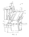
- FIG. 2 An exemplary embodiment of a machine tool 30 constructed according to the present invention is illustrated in Figure 2.
- the main components of the machine tool 30 are a base 32, one or more vertically extending supports 34, a slide assembly 36, a tool holder 38, and a workpiece holder 40.
- the machine tool 30 is depicted as an electrical discharge machining ("EDM") apparatus.
- EDM electrical discharge machining
- the alignment system of the present invention is equally applicable to other types of machine tools which carry a tool that moves along an axis to contact a workpiece, for example a drill press, vertical mill, broach, or the like.
- the slide assembly 36 includes a stationary member 42 and a slide 44.
- the slide 44 is tightly restrained to avoid lateral movement, while moving freely in the Z direction relative to the stationary member 42.
- Typical commercially available units limit lateral motion of the slide 44 to about 0.013 mm (0.0005 in.)
- Suitable slide assemblies of a known type (often called a linear slide or ball slide) are available from Zero Gage Company, Madison, Michigan 48170.
- the slide assembly 36 is not limited to this particular type of slide assembly. Any known type of structure which allows free movement of a tool along an axis and restrains movement lateral to the axis may be used.
- the illustrated slide assembly 36 includes an arch 46 which is contacted by a hydraulic press, micrometer feed assembly, linear motor, or other known means for traversing the slide 44 in the Z direction in a controlled manner during a machining operation.
- a spring 48 returns the slide 44 to its starting position at the end of a machining operation.
- the vertically extending supports 34 are attached to the base 32 and the slide assembly 36 and serve to position the slide assembly 36 at a desired distance from the base 32.
- the vertically extending supports 34 are ceramic tubes which electrically insulate the slide assembly 36 from the base 32, as required in an EDM application.
- the machine tool 30 is assembled by mounting the slide assembly 36 and the vertical supports 34 to the base 32 in a manner which allows lateral movement of the slide assembly 36 relative to the base 32.
- this is done by way of clamp bolts 50 which pass through clearance holes 52 in the base 32 and up through the vertically extending supports 34, and thread into the stationary member 42.
- Insulating washers 54 are provided under the heads 56 of the clamp bolts 50 to ensure that the slide assembly 36 remains insulated from the base 32.
- the clamp bolts 50 are tightened the slide assembly 36 is clamped into a fixed position in the lateral direction.
- the tool holder 38 may be any structure capable of holding a tool for engaging a workpiece.
- the tool holder 38 is an EDM electrode clamp assembly.
- the tool holder 38 is attached to the slide 44 and moves with the slide 44.
- the tool holder 38 shown includes a central frame 60 having an electrode clamp 62 attached to each side thereof. For illustrative clarity, one of the electrode clamps 62 is not shown in Figure 3.
- Each electrode clamp 62 receives a bar-shaped EDM electrode 64.
- the tool holder 38 includes a first alignment feature 66.
- the first alignment feature 66 comprises a slot 68 which is formed through the lower edge of the frame 60.
- the workpiece holder 40 has a first portion 70 for locating and restraining a workpiece in a fixed position. Any known type of tooling for holding a workpiece stationary during a machining process may be used, for example a "nest" structure, a spring-clamp structure, a clamp with movable jaws, or other similar device.
- the workpiece holder 40 also has a second portion 72, such as the illustrated flange, which is used to mount the workpiece holder 40 to the base 32.
- the workpiece holder 40 incorporates a second alignment feature 74 having a shape and dimensions complementary to those of the first alignment feature 66.
- the second alignment feature 74 is a vertically extending tab 76 having a square cross-section of approximately the same dimensions as the closed-in slot 68 of the tool holder 38.
- the workpiece holder 40 is attached to the base 32 in a nominal position in the X and Y directions.
- the workpiece holder 40 is restrained in this position by locating means such as dowel pins (not shown) which pass through holes in the base 32 and complementary holes in the workpiece holder 40.
- the slide 44 is then lowered, and the slide assembly 36 moved laterally, until the first alignment feature 66 of the slide assembly 36 is in engagement with the second alignment feature 74 of the workpiece holder 40.
- the slide assembly 36 is then clamped in the aligned position so that it can not move laterally, for example by tightening the clamp bolts 50.
- the electrode clamp 62 and the workpiece holder 40 are thus assured of being aligned in a desired lateral relationship.
- a machining operation may then be carried out by placing a workpiece (not shown) in the workpiece holder 40, advancing the slide 44 so the electrode 64 engages the workpiece, retracting the slide 44, and removing the workpiece.
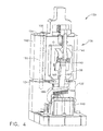
- a machine tool 130 has main components that are similar to those of the machine tool 30 shown in Figure 2, including a base 132, one or more vertically extending supports 134, a slide assembly 136 including a stationary member 142 and a slide 144, a tool holder 138, and a workpiece holder 140.
- the machine tool 130 is assembled by mounting the slide assembly 136 and the vertical supports 134 to the base 132 in a manner which allows lateral movement of the slide assembly 136 relative to the base 132. In the illustrated example this is done by way of clamp bolts 150 which pass through clearance holes (not shown) in the stationary member 142 and down through the vertically extending supports 134, and thread into the base 132. Insulating washers 154, for example of a ceramic material, are provided under the heads 156 of the clamp bolts 150 to ensure that the slide assembly 136 remains electrically insulated from the base 132.
- the illustrated tool holder 138 is this example is an electrode clamp which includes a body 160 having a pair of electrode locator pins 162, such as dowel pins, protruding therefrom.
- the electrode locator pins 160 are received in holes of the electrode 164 to locate the electrode in the Z and X directions.
- a clamp jaw 165 presses against the electrode 164 to hold it against the body 160 and restrains it in the Y-direction.
- the electrode locator pins 160 also cooperate with the body 160 of the tool holder 138 to define first alignment feature 166.
- a separate alignment device 180 (see Figure 5) is provided for the purpose of aligning the slide assembly 136 to the base 132.
- the alignment device 180 has a generally elongated body 182, as shown in more detail in Figures 6 and 7.
- the body 182 has a lower end 184 and an upper end 186.
- the lower end 184 includes means for locating the alignment device 180 in a selected lateral position with respect to the base 132 of the machine tool 130.
- the upper end 186 includes a second alignment feature 174 which is complementary to the first alignment feature 166 of the tool holder 138.
- the second alignment feature 174 comprises first and second plates 188 and 190 which are attached to the body 182 of the alignment device 180.
- the distance t between the plates is selected to be substantially equal to the thickness of the body 160 of the tool holder 138.
- the first plate 188 includes a pair of tabs 192 extending vertically upward from an upper edge thereof.
- the alignment device 180 is secured to the base 132 in a nominal position.
- dowel pins (not shown) could be placed in holes in the base 132 and corresponding holes in the alignment device.
- the slide 144 is then lowered, and the slide assembly 136 moved laterally, until the first alignment feature 166 is in engagement with the second alignment feature 174.
- the body 160 of the tool holder 138 is restrained in the Y direction between the first and second plates 188 and 190, while one of the electrode locator pins 162 is received between the tabs 192 of the alignment device 180 to restrain the tool holder body 160 in the X direction.
- the slide assembly 136 is then secured to the vertical supports 134, for example by tightening the clamp bolts 150.
- the alignment device 180 is then removed and the workpiece holder 140 installed (see Figure 4).
- the workpicece holder 140 is designed so that the worpiece will be held in the proper position when the workpiece holder 140 is attached to the base 132 at the same location where the alignement device 180 was attached during the alignment procedure. Alignment between the tool holder 138 and the workpiece holder 140 is thus assured.
- a machining operation may then be carried out as described above.
- the present invention has been described in terms of aligning a linear slide with a workpiece holder by lateral movement of the linear slide, it is also possible to reverse the process. That is, the linear slide with its first alignment feature could be mounted in a nominal position relative to the vertical supports of the machine tool, and means provided to allow lateral motion of the workpiece holder. It is also possible to allow lateral motion of both the linear slide and the workpiece holder. Furthermore, the present invention may be implemented in a machine tool in which the electrode or other tool is mounted on the bottom and the part moves to engage the tool.
- first and second alignment feature for laterally aligning a tool holder with a workpiece holder
- any known alignment means may be used which allow the two components to be held in a fixed relative lateral position.
- a combination of dowel pins and complementary holes, a polygonal tab and a complementary slot, a wedge and a complementary slot, or other similar structures may be used.
- the first alignment feature may be formed in varied locations on the slide assembly, so long as it is positioned so as to be able to engage the second alignment feature of the workpiece fixture in a manner which eliminates the variation of the slide assembly and the base.
- a machine tool comprising a base, a slide assembly attached to the base for supporting a tool and translating the tool along an axis, and a workpiece holder attached to the base. At least one of the slide assembly and the workpiece holder are movable laterally with respect to the axis. Means are provided for aligning the slide assembly and the workpiece holder in a desired lateral relationship.
Landscapes
- Engineering & Computer Science (AREA)
- Mechanical Engineering (AREA)
- Chemical & Material Sciences (AREA)
- Chemical Kinetics & Catalysis (AREA)
- Electrochemistry (AREA)
- Manufacturing & Machinery (AREA)
- Electrical Discharge Machining, Electrochemical Machining, And Combined Machining (AREA)
- Machine Tool Units (AREA)
- Machine Tool Sensing Apparatuses (AREA)
Abstract
Description
- This invention relates generally to machine tools and more particularly to alignment of a machine tool which moves a tool along an axis to engage a workpiece.
- Many machine tools operate by moving a tool along an axis to engage a workpiece, for example drill presses, vertical mills, broaches, etc.
- One machine tool of this type is an electrical discharge machining ("EDM") apparatus that includes a linear slide which carries a clamp holding an electrode. The linear slide is mounted to a base by an insulator, such as a ceramic tube. An interchangeable part holder is attached to the base. To ensure the desired machining accuracy, the part holder must be accurately positioned laterally with respect to the linear slide. This typically requires that the base be custom machined, which is expensive and time consuming.
- Accordingly, there is a need for a simple and accurate system of aligning a machine tool.
- The above-mentioned need is met by the present invention, which provides a machine tool comprising a base, a slide assembly attached to the base for supporting a tool and translating the tool along an axis, and a workpiece holder attached to the base. At least one of the slide assembly and the workpiece holder are movable laterally with respect to the axis. Means are provided for aligning the slide assembly and the workpiece holder in a desired lateral relationship. A method of aligning a machine tool is also provided.
- The present invention and its advantages over the prior art will become apparent upon reading the following detailed description and the appended claims with reference to the accompanying drawings, in which:
- Figure 1 is a schematic, partially exploded perspective view of a prior art machine tool.
- Figure 2 is a schematic perspective view of an exemplary machine tool constructed in accordance with the present invention.
- Figure 3 is an enlarged side view of a portion of the machine tool of Figure 2.
- Figure 4 is a schematic perspective view of a machine tool constructed in accordance with an alternate embodiment of the present invention.
- Figure 5 is a view of the machine tool of Figure 4 having an alignment device installed therein.
- Figure 6 is a front view of the alignment device of Figure 4.
- Figure 7 is a side view of the alignment device of Figure 6.
-
- Referring to the drawings wherein identical reference numerals denote the same elements throughout the various views, Figure 1 illustrates a station of a prior art electrical discharge machining ("EDM")
fixture 10, which is representative of a machine tool which carries a tool that moves along an axis to engage a workpiece. It is noted that the priorart EDM fixture 10, as well as the machine tool of the present invention, are described herein with reference to a three-axis coordinate system, depicted in Figure 1, which has mutually perpendicular X, Y and Z directions. The Z-direction is parallel to the movement of the tool along the major axis of the slide, the Y-direction represents "in" and "out" motion when viewed from the front of theEDM fixture 10, and the X-direction represents "left" and "right" motion when viewed from the front of theEDM fixture 10. The term "vertical" is used herein to refer to movement parallel to the Z-axis, while the term "lateral" refers to movement parallel to the X-Y plane. - The main components of the
EDM fixture 10 are abase 12, a locatingplate 14, one or moreceramic insulating tubes 15, a slideassembly mounting plate 16, aslide assembly 18 including astationary member 20 and aslide 22, anelectrode holder 24, and apart holder 26. Theslide assembly 18 has very precise motion (that is, it exhibits very little lateral motion) once properly positioned. However, theslide assembly 18 with its attachedelectrode holder 24 must be accurately positioned relative to thepart holder 26 during the initial setup to ensure correct positioning. - The prior art technique used to align the
electrode holder 24 is to first partially assemble thefixture 10. In doing so, theslide assembly 18 is attached to theinsulating tubes 15 by the slideassembly mounting plate 16 in a nominal lateral position. The term "nominal position" is used herein to mean a preselected position which may not account for variance in the actual dimensions of an individual component. The location of theslide 22 is then measured, for example with a coordinate measuring machine. Akeyway 13 is then custom machined into the locatingplate 14 to eliminate any positional error in theslide assembly 18. The locatingplate 14 precisely positions thepart holder 26 relative to the ceramicinsulating tubes 15. If multiple operating stations are being used, this process is repeated for each station. While this alignment process results in an accurate setup, it is costly and time consuming because of the need to measure and machine a locatingplate 14 for each individual station. - An exemplary embodiment of a
machine tool 30 constructed according to the present invention is illustrated in Figure 2. The main components of themachine tool 30 are abase 32, one or more vertically extending supports 34, aslide assembly 36, atool holder 38, and aworkpiece holder 40. In the illustrated example themachine tool 30 is depicted as an electrical discharge machining ("EDM") apparatus. However, the alignment system of the present invention is equally applicable to other types of machine tools which carry a tool that moves along an axis to contact a workpiece, for example a drill press, vertical mill, broach, or the like. - The
slide assembly 36 includes astationary member 42 and aslide 44. Theslide 44 is tightly restrained to avoid lateral movement, while moving freely in the Z direction relative to thestationary member 42. Typical commercially available units limit lateral motion of theslide 44 to about 0.013 mm (0.0005 in.) Suitable slide assemblies of a known type (often called a linear slide or ball slide) are available from Zero Gage Company, Plymouth, Michigan 48170. Theslide assembly 36 is not limited to this particular type of slide assembly. Any known type of structure which allows free movement of a tool along an axis and restrains movement lateral to the axis may be used. The illustratedslide assembly 36 includes anarch 46 which is contacted by a hydraulic press, micrometer feed assembly, linear motor, or other known means for traversing theslide 44 in the Z direction in a controlled manner during a machining operation. Aspring 48 returns theslide 44 to its starting position at the end of a machining operation. - The vertically extending
supports 34 are attached to thebase 32 and theslide assembly 36 and serve to position theslide assembly 36 at a desired distance from thebase 32. In the illustrated example the vertically extendingsupports 34 are ceramic tubes which electrically insulate theslide assembly 36 from thebase 32, as required in an EDM application. Other known types of supports, such as metallic tubes or bars, could be used for other applications. - Referring now to Figure 3, the
machine tool 30 is assembled by mounting theslide assembly 36 and thevertical supports 34 to thebase 32 in a manner which allows lateral movement of theslide assembly 36 relative to thebase 32. In the illustrated example this is done by way ofclamp bolts 50 which pass throughclearance holes 52 in thebase 32 and up through the vertically extendingsupports 34, and thread into thestationary member 42. Insulatingwashers 54, for example of a ceramic material, are provided under theheads 56 of theclamp bolts 50 to ensure that theslide assembly 36 remains insulated from thebase 32. When theclamp bolts 50 are tightened theslide assembly 36 is clamped into a fixed position in the lateral direction. - The
tool holder 38 may be any structure capable of holding a tool for engaging a workpiece. In the illustrated example, thetool holder 38 is an EDM electrode clamp assembly. Thetool holder 38 is attached to theslide 44 and moves with theslide 44. Thetool holder 38 shown includes acentral frame 60 having anelectrode clamp 62 attached to each side thereof. For illustrative clarity, one of theelectrode clamps 62 is not shown in Figure 3. Eachelectrode clamp 62 receives a bar-shaped EDM electrode 64. Thetool holder 38 includes afirst alignment feature 66. In this example thefirst alignment feature 66 comprises aslot 68 which is formed through the lower edge of theframe 60. When theelectrode holders 62 are attached to the sides of theframe 60, they close in the open sides of theslot 68, so that a square-sided opening is formed. - The
workpiece holder 40 has afirst portion 70 for locating and restraining a workpiece in a fixed position. Any known type of tooling for holding a workpiece stationary during a machining process may be used, for example a "nest" structure, a spring-clamp structure, a clamp with movable jaws, or other similar device. Theworkpiece holder 40 also has asecond portion 72, such as the illustrated flange, which is used to mount theworkpiece holder 40 to thebase 32. Theworkpiece holder 40 incorporates a second alignment feature 74 having a shape and dimensions complementary to those of thefirst alignment feature 66. In the illustrated example, the second alignment feature 74 is a vertically extendingtab 76 having a square cross-section of approximately the same dimensions as the closed-inslot 68 of thetool holder 38. - To set up the
machine tool 30 for a machining operation, theworkpiece holder 40 is attached to the base 32 in a nominal position in the X and Y directions. Theworkpiece holder 40 is restrained in this position by locating means such as dowel pins (not shown) which pass through holes in thebase 32 and complementary holes in theworkpiece holder 40. Theslide 44 is then lowered, and theslide assembly 36 moved laterally, until thefirst alignment feature 66 of theslide assembly 36 is in engagement with the second alignment feature 74 of theworkpiece holder 40. Theslide assembly 36 is then clamped in the aligned position so that it can not move laterally, for example by tightening theclamp bolts 50. Theelectrode clamp 62 and theworkpiece holder 40 are thus assured of being aligned in a desired lateral relationship. A machining operation may then be carried out by placing a workpiece (not shown) in theworkpiece holder 40, advancing theslide 44 so theelectrode 64 engages the workpiece, retracting theslide 44, and removing the workpiece. - Another possible embodiment of the present invention is shown in Figure 4. A
machine tool 130 has main components that are similar to those of themachine tool 30 shown in Figure 2, including abase 132, one or more vertically extendingsupports 134, aslide assembly 136 including astationary member 142 and aslide 144, atool holder 138, and aworkpiece holder 140. - The
machine tool 130 is assembled by mounting theslide assembly 136 and thevertical supports 134 to the base 132 in a manner which allows lateral movement of theslide assembly 136 relative to thebase 132. In the illustrated example this is done by way ofclamp bolts 150 which pass through clearance holes (not shown) in thestationary member 142 and down through the vertically extendingsupports 134, and thread into thebase 132. Insulatingwashers 154, for example of a ceramic material, are provided under theheads 156 of theclamp bolts 150 to ensure that theslide assembly 136 remains electrically insulated from thebase 132. - The illustrated
tool holder 138 is this example is an electrode clamp which includes abody 160 having a pair of electrode locator pins 162, such as dowel pins, protruding therefrom. The electrode locator pins 160 are received in holes of the electrode 164 to locate the electrode in the Z and X directions. When the electrode clamp is closed, aclamp jaw 165 presses against the electrode 164 to hold it against thebody 160 and restrains it in the Y-direction. The electrode locator pins 160 also cooperate with thebody 160 of thetool holder 138 to definefirst alignment feature 166. - In this arrangement, a separate alignment device 180 (see Figure 5) is provided for the purpose of aligning the
slide assembly 136 to thebase 132. Thealignment device 180 has a generallyelongated body 182, as shown in more detail in Figures 6 and 7. Thebody 182 has alower end 184 and anupper end 186. thelower end 184 includes means for locating thealignment device 180 in a selected lateral position with respect to thebase 132 of themachine tool 130. Theupper end 186 includes asecond alignment feature 174 which is complementary to thefirst alignment feature 166 of thetool holder 138. In the illustrated example thesecond alignment feature 174 comprises first andsecond plates body 182 of thealignment device 180. The distance t between the plates is selected to be substantially equal to the thickness of thebody 160 of thetool holder 138. Thefirst plate 188 includes a pair oftabs 192 extending vertically upward from an upper edge thereof. - To align the
machine tool 130, thealignment device 180 is secured to the base 132 in a nominal position. For example, dowel pins (not shown) could be placed in holes in thebase 132 and corresponding holes in the alignment device. Once thealignment device 180 is secured to thebase 132, theslide 144 is then lowered, and theslide assembly 136 moved laterally, until thefirst alignment feature 166 is in engagement with thesecond alignment feature 174. In the illustrated example, thebody 160 of thetool holder 138 is restrained in the Y direction between the first andsecond plates tabs 192 of thealignment device 180 to restrain thetool holder body 160 in the X direction. Theslide assembly 136 is then secured to thevertical supports 134, for example by tightening theclamp bolts 150. Thealignment device 180 is then removed and theworkpiece holder 140 installed (see Figure 4). Theworkpicece holder 140 is designed so that the worpiece will be held in the proper position when theworkpiece holder 140 is attached to the base 132 at the same location where thealignement device 180 was attached during the alignment procedure. Alignment between thetool holder 138 and theworkpiece holder 140 is thus assured. A machining operation may then be carried out as described above. - Although the present invention has been described in terms of aligning a linear slide with a workpiece holder by lateral movement of the linear slide, it is also possible to reverse the process. That is, the linear slide with its first alignment feature could be mounted in a nominal position relative to the vertical supports of the machine tool, and means provided to allow lateral motion of the workpiece holder. It is also possible to allow lateral motion of both the linear slide and the workpiece holder. Furthermore, the present invention may be implemented in a machine tool in which the electrode or other tool is mounted on the bottom and the part moves to engage the tool. It is noted that, although specific first and second alignment feature for laterally aligning a tool holder with a workpiece holder have been described herein, any known alignment means may be used which allow the two components to be held in a fixed relative lateral position. For example, a combination of dowel pins and complementary holes, a polygonal tab and a complementary slot, a wedge and a complementary slot, or other similar structures may be used. Additionally, the first alignment feature may be formed in varied locations on the slide assembly, so long as it is positioned so as to be able to engage the second alignment feature of the workpiece fixture in a manner which eliminates the variation of the slide assembly and the base.
- The foregoing has described a machine tool comprising a base, a slide assembly attached to the base for supporting a tool and translating the tool along an axis, and a workpiece holder attached to the base. At least one of the slide assembly and the workpiece holder are movable laterally with respect to the axis. Means are provided for aligning the slide assembly and the workpiece holder in a desired lateral relationship.
- For completeness, various aspects of the invention are set out in the following numbered clauses:
- 1. A machine tool, comprising:
- a base (32);
- a support (34) extending vertically from said base (32);
- slide assembly (36) for supporting a tool and translating said tool along an axis, said slide assembly (36) being attached to said support (34);
- a workpiece holder (40) attached to said base (32), wherein at least one of said slide assembly (36) and said workpiece holder (40) are movable laterally with respect to said axis; and
- means for aligning said slide assembly (36) and said workpiece holder (40) in a desired lateral relationship.
- 2. The machine tool of clause 1, wherein said tool comprises an electrical discharge machining electrode (64).
- 3. The machine tool of clause 1, wherein said alignment means comprise a first alignment feature (66) formed in said slide assembly (36) and a complementary second alignment feature (74) formed in said workpiece holder (40).
- 4. The machine tool of clause 3, wherein one of said first and second alignment features comprises a slot and the other of said first and second alignment features comprises a complementary tab.
- 5. The machine tool of clause 1, wherein said alignment means comprise:
- locator pin (162) extending from said slide assembly (36); and
- an alignment device (180) having a first end attached to said base (32) and a second end having a slot which engages said pin.
- 6. A machine tool, comprising:
- a base (32);
- a support (34) extending vertically from said base (32);
- a slide assembly (36) for supporting a tool and translating said tool along an axis, said slide assembly (36) being attached to said support (34) and including a first alignment feature (66);
- a workpiece holder (40), said workpiece holder (40) including a second alignment feature (74), whereby relative motion of said slide assembly (36) and said workpiece holder (40) perpendicular to said axis are prevented when said first and second alignment feature (74) are engaged.
- 7. The machine tool of clause 6, wherein said tool comprises an electrical discharge machining electrode (64).
- 8. The machine tool of clause 6, wherein said first and second alignment feature comprise a slot and a complementary tab, respectively.
- 9. A method for aligning a machine tool, comprising:
- providing a base (32);
- providing a slide assembly (36) for supporting and translating a tool along an axis, said slide assembly (36) being attached to said base (32) and including a first alignment feature (66);
- providing a workpiece holder (40), wherein at least one of said slide assembly (36) and said workpiece holder (40) are movable laterally with respect to said axis; and
- aligning said slide assembly (36) and said workpiece holder (40) in a desired lateral relationship.
- 10. The method for aligning a machine tool of clause 9 wherein said step
of aligning said slide assembly (36) and said workpiece holder (40) in a
desired lateral relationship includes:
- attaching an alignment device (180) including a second alignment feature (174) to said base (32) in a nominal lateral position;
- moving said slide assembly (36) laterally so as to place said first alignment feature (166) in engagement with said second alignment feature (174);
- removing said alignment device (180); and
attaching said workpiece holder (40) to said base (32) in said nominal lateral position. - 11. The method for aligning a machine tool of clause 9 wherein said step
of aligning said slide assembly (36) and said workpiece holder (40) in a
desired relationship laterally to said axis includes:
- attaching a workpiece holder (40) including a second alignment feature (74) to said base (32) in a nominal lateral position; and
- moving said slide assembly (36) laterally so as to place said first alignment feature (66) in engagement with said second alignment feature (74).
- 12. The method of aligning a machine tool of clause 9, wherein said tool comprises an electrical discharge machining electrode (64).
- 13. The method for aligning a machine tool of clause 9 wherein said step
of aligning said slide assembly (36) and said workpiece holder (40) in a
desired lateral relationship includes:
- attaching an alignment device (180) including a second alignment feature (174) to said base (32);
- moving at least one of said slide assembly (36) and said workpiece holder (40) laterally so as to place said first alignment feature (166) in engagement with said second alignment feature (174);
- emoving said alignment device (180); and
- attaching said workpiece holder (40) to said base (32).
- 14. The method for aligning a machine tool of clause 9 wherein said step
of aligning said slide assembly (36) and said workpiece holder (40) in a
desired relationship laterally to said axis includes:
- attaching a workpiece holder (40) including a second alignment feature (74) to said base (32); and
- moving at least one of said slide assembly (36) and said workpiece holder (40) laterally so as to place said first alignment feature (66) in engagement with said second alignment feature (74).
-
Claims (10)
- A machine tool, comprising:a base (32);a support (34) extending vertically from said base (32);slide assembly (36) for supporting a tool and translating said tool along an axis, said slide assembly (36) being attached to said support (34);a workpiece holder (40) attached to said base (32), wherein at least one of said slide assembly (36) and said workpiece holder (40) are movable laterally with respect to said axis; andmeans for aligning said slide assembly (36) and said workpiece holder (40) in a desired lateral relationship.
- The machine tool of claim 1, wherein said tool comprises an electrical discharge machining electrode (64).
- The machine tool of claim 1, wherein said alignment means comprise a first alignment feature (66) formed in said slide assembly (36) and a complementary second alignment feature (74) formed in said workpiece holder (40).
- The machine tool of claim 3, wherein one of said first and second alignment features comprises a slot and the other of said first and second alignment features comprises a complementary tab.
- The machine tool of claim 1, wherein said alignment means comprise:locator pin (162) extending from said slide assembly (36); andan alignment device (180) having a first end attached to said base (32) and a second end having a slot which engages said pin.
- A machine tool, comprising:a base (32);a support (34) extending vertically from said base (32);a slide assembly (36) for supporting a tool and translating said tool along an axis, said slide assembly (36) being attached to said support (34) and including a first alignment feature (66);a workpiece holder (40), said workpiece holder (40) including a second alignment feature (74), whereby relative motion of said slide assembly (36) and said workpiece holder (40) perpendicular to said axis are prevented when said first and second alignment feature (74) are engaged.
- A method for aligning a machine tool, comprising:providing a base (32);providing a slide assembly (36) for supporting and translating a tool along an axis, said slide assembly (36) being attached to said base (32) and including a first alignment feature (66);providing a workpiece holder (40), wherein at least one of said slide assembly (36) and said workpiece holder (40) are movable laterally with respect to said axis; andaligning said slide assembly (36) and said workpiece holder (40) in a desired lateral relationship.
- The method for aligning a machine tool of claim 7 wherein said step of aligning said slide assembly (36) and said workpiece holder (40) in a desired lateral relationship includes:attaching an alignment device (180) including a second alignment feature (174) to said base (32) in a nominal lateral position;moving said slide assembly (36) laterally so as to place said first alignment feature (166) in engagement with said second alignment feature (174);removing said alignment device (180); and
attaching said workpiece holder (40) to said base (32) in said nominal lateral position. - The method for aligning a machine tool of claim 7 wherein said step of aligning said slide assembly (36) and said workpiece holder (40) in a desired relationship laterally to said axis includes:attaching a workpiece holder (40) including a second alignment feature (74) to said base (32) in a nominal lateral position; andmoving said slide assembly (36) laterally so as to place said first alignment feature (66) in engagement with said second alignment feature (74).
- The method of aligning a machine tool of claim 7, wherein said tool comprises an electrical discharge machining electrode (64).
Applications Claiming Priority (2)
| Application Number | Priority Date | Filing Date | Title |
|---|---|---|---|
| US10/252,910 US7261796B2 (en) | 2002-09-23 | 2002-09-23 | Method and apparatus for aligning a machine tool |
| US252910 | 2002-09-23 |
Publications (2)
| Publication Number | Publication Date |
|---|---|
| EP1400306A2 true EP1400306A2 (en) | 2004-03-24 |
| EP1400306A3 EP1400306A3 (en) | 2006-07-26 |
Family
ID=31946499
Family Applications (1)
| Application Number | Title | Priority Date | Filing Date |
|---|---|---|---|
| EP03255940A Withdrawn EP1400306A3 (en) | 2002-09-23 | 2003-09-23 | Method and apparatus for aligning a machine tool |
Country Status (3)
| Country | Link |
|---|---|
| US (2) | US7261796B2 (en) |
| EP (1) | EP1400306A3 (en) |
| JP (1) | JP4594608B2 (en) |
Cited By (2)
| Publication number | Priority date | Publication date | Assignee | Title |
|---|---|---|---|---|
| CN109822171A (en) * | 2016-08-31 | 2019-05-31 | 郑州磨料磨具磨削研究所有限公司 | Wire EDM fixture |
| CN114619107A (en) * | 2022-02-22 | 2022-06-14 | 莆田市涵江区创源机械制造有限公司 | Novel translation head system |
Families Citing this family (7)
| Publication number | Priority date | Publication date | Assignee | Title |
|---|---|---|---|---|
| US7377037B2 (en) * | 2004-05-25 | 2008-05-27 | General Electric Company | Fillet machining method without adaptive probing |
| US7296365B1 (en) * | 2006-11-27 | 2007-11-20 | General Electric Company | Method and system for inserting a probe |
| DE102009019130A1 (en) * | 2009-04-29 | 2010-11-04 | Newfrey Llc, Newark | Joining head arrangement and joining method |
| CN102837225B (en) * | 2012-10-12 | 2014-11-19 | 飞迅科技(苏州)有限公司 | Combination-type calibration positioning mechanism |
| CN104267740B (en) * | 2014-08-20 | 2017-01-11 | 黑龙江科大科技开发有限公司 | Automatic leveling mechanism for parallel transmission structure |
| JP6444940B2 (en) * | 2016-05-17 | 2018-12-26 | ファナック株式会社 | Workpiece holding system |
| US11655891B2 (en) * | 2020-09-09 | 2023-05-23 | Mahindra N.A. Tech Center | Method of machining an axle carrier housing |
Citations (1)
| Publication number | Priority date | Publication date | Assignee | Title |
|---|---|---|---|---|
| EP0603534A1 (en) | 1992-12-21 | 1994-06-29 | A.G. für industrielle Elektronik AGIE Losone bei Locarno | Method and apparatus for electro-erosion cutting |
Family Cites Families (30)
| Publication number | Priority date | Publication date | Assignee | Title |
|---|---|---|---|---|
| US1764542A (en) * | 1927-06-24 | 1930-06-17 | Gould & Eberhardt | Rail guide and clamping surface for shapers |
| US3725631A (en) * | 1971-08-30 | 1973-04-03 | Kulicke & Soffa Ind Inc | Electro-mechanical servo drive |
| US3806691A (en) * | 1972-11-20 | 1974-04-23 | Cammann Mfg Co | Tool positioner |
| US3963893A (en) * | 1975-01-15 | 1976-06-15 | Cammann Mfg., Co., Inc. | Adjustment device for metal disintegrators |
| US4549061A (en) * | 1980-12-04 | 1985-10-22 | Nicholas Leo P | Electrical discharge machining apparatus for producing threaded holes |
| JPS59214544A (en) * | 1983-05-19 | 1984-12-04 | Matsushita Electric Ind Co Ltd | Micro hole processing equipment |
| US4553334A (en) * | 1984-02-03 | 1985-11-19 | Westinghouse Electric Corp. | Universal dowel pin system |
| JPS62120925A (en) * | 1985-11-15 | 1987-06-02 | Canon Inc | Vibro-isolating bed |
| US5064321A (en) * | 1990-07-03 | 1991-11-12 | Barnes Gary D | Tooling plate |
| US5094435A (en) * | 1990-11-09 | 1992-03-10 | Cogsdill Tool Products, Inc. | Flange alignment tool and method |
| US5181304A (en) * | 1991-07-16 | 1993-01-26 | Cincinnati Milacron, Inc. | Adjustable alignment assembly and method |
| US5219376A (en) * | 1992-01-31 | 1993-06-15 | Zuelkze Tool & Engineering Company, Inc. | Apparatus and method for mounting an EDM electrode |
| US5360957A (en) | 1992-06-11 | 1994-11-01 | General Electric Company | Controlled apparatus for electrical discharge machining |
| US5330298A (en) * | 1993-03-31 | 1994-07-19 | Iic, Inc. | Milling machine accessory providing automatic and manual quill control |
| JP3536928B2 (en) * | 1993-08-11 | 2004-06-14 | 豊和工業株式会社 | Machine tool |
| US5391850A (en) * | 1994-01-28 | 1995-02-21 | Ford Motor Company | Apparatus and method for fast hole drilling by electrical discharge machining |
| JP3293416B2 (en) | 1994-08-09 | 2002-06-17 | 三菱電機株式会社 | Discharge state detection device for electric discharge machine |
| US5487538A (en) * | 1994-08-10 | 1996-01-30 | Giaser Tool Co. | Workpiece holding assembly |
| JP3178978B2 (en) * | 1994-10-24 | 2001-06-25 | 株式会社イマオコーポレーション | Mounting aid |
| US5875696A (en) * | 1995-12-22 | 1999-03-02 | Index-Werke Gmbh & Co. Kg Hahn & Tessky | Fixing a tool in position |
| US5863397A (en) * | 1997-07-11 | 1999-01-26 | Taiwan Semiconductor Manufacturing Co Ltd. | Target mounting apparatus for vapor deposition system |
| US6012364A (en) | 1998-01-30 | 2000-01-11 | Peterson Tool Company | Toolholder with floating roller |
| US6811150B2 (en) * | 1999-04-15 | 2004-11-02 | System 3R International Ab | Holder for accurate positioning of a workpiece |
| GB2350313A (en) | 1999-05-24 | 2000-11-29 | M J Technologies Ltd | Electrode position detection for electrical discharge machining |
| US6310312B1 (en) * | 1999-07-02 | 2001-10-30 | United Technologies Corporation | Method and apparatus for testing electrodes in an EDM process |
| US6326576B1 (en) * | 1999-09-22 | 2001-12-04 | General Electric Company | Method and apparatus for electrical discharge machining |
| US6252192B1 (en) * | 2000-01-18 | 2001-06-26 | Precision Die & Machine Company | EDM tool holder |
| JP3587123B2 (en) * | 2000-04-11 | 2004-11-10 | 株式会社ニイガタマシンテクノ | Machining center tool holder device |
| US6389708B1 (en) * | 2000-09-11 | 2002-05-21 | International Business Machines Corporation | Tab and slot design optimized for blind alignment of components |
| US6648568B2 (en) * | 2001-01-18 | 2003-11-18 | Utica Enterprises, Inc. | Linear blind broaching machine |
-
2002
- 2002-09-23 US US10/252,910 patent/US7261796B2/en not_active Expired - Fee Related
-
2003
- 2003-09-22 JP JP2003329243A patent/JP4594608B2/en not_active Expired - Fee Related
- 2003-09-23 EP EP03255940A patent/EP1400306A3/en not_active Withdrawn
-
2007
- 2007-07-27 US US11/829,177 patent/US7772516B2/en not_active Expired - Fee Related
Patent Citations (1)
| Publication number | Priority date | Publication date | Assignee | Title |
|---|---|---|---|---|
| EP0603534A1 (en) | 1992-12-21 | 1994-06-29 | A.G. für industrielle Elektronik AGIE Losone bei Locarno | Method and apparatus for electro-erosion cutting |
Cited By (2)
| Publication number | Priority date | Publication date | Assignee | Title |
|---|---|---|---|---|
| CN109822171A (en) * | 2016-08-31 | 2019-05-31 | 郑州磨料磨具磨削研究所有限公司 | Wire EDM fixture |
| CN114619107A (en) * | 2022-02-22 | 2022-06-14 | 莆田市涵江区创源机械制造有限公司 | Novel translation head system |
Also Published As
| Publication number | Publication date |
|---|---|
| EP1400306A3 (en) | 2006-07-26 |
| US7772516B2 (en) | 2010-08-10 |
| US20040055710A1 (en) | 2004-03-25 |
| US7261796B2 (en) | 2007-08-28 |
| JP2004114290A (en) | 2004-04-15 |
| US20070292223A1 (en) | 2007-12-20 |
| JP4594608B2 (en) | 2010-12-08 |
Similar Documents
| Publication | Publication Date | Title |
|---|---|---|
| US7772516B2 (en) | Method and apparatus for aligning a machine tool | |
| US4316071A (en) | EDM Apparatus with tool changer | |
| KR101026360B1 (en) | Work piece fixing jig of wire electric discharge machine | |
| JPH11151619A (en) | Holding plate for workpieces machined by machine tools | |
| JP2004223704A (en) | Manufacturing cell using tooling equipment | |
| WO1998010898A1 (en) | Dual adjustable vise | |
| US10513000B2 (en) | Machine tool | |
| JP3331755B2 (en) | High-precision mounting method of linear guide rail | |
| JPH11300562A (en) | Work Vise and Work Cradle for Work Vise Round Bar | |
| CN113681052A (en) | Rocker arm machining device and machining method thereof | |
| JP2566922B2 (en) | Device with reference member | |
| CN114226894B (en) | Electrode tool setting method for machining turbine blade | |
| US10569350B2 (en) | Fixing device, wire eroding machine or laser system, and wire eroding or lasing method | |
| JP2986908B2 (en) | Apparatus for fixing workpiece to processing table and method of using the apparatus | |
| CN213592293U (en) | Combined tool clamp | |
| CN210908511U (en) | Positioning fixture for laser cutting circuit board | |
| CN220407632U (en) | Be used for welded test location platform of robot | |
| US20210299821A1 (en) | Auto-Positioning Hydraulic Pneumatic Fixture | |
| US6755408B2 (en) | Precision vise | |
| KR20240059129A (en) | Jig apparatus for material processing | |
| JPH1076344A (en) | Cassette type tool | |
| JPH04354620A (en) | Formation of chuck for wire electric discharge machine and block for chuck used therefor | |
| CN108188776A (en) | A kind of step processing clamp and the milling machine using the fixture | |
| CN116551323B (en) | A method for manufacturing a thin-walled fan-shaped arc plate structure locking plate | |
| CN219852512U (en) | Clamping jig for electric spark machining |
Legal Events
| Date | Code | Title | Description |
|---|---|---|---|
| PUAI | Public reference made under article 153(3) epc to a published international application that has entered the european phase |
Free format text: ORIGINAL CODE: 0009012 |
|
| AK | Designated contracting states |
Kind code of ref document: A2 Designated state(s): AT BE BG CH CY CZ DE DK EE ES FI FR GB GR HU IE IT LI LU MC NL PT RO SE SI SK TR |
|
| AX | Request for extension of the european patent |
Extension state: AL LT LV MK |
|
| RIN1 | Information on inventor provided before grant (corrected) |
Inventor name: MADGE, JAMES HENRY Inventor name: BYRNES, BRETT WAYNE |
|
| PUAL | Search report despatched |
Free format text: ORIGINAL CODE: 0009013 |
|
| AK | Designated contracting states |
Kind code of ref document: A3 Designated state(s): AT BE BG CH CY CZ DE DK EE ES FI FR GB GR HU IE IT LI LU MC NL PT RO SE SI SK TR |
|
| AX | Request for extension of the european patent |
Extension state: AL LT LV MK |
|
| RIC1 | Information provided on ipc code assigned before grant |
Ipc: B23H 11/00 20060101ALI20060621BHEP Ipc: B23H 1/00 20060101ALI20060621BHEP Ipc: B23Q 1/58 20060101ALI20060621BHEP Ipc: B23Q 3/18 20060101AFI20031205BHEP |
|
| 17P | Request for examination filed |
Effective date: 20070126 |
|
| AKX | Designation fees paid |
Designated state(s): DE FR GB IT |
|
| 17Q | First examination report despatched |
Effective date: 20080807 |
|
| STAA | Information on the status of an ep patent application or granted ep patent |
Free format text: STATUS: THE APPLICATION IS DEEMED TO BE WITHDRAWN |
|
| 18D | Application deemed to be withdrawn |
Effective date: 20150401 |