EP1400283A2 - Roller bottle - Google Patents
Roller bottle Download PDFInfo
- Publication number
- EP1400283A2 EP1400283A2 EP03021217A EP03021217A EP1400283A2 EP 1400283 A2 EP1400283 A2 EP 1400283A2 EP 03021217 A EP03021217 A EP 03021217A EP 03021217 A EP03021217 A EP 03021217A EP 1400283 A2 EP1400283 A2 EP 1400283A2
- Authority
- EP
- European Patent Office
- Prior art keywords
- cap
- cap body
- assembly
- plug seal
- container
- Prior art date
- Legal status (The legal status is an assumption and is not a legal conclusion. Google has not performed a legal analysis and makes no representation as to the accuracy of the status listed.)
- Granted
Links
Images


Classifications
-
- C—CHEMISTRY; METALLURGY
- C12—BIOCHEMISTRY; BEER; SPIRITS; WINE; VINEGAR; MICROBIOLOGY; ENZYMOLOGY; MUTATION OR GENETIC ENGINEERING
- C12M—APPARATUS FOR ENZYMOLOGY OR MICROBIOLOGY; APPARATUS FOR CULTURING MICROORGANISMS FOR PRODUCING BIOMASS, FOR GROWING CELLS OR FOR OBTAINING FERMENTATION OR METABOLIC PRODUCTS, i.e. BIOREACTORS OR FERMENTERS
- C12M23/00—Constructional details, e.g. recesses, hinges
- C12M23/38—Caps; Covers; Plugs; Pouring means
-
- B—PERFORMING OPERATIONS; TRANSPORTING
- B01—PHYSICAL OR CHEMICAL PROCESSES OR APPARATUS IN GENERAL
- B01L—CHEMICAL OR PHYSICAL LABORATORY APPARATUS FOR GENERAL USE
- B01L3/00—Containers or dishes for laboratory use, e.g. laboratory glassware; Droppers
- B01L3/50—Containers for the purpose of retaining a material to be analysed, e.g. test tubes
- B01L3/508—Rigid containers without fluid transport within
- B01L3/5082—Test tubes per se
- B01L3/50825—Closing or opening means, corks, bungs
-
- B—PERFORMING OPERATIONS; TRANSPORTING
- B01—PHYSICAL OR CHEMICAL PROCESSES OR APPARATUS IN GENERAL
- B01L—CHEMICAL OR PHYSICAL LABORATORY APPARATUS FOR GENERAL USE
- B01L2200/00—Solutions for specific problems relating to chemical or physical laboratory apparatus
- B01L2200/08—Ergonomic or safety aspects of handling devices
- B01L2200/087—Ergonomic aspects
-
- B—PERFORMING OPERATIONS; TRANSPORTING
- B01—PHYSICAL OR CHEMICAL PROCESSES OR APPARATUS IN GENERAL
- B01L—CHEMICAL OR PHYSICAL LABORATORY APPARATUS FOR GENERAL USE
- B01L2300/00—Additional constructional details
- B01L2300/04—Closures and closing means
- B01L2300/041—Connecting closures to device or container
-
- B—PERFORMING OPERATIONS; TRANSPORTING
- B01—PHYSICAL OR CHEMICAL PROCESSES OR APPARATUS IN GENERAL
- B01L—CHEMICAL OR PHYSICAL LABORATORY APPARATUS FOR GENERAL USE
- B01L2300/00—Additional constructional details
- B01L2300/04—Closures and closing means
- B01L2300/041—Connecting closures to device or container
- B01L2300/042—Caps; Plugs
-
- B—PERFORMING OPERATIONS; TRANSPORTING
- B01—PHYSICAL OR CHEMICAL PROCESSES OR APPARATUS IN GENERAL
- B01L—CHEMICAL OR PHYSICAL LABORATORY APPARATUS FOR GENERAL USE
- B01L2300/00—Additional constructional details
- B01L2300/04—Closures and closing means
- B01L2300/046—Function or devices integrated in the closure
Definitions
- This invention relates to a cap for closure of the liquid opening of a container, and more particularly to a two-piece cap for a roller bottle.
- roller bottles are generally cylindrically shaped and are adapted to rotate about their axes.
- the internal surfaces of such roller bottles are for providing active surfaces for cells.
- the bottle is capped.
- the subsequent rotating movement of the bottle keeps the internal surfaces wetted with a liquid medium, thereby encouraging the growth of cells.
- Rotating rollers of an appropriate apparatus are employed to rotate these roller bottles.
- a problem associated with the one-piece design of the cap has been the large amount of torque required to remove the cap from bottles once the seal-area has become crusted with dried media.
- the roller bottle user must apply an especially high amount of torque to remove caps that are stuck to the bottle because the media contained within the bottle has dried between the cap and the bottle rim, acting as an adhesive.
- the user To remove a one-piece cap, the user must rotate the cap and grind the dried media against the sealing surface as the sealing surface rotates against the inner bottle rim.
- the present invention provides a cap assembly for closing an opening in a neck portion of a container.
- the cap assembly includes a cap body having a top wall and a depending annular skirt for screw attachment to the neck portion of the container.
- a plug seal is attachable to an underside of the top wall of the cap. The plug seal and the cap are relatively rotatably coupled for independent rotation of the cap body with respect to the plug seal upon attachment and removal of the cap assembly from the neck portion of the container.
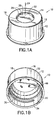
- FIG. 1A is top perspective view of the two-piece cap assembly of the present invention.
- FIG. 1B is a bottom perspective view of the cap assembly of FIG. 1A.
- FIG. 2A is a top perspective view of the cap body of the inventive cap assembly.
- FIG. 2B is bottom perspective view of the cap body of FIG. 2A.
- FIG. 3A is a top perspective view of the plug seal component of the inventive cap assembly.
- FIG. 3B is a bottom perspective view of the plug seal of FIG. 3A.
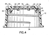
- FIG. 4 is a cross-sectional showing of the cap assembly of the present invention.
- FIGS. 1A and 1B show a cap assembly for closing the liquid opening in a neck portion of a container in accordance with the present invention.
- FIGS. 1A and 1B show a roller bottle cap assembly 10 .
- cap assembly 10 includes a cap body 12 having a top wall 14 and a depending annular skirt 16 for screw attachment to the neck portion of a roller bottle, and further includes plug seal 18 which is attachable to the underside 20 of cap body 12 .
- Plug seal 18 and cap body 12 are relatively rotatably coupled for independent rotation of the cap body 12 with respect to plug seal 18 upon attachment and removal of the cap assembly 10 from the neck portion of the roller bottle or other container.
- plug seal 18 is free to rotate about cap body axis 24 , so that rather than rubbing against the inner rim of the bottle as the cap body rotates, it simply moves up or down as the cap body moves up or down.
- the cap body 12 of the inventive cap assembly includes a central orifice 22 for accommodating plug seal component 18 .
- the orifice 22 may be stepped to help provide a snap-fit with plug seal 18 .
- annular skirt 16 of cap body 12 includes an inner wall 30 and an outer wall 32 .
- the inner wall 30 may include threads 34 for removably attaching the cap assembly 10 from the neck portion of the container.
- outer wall 32 of annual skirt 16 may include vertical ribs 36 to improve the user's grip during attachment and detachment of the cap.
- Inner wall 30 may include a locking arrangement 38 , as shown in FIG. 2B, for holding the cap assembly in a locked open position on the roller bottle for maintaining the roller bottle open to the environment surrounding it.
- the underside of top wall 14 of cap body 12 preferably includes two projecting rings 39 which reduce surface contact between cap body 12 and plug seal 18 . Desirably, such rings are integrally formed with the cap.
- top surface 26 of plug seal 18 includes flanges 28 to provide a snap-fit attachment to the underside of the cap body.
- Flanges 28 may be integrally formed with top surface 26 of plug seal 18 and are configured in an annular ring for association with orifice 22 . As needed, the orifice may be stepped to help provide the snap-fit, as described above.
- top surface 26 of plug seal component 18 cap assembly 10 includes an annular groove 40 to help further provide a snap-fit attachment with cap body 12 .
- top wall 14 of cap body 12 may include depending annular projections 42 spaced radially from depending annual skirt 16 to help provide a snap-fit with the annular groove 40 of plug seal 18 .
- bottom surface 44 of plug seal component 18 includes tabs 46 in a spaced annular arrangement for insertion of a device (not shown) to form a vented cap assembly.
- the tabs 46 may permit attachment of a gas-permeable membrane to permit free passage of oxygen and carbon dioxide while preventing passage of bacteria and fungi into the roller bottle.
- Suitable gas-permeable membranes can be made of materials such as polyethylene, polycarbonate, acrylic co-polymers and polytetrafluoroethylene.
- thermoplastic materials including, for example, polystyrene, polyethylene terephthalate, the polyolefins and polyvinylchloride.
- the sealing mechanism of the present invention rotates independently about the axis of the cap.
- the sealing mechanism does not rotate as the cap rotates, thereby eliminating the friction normally occurring when the sealing mechanism rubs against the container rim as it rotates with the cap. Therefore, lower torque is required to attach and detach the cap from the container.
- the user was required to rotate the cap and grind the dried media against the sealing surface as the sealing surface rotated against the inner bottle rim.
- the sealing surface is lifted free of the crusted media at the bottle rim, rather than grinding against it as the cap rotates.
- the cap assembly of the invention is particularly useful for closing the liquid opening of cell culture vessels, such as roller bottles and flasks
- inventive cap assembly would be useful for closure of an opening in a neck portion of a centrifuge tube or bottle, where it is important that the user not be required to apply a large amount of torque to attach and detach the cap.
- the cap assembly of the invention following centrifugation, there may be discrete layers of separated components in the liquid medium which have less chance of intermixing in situations where the user applies a low amount of torque when detaching the cap and retrieving the separated components from the centrifuge tube or bottle.
Landscapes
- Health & Medical Sciences (AREA)
- Chemical & Material Sciences (AREA)
- Zoology (AREA)
- Clinical Laboratory Science (AREA)
- Life Sciences & Earth Sciences (AREA)
- Engineering & Computer Science (AREA)
- Bioinformatics & Cheminformatics (AREA)
- Organic Chemistry (AREA)
- General Health & Medical Sciences (AREA)
- Wood Science & Technology (AREA)
- Biomedical Technology (AREA)
- Sustainable Development (AREA)
- Biochemistry (AREA)
- General Engineering & Computer Science (AREA)
- Microbiology (AREA)
- Genetics & Genomics (AREA)
- Biotechnology (AREA)
- Analytical Chemistry (AREA)
- Hematology (AREA)
- Chemical Kinetics & Catalysis (AREA)
- Closures For Containers (AREA)
- Rolls And Other Rotary Bodies (AREA)
Abstract
Description
Claims (10)
- A cap assembly for closing the opening in a neck portion of a container comprising:a cap body having a top wall and a depending annular skirt for screw attachment to said neck portion of said container;a plug seal attachable to an undersurface of said top wall of said cap body,said plug seal and said cap body being relatively rotatably coupled for independent rotation of said cap body with respect to said plug seal upon attachment and removal of said cap assembly from said neck portion of said container.
- The assembly of claim 1, wherein said plug seal is free to rotate about the longitudinal axis of said cap body.
- The assembly of claim 1, wherein said cap body includes a central orifice for accommodating said plug seal.
- The assembly of claim 3, wherein said orifice is stepped to assist in providing snap-fit attachment with said plug seal.
- The assembly of claim 3, wherein said plug seal includes flanges which are integrally formed with a top surface of said plug seal to assist in providing a snap-fit attachment with said cap body.
- The assembly of claim 5, wherein said flanges are configured in a discontinuous annular ring for association with said central orifice of said cap body.
- The assembly of claim 1, wherein said plug seal further includes an annular groove.
- The assembly of claim 7, wherein said top wall of said cap body includes at least one depending projection spaced radially from said depending annular skirt of said cap body to be received in said annular groove of said plug seal.
- The assembly of claim 8, wherein said projection is annular.
- The assembly of claim 8, wherein said projection is discontinuous.
Applications Claiming Priority (2)
| Application Number | Priority Date | Filing Date | Title |
|---|---|---|---|
| US41235602P | 2002-09-20 | 2002-09-20 | |
| US412356P | 2002-09-20 |
Publications (3)
| Publication Number | Publication Date |
|---|---|
| EP1400283A2 true EP1400283A2 (en) | 2004-03-24 |
| EP1400283A3 EP1400283A3 (en) | 2005-07-06 |
| EP1400283B1 EP1400283B1 (en) | 2009-11-18 |
Family
ID=31946985
Family Applications (1)
| Application Number | Title | Priority Date | Filing Date |
|---|---|---|---|
| EP03021217A Expired - Lifetime EP1400283B1 (en) | 2002-09-20 | 2003-09-18 | Roller bottle |
Country Status (5)
| Country | Link |
|---|---|
| US (1) | US7163115B2 (en) |
| EP (1) | EP1400283B1 (en) |
| JP (1) | JP4422996B2 (en) |
| AT (1) | ATE448877T1 (en) |
| DE (1) | DE60330100D1 (en) |
Cited By (5)
| Publication number | Priority date | Publication date | Assignee | Title |
|---|---|---|---|---|
| EP2242702A4 (en) * | 2008-01-11 | 2012-08-08 | Ball Corp | Method and apparatus for providing a positive pressure in the headspace of a plastic container |
| WO2014022229A1 (en) | 2012-07-31 | 2014-02-06 | National Scientific Company | Vial closure with septum retention feature |
| WO2014063948A1 (en) * | 2012-10-23 | 2014-05-01 | Rpc Formatec Gmbh | Vessel |
| US8985359B2 (en) | 2011-03-28 | 2015-03-24 | Corning Incorporated | Container cap with kink-resistant connector |
| CN105667977A (en) * | 2016-01-26 | 2016-06-15 | 马宁 | Cylinder cover for ink storage tank |
Families Citing this family (12)
| Publication number | Priority date | Publication date | Assignee | Title |
|---|---|---|---|---|
| WO2005011495A1 (en) * | 2003-07-18 | 2005-02-10 | Sekisui Chemical Co., Ltd. | Hermetically sealed container and vacuum test substance-collecting container |
| JP2006076575A (en) * | 2004-09-07 | 2006-03-23 | Mitsubishi Materials Corp | Cap material, cap and bottle can with cap |
| ITBO20050483A1 (en) * | 2005-07-19 | 2007-01-20 | Brev Angela Srl | PERFORTABLE CLOSURE FOR A CONTAINER, MOLD AND METHOD TO REALIZE IT |
| DE102005034178A1 (en) * | 2005-07-21 | 2006-07-27 | Adelholzener Alpenquellen Gmbh | Device for storing a liquid enriched with carbon dioxide and/or oxygen comprises a sealing body having a projection and a closure having a toothed element which interacts with the projection in a detachable manner |
| WO2007071287A1 (en) * | 2005-12-22 | 2007-06-28 | Pentacore International Holding Bv | Laboratory cultutre flask with snap-on cap |
| US7874441B2 (en) * | 2007-03-01 | 2011-01-25 | Rexam Closure Systems Inc. | Closure and package for high-temperature applications |
| EP2303581B1 (en) * | 2008-05-29 | 2014-10-08 | Hewlett-Packard Development Company, L.P. | Cap for a fluid container outlet |
| FR2972429B1 (en) * | 2011-03-09 | 2013-04-05 | Tetra Laval Holdings & Finance | DEVICE FOR CLOSING A CONTAINER COLLAR |
| US9075039B2 (en) | 2011-11-08 | 2015-07-07 | Becton, Dickinson And Company | Container and cap for a biological specimen |
| US9381524B2 (en) | 2011-11-08 | 2016-07-05 | Becton, Dickinson And Company | System and method for automated sample preparation |
| KR200470347Y1 (en) * | 2012-01-31 | 2013-12-11 | 주식회사 한국인삼공사 | Cap having rotating type sealing member |
| US10633150B2 (en) * | 2017-12-04 | 2020-04-28 | Bucktap Llc | Pour spout device |
Family Cites Families (28)
| Publication number | Priority date | Publication date | Assignee | Title |
|---|---|---|---|---|
| US1985703A (en) * | 1933-07-29 | 1934-12-25 | Owens Illinois Glass Co | Capillary applicator rod |
| US3499568A (en) * | 1967-12-28 | 1970-03-10 | Jose Vinas Riera | Stopper system for biological containers |
| US3709395A (en) * | 1971-07-01 | 1973-01-09 | Hospital Service Technology Co | Closure for containers |
| IT1007292B (en) * | 1974-02-08 | 1976-10-30 | Fidenza Vetraria Spa | LID WITH HERMETIC CLOSURE FOR CONTAINERS |
| US4128184A (en) * | 1978-05-15 | 1978-12-05 | Northup John D | Child-proof container and cap |
| DE3071963D1 (en) * | 1979-11-02 | 1987-06-11 | Labco Limited | Blood sampling sets |
| US4462502A (en) * | 1980-12-22 | 1984-07-31 | Ethyl Molded Products Company | Threaded closure with liner |
| US4423821A (en) * | 1981-09-23 | 1984-01-03 | Mack-Wayne Plastics Company | Stress failure resistant container cap |
| US4747500A (en) * | 1985-01-22 | 1988-05-31 | Sunbeam Plastics Corporation | Tamper indicating transparent closure |
| JP2620554B2 (en) * | 1988-03-04 | 1997-06-18 | 日本クラウンコルク株式会社 | Composite container lid |
| WO1991001238A1 (en) | 1989-07-14 | 1991-02-07 | Loevinger Richard P | Heated tank car with discharge valve and pressure equalizer |
| US5092477A (en) * | 1991-06-14 | 1992-03-03 | Johnson Jr John C | Container closure |
| KR0119874Y1 (en) * | 1993-03-02 | 1998-06-01 | 이용학 | Synthetic resin sealing cap for a fluid bottle |
| EP0614967A3 (en) * | 1993-03-09 | 1996-10-16 | Becton Dickinson Co | Three piece roller bottle assembly for culturing cells having multiple longitudinal elements on the interior surface. |
| US5358872A (en) * | 1993-08-12 | 1994-10-25 | Becton, Dickinson And Company | Vessel and closure assembly |
| US5391496A (en) * | 1993-09-01 | 1995-02-21 | Becton, Dickinson And Company | Culturing vessel and closure assembly |
| US5755269A (en) * | 1993-12-09 | 1998-05-26 | Ciba Corning Diagnostics Corp. | Fluid delivery system |
| JP2943048B2 (en) * | 1994-08-06 | 1999-08-30 | 日本山村硝子株式会社 | Pill fur proof cap made of synthetic resin |
| US5595907A (en) * | 1995-09-08 | 1997-01-21 | Becton, Dickinson And Company | Reusable vented flask cap cover |
| US5578491A (en) * | 1995-09-08 | 1996-11-26 | Becton, Dickinson And Company | Reusable vented flask cap cover |
| US5766936A (en) * | 1995-09-08 | 1998-06-16 | Becton Dickinson And Company | Reusable vented flask cap cover |
| US5622865A (en) * | 1995-09-08 | 1997-04-22 | Becton, Dickinson And Company | Reusable vented flask cap cover |
| US5695987A (en) * | 1996-08-08 | 1997-12-09 | Becton Dickinson And Company | Reusable vented flask cap cover |
| EP0987191A1 (en) * | 1998-09-14 | 2000-03-22 | Crown Cork & Seal Technologies Corporation | Closure cap |
| EP1066881A3 (en) * | 1999-07-09 | 2002-07-03 | Becton Dickinson and Company | Specimen collection assembly with cap |
| BR0113969B1 (en) * | 2000-09-20 | 2012-02-07 | plastic vent closure and method of bottling a drink. | |
| WO2002072265A1 (en) * | 2001-03-09 | 2002-09-19 | Gen-Probe Incorporated | Penetrable cap |
| US6874647B2 (en) * | 2002-08-12 | 2005-04-05 | Owens-Illinois Closure Inc. | Plastic closure, closure and container package, and method of manufacture |
-
2003
- 2003-09-18 EP EP03021217A patent/EP1400283B1/en not_active Expired - Lifetime
- 2003-09-18 DE DE60330100T patent/DE60330100D1/en not_active Expired - Lifetime
- 2003-09-18 AT AT03021217T patent/ATE448877T1/en not_active IP Right Cessation
- 2003-09-19 US US10/667,007 patent/US7163115B2/en not_active Expired - Lifetime
- 2003-09-22 JP JP2003330629A patent/JP4422996B2/en not_active Expired - Fee Related
Cited By (8)
| Publication number | Priority date | Publication date | Assignee | Title |
|---|---|---|---|---|
| EP2242702A4 (en) * | 2008-01-11 | 2012-08-08 | Ball Corp | Method and apparatus for providing a positive pressure in the headspace of a plastic container |
| US8342344B2 (en) | 2008-01-11 | 2013-01-01 | Amcor Rigid Plastics Usa, Inc. | Method and apparatus for providing a positive pressure in the headspace of a plastic container |
| US8985359B2 (en) | 2011-03-28 | 2015-03-24 | Corning Incorporated | Container cap with kink-resistant connector |
| WO2014022229A1 (en) | 2012-07-31 | 2014-02-06 | National Scientific Company | Vial closure with septum retention feature |
| CN104736248A (en) * | 2012-07-31 | 2015-06-24 | 国家科技公司 | Vial closure with septum retention feature |
| EP2879795A4 (en) * | 2012-07-31 | 2016-03-30 | Nat Scient Co | BOTTLE CLOSURE HAVING A SEPTUM RETENTION CHARACTERISTIC |
| WO2014063948A1 (en) * | 2012-10-23 | 2014-05-01 | Rpc Formatec Gmbh | Vessel |
| CN105667977A (en) * | 2016-01-26 | 2016-06-15 | 马宁 | Cylinder cover for ink storage tank |
Also Published As
| Publication number | Publication date |
|---|---|
| JP2004269046A (en) | 2004-09-30 |
| EP1400283B1 (en) | 2009-11-18 |
| ATE448877T1 (en) | 2009-12-15 |
| US7163115B2 (en) | 2007-01-16 |
| DE60330100D1 (en) | 2009-12-31 |
| JP4422996B2 (en) | 2010-03-03 |
| US20040099629A1 (en) | 2004-05-27 |
| EP1400283A3 (en) | 2005-07-06 |
Similar Documents
| Publication | Publication Date | Title |
|---|---|---|
| US7163115B2 (en) | Roller bottle cap | |
| US5316163A (en) | Bottle top having inner and outer caps for securing and sealing a resilient stopper | |
| US5954215A (en) | Leak-proof container | |
| US5398837A (en) | Cell culture flask and closure | |
| US5899349A (en) | Cap/closure having a venting mechanism for use with centrifuge containers | |
| JP2610396B2 (en) | Assembly of container and closure member | |
| US4993573A (en) | Bottle closure | |
| US7918363B2 (en) | Resealable beverage container | |
| US5455180A (en) | Container closure of medical tests | |
| MX2008010308A (en) | Container assembly and pressure-responsive penetrable cap for the same. | |
| JP2009073570A (en) | Cap of container for centrifugal separator, and cap assembly | |
| CA1191481A (en) | Child-proof closure | |
| EP0102851B1 (en) | A closure for a container | |
| EP0761811B1 (en) | Reusable vented flask cap cover | |
| US20080308554A1 (en) | Packaging Article | |
| US4103798A (en) | Combination cap | |
| US5947309A (en) | Container-closure combination with improved sealing feature | |
| CA2057907C (en) | Plastic closure with improved seal | |
| EP1021250B1 (en) | Centrifugally loaded self-sealing integral one-piece cap/closure | |
| GB2084549A (en) | Opener for screw-tops | |
| JP4049837B2 (en) | Culture vessel assembly | |
| US3933267A (en) | Container closure assembly | |
| GB2046719A (en) | Sealing bung for container closures | |
| AU718368B2 (en) | Resuable vented flask cap cover | |
| CN210285001U (en) | Non-toxic sealed glass jar |
Legal Events
| Date | Code | Title | Description |
|---|---|---|---|
| PUAI | Public reference made under article 153(3) epc to a published international application that has entered the european phase |
Free format text: ORIGINAL CODE: 0009012 |
|
| AK | Designated contracting states |
Kind code of ref document: A2 Designated state(s): AT BE BG CH CY CZ DE DK EE ES FI FR GB GR HU IE IT LI LU MC NL PT RO SE SI SK TR |
|
| AX | Request for extension of the european patent |
Extension state: AL LT LV MK |
|
| PUAL | Search report despatched |
Free format text: ORIGINAL CODE: 0009013 |
|
| AK | Designated contracting states |
Kind code of ref document: A3 Designated state(s): AT BE BG CH CY CZ DE DK EE ES FI FR GB GR HU IE IT LI LU MC NL PT RO SE SI SK TR |
|
| AX | Request for extension of the european patent |
Extension state: AL LT LV MK |
|
| RIC1 | Information provided on ipc code assigned before grant |
Ipc: 7C 12M 1/10 B Ipc: 7C 12M 3/04 B Ipc: 7B 01L 3/14 A Ipc: 7C 12M 1/00 B |
|
| 17P | Request for examination filed |
Effective date: 20051124 |
|
| AKX | Designation fees paid |
Designated state(s): AT BE BG CH CY CZ DE DK EE ES FI FR GB GR HU IE IT LI LU MC NL PT RO SE SI SK TR |
|
| GRAP | Despatch of communication of intention to grant a patent |
Free format text: ORIGINAL CODE: EPIDOSNIGR1 |
|
| GRAS | Grant fee paid |
Free format text: ORIGINAL CODE: EPIDOSNIGR3 |
|
| GRAA | (expected) grant |
Free format text: ORIGINAL CODE: 0009210 |
|
| AK | Designated contracting states |
Kind code of ref document: B1 Designated state(s): AT BE BG CH CY CZ DE DK EE ES FI FR GB GR HU IE IT LI LU MC NL PT RO SE SI SK TR |
|
| REG | Reference to a national code |
Ref country code: GB Ref legal event code: FG4D |
|
| REG | Reference to a national code |
Ref country code: CH Ref legal event code: NV Representative=s name: ISLER & PEDRAZZINI AG Ref country code: CH Ref legal event code: EP |
|
| REG | Reference to a national code |
Ref country code: IE Ref legal event code: FG4D |
|
| REF | Corresponds to: |
Ref document number: 60330100 Country of ref document: DE Date of ref document: 20091231 Kind code of ref document: P |
|
| REG | Reference to a national code |
Ref country code: NL Ref legal event code: VDEP Effective date: 20091118 |
|
| PG25 | Lapsed in a contracting state [announced via postgrant information from national office to epo] |
Ref country code: PT Free format text: LAPSE BECAUSE OF FAILURE TO SUBMIT A TRANSLATION OF THE DESCRIPTION OR TO PAY THE FEE WITHIN THE PRESCRIBED TIME-LIMIT Effective date: 20100318 Ref country code: ES Free format text: LAPSE BECAUSE OF FAILURE TO SUBMIT A TRANSLATION OF THE DESCRIPTION OR TO PAY THE FEE WITHIN THE PRESCRIBED TIME-LIMIT Effective date: 20100228 Ref country code: SE Free format text: LAPSE BECAUSE OF FAILURE TO SUBMIT A TRANSLATION OF THE DESCRIPTION OR TO PAY THE FEE WITHIN THE PRESCRIBED TIME-LIMIT Effective date: 20091118 Ref country code: FI Free format text: LAPSE BECAUSE OF FAILURE TO SUBMIT A TRANSLATION OF THE DESCRIPTION OR TO PAY THE FEE WITHIN THE PRESCRIBED TIME-LIMIT Effective date: 20091118 |
|
| PG25 | Lapsed in a contracting state [announced via postgrant information from national office to epo] |
Ref country code: SI Free format text: LAPSE BECAUSE OF FAILURE TO SUBMIT A TRANSLATION OF THE DESCRIPTION OR TO PAY THE FEE WITHIN THE PRESCRIBED TIME-LIMIT Effective date: 20091118 Ref country code: CY Free format text: LAPSE BECAUSE OF FAILURE TO SUBMIT A TRANSLATION OF THE DESCRIPTION OR TO PAY THE FEE WITHIN THE PRESCRIBED TIME-LIMIT Effective date: 20091118 |
|
| PG25 | Lapsed in a contracting state [announced via postgrant information from national office to epo] |
Ref country code: BE Free format text: LAPSE BECAUSE OF FAILURE TO SUBMIT A TRANSLATION OF THE DESCRIPTION OR TO PAY THE FEE WITHIN THE PRESCRIBED TIME-LIMIT Effective date: 20091118 Ref country code: AT Free format text: LAPSE BECAUSE OF FAILURE TO SUBMIT A TRANSLATION OF THE DESCRIPTION OR TO PAY THE FEE WITHIN THE PRESCRIBED TIME-LIMIT Effective date: 20091118 |
|
| PG25 | Lapsed in a contracting state [announced via postgrant information from national office to epo] |
Ref country code: DK Free format text: LAPSE BECAUSE OF FAILURE TO SUBMIT A TRANSLATION OF THE DESCRIPTION OR TO PAY THE FEE WITHIN THE PRESCRIBED TIME-LIMIT Effective date: 20091118 Ref country code: BG Free format text: LAPSE BECAUSE OF FAILURE TO SUBMIT A TRANSLATION OF THE DESCRIPTION OR TO PAY THE FEE WITHIN THE PRESCRIBED TIME-LIMIT Effective date: 20100218 Ref country code: RO Free format text: LAPSE BECAUSE OF FAILURE TO SUBMIT A TRANSLATION OF THE DESCRIPTION OR TO PAY THE FEE WITHIN THE PRESCRIBED TIME-LIMIT Effective date: 20091118 Ref country code: NL Free format text: LAPSE BECAUSE OF FAILURE TO SUBMIT A TRANSLATION OF THE DESCRIPTION OR TO PAY THE FEE WITHIN THE PRESCRIBED TIME-LIMIT Effective date: 20091118 Ref country code: EE Free format text: LAPSE BECAUSE OF FAILURE TO SUBMIT A TRANSLATION OF THE DESCRIPTION OR TO PAY THE FEE WITHIN THE PRESCRIBED TIME-LIMIT Effective date: 20091118 |
|
| PG25 | Lapsed in a contracting state [announced via postgrant information from national office to epo] |
Ref country code: CZ Free format text: LAPSE BECAUSE OF FAILURE TO SUBMIT A TRANSLATION OF THE DESCRIPTION OR TO PAY THE FEE WITHIN THE PRESCRIBED TIME-LIMIT Effective date: 20091118 Ref country code: SK Free format text: LAPSE BECAUSE OF FAILURE TO SUBMIT A TRANSLATION OF THE DESCRIPTION OR TO PAY THE FEE WITHIN THE PRESCRIBED TIME-LIMIT Effective date: 20091118 |
|
| PLBE | No opposition filed within time limit |
Free format text: ORIGINAL CODE: 0009261 |
|
| STAA | Information on the status of an ep patent application or granted ep patent |
Free format text: STATUS: NO OPPOSITION FILED WITHIN TIME LIMIT |
|
| 26N | No opposition filed |
Effective date: 20100819 |
|
| PG25 | Lapsed in a contracting state [announced via postgrant information from national office to epo] |
Ref country code: GR Free format text: LAPSE BECAUSE OF FAILURE TO SUBMIT A TRANSLATION OF THE DESCRIPTION OR TO PAY THE FEE WITHIN THE PRESCRIBED TIME-LIMIT Effective date: 20100219 |
|
| PG25 | Lapsed in a contracting state [announced via postgrant information from national office to epo] |
Ref country code: MC Free format text: LAPSE BECAUSE OF NON-PAYMENT OF DUE FEES Effective date: 20100930 |
|
| PG25 | Lapsed in a contracting state [announced via postgrant information from national office to epo] |
Ref country code: IE Free format text: LAPSE BECAUSE OF NON-PAYMENT OF DUE FEES Effective date: 20100918 |
|
| PG25 | Lapsed in a contracting state [announced via postgrant information from national office to epo] |
Ref country code: LU Free format text: LAPSE BECAUSE OF NON-PAYMENT OF DUE FEES Effective date: 20100918 Ref country code: HU Free format text: LAPSE BECAUSE OF FAILURE TO SUBMIT A TRANSLATION OF THE DESCRIPTION OR TO PAY THE FEE WITHIN THE PRESCRIBED TIME-LIMIT Effective date: 20100519 |
|
| PG25 | Lapsed in a contracting state [announced via postgrant information from national office to epo] |
Ref country code: TR Free format text: LAPSE BECAUSE OF FAILURE TO SUBMIT A TRANSLATION OF THE DESCRIPTION OR TO PAY THE FEE WITHIN THE PRESCRIBED TIME-LIMIT Effective date: 20091118 |
|
| REG | Reference to a national code |
Ref country code: FR Ref legal event code: PLFP Year of fee payment: 14 |
|
| REG | Reference to a national code |
Ref country code: FR Ref legal event code: PLFP Year of fee payment: 15 |
|
| REG | Reference to a national code |
Ref country code: FR Ref legal event code: PLFP Year of fee payment: 16 |
|
| PGFP | Annual fee paid to national office [announced via postgrant information from national office to epo] |
Ref country code: FR Payment date: 20190820 Year of fee payment: 17 Ref country code: DE Payment date: 20190820 Year of fee payment: 17 Ref country code: IT Payment date: 20190829 Year of fee payment: 17 |
|
| PGFP | Annual fee paid to national office [announced via postgrant information from national office to epo] |
Ref country code: GB Payment date: 20190820 Year of fee payment: 17 |
|
| PGFP | Annual fee paid to national office [announced via postgrant information from national office to epo] |
Ref country code: CH Payment date: 20190820 Year of fee payment: 17 |
|
| REG | Reference to a national code |
Ref country code: DE Ref legal event code: R119 Ref document number: 60330100 Country of ref document: DE |
|
| REG | Reference to a national code |
Ref country code: CH Ref legal event code: PL |
|
| GBPC | Gb: european patent ceased through non-payment of renewal fee |
Effective date: 20200918 |
|
| PG25 | Lapsed in a contracting state [announced via postgrant information from national office to epo] |
Ref country code: DE Free format text: LAPSE BECAUSE OF NON-PAYMENT OF DUE FEES Effective date: 20210401 Ref country code: FR Free format text: LAPSE BECAUSE OF NON-PAYMENT OF DUE FEES Effective date: 20200930 |
|
| PG25 | Lapsed in a contracting state [announced via postgrant information from national office to epo] |
Ref country code: CH Free format text: LAPSE BECAUSE OF NON-PAYMENT OF DUE FEES Effective date: 20200930 Ref country code: LI Free format text: LAPSE BECAUSE OF NON-PAYMENT OF DUE FEES Effective date: 20200930 Ref country code: GB Free format text: LAPSE BECAUSE OF NON-PAYMENT OF DUE FEES Effective date: 20200918 |
|
| PG25 | Lapsed in a contracting state [announced via postgrant information from national office to epo] |
Ref country code: IT Free format text: LAPSE BECAUSE OF NON-PAYMENT OF DUE FEES Effective date: 20200918 |