EP1398894A2 - Light amplifying apparatus for wavelength division multiplexing capable for determining change in number of multiplexed wavelength signals - Google Patents
Light amplifying apparatus for wavelength division multiplexing capable for determining change in number of multiplexed wavelength signals Download PDFInfo
- Publication number
- EP1398894A2 EP1398894A2 EP03255109A EP03255109A EP1398894A2 EP 1398894 A2 EP1398894 A2 EP 1398894A2 EP 03255109 A EP03255109 A EP 03255109A EP 03255109 A EP03255109 A EP 03255109A EP 1398894 A2 EP1398894 A2 EP 1398894A2
- Authority
- EP
- European Patent Office
- Prior art keywords
- photo
- light power
- wavelengths
- amplifying apparatus
- measured
- Prior art date
- Legal status (The legal status is an assumption and is not a legal conclusion. Google has not performed a legal analysis and makes no representation as to the accuracy of the status listed.)
- Granted
Links
Images






Classifications
-
- H—ELECTRICITY
- H04—ELECTRIC COMMUNICATION TECHNIQUE
- H04B—TRANSMISSION
- H04B10/00—Transmission systems employing electromagnetic waves other than radio-waves, e.g. infrared, visible or ultraviolet light, or employing corpuscular radiation, e.g. quantum communication
- H04B10/29—Repeaters
- H04B10/291—Repeaters in which processing or amplification is carried out without conversion of the main signal from optical form
- H04B10/293—Signal power control
- H04B10/294—Signal power control in a multiwavelength system, e.g. gain equalisation
- H04B10/296—Transient power control, e.g. due to channel add/drop or rapid fluctuations in the input power
-
- H—ELECTRICITY
- H01—ELECTRIC ELEMENTS
- H01S—DEVICES USING THE PROCESS OF LIGHT AMPLIFICATION BY STIMULATED EMISSION OF RADIATION [LASER] TO AMPLIFY OR GENERATE LIGHT; DEVICES USING STIMULATED EMISSION OF ELECTROMAGNETIC RADIATION IN WAVE RANGES OTHER THAN OPTICAL
- H01S3/00—Lasers, i.e. devices using stimulated emission of electromagnetic radiation in the infrared, visible or ultraviolet wave range
- H01S3/05—Construction or shape of optical resonators; Accommodation of active medium therein; Shape of active medium
- H01S3/06—Construction or shape of active medium
- H01S3/063—Waveguide lasers, i.e. whereby the dimensions of the waveguide are of the order of the light wavelength
- H01S3/067—Fibre lasers
- H01S3/06754—Fibre amplifiers
- H01S3/06758—Tandem amplifiers
-
- H—ELECTRICITY
- H01—ELECTRIC ELEMENTS
- H01S—DEVICES USING THE PROCESS OF LIGHT AMPLIFICATION BY STIMULATED EMISSION OF RADIATION [LASER] TO AMPLIFY OR GENERATE LIGHT; DEVICES USING STIMULATED EMISSION OF ELECTROMAGNETIC RADIATION IN WAVE RANGES OTHER THAN OPTICAL
- H01S3/00—Lasers, i.e. devices using stimulated emission of electromagnetic radiation in the infrared, visible or ultraviolet wave range
- H01S3/10—Controlling the intensity, frequency, phase, polarisation or direction of the emitted radiation, e.g. switching, gating, modulating or demodulating
- H01S3/13—Stabilisation of laser output parameters, e.g. frequency or amplitude
- H01S3/1301—Stabilisation of laser output parameters, e.g. frequency or amplitude in optical amplifiers
-
- H—ELECTRICITY
- H01—ELECTRIC ELEMENTS
- H01S—DEVICES USING THE PROCESS OF LIGHT AMPLIFICATION BY STIMULATED EMISSION OF RADIATION [LASER] TO AMPLIFY OR GENERATE LIGHT; DEVICES USING STIMULATED EMISSION OF ELECTROMAGNETIC RADIATION IN WAVE RANGES OTHER THAN OPTICAL
- H01S3/00—Lasers, i.e. devices using stimulated emission of electromagnetic radiation in the infrared, visible or ultraviolet wave range
- H01S3/10—Controlling the intensity, frequency, phase, polarisation or direction of the emitted radiation, e.g. switching, gating, modulating or demodulating
- H01S3/13—Stabilisation of laser output parameters, e.g. frequency or amplitude
- H01S3/1301—Stabilisation of laser output parameters, e.g. frequency or amplitude in optical amplifiers
- H01S3/13013—Stabilisation of laser output parameters, e.g. frequency or amplitude in optical amplifiers by controlling the optical pumping
-
- H—ELECTRICITY
- H04—ELECTRIC COMMUNICATION TECHNIQUE
- H04J—MULTIPLEX COMMUNICATION
- H04J14/00—Optical multiplex systems
- H04J14/02—Wavelength-division multiplex systems
- H04J14/0221—Power control, e.g. to keep the total optical power constant
- H04J14/02216—Power control, e.g. to keep the total optical power constant by gain equalization
-
- H—ELECTRICITY
- H01—ELECTRIC ELEMENTS
- H01S—DEVICES USING THE PROCESS OF LIGHT AMPLIFICATION BY STIMULATED EMISSION OF RADIATION [LASER] TO AMPLIFY OR GENERATE LIGHT; DEVICES USING STIMULATED EMISSION OF ELECTROMAGNETIC RADIATION IN WAVE RANGES OTHER THAN OPTICAL
- H01S2301/00—Functional characteristics
- H01S2301/04—Gain spectral shaping, flattening
-
- H—ELECTRICITY
- H01—ELECTRIC ELEMENTS
- H01S—DEVICES USING THE PROCESS OF LIGHT AMPLIFICATION BY STIMULATED EMISSION OF RADIATION [LASER] TO AMPLIFY OR GENERATE LIGHT; DEVICES USING STIMULATED EMISSION OF ELECTROMAGNETIC RADIATION IN WAVE RANGES OTHER THAN OPTICAL
- H01S3/00—Lasers, i.e. devices using stimulated emission of electromagnetic radiation in the infrared, visible or ultraviolet wave range
- H01S3/10—Controlling the intensity, frequency, phase, polarisation or direction of the emitted radiation, e.g. switching, gating, modulating or demodulating
- H01S3/10007—Controlling the intensity, frequency, phase, polarisation or direction of the emitted radiation, e.g. switching, gating, modulating or demodulating in optical amplifiers
- H01S3/10015—Controlling the intensity, frequency, phase, polarisation or direction of the emitted radiation, e.g. switching, gating, modulating or demodulating in optical amplifiers by monitoring or controlling, e.g. attenuating, the input signal
Definitions
- the present invention generally relates to a photo (light) amplifying apparatus, and more particularly, to a photo amplifying apparatus for amplifying wavelength division multiplexing (WDM) signals that includes a measuring unit that measures the power of a specific wavelength, a measuring unit that measures the total power of all wavelengths, and a controlling unit that controls the output power of the photo amplifying apparatus.
- WDM wavelength division multiplexing
- Wavelength division multiplexing is a pervading broad band technology in which a plurality of photo signals of different wavelengths is transmitted via a single optical transmission path.
- wavelength division multiplexing technology is applied to multi-channel optical communications of various distances.
- wavelength division multiplexing communication systems are required to flexibly support optical communications of various wavelengths and distances.
- a WDM photo amplifying apparatus of the WDM communication system amplifies photo signals so that the output power of output photo signals of each wavelength becomes equal.
- the WDM photo amplifying apparatus controls excitation light sources and optical attenuators provided therein based on information about the power of photo signals monitored at various stages in the optical path and information for setting gain, the number of wavelengths, and output power, for example, received from an exterior resource.
- FIG. 1 is a schematic diagram showing a conventional photo amplifying apparatus.
- the photo amplifying apparatus shown in FIG. 1 includes photo amplifying units 1, 2, a variable optical attenuator 6, a control unit 7, optical splitters 12-15, and photo diodes (optical monitors) 32-35.
- the photo amplifying units 1, 2 further include Erbium-doped Fiber Amplifiers (EDFA) 3, 4, laser diodes (excitation light sources) 21, 22, and wavelength mixers 41, 42, respectively.
- the photo amplifying unit 1 further includes a gain equalizer 5.
- the EDFAs 3, 4 are excited by the laser diodes 21, 22, respectively.
- FIG. 2 is a graph showing the distribution of power (dBm) over wavelength (nm) of wavelength division multiplexing signals.
- X in denotes the power of photo signals of each wavelength ⁇ 1- ⁇ n.
- the WDM signal having the power distribution shown in FIG. 2 is input to the photo amplifying apparatus via a input terminal IN.
- a fraction of the input photo signals is split from the main signal by the photo splitter (photo coupler) 12, and converted into an electric signal by the photo diode 32.
- FIG. 3 is a schematic diagram showing the power of the photo signals monitored by the photo diode 32.
- the outputs of the photo diodes 33-35 depend only on the total power of photo signals over all wavelengths ⁇ 1- ⁇ n incoming to the photo splitters 13-15, respectively.
- the control unit 7 controls the power of each stage based on the total power of the photo signals over all wavelengths ⁇ 1- ⁇ n monitored by the photo diodes 32-35. As a result, the photo amplifying apparatus shown in FIG. 1 outputs the objective output photo signals via an output terminal OUT.
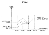
- FIG. 4 is a schematic diagram for explaining the automatic level control (ALC) performed by the control unit 7.
- the control unit 7 of the photo amplifying apparatus shown in FIG. 1 automatically controls the optical level of each stage as follows:
- FIGS. 5A and 5B are schematic diagrams for explaining a problem that occurs in the case wherein the control unit 7 fails to control the output from the output terminal OUT at the level determined based on the number of wavelengths.
- FIG. 5A illustrates the case wherein two wavelengths are used.
- the output powers of both wavelengths ⁇ 1, ⁇ 2 are assumed to be equal to the same value X in . Under such a condition, the case in which the light source of the wavelength ⁇ 2 accidentally malfunctions is examined below.
- the output level of the photo amplifying apparatus is expected to be halved.
- the control unit 7 compensates for the reduction in power level caused by the disappearance of wavelength ⁇ 2 by increasing the output level of ⁇ 1. Consequently, the control unit 7 cannot keep the output level per wavelength constant.
- an upper-rank photo transmitting apparatus informs the photo amplifying apparatus of a lower-rank photo transmitting apparatus of information such as the number of wavelengths and the output level of each wavelength to configure the photo amplifying apparatus of the lower rank photo transmitting apparatus.
- the control unit 7 of the photo amplifying apparatus of the lower-rank photo transmitting apparatus controls the output based on the information (configuration information) received from the upper-rank photo transmitting apparatus so that the output power of the photo amplifying apparatus is kept at the level corresponding to the number of wavelengths.
- Japanese Patent Laid-open Application No. 2000-312046 discloses a technique with which difference between gains of a photo amplifying apparatus determined by various input wavelengths caused by change in optical fiber loss can be eliminated. According to this application, a controlling unit built into the photo amplifying apparatus controls the operation of the photo amplifying apparatus based on the intensity of received reference light.
- Japanese Patent Laid-open Application No. 2000-196169 discloses a technique for a photo amplifying apparatus of a WDM communication system that multiplexes and transmits a plurality of photo signals with which the degradation of nonlinear property and signal-to-noise ratio due to change in the number of channels is eliminated.
- a photo amplifying apparatus is provided with the following: a first portion including an optical fiber with rare earth element doped, an excitation laser diode, and an automatic optical gain control circuit; a second portion including an optical attenuator and an automatic level control circuit; and a monitor signal processing circuit. Before a change in the number of channels, the photo amplifying apparatus outputs amplifying a WDM signal of which level is determined by the number of channels.
- the photo amplifying apparatus When the photo amplifying apparatus is informed of the change in the number of channels, the photo amplifying apparatus temporarily fixes the transmissivity of the optical attenuator, and keeps its gain constant so as to output a photo signal of which level corresponds to the number of channels. After the change in the number of channels, the photo amplifying apparatus resumes controlling the transmissivity of the optical attenuator and its gain.
- the upper-rank photo transmission apparatus determines that the number of wavelengths has changed. After the determination, the upper-rank photo transmission apparatus informs the photo amplifying apparatus of a lower-rank photo transmission apparatus receiving configuration information (the number of wavelengths and the output levels, for example) from the upper-rank photo transmission apparatus, about the change in the number of wavelengths. Accordingly, the photo amplifying apparatus receives the information indicating that the number of wavelengths has changed in a delay (from hundreds of msec to several sec) after the number of wavelengths actually changes.
- a conventional photo amplifying apparatus absorbs the delay to the extent from hundreds of msec to several sec in the following manner.
- An optical attenuator with a dead time from hundreds of msec to several sec may be used; the optical attenuator operates with the delay from hundreds of msec to several sec. Even if the photo amplifying apparatus receives the information indicating that the number of wavelengths has changed, during the delay (from hundreds of msec to several sec) after the number of wavelengths actually changes, the optical attenuator does not react. Accordingly, the photo amplifying apparatus is not affected by the delay time.
- monitoring circuits sampling signal levels at each stage may be required to retain their sampled values for a retention time of about several seconds. Since an optical attenuator is controlled based on the sampled signal levels monitored by the monitoring circuits, the optical attenuator is controlled after the retention time of several seconds. Accordingly, the photo amplifying apparatus can avoid being affected by the delay in receiving the information.
- the time required for the information of the number of wavelengths to be transmitted from the upper-rank photo transmission apparatus to the photo amplifying apparatus depends on the performance of the upper-rank photo transmission apparatus for determining the number of wavelengths, and consequently, differs one after another. There remains a problem in that the above dead time and/or holding time needs to be optimized for each upper rank photo transmission apparatus.
- the gain of the photo amplifying unit of the photo amplifying apparatus needs to be adjusted to compensate for the difference in optical efficiency of the remaining portion of the photo amplifying apparatus other than the photo amplifying unit.
- the gain of the photo amplifying unit of each WDM photo amplifying apparatus is individually adjusted in the production process based on a test condition (for example the maximum number of wavelengths). Accordingly, if the WDM photo amplifying apparatus is used in practice under a different condition (for example the number of wavelengths) from the test condition defining the maximum number of wavelengths, for example, the desired flatness of the total gain of the WDM photo amplifying apparatus may not be achievable.
- a test condition for example the maximum number of wavelengths
- the photo amplifying apparatus is often used with the number of wavelengths (seven, for example) being less than the maximum number.
- the gain of the photo amplifying apparatus may exhibit a gradient as shown in FIG. 7.
- the invention taught in Japanese Patent Laid-open Application No. 2000-312046 still inherits a problem that the wavelength of the reference light needs to be different from the wavelength of the main signals. Another problem of the invention is that the number of wavelengths cannot be identified.
- Another and more specific object of the present invention is to provide a photo amplifying apparatus that detects the change in wavelength number and the gain gradient of photo signals based on the photo signals, and controls the output level.
- a photo amplifying apparatus for amplifying wavelength division multiplexing signals includes:
- the photo amplifying apparatus measures both the light power of a specific wavelength and the light power of all wavelengths at the measuring point. Accordingly, the photo amplifying apparatus can determine a change in the number of multiplexed wavelengths and in the gain gradient of the photo signal based on the measured light power, and can properly control its output level.
- the photo amplifying apparatus is further characterized in that the specific wavelength measuring unit further includes a variable-wavelength optical filter.
- the photo amplifying apparatus provided with the variable-wavelength optical filter can switch to an alternative wavelength and continue monitoring the light power of the alternative wavelength. Accordingly, the output control unit can continuously control the photo amplifying apparatus.
- FIG. 8 is a schematic diagram showing a photo amplifying apparatus according to the first embodiment of the present invention.
- the photo amplifying apparatus shown in FIG. 8 includes the following: photo amplifying units 1, 2, a variable optical attenuator 6, a control unit 7, optical splitters 11-15, photo diodes 31-35, and a fixed optical filter 51.
- the fixed optical filter 51 transmits photo signals of a specific wavelength.
- the photo amplifying unit 1 further includes a laser diode 21 (excitation light source), a wavelength mixer 41, EDFA 3, and gain equalizer 5.
- the photo amplifying unit 2 further includes a laser diode 22 (excitation light source), a wavelength mixer 42, and EDFA 4.
- WDM photo signals (wavelengths: ⁇ 1- ⁇ n, intensity X in ) are provided to a photo signal input terminal IN.
- the input photo signal is amplified by the photo amplifying unit 1.
- the amplified photo signal is attenuated down to a predetermined signal level by the variable optical attenuator 6.
- the attenuated photo signal is amplified up to a predetermined signal level by the photo amplifying unit 2. Then the amplified photo signal is output from the photo signal output terminal OUT.
- the photo diode 31 detects the signal level (P PD31 ) of the photo signal of the specific wavelength transmitting through the fixed optical filter 51.
- the photo diode 32 detects the total power P PD32 of photo signals (wavelengths: ⁇ 1- ⁇ n) before being amplified by the photo amplifying unit 1.
- the photo diode 33 detects the total power P PD33 of photo signals (wavelengths: ⁇ 1- ⁇ n) after being amplified by the photo amplifying unit 1.
- the photo diode 34 detects the total power P PD34 of photo signals (wavelengths: ⁇ 1- ⁇ n) before being amplified by the photo amplifying unit 2.
- the photo diode 35 detects the total power P PD35 of photo signals (wavelengths: ⁇ 1- ⁇ n) after being amplified by the photo amplifying unit 2.
- the light intensity P PD31 monitored by the photo diode 31 and the light intensity P PD32 monitored by the photo diode 32 change in the same quantity, one can determine that the change in the input signal level is caused by the loss of the transmission path. If the monitored light intensity P PD31 monitored by the photo diode 31 does not change, but the monitored light intensity P PD32 monitored by the photo diode 32 does change, one can determine that the change in the input signal level is caused by the change in wavelength number.
- the photo amplifying apparatus can identify the current number of wavelengths as soon as the input signal changes without waiting for configuration information about the number of wavelengths to be transmitted from the upper rank monitoring apparatus of the photo amplifying apparatus. Consequently, it is not necessary to set a dead time or a time lag of the photo amplifying apparatus, or optimize the dead time or the time lag depending on the upper rank photo transmission apparatus.
- the photo amplifying apparatus can identify the number of wavelengths, the photo amplifying apparatus can control the optical attenuator 6 so that the output photo signal achieves a target: b + 10 x log(n) + 10 x log[(n ⁇ m)/n] (dBm) without waiting for the configuration information transmitted from the upper rank observing apparatus of the photo amplifying apparatus.
- FIG. 9 is a flow chart showing the calculation of the number of wavelengths "m" by the control unit 7 of the photo amplifying apparatus shown in FIG. 8.
- step S3 The light intensity is monitored by the photo diodes 31 and 32 (step S2). Then, the changes ⁇ x1 and ⁇ x2 in the light intensities monitored by the photo diodes 31 and 32, respectively, are calculated (step S3).
- the photo amplifying apparatus shown in FIG. 8 can alone identify the number of wavelengths, the photo amplifying apparatus does not need to be provided with dead time or retention time of hundreds msec for controlling the photo output signal to be constant.
- the photo amplifying apparatus consequently can control the photo output signal at high speed.
- the photo amplifying apparatus detects the change in the number of wavelengths as soon as the change occurs, and controls the photo output signal based on the detected change in the number of wavelengths. Accordingly, the control by the photo amplifying apparatus becomes stable.
- a photo amplifying apparatus of FIG. 10 includes the following: photo amplifying units 1, 2, a variable optical attenuator 6, a control unit 7, optical splitters 12-16, photo diodes 32-36, and a fixed optical filter 52.
- the photo amplifying unit 1 further includes a laser diode (excitation light source) 21, a wavelength mixer 41, an EDFA 3, and a gain equalizer 5.
- the photo amplifying unit 2 further includes a laser diode (excitation light source) 22, a wavelength mixer 42, and an EDFA 4.
- the photo amplifying apparatus shown in FIG. 10 is basically the same as the photo amplifying apparatus shown in FIG. 8 except for the optical splitter 11, the fixed optical filter 51, and the photo diode 31 that are removed, and the optical splitter 16, the fixed optical filter 52, and the photo diode 36 that are added.
- the fixed optical filter 52 transmits a photo signal of specific wavelength.
- WDM photo signals (wavelengths: ⁇ 1- ⁇ n, intensity X in ) are provided to a photo signal input terminal IN.
- the input photo signal is amplified by the photo amplifying unit 1.
- the amplified photo signal is attenuated down to a predetermined signal level by the variable optical attenuator 6.
- the attenuated photo signal is amplified up to a predetermined signal level by the photo amplifying unit 2. Then the amplified photo signal is output from the photo signal output terminal OUT.
- the photo diode 32 detects the total power P PD32 of photo signals (wavelengths: ⁇ 1- ⁇ n) before being amplified by the photo amplifying unit 1.
- the photo diode 33 detects the total power P PD33 of photo signals (wavelengths: ⁇ 1- ⁇ n) after being amplified by the photo amplifying unit 1.
- the photo diode 34 detects the total power P PD34 of photo signals (wavelengths: ⁇ 1- ⁇ n).
- the photo diode 35 detects the total power P PD35 of the photo signals (wavelengths: ⁇ 1- ⁇ n) after being amplified by the photo amplifying unit 2.
- the photo diode 36 detects the signal level (P PD36 ) of the photo signal of the specific wavelength transmitting through the fixed optical filter 52.
- the control unit 7 controls the laser diodes 21 and 22 that are excitation light sources of the EDFA 3 and 4, respectively, and consequently, controls the gains of the photo amplifying units 1 and 2 so as to make their gains flat enough.
- (P PD35 -ASE) is the power of signal component
- (P PD35 -ASE) /n is the power of signal component per a wavelength.
- the equation (18) means that the ratio between the power of signal component per a wavelength and P PD36 is constant.
- P PD36 is the power of an arbitrarily selected wavelength.
- the constant ratio between the power of the arbitrarily selected wavelength and the average power over "n" wavelengths means that the gain of the photo amplifying apparatus is flat. ASE is determined based on a different experiment.
- control unit 7 controls the laser diodes 21 and 22 that are excitation light sources so that the ratio between (P PD35 -ASE) /n and the level P PD36 of the photo signal transmitting through the fixed optical filter 52 achieves a predetermined value.
- the control unit 7 controls the variable optical attenuator 6 so that the power of photo signal per wavelength (P PD35 -ASE)/n is kept at a predetermined value in order to compensate the power per wavelength.
- FIG. 11 is a flow chart for explaining processing by the control unit 7 of the photo amplifying apparatus for making gain thereof flat.
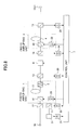
- FIG. 12 is a block diagram for explaining processing by the control unit 7 of the photo amplifying apparatus for making gain thereof flat.
- control unit 7 The processing by the control unit 7 is described below with reference to FIGs. 11 and 12.
- the photo signals are received and converted into current signals by the photo diodes 32-34, 35, and 36, and are converted into voltage signals by resistors R2-R4, R5, and R6.
- the voltage signals are amplified by amps 2-4, 5, 6, and further converted into digital signals by analog-digital converters ADC2-4, 5, and 6. Then, the digital signals are input to the control unit 7.
- the control unit 7 processes the input digital signals as follows (initial operation):
- control unit 7 If the control unit 7 receives an instruction to stop processing or detects that the input signal stops, the control unit 7 exits the processing (steps S18, S23).
- FIG. 13 is a schematic diagram showing a photo amplifying apparatus according to the third embodiment of the present invention.
- the photo amplifying apparatus shown in FIG. 13 is the same as the photo amplifying apparatus shown in FIG. 8 except that the fixed optical filter 51 that transmits photo signals of a specific wavelength is replaced with a variable optical filter 61 that transmits photo signals of a specific wavelength, and a drive circuit 71 that controls the variable optical filter 61. Any wavelength can be selected with these new components.
- the operation of the photo amplifying apparatus shown in FIG. 13 is basically identical to that of the photo amplifying apparatus shown in FIG. 8.
- the advantage of the photo amplifying apparatus according to the third embodiment is that, if the photo signal of the specific wavelength detected by the photo diode 31 stops due to a malfunction, for example, the control unit 7 causes the variable optical filter 61 to switch to another wavelength and continue monitoring the photo signal of the other wavelength.
- the control unit 7 of the photo amplifying apparatus shown in FIG. 8 fails to properly control the photo amplifying apparatus.
- FIG. 14 is a schematic diagram showing a photo amplifying apparatus according to the fourth embodiment of the present invention.
- the photo amplifying apparatus shown in FIG. 14 is different from the photo amplifying apparatus shown in FIG. 10 in that the fixed optical filter 52 that transmits a specific wavelength is replaced with a variable optical filter 62 that transmits a variable wavelength, and a drive circuit 72 for controlling the variable optical filter 62 is added. Accordingly, even if the photo signal of the specific wavelength detected by the photo diode 36 stops due to a malfunction, for example, the variable optical filter 62 can select an alternative wavelength and continue to monitor the photo signal of the alternative wavelength.
- the photo amplifying apparatus according to the fourth embodiment operates in the same manner as the photo amplifying apparatus according to the second embodiment except that, even if the photo signal of the specific wavelength stops, the control unit 7 causes the filter drive circuit 72 to switch the stopped wavelength to another wavelength and continues to properly control.
- FIG. 15 is a schematic diagram showing a photo amplifying apparatus according to the fifth embodiment of the present invention.
- the fifth embodiment is the combination of the first embodiment and the second embodiment.
- the photo amplifying apparatus shown in FIG. 15 is different in that it is provided with both fixed optical filters 51 and 52 and both photo diodes 31 and 36.
- the photo amplifying apparatus can determine the number of wavelengths as soon as the number of wavelengths changes. Using the determined number of wavelengths, the photo amplifying apparatus can make the gain thereof flat.
- FIG. 16 is a schematic diagram showing a photo amplifying apparatus according to the sixth embodiment.
- the sixth embodiment is the combination of the third embodiment and the fourth embodiment.
- the photo amplifying apparatus shown in FIG. 16 is different from the photo amplifying apparatus shown in FIG. 15 in that the fixed optical filters 51 and 52 are replaced with variable optical filters 61 and 62, and drive circuits 71 and 72 are added.
- the drive circuits 71 and 72 control the variable optical filters 61 and 62, respectively, so that the variable optical filters 61 and 62 transmit photo signals of which the wavelength is variably determined by the control unit 7. Accordingly, the control unit 7 of the photo amplifying apparatus shown in FIG. 16 can arbitrarily determine the wavelength of the photo signals that transmit the variable optical filters 61 and 62.
- the photo amplifying apparatus according to the sixth embodiment shown in FIG. 16 operates basically in the same manner as the photo amplifying apparatus according to the fifth embodiment shown in FIG. 15. If the photo signal of the wavelength that is monitored by the photo diodes 31 and 36 stops due to a malfunction, for example, the control unit 7 of the photo amplifying apparatus according to the fifth embodiment can no longer be properly controlled by the photo amplifying apparatus. However, the control unit 7 of the photo amplifying apparatus according to the sixth embodiment can continuously control the photo amplifying apparatus according to the sixth embodiment by switching the monitored wavelength to another wavelength. Accordingly, the control unit 7 can continue to properly control the photo amplifying apparatus.
- the photo amplifying apparatus controls output signal level by detecting, based on the change in photo signals, changes in the number of wavelengths and gain gradient of the photo signals.
Landscapes
- Physics & Mathematics (AREA)
- Electromagnetism (AREA)
- Engineering & Computer Science (AREA)
- Plasma & Fusion (AREA)
- Optics & Photonics (AREA)
- Computer Networks & Wireless Communication (AREA)
- Signal Processing (AREA)
- Optical Communication System (AREA)
- Lasers (AREA)
Abstract
Description
Accordingly, the output control unit can continuously control the photo amplifying apparatus.
Claims (8)
- A photo amplifying apparatus for amplifying wavelength division multiplexed signals, comprising:a specific wavelength measuring unit that measures the light power of photo signals of a specific wavelength at a measuring point;a total power measuring unit that measures the light power of said photo signals of all wavelengths at said measuring point; andan output control unit that controls the output of said photo amplifying apparatus based on the light power measured by said specific wavelength measuring unit and the light power measured by said total power measuring unit.
- The photo amplifying apparatus as claimed in claim 1, wherein said specific wavelength measuring unit further comprises a variable-wavelength optical filter.
- The photo amplifying apparatus as claimed in claim 1, wherein
said measuring point is positioned at one of an input stage, an intermediate stage, and an output stage; and
said output control unit, when the light power measured by said specific wavelength measuring unit does not change and the light power measured by said total power measuring unit changes, determines the number of multiplexed wavelengths of said photo signals based on the light power measured by said specific wavelength measuring unit and the light power measured by said total power measuring unit. - The photo amplifying apparatus as claimed in claim 1, wherein said output control unit, when change in the light power measured by said specific wavelength measuring unit is equal to change in the light power measured by said total power measuring unit, controls the output of said photo amplifying apparatus based on the light power measured by said specific wavelength measuring unit and the light power measured by said total power measuring unit so as to compensate for the loss of photo transmission path.
- The photo amplifying apparatus as claimed in claim 1, wherein
said measuring point is positioned at an output stage; and
said output control unit controls the output of said photo amplifying apparatus based on the number of multiplexed wavelengths, the light power measured by said specific wavelength measuring unit, and the light power measured by said total power measuring unit so as to compensate a gain gradient of output photo signals. - A method by a photo amplifying apparatus of determining change in the number of multiplexed wavelengths in received wavelength division multiplexed signals, wherein a measuring point is provided in one of an input stage, an intermediate stage, and an output stage, comprising the steps of:measuring the light power of a specific wavelength at said measuring point;measuring the light power of all wavelengths at said measuring point; anddetermining, when the measured light power of said specific wavelength does not change, and the measured light power of all wavelengths changes, change in the number of multiplexed wavelengths based on the measured light power of said specific wavelength and the measured light power of all wavelengths.
- A method by a photo amplifying apparatus of determining change in the signal level of wavelength division multiplexed signals, comprising the steps of:measuring the light power of a specific wavelength at a measuring point provided in said photo amplifying apparatus;measuring the light power of all wavelengths at said measuring point; anddetermining, when change in the measured light power of said specific wavelength is equal to change in the measured light power of all wavelengths, change in the signal level of wavelength division multiplexed signals transmitted through a photo transmission path based on said change in the measured light power of said specific wavelength or said change in the measured light power of all wavelengths.
- A method by a photo amplifying apparatus of processing wavelength division multiplexed signals in which a plurality of wavelengths are multiplexed, comprising the steps of:receiving said signals from an exterior source;measuring the light power of a specific wavelength at a measuring point provided in said photo amplifying apparatus;measuring the light power of all wavelengths at said measuring point;determining, when change in the measured light power of said specific wavelength is equal to change in the measured light power of all wavelengths, change in the signal level of wavelength division multiplexed signals transmitted through a photo transmission path based on said change in the measured light power of said specific wavelength or said change in the measured light power of all wavelengths; anddetermining, when the measured light power of said specific wavelength does not change, and the measured light power of all wavelengths changes, change in the number of multiplexed wavelengths based on the measured light power of said specific wavelength and the measured light power of all wavelengths.
Applications Claiming Priority (2)
| Application Number | Priority Date | Filing Date | Title |
|---|---|---|---|
| JP2002264261A JP4084144B2 (en) | 2002-09-10 | 2002-09-10 | Optical amplifier |
| JP2002264261 | 2002-09-10 |
Publications (3)
| Publication Number | Publication Date |
|---|---|
| EP1398894A2 true EP1398894A2 (en) | 2004-03-17 |
| EP1398894A3 EP1398894A3 (en) | 2005-07-20 |
| EP1398894B1 EP1398894B1 (en) | 2007-02-28 |
Family
ID=31884755
Family Applications (1)
| Application Number | Title | Priority Date | Filing Date |
|---|---|---|---|
| EP03255109A Expired - Lifetime EP1398894B1 (en) | 2002-09-10 | 2003-08-18 | Light amplifying apparatus for wavelength division multiplexing capable for determining change in number of multiplexed wavelength signals |
Country Status (4)
| Country | Link |
|---|---|
| US (1) | US7612936B2 (en) |
| EP (1) | EP1398894B1 (en) |
| JP (1) | JP4084144B2 (en) |
| DE (1) | DE60312085T2 (en) |
Families Citing this family (14)
| Publication number | Priority date | Publication date | Assignee | Title |
|---|---|---|---|---|
| JPH0589250U (en) * | 1991-09-05 | 1993-12-07 | 良雄 矢野 | Structure of a packaging bag outlet with a chuck seal and a sealing seal |
| US8909038B2 (en) * | 2003-01-07 | 2014-12-09 | Alcatel Lucent | Method and apparatus providing transient control in optical add-drop nodes |
| WO2005117215A1 (en) * | 2004-05-26 | 2005-12-08 | Mitsubishi Denki Kabushiki Kaisha | Optical amplifier and its gain controlling method |
| JP4769443B2 (en) * | 2004-09-16 | 2011-09-07 | 富士通株式会社 | Control device and control method for optical amplification device |
| JP4773703B2 (en) * | 2004-10-26 | 2011-09-14 | 住友電気工業株式会社 | Optical amplifier |
| JP4826514B2 (en) * | 2007-03-14 | 2011-11-30 | 株式会社日立製作所 | Optical transmission apparatus and control method thereof |
| JP5003878B2 (en) * | 2007-03-27 | 2012-08-15 | 日本電気株式会社 | Submarine cable gain equalization method and gain equalization apparatus |
| JP5428278B2 (en) * | 2008-10-14 | 2014-02-26 | 富士通株式会社 | Optical amplifier control device |
| WO2011161929A1 (en) * | 2010-06-24 | 2011-12-29 | 三菱電機株式会社 | Wavelength multiplex transmission device |
| JP2012043934A (en) * | 2010-08-18 | 2012-03-01 | Fujitsu Ltd | Amplification device, communication system and amplification method |
| US10491296B1 (en) * | 2018-09-12 | 2019-11-26 | Verizon Patent And Licensing Inc. | Systems and methods for passive optical network integrated tool |
| CN112986663B (en) | 2019-12-13 | 2025-03-14 | 福州高意通讯有限公司 | A detection structure and method for feedforward pump failure in L-band optical fiber amplifier |
| DE102020133142B4 (en) * | 2019-12-13 | 2025-03-20 | Ii-Vi Delaware, Inc. | BLIND PUMP LASER DETECTION |
| JP7729374B2 (en) * | 2021-03-03 | 2025-08-26 | 日本電気株式会社 | Light control device, repeater, and control method for light control device |
Family Cites Families (10)
| Publication number | Priority date | Publication date | Assignee | Title |
|---|---|---|---|---|
| JP3379052B2 (en) | 1994-09-26 | 2003-02-17 | 富士通株式会社 | WDM optical amplifier, WDM transmission system, and WDM transmission method |
| JPH08264871A (en) | 1995-03-20 | 1996-10-11 | Fujitsu Ltd | Multi-wavelength batch optical amplifier |
| JPH095212A (en) | 1995-06-19 | 1997-01-10 | Sumitomo Electric Ind Ltd | Optical fiber amplifier evaluation method and apparatus |
| JP3363003B2 (en) * | 1995-10-03 | 2003-01-07 | 株式会社日立製作所 | Optical amplifier and optical transmission system using optical amplifier |
| JP3422398B2 (en) * | 1995-12-07 | 2003-06-30 | 富士通株式会社 | Center-of-gravity wavelength monitoring method and apparatus, optical amplifier, and optical communication system |
| JP3306713B2 (en) | 1996-05-02 | 2002-07-24 | 富士通株式会社 | Optical amplifier |
| IT1296852B1 (it) * | 1996-12-10 | 1999-08-02 | Nec Corp | Amplificatore ottico e procedimento e apparecchiatura di controllo di guadagno di amplificatore ottico |
| JP3851007B2 (en) | 1998-12-18 | 2006-11-29 | 富士通株式会社 | Wavelength multiplexed light detector |
| JP2000312046A (en) | 1999-04-27 | 2000-11-07 | Hitachi Ltd | Optical transmission device, optical amplification device, and optical transmission system |
| KR20010003638A (en) | 1999-06-24 | 2001-01-15 | 윤종용 | Apparatus and method for stabilizing output power of wavelength division multiplexed erbium doped fiber amplifier in respect of channel number |
-
2002
- 2002-09-10 JP JP2002264261A patent/JP4084144B2/en not_active Expired - Fee Related
-
2003
- 2003-08-13 US US10/639,467 patent/US7612936B2/en not_active Expired - Fee Related
- 2003-08-18 DE DE60312085T patent/DE60312085T2/en not_active Expired - Lifetime
- 2003-08-18 EP EP03255109A patent/EP1398894B1/en not_active Expired - Lifetime
Also Published As
| Publication number | Publication date |
|---|---|
| JP4084144B2 (en) | 2008-04-30 |
| JP2004103861A (en) | 2004-04-02 |
| EP1398894B1 (en) | 2007-02-28 |
| US7612936B2 (en) | 2009-11-03 |
| EP1398894A3 (en) | 2005-07-20 |
| DE60312085T2 (en) | 2007-06-06 |
| US20040057732A1 (en) | 2004-03-25 |
| DE60312085D1 (en) | 2007-04-12 |
Similar Documents
| Publication | Publication Date | Title |
|---|---|---|
| US5864423A (en) | Optical amplifier, method of controlling the output light from the optical amplifier, optical transmission system and method of controlling an optical transmission path | |
| US6690506B2 (en) | Control architecture and method for optical amplifiers | |
| US6288836B1 (en) | Optical amplifier and optical communication system having the optical amplifier | |
| JP3306700B2 (en) | Optical amplifier and wavelength division multiplexing optical transmission system | |
| US6560008B1 (en) | Controlling apparatus and controlling method for wavelength division multiplexing optical amplifier | |
| EP1398894B1 (en) | Light amplifying apparatus for wavelength division multiplexing capable for determining change in number of multiplexed wavelength signals | |
| CN112075039A (en) | Automatic optical link calibration with channel keeper | |
| JP2723067B2 (en) | Optical amplifier | |
| US20030053196A1 (en) | Dynamic controller for a multi-channel optical amplifier | |
| US6599039B1 (en) | Optical transmission monitoring apparatus, optical transmission monitoring method, optical amplification system, method of controlling optical amplification system, and optical transmission system | |
| US20020122242A1 (en) | Optical repeater using raman amplification, wavelength division multiplexed light transmission system, excitation light supply method and excitation light control method for raman amplification | |
| US6373625B1 (en) | Method, apparatus, and system for optical amplification | |
| KR100210913B1 (en) | Optical amplifier having auto signal trcking filter and there fore operating method | |
| EP1763167A1 (en) | Optical amplification apparatus having function of flattening channel output spectrum | |
| US7554720B2 (en) | Optical transmission apparatus with automatic gain control and automatic level control mode selection | |
| US7206512B2 (en) | Method of controlling optical wavelength division multiplexing transmission apparatus | |
| JP2000349717A (en) | Device and method for amplifying light | |
| JP3362761B2 (en) | Optical amplifier for wavelength multiplex transmission | |
| US20030090785A1 (en) | Light amplifier and light transmission system using the same | |
| JP3490292B2 (en) | Optical transmission device and its wavelength maintenance device | |
| JP3353294B2 (en) | Optical transmission monitoring device, optical transmission monitoring method, optical amplification system, optical amplification system control method, and optical transmission system | |
| JP2000059312A (en) | Optical wavelength multiplex transmitter | |
| JP2001036475A (en) | Output stabilizing apparatus and method corresponding to the number of channels of wavelength division multiplexing optical fiber amplifier | |
| KR20020043684A (en) | Detecting apparatus and method for input channel number in optical amplifier | |
| JP2000261384A (en) | Variable light gain equalizer and optical amplifier for multi-wavelength transmission using same |
Legal Events
| Date | Code | Title | Description |
|---|---|---|---|
| PUAI | Public reference made under article 153(3) epc to a published international application that has entered the european phase |
Free format text: ORIGINAL CODE: 0009012 |
|
| AK | Designated contracting states |
Kind code of ref document: A2 Designated state(s): AT BE BG CH CY CZ DE DK EE ES FI FR GB GR HU IE IT LI LU MC NL PT RO SE SI SK TR |
|
| AX | Request for extension of the european patent |
Extension state: AL LT LV MK |
|
| PUAL | Search report despatched |
Free format text: ORIGINAL CODE: 0009013 |
|
| AK | Designated contracting states |
Kind code of ref document: A3 Designated state(s): AT BE BG CH CY CZ DE DK EE ES FI FR GB GR HU IE IT LI LU MC NL PT RO SE SI SK TR |
|
| AX | Request for extension of the european patent |
Extension state: AL LT LV MK |
|
| 17P | Request for examination filed |
Effective date: 20060116 |
|
| AKX | Designation fees paid |
Designated state(s): DE FR GB |
|
| GRAP | Despatch of communication of intention to grant a patent |
Free format text: ORIGINAL CODE: EPIDOSNIGR1 |
|
| GRAS | Grant fee paid |
Free format text: ORIGINAL CODE: EPIDOSNIGR3 |
|
| GRAA | (expected) grant |
Free format text: ORIGINAL CODE: 0009210 |
|
| AK | Designated contracting states |
Kind code of ref document: B1 Designated state(s): DE FR GB |
|
| REG | Reference to a national code |
Ref country code: GB Ref legal event code: FG4D |
|
| REF | Corresponds to: |
Ref document number: 60312085 Country of ref document: DE Date of ref document: 20070412 Kind code of ref document: P |
|
| ET | Fr: translation filed | ||
| PLBE | No opposition filed within time limit |
Free format text: ORIGINAL CODE: 0009261 |
|
| STAA | Information on the status of an ep patent application or granted ep patent |
Free format text: STATUS: NO OPPOSITION FILED WITHIN TIME LIMIT |
|
| 26N | No opposition filed |
Effective date: 20071129 |
|
| REG | Reference to a national code |
Ref country code: FR Ref legal event code: PLFP Year of fee payment: 14 |
|
| REG | Reference to a national code |
Ref country code: FR Ref legal event code: PLFP Year of fee payment: 15 |
|
| REG | Reference to a national code |
Ref country code: FR Ref legal event code: PLFP Year of fee payment: 16 |
|
| PGFP | Annual fee paid to national office [announced via postgrant information from national office to epo] |
Ref country code: DE Payment date: 20180807 Year of fee payment: 16 Ref country code: FR Payment date: 20180712 Year of fee payment: 16 |
|
| PGFP | Annual fee paid to national office [announced via postgrant information from national office to epo] |
Ref country code: GB Payment date: 20180815 Year of fee payment: 16 |
|
| REG | Reference to a national code |
Ref country code: DE Ref legal event code: R119 Ref document number: 60312085 Country of ref document: DE |
|
| GBPC | Gb: european patent ceased through non-payment of renewal fee |
Effective date: 20190818 |
|
| PG25 | Lapsed in a contracting state [announced via postgrant information from national office to epo] |
Ref country code: DE Free format text: LAPSE BECAUSE OF NON-PAYMENT OF DUE FEES Effective date: 20200303 Ref country code: FR Free format text: LAPSE BECAUSE OF NON-PAYMENT OF DUE FEES Effective date: 20190831 |
|
| PG25 | Lapsed in a contracting state [announced via postgrant information from national office to epo] |
Ref country code: GB Free format text: LAPSE BECAUSE OF NON-PAYMENT OF DUE FEES Effective date: 20190818 |