EP1398868A2 - Apparatus and method for driving a brushless motor - Google Patents
Apparatus and method for driving a brushless motor Download PDFInfo
- Publication number
- EP1398868A2 EP1398868A2 EP03020791A EP03020791A EP1398868A2 EP 1398868 A2 EP1398868 A2 EP 1398868A2 EP 03020791 A EP03020791 A EP 03020791A EP 03020791 A EP03020791 A EP 03020791A EP 1398868 A2 EP1398868 A2 EP 1398868A2
- Authority
- EP
- European Patent Office
- Prior art keywords
- rotor
- drive
- angular position
- coils
- brushless motor
- Prior art date
- Legal status (The legal status is an assumption and is not a legal conclusion. Google has not performed a legal analysis and makes no representation as to the accuracy of the status listed.)
- Granted
Links
Images



Classifications
-
- H—ELECTRICITY
- H02—GENERATION; CONVERSION OR DISTRIBUTION OF ELECTRIC POWER
- H02P—CONTROL OR REGULATION OF ELECTRIC MOTORS, ELECTRIC GENERATORS OR DYNAMO-ELECTRIC CONVERTERS; CONTROLLING TRANSFORMERS, REACTORS OR CHOKE COILS
- H02P6/00—Arrangements for controlling synchronous motors or other dynamo-electric motors using electronic commutation dependent on the rotor position; Electronic commutators therefor
- H02P6/14—Electronic commutators
- H02P6/16—Circuit arrangements for detecting position
Definitions
- the present invention relates to an apparatus and method for driving a brushless motor.
- a typical brushless motor includes a rotor having opposite magnetic poles (N pole and S pole) on its periphery and a stator having a "Y" connection of three coils.
- the three coils are spaced from each other by 120 degrees, and face the rotor.
- the N pole of the rotor covers a half surface of the rotor, and the S pole covers the other half of the rotor. If viewed in a cross section of the rotor, the N pole extends 180 degrees of the periphery of the rotor and the S pole extends the other 180 degrees.
- the current angular position of the rotor is detected by a magnetic detector (e.g., Hall element), and drive currents are supplied to two of the three coils based on the current angular position of the rotor. Every time the rotor reaches a target angular position, the drive currents are supplied to appropriately selected two coils.
- a magnetic detector e.g., Hall element
- the conventional brushless motor is only able to control the angular position of the rotor at 60-degree intervals. Therefore, if the brushless motor is used in a mechanism to control the angular position of an electronic throttle valve of a vehicle's engine, it is not possible to precisely control the angular position of the electronic throttle valve.
- Relatively fine (delicate) control of the angular position may be achieved by reducing a rotation ratio of the rotor of the brushless motor by means of a gear train.
- the gear train can provide a gear ratio of 0.5 so that the angular position control can be carried out at 30-degree intervals.
- this way of improving the control has a limitation. Accordingly, high precision control cannot be achieved.
- An object of the present invention is to provide an apparatus and method for driving a brushless motor, which can provide high precision control of an angular position of a rotor at high precision.
- an improved apparatus for driving a brushless motor includes a rotor having opposite magnetic poles on its periphery, and a stator facing the rotor and having at least three interconnected coils at equal angular intervals.
- the number of the coils is a multiple of three (i.e., three, six, nine, ).
- the drive apparatus of the brushless motor includes a memory for storing drive data which represent drive currents supplied to the respective coils at each of predetermined angular positions of the rotor.
- the drive apparatus also includes a controller for reading those drive data which best match a target angular position of the rotor, from the memory. The controller produces drive signals based on the read drive data.
- the drive apparatus also includes a drive circuit for supplying the drive currents to the respective coils, based on the drive signals supplied from the controller, respectively.
- the drive apparatus can control the angular position of the brushless motor at high precision. Consequently, it is possible to control an angular position of, for example, an electronic throttle valve which is activated by the brushless motor.
- an improved method for driving a brushless motor includes a rotor having opposite magnetic poles on its periphery, and a stator facing the rotor and having at least three interconnected coils at equal angular intervals.
- the number of the coils is a multiple of three (i.e., three, six, nine, ).
- the drive method includes storing, in a memory, drive data which represent drive currents supplied to the respective coils at each of predetermined angular positions of the rotor.
- the drive method also includes reading those drive data which best match a target angular position of the rotor, from the memory, and producing drive signals based on the drive data.
- the drive method also includes transmitting the read drive currents to the respective coils, based on the produced drive signals, respectively.
- a drive apparatus 40 for a brushless motor 1 is illustrated.
- the drive apparatus 40 controls a degree of opening of an electronic throttle valve (not shown) of an internal combustion engine of a vehicle, using the brushless motor 1, based on a degree (or stroke) of depression of an accelerator pedal (not shown).
- the drive apparatus 40 includes a control circuit 2 and a plurality of FETs (field-effect transistors) 3 to 8 to rotate the brushless motor
- the FETs form in combination a drive circuit.
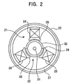
- the brushless motor 1 includes a stator 21 and a rotor 22, both housed in a cylindrical casing 23 .
- the stator 21 includes an iron core 27 having three inwardly projecting elements 28 to 30. Three coils 24 to 26 are wound around the three projecting elements 28 to 30, respectively. The coils 24 to 26 are "Y" connected, as shown in Figure 1.
- the iron core 27 has an annular shape.
- the three projecting elements 28 to 30 are spaced from each other at 120-degree intervals.
- the rotor 22 has a shaft 31 rotatably supported by bearings (not shown) provided in the casing 23.
- a magnet 32 is secured to a periphery of the rotating shaft 31.
- the magnet 32 has an S pole and an N pole. The S pole half of the magnet 32 extends 180 degrees in the rotating direction of the shaft 31, and the N pole half extends the other 180 degrees when viewed in cross section.
- the magnet 32 is exposed to the projecting members 28 to 30 of the stator 21.
- the control circuit 2 includes a microcomputer, and has six output terminals (or ports) UH, VH, WH, UL, VL and WL.
- the output terminals UH, VH, WH, UL, VL and WL are coupled to the FETs 3 to 8, respectively, such that one output terminal is connected to one gate of an associated FET.
- the output terminal UH is connected to one gate of the FET 3
- the output terminal VH is connected to one gate of the FET 4
- the output terminal WH is connected to one gate of the FET 5
- the output terminal UL is connected to one gate of the FET 6
- the output terminal VL is connected to one gate of the FET 7
- the output terminal WL is connected to one gate of the FET 8.
- Drains of the FETs 3 to 5 are connected to a line 42, and a voltage +B is applied to this line 42.
- the source of the FET 3 is connected to the drain of the FET 6 to define a source-drain connection, and a line 44 extends to one end of the coil 24 from this source-drain connection.
- the source of the FET 4 is connected to the drain of the FET 7 to define another source-drain connection, and a line 46 extends to one end of the coil 25 from this source-drain connection.
- the source of the FET 5 is connected to the drain of the FET 8, and a line 48 extends to one end of the coil 26 from the source-drain connection of the FETs 5 and 8.
- the sources of the FETs 6 to 8 are grounded.
- Hall elements 9 to 11 are provided in the vicinity of the surface of the rotor 22 at 60-degree intervals. A voltage Vcc is applied to each of the Hall elements 9 to 11. The Hall elements 9 to 11 produce pulse signals in accordance with magnetism variations caused by rotations of the rotor 22. Output signals of the Hall elements 9 to 11 are supplied to the control circuit 2. Upon receiving the signals from the Hall elements 9 to 11, the control circuit 2 supplies drive signals to the FETs 3 to 8 from the output ports UH, VH, WH, UL, VL and WL. The drive signals designate which FET(s) among the FETs 3 to 8 should be turned on. Each FET takes a drain-source "on” condition (saturated condition) or drain-source “off” condition (shutoff condition), based on the drive signal applied thereto.
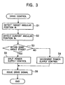
- the control circuit 2 repeatedly performs the drive control every several msec. As illustrated in Figure 3, the control circuit 2 firstly reads a desired angle ⁇ t of the rotor 22 (Step S1) and reads a current rotation angle ⁇ c of the rotor 22 (Step S2).
- the desired angle ⁇ t is determined on the basis of the degree (or stroke) of depression of the accelerator pedal.
- the desired angle ⁇ t can take a value between 0 degree and 1800 degrees (360 x 5) since the brushless motor 1 rotates five times when the accelerator pedal is depressed to the maximum depressed position from a non-actuated position.
- the desired angle is a value between 0 degree and 1800 degrees at one-degree intervals.
- the angle from 0 degree to 1800 degrees is segmented into a plurality of 60-degree sections. Each 60-degree section is referred to as an "angle stage.”
- the current rotation angle ⁇ c is the current angular position of the brushless motor 1, and is determined by the control circuit 2 for every 60 degrees, based on the pulse signals issued from the Hall elements 9 to 11. As shown in Figure 4 , the pulse signals from the Hall elements 9 to 11 have a 180-degree width and 60-degree phase difference from each other.
- the first pulse signal is produced from the Hall element 9
- the second pulse signal is produced from the Hall element 10
- the third pulse signal is produced from the Hall element 11.
- the brushless motor 1 rotates in a reverse direction
- the first pulse signal is generated from the Hall element 11
- the second pulse signal is generated from the Hall element 10
- the third pulse signal is generated from the Hall element 9.
- the control circuit 2 utilizes the counter to determine the motor's angle position ⁇ p (between 0 and 360 degrees) in the n' th rotation, based on the output signals of the Hall elements 9 to 11.
- the rotating direction of the brushless motor 1 is determined from the order of generation of the pulse signals from the Hall elements 9 to 11. Increment or decrement of the count of the counter is determined by the rotating direction of the brushless motor 1.
- n is used to indicate the rotation stage of the brushless motor 1 in this embodiment.
- Step S3 the control circuit 2 determines whether the current rotation angle ⁇ c is in the same angle stage as the target angle ⁇ t (Step S3) . In other words, it is determined whether the current angular position ⁇ c and the target angular position ⁇ t are in the same 60-degree section. If the current angular position ⁇ c is not within the same angle stage as the target angular position ⁇ t, the control circuit 2 performs 120-degree power supply control (Step S4). On the other hand, if the current angular position ⁇ c and the target angular position ⁇ t are within the same angle stage, then the control circuit 2 performs shunt (split) power supply control or high precision control (Step S5). The drive signals resulting from the control of Step S4 or S5 are supplied to the FETs 3 to 8 from the output ports UH, VH, WH, UL, VL and WL of the control circuit 2 (Step S6).
- a drive signal is generated in accordance with the difference ( ⁇ c - ⁇ t) between the current angular position ⁇ c and the target angular position ⁇ t.
- the drive signal is generated such that (until) the current angular position ⁇ c enters the same angle stage as the target angular position ⁇ t. For example, when the current angular position ⁇ c is different from the target angular position ⁇ t by 375 degrees, the drive signal is generated to rotate the brushless motor 1 360 degrees towards the target angular position ⁇ t.
- the output pulse signal is generated from the Hall element 9, and turns on the FET 3 as shown in Figure 4.
- the FET 7 is already turned on. Therefore, the drive signal of the brushless motor 1 flows in the FET 3, coil 24, coil 25 and FET 7.
- the rotor 22 of the brushless motor 1 rotates.
- the output pulse signal is generated from the Hall element 10.
- the FET 7 is turned off; and instead, the FET 8 is turned on.
- the drive current of the brushless motor 1 then flows in the FET 3, coil 24, coil 26 and FET 8.
- the rotor 22 of the brushless motor 1 rotates.
- the output pulse signal is generated from the Hall element 11.
- the FET 3 is turned off; and instead, the FET 4 is turned on.
- the drive current of the brushless motor 1 then flows in the FET 4, coil 25, coil 26 and FET 8, thereby rotating the rotor 22.
- the output pulse signal is no longer generated from the Hall element 9.
- the FET 8 is turned off; and instead, the FET 6 is turned on.
- the drive current of the brushless motor 1 then flows in the FET 4, coil 25, coil 2 4 and FET 6, thereby rotating the rotor 22.
- the output pulse is no longer generated from the Hall element 10.
- the FET 4 is turned off; and instead, the FET 5 is turned on.
- the drive current of the brushless motor 1 flows in the FET 5, coil 26, coil 24 and FET 6 to rotate the rotor 22.
- the output pulse is no longer generated from the Hall element 11.
- the FET 6 is turned off; and instead, the FET 7 is turned on.
- the drive current of the brushless motor 1 flows in the FET 5, coil 26, coil 25 and FET 7 to rotate the rotor 22. In this manner, the rotor 22 rotates 360 degrees.
- the brushless motor 1 can continuously rotate in the normal direction.
- the output pulses from the Hall elements 9 to 11 turn on and off the FETs 3 to 8 in the manner opposite to the above described normal rotation control.
- the above described 120-degree power supply control is carried out until the current angular position ⁇ c enters the angle stage of the target angular position ⁇ t.
- the rotation speed of the rotor 22 is reduced by reducing the amount of the currents supplied to the FETs.
- Step S3 determines that the angle stage of the current angular position ⁇ c matches the angle stage of the target angular position ⁇ t (i.e., the difference between the current angular position ⁇ c and the target angular position ⁇ t is less than 60 degrees)
- the control program proceeds to Step S5 to perform the shunt (split) power supply control.
- a data map is stored in a memory 2a of the control circuit 2.
- the data map includes 360 sets of drive data corresponding to the 360 sets of drive signals for 360 angular positions of the brushless motor 1.
- One set of drive data corresponds to one set of drive signals for a particular degree of 360 degrees.
- Each drive data represents a value of the current. It should be noted that the brushless motor 1 can rotate five times and take 1800 angular positions, but the same 360 sets of drive signals can be repeatedly used for each rotation.
- the control circuit 2 reads the drive data for the target angular position ⁇ t from the data map of the memory 2a, and supplies the drive data, as the drive signals, to the FETs 3 to 8.
- Figure 5 illustrates the current values, which are represented by the drive data stored in the data map, changing with the angular position of the brushless motor 1 between 0 degree and 360 degrees.
- the FETs 4 , 6 and 8 are in the off condition.
- the FETs 3, 5 and 7 are in the activated condition, based on the drive signals. It should be noted, however, that if the target angular position ⁇ t is zero degree, the FET 3 is turned off.
- A is the maximum value of the current. If the target angular position ⁇ t is zero degree, the drive current of the brushless motor 1 flows in the FET 5, coil 26, coil 25 and FET 7, thereby causing the rotor 22 to rotate to the target angular position ⁇ t. The rotor 22 stops at the target angular position. If the target angular position ⁇ t is between 1 and 59 degrees, one drive current flows in the FET 3 and coil 24, and another drive current flows in the FET 5 and coil 26. These two drive currents merge with each other at a mutual point of the Y connection, and flow into the coil 25 and FET 7, thereby causing the rotor 22 to rotate to the target angular position ⁇ t. The rotor 22 stops at the target angular position.
- the FETs 4, 5 and 6 are in the completely off condition.
- the FETs 3, 7 and 8 are activated by the drive signals. It should be noted, however, that if the target angular position ⁇ t is 60 degrees, the FET 8 is turned off.
- the drive current of the brushless motor 1 flows in the FET 3, coil 24, coil 25 and FET 7, thereby causing the rotor 22 to rotate to the target angular position ⁇ t.
- the rotor 22 stops at the target angular position. If the target angular position ⁇ t is between 61 and 119 degrees, the drive current flows in the FET 3 and coil 24, and branches at the branching point of the Y connection so that one drive current flows into the coil 25 and FET 7 and the other drive current flows into the oil 26 and FET 8, thereby causing the rotor 22 to rotate to the target angular position ⁇ t.
- the rotor 22 stops at the target angular position.
- the FETs 5, 6 and 7 are in the completely off condition.
- the FETs 3, 4 and 8 are activated by the drive signals. It should be noted, however, that if the target angular position ⁇ t is 120 degrees, the FET 4 is turned off.
- the drive current of the brushless motor 1 flows in the FET 3, coil 24, coil 26 and FET 8, thereby causing the rotor 22 to rotate to the target angular position ⁇ t.
- the rotor 22 stops at the target angular position. If the target angular position ⁇ t is between 121 and 179 degrees, one drive current flows in the FET 3 and coil 24 and the other drive current flows in the FET 4 and coil 25 . These two drive currents join with each other at the meeting point of the Y connection and flows in the coil 26 and FET 8, thereby causing the rotor 22 to rotate to the target angular position ⁇ t.
- the rotor 22 stops at the target angular position.
- the FETs 3, 5 and 7 are in the completely off condition.
- the FETs 4, 6 and 8 are activated by the drive signals. It should be noted, however, that if the target angular position ⁇ t is 180 degrees, the FET 6 is turned off.
- the rotor 22 stops at the target angular position. If the target angular position ⁇ t is between 181 and 239 degrees, the drive current flows in the FET 4 and coil 25 and branches at the branching point of the Y connection. One drive current then flows into the coil 24 and FET 6, and the other drive current flows into the coil 26 and FET 8, thereby causing the rotor 22 to rotate to the target angular position ⁇ t.
- the rotor 22 stops at the target angular position.
- the FETs 3 , 7 and 8 are in the completely off condition.
- the FETs 4, 5 and 6 are brought into the activated condition, based on the drive signals. It should be noted, however, that if the target angular position ⁇ t is 240 degrees, the FET 5 is turned off.
- the rotor 22 stops at the target angular position. If the target angular position ⁇ t is between 241 and 299 degrees, one drive current flows in the FET 4 and coil 25 and the other drive current flows in the FET 5 and coil 26. These drive currents join with each other at the mutual point of the Y connection, and flow in the coil 24 and FET 6, thereby causing the rotor 22 to rotate to the target angular position ⁇ t.
- the rotor 22 stops at the target angular position.
- the FETs 3, 4 and 8 are in the completely of f condition.
- the FETs 5, 6 and 7 are brought into the activated condition by the drive signals. It should be noted, however, that if the target angular position ⁇ t is 300 degrees, the FET 7 is turned off.
- the rotor 22 stops at the target angular position. If the target angular position ⁇ t is between 301 and 359 degrees, the drive current flows in the FET 5 and coil 26 and branches at the branching point of the Y connection. One drive current flows in the coil 24 and FET 6, and the other drive current flows in the coil 25 and FET 7, thereby causing the rotor 22 to rotate to the target angular position ⁇ t.
- the rotor 22 stops at the target angular position.
- the split power supply control therefore, can control the rotation angle of the rotor 22 with the intervals considerably smaller than the 120-degree power supply control. Specifically, the split power supply control controls the angular position (rotation angle) of the rotor 22 at one-degree intervals whereas the 120-degree power supply control controls the angular position of the rotor 22 at 60-degree intervals. As a result, it is possible to control the angular position of the electronic throttle valve, which moves in connection with the rotor 22, precisely with respect to the target angular position ⁇ t.
- the FET connected to that coil may be either in the off condition or the activated condition.
- the 120-degree power supply control is performed in the above described embodiment. It should be noted, however, that alternatively the split power supply control may be performed to rotate the rotor 22 at, for example, 30-degree intervals.
- the drive apparatus for the brushless motor is used for controlling the electronic throttle valve in the above described embodiments. It should be noted, however, that the drive apparatus can be applied to a brushless motor of a power sliding door or a power window.
- a drive system for a brushless motor includes a rotor having opposite magnetic poles on its periphery, and a stator facing the rotor.
- the stator has, for example, three interconnected coils at equal angular intervals.
- the drive system includes a memory for storing drive data which represent drive currents supplied to the respective coils at each angular position of the rotor.
- the drive system also includes a controller for reading those drive data which best match a target angular position of the rotor, from the memory. The controller generates drive signals based on the drive data.
- the drive system also includes a drive circuit for supplying the drive currents to the respective coils, based on the drive signals, respectively.
- the drive system can precisely control the angular position of the brushless motor.
Landscapes
- Engineering & Computer Science (AREA)
- Power Engineering (AREA)
- Control Of Motors That Do Not Use Commutators (AREA)
- Brushless Motors (AREA)
- Stopping Of Electric Motors (AREA)
Abstract
Description
Claims (20)
- A drive apparatus for a brushless motor, the brushless motor including a rotor having opposite magnetic poles arranged on a periphery of the rotor, and a stator facing the rotor and having at least three interconnected coils at equal angular intervals, the drive apparatus comprising:memory means for storing drive data which represent drive currents to be supplied to the respective coils at each of predetermined angular positions of the rotor;control means for reading those drive data which best match a target angular position of the rotor, from the memory means, and for generating drive signals based on the read drive data; anda drive circuit for supplying the drive currents to the respective coils, based on the generated drive signals.
- The drive apparatus according to claim 1, wherein the stator includes three coils, the drive apparatus further comprises a detector for detecting a current angular position of the rotor, and when a difference between the current angular position of the rotor and the target angular position is greater than a predetermined value, the control means does not read the drive data from the memory means, and instead selects two of the three coils based on the angular position difference and supplies signals to the drive circuit so as to supply appropriate currents to the selected two coils, until the angular position difference is not greater than the predetermined value.
- The drive apparatus according to claim 2, wherein the predetermined value is 60 degrees.
- The drive apparatus according to claim 1, 2 or 3, wherein the brushless motor controls movement of an electronic throttle valve of an engine.
- The drive apparatus according to claim 1, 2, 3 or 4, wherein the target angular position of the rotor is determined by a position of an accelerator pedal.
- The drive apparatus according to any one of foregoing claims, wherein the drive circuit includes a plurality of field-effect transistors.
- The drive apparatus according to any one of claims 2 to 6, wherein the detector includes at least one Hall element.
- The drive apparatus according to any one of claims 1 to 7, wherein the at least three interconnected coils are 3 x n coils (n is a natural number).
- A method for driving a brushless motor, the brushless motor including a rotor having opposite magnetic poles arranged on a periphery of the rotor, and a stator facing the rotor and having at least three interconnected coils at equal angular intervals, the method comprising:storing, in a memory, drive data which represent drive currents to be supplied to the respective coils at each of predetermined angular positions of the rotor;reading those drive data which best match a target angular position of the rotor, from the memory;generating drive signals based on the read drive data; andsupplying the drive currents to the respective coils based on the generated drive signals, respectively.
- The method according to claim 9, wherein the stator includes three coils, the method further comprises detecting a current angular position of the rotor, and when a difference between the current angular position of the rotor and the target angular position is greater than a predetermined value, the method further comprises selecting two of the three coils based on the angular position difference and supplying appropriate currents to the selected two coils, until the angular position difference is not greater than the predetermined value, prior to reading the drive data from the memory.
- The method according to claim 10, wherein the predetermined value is 60 degrees.
- The method according to claim 9, 10 or 11, wherein the brushless motor controls movement of an electronic throttle valve of an engine.
- The method according to claim 9 , 10 , 11 or 12 , wherein the target angular position of the rotor is determined by a position of an accelerator pedal.
- The method according to any one of claims 9 to 13, wherein the at least three interconnected coils are 3 x n coils (n is a natural number).
- An apparatus for driving a brushless motor, the brushless motor including a rotor having opposite magnetic poles arranged on a periphery of the rotor, and a stator facing the rotor and having three interconnected coils at equal angular intervals, the apparatus comprising:a controller for generating drive signals corresponding to a target angular position of the rotor, when a difference between the target angular position of the rotor and a current angular position of the rotor is smaller than a predetermined value; anda drive circuit for supplying drive currents to the respective coils, based on the generated drive signals.
- The apparatus according to claim 15, wherein if a difference between the current angular position of the rotor and the target angular position is greater than the predetermined value, the controller does not generate the drive signals, but selects two of the three coils based on the angular position difference and supplies signals to the drive circuit so as to supply appropriate currents to the selected two coils, until the angular position difference is not greater than the predetermined value.
- The apparatus according to claim 16, wherein the predetermined value is 60 degrees.
- The apparatus according to claim 15, 16 or 17, wherein the brushless motor controls movement of an electronic throttle valve of an engine.
- The apparatus according to any one of claims 15 to 18, wherein the target angular position of the rotor is determined by a position of an accelerator pedal.
- The apparatus according to any one of claims 15 to 19, wherein the drive circuit includes a plurality of field-effect transistors.
Applications Claiming Priority (2)
| Application Number | Priority Date | Filing Date | Title |
|---|---|---|---|
| JP2002266390 | 2002-09-12 | ||
| JP2002266390A JP4084982B2 (en) | 2002-09-12 | 2002-09-12 | Brushless motor driving apparatus and driving method |
Publications (3)
| Publication Number | Publication Date |
|---|---|
| EP1398868A2 true EP1398868A2 (en) | 2004-03-17 |
| EP1398868A3 EP1398868A3 (en) | 2005-04-13 |
| EP1398868B1 EP1398868B1 (en) | 2007-01-03 |
Family
ID=31884791
Family Applications (1)
| Application Number | Title | Priority Date | Filing Date |
|---|---|---|---|
| EP03020791A Expired - Lifetime EP1398868B1 (en) | 2002-09-12 | 2003-09-12 | Apparatus and method for driving a brushless motor |
Country Status (4)
| Country | Link |
|---|---|
| US (1) | US7081726B2 (en) |
| EP (1) | EP1398868B1 (en) |
| JP (1) | JP4084982B2 (en) |
| DE (1) | DE60310829T2 (en) |
Cited By (1)
| Publication number | Priority date | Publication date | Assignee | Title |
|---|---|---|---|---|
| WO2010128365A1 (en) * | 2009-05-07 | 2010-11-11 | Aktiebolaget Skf | Method and device for controlling a brushless motor |
Families Citing this family (10)
| Publication number | Priority date | Publication date | Assignee | Title |
|---|---|---|---|---|
| BR0100052B1 (en) * | 2001-01-11 | 2014-06-10 | Brasil Compressores Sa | REFRIGERATION SYSTEM, REFRIGERATOR AND CONTROL METHOD FOR A COMPRESSOR |
| US7293467B2 (en) | 2001-07-09 | 2007-11-13 | Nartron Corporation | Anti-entrapment system |
| DE10204199A1 (en) * | 2002-02-01 | 2003-08-07 | Pierburg Gmbh | Control device for a motor for adjusting an actuator |
| US7312591B2 (en) * | 2005-03-11 | 2007-12-25 | Npc Corporation | Powered panel moving system |
| JP2007068256A (en) * | 2005-08-29 | 2007-03-15 | Canon Inc | Stage device control method |
| US7342373B2 (en) * | 2006-01-04 | 2008-03-11 | Nartron Corporation | Vehicle panel control system |
| US8115427B2 (en) * | 2008-10-23 | 2012-02-14 | Won-Door Corporation | Methods, systems, and devices for a motor control system |
| US20110113772A1 (en) * | 2009-11-18 | 2011-05-19 | PlasmERG, Inc. | Plasmic transition process motor |
| JP5271327B2 (en) * | 2010-09-27 | 2013-08-21 | パナソニックEsパワーツール株式会社 | Electric tool |
| SE539525C2 (en) * | 2016-01-05 | 2017-10-10 | Scania Cv Ab | Spring return throttle actuator, method of control thereof and throttle assembly |
Family Cites Families (10)
| Publication number | Priority date | Publication date | Assignee | Title |
|---|---|---|---|---|
| JPH0749779B2 (en) * | 1988-06-14 | 1995-05-31 | 三菱電機株式会社 | Throttle actuator controller |
| US5193506A (en) * | 1989-04-17 | 1993-03-16 | Lucas Industries Public Limited Company | Engine throttle control system |
| EP0694203B1 (en) * | 1991-05-09 | 1998-04-15 | Nu-Tech And Engineering, Inc. | Electric motor, methods for controlling and assembling same |
| JPH08242596A (en) | 1995-03-03 | 1996-09-17 | Toshiba Corp | DC brushless motor and its control circuit |
| JP3399156B2 (en) * | 1995-05-29 | 2003-04-21 | 株式会社デンソー | Control device for brushless DC motor |
| JP3543896B2 (en) * | 1996-06-20 | 2004-07-21 | 三菱電機株式会社 | Engine intake air control system |
| JP3600418B2 (en) * | 1997-11-14 | 2004-12-15 | 三菱電機株式会社 | Actuator control device |
| JP3628855B2 (en) * | 1997-11-18 | 2005-03-16 | 三菱電機株式会社 | Control method and control device for engine intake air amount |
| JP2000270591A (en) * | 1999-03-18 | 2000-09-29 | Aisin Seiki Co Ltd | Electric motor chopping energization control device |
| JP3929665B2 (en) * | 1999-12-28 | 2007-06-13 | 三菱電機株式会社 | Engine intake air amount control device |
-
2002
- 2002-09-12 JP JP2002266390A patent/JP4084982B2/en not_active Expired - Fee Related
-
2003
- 2003-09-11 US US10/659,396 patent/US7081726B2/en not_active Expired - Fee Related
- 2003-09-12 EP EP03020791A patent/EP1398868B1/en not_active Expired - Lifetime
- 2003-09-12 DE DE60310829T patent/DE60310829T2/en not_active Expired - Lifetime
Cited By (1)
| Publication number | Priority date | Publication date | Assignee | Title |
|---|---|---|---|---|
| WO2010128365A1 (en) * | 2009-05-07 | 2010-11-11 | Aktiebolaget Skf | Method and device for controlling a brushless motor |
Also Published As
| Publication number | Publication date |
|---|---|
| JP2004104958A (en) | 2004-04-02 |
| EP1398868B1 (en) | 2007-01-03 |
| US20040051490A1 (en) | 2004-03-18 |
| EP1398868A3 (en) | 2005-04-13 |
| DE60310829T2 (en) | 2007-05-16 |
| JP4084982B2 (en) | 2008-04-30 |
| US7081726B2 (en) | 2006-07-25 |
| DE60310829D1 (en) | 2007-02-15 |
Similar Documents
| Publication | Publication Date | Title |
|---|---|---|
| US5350984A (en) | Method and apparatus for starting a brushless DC motor | |
| EP1588481B1 (en) | Phase advance angle optimization for brushless motor control | |
| US7072778B2 (en) | Method and system for determining a rotor position in a wound field DC motor | |
| US7081726B2 (en) | Apparatus and method for driving a brushless motor | |
| US7304450B2 (en) | Motor-reduction unit switched on an absolute position signal | |
| US20020171388A1 (en) | Apparatus for driving three-phase half-wave drive brushless motor | |
| CA2387158A1 (en) | For driving step motors without overshoot | |
| JP2004012299A (en) | Rotation angle detector for synchronous rotating machine | |
| US20100225259A1 (en) | Brushless Motor Apparatus | |
| EP0989664B1 (en) | Driving device for three-phase brushless motor | |
| US6469463B2 (en) | Brushless motor and driving control device therefor | |
| US7077087B2 (en) | Valve timing controller | |
| US20020167290A1 (en) | Apparatus for driving three-phase brushless motor | |
| EP1143600B1 (en) | Stepping motor and driving apparatus | |
| US20080061724A1 (en) | Position detection device for permanent magnetic machines | |
| US7279863B2 (en) | Method and apparatus for detecting excitation position of SRM by comparison of detected current | |
| US5206571A (en) | Stepper motor controllers | |
| US5717592A (en) | Method and system for engine throttle control | |
| CN101141105A (en) | Non-sensing starting method of brushless DC motor | |
| JP2006151335A (en) | Power steering device | |
| US6798164B2 (en) | Initializing drive apparatus | |
| DE102017206333A1 (en) | MOTORSTEUERVORRICHTUG | |
| US11515823B2 (en) | Control of a single coil BLDC motor | |
| US8026683B2 (en) | Motor controller | |
| US20220173675A1 (en) | Method for the vibration-reduced operation of a bldc motor |
Legal Events
| Date | Code | Title | Description |
|---|---|---|---|
| PUAI | Public reference made under article 153(3) epc to a published international application that has entered the european phase |
Free format text: ORIGINAL CODE: 0009012 |
|
| AK | Designated contracting states |
Kind code of ref document: A2 Designated state(s): AT BE BG CH CY CZ DE DK EE ES FI FR GB GR HU IE IT LI LU MC NL PT RO SE SI SK TR |
|
| AX | Request for extension of the european patent |
Extension state: AL LT LV MK |
|
| PUAL | Search report despatched |
Free format text: ORIGINAL CODE: 0009013 |
|
| AK | Designated contracting states |
Kind code of ref document: A3 Designated state(s): AT BE BG CH CY CZ DE DK EE ES FI FR GB GR HU IE IT LI LU MC NL PT RO SE SI SK TR |
|
| AX | Request for extension of the european patent |
Extension state: AL LT LV MK |
|
| RIC1 | Information provided on ipc code assigned before grant |
Ipc: 7H 02P 6/16 A |
|
| 17P | Request for examination filed |
Effective date: 20050627 |
|
| AKX | Designation fees paid |
Designated state(s): DE FR |
|
| GRAP | Despatch of communication of intention to grant a patent |
Free format text: ORIGINAL CODE: EPIDOSNIGR1 |
|
| GRAS | Grant fee paid |
Free format text: ORIGINAL CODE: EPIDOSNIGR3 |
|
| GRAA | (expected) grant |
Free format text: ORIGINAL CODE: 0009210 |
|
| AK | Designated contracting states |
Kind code of ref document: B1 Designated state(s): DE FR |
|
| REF | Corresponds to: |
Ref document number: 60310829 Country of ref document: DE Date of ref document: 20070215 Kind code of ref document: P |
|
| ET | Fr: translation filed | ||
| PLBE | No opposition filed within time limit |
Free format text: ORIGINAL CODE: 0009261 |
|
| STAA | Information on the status of an ep patent application or granted ep patent |
Free format text: STATUS: NO OPPOSITION FILED WITHIN TIME LIMIT |
|
| 26N | No opposition filed |
Effective date: 20071005 |
|
| PGFP | Annual fee paid to national office [announced via postgrant information from national office to epo] |
Ref country code: FR Payment date: 20100921 Year of fee payment: 8 |
|
| PGFP | Annual fee paid to national office [announced via postgrant information from national office to epo] |
Ref country code: DE Payment date: 20100908 Year of fee payment: 8 |
|
| REG | Reference to a national code |
Ref country code: FR Ref legal event code: ST Effective date: 20120531 |
|
| REG | Reference to a national code |
Ref country code: DE Ref legal event code: R119 Ref document number: 60310829 Country of ref document: DE Effective date: 20120403 |
|
| PG25 | Lapsed in a contracting state [announced via postgrant information from national office to epo] |
Ref country code: DE Free format text: LAPSE BECAUSE OF NON-PAYMENT OF DUE FEES Effective date: 20120403 |
|
| PG25 | Lapsed in a contracting state [announced via postgrant information from national office to epo] |
Ref country code: FR Free format text: LAPSE BECAUSE OF NON-PAYMENT OF DUE FEES Effective date: 20110930 |